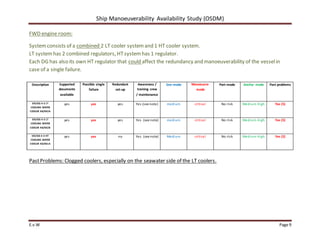
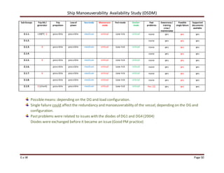
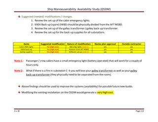
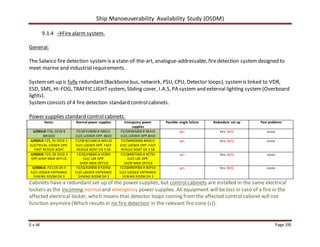
This document provides an equipment breakdown and analysis of critical systems on HAL's Vista class vessels. It identifies single points of failure that could impact propulsion and maneuverability. The goals are to evaluate redundancy, identify high-risk areas, and modify systems to improve reliability. Several cooling water systems are identified as critical, as a single failure could disable multiple diesel generators. Modifications are recommended, such as adding a second high temperature cooler. Proper crew training and maintenance are also emphasized to minimize risks from the vessels' integrated systems.

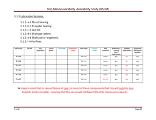


![Propulsion%20system %203rd[1]](https://cdn.slidesharecdn.com/ss_thumbnails/propulsion20system-203rd1-140408015635-phpapp01-thumbnail.jpg?width=640&height=640&fit=bounds)


