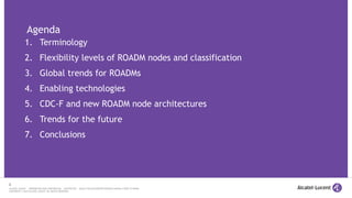
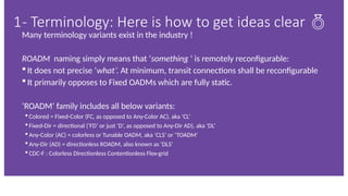
Many terminology variantsexist in the industry !
ROADM naming simply means that ‘something ’ is remotely reconfigurable:
It does not precise ‘what’. At minimum, transit connections shall be reconfigurable
It primarily opposes to Fixed OADMs which are fully static.
‘ROADM’ family includes all below variants:
Colored = Fixed-Color (FC, as opposed to Any-Color AC), aka ‘CL’
Fixed-Dir = directional (‘FD’ or just ‘D’, as opposed to Any-Dir AD), aka ‘DL’
Any-Color (AC) = colorless or Tunable OADM, aka ‘CLS’ or ‘TOADM’
Any-Dir (AD) = directionless ROADM, also known as ‘DLS’
CDC-F : Colorless Directionless Contentionless Flex-grid
1- Terminology: Here is how to get ideas clear
4.
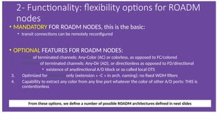
• MANDATORY FORROADM NODES, this is the basic:
• transit connections can be remotely reconfigured
• OPTIONAL FEATURES FOR ROADM NODES:
1. Color of terminated channels: Any-Color (AC) or colorless, as opposed to FC/colored
2. Direction of terminated channels: Any-Dir (AD), or directionless as opposed to FD/directional
• existence of anydirectional A/D block or so called local OTS
3. Optimized for coherent only (extension « -C » in arch. naming): no fixed WDM filters
4. Capability to extract any color from any line port whatever the color of other A/D ports: THIS is
contentionless
From these options, we define a number of possible ROADM architectures defined in next slides
2- Functionality: flexibility options for ROADM
nodes
5.
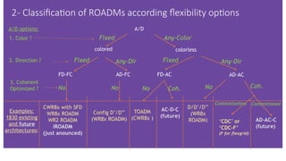
A/D
Fixed Any-Color
colored colorless
1.Color ?
2. Direction ? Fixed Any-Dir Fixed Any-Dir
FD-FC AD-FC FD-AC AD-AC
A/D options:
3. Coherent
Optimized ? No No No No
Coh. Coh.
CWR8x with SFD
WR8x ROADM
WR2 ROADM
iROADM
(just anounced)
Config D’/D’’
(WR8x ROADM)
TOADM
(CWR8x )
AC-D-C
(future)
D/D’/D’’
(WR8x
ROADM) ‘CDC’ or
‘CDC-F’
(F for flexgrid)
Examples:
1830 existing
and future
architectures:
Contentionless Contentioned
AD-AC-C
(future)
2- Classification of ROADMs according flexibility options
6.
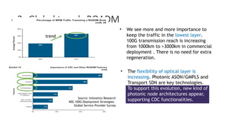
3- Global trendsROADM
Source: Infonetics Research
40G 100G Deployment Strategies:
Global Service Provider Survey
• We see more and more importance to
keep the traffic in the lowest layer.
100G transmission reach is increasing
from 1000km to >3000km in commercial
deployment . There is no need for extra
regeneration.
• The flexibility of optical layer is
increasing. Photonic ASON/GMPLS and
Transport SDN are key technologies.
To support this evolution, new kind of
photonic node architectures appear,
supporting CDC functionalities.
trend
7.
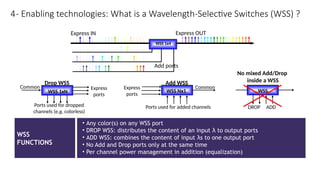
WSS
FUNCTIONS
• Any color(s)on any WSS port
• DROP WSS: distributes the content of an input λ to output ports
• ADD WSS: combines the content of input λs to one output port
• No Add and Drop ports only at the same time
• Per channel power management in addition (equalization)
Ports used for dropped
channels (e.g. colorless)
Common Express
ports
WSS 1xN
Drop WSS
WSS Nx1
Ports used for added channels
Common
Express
ports
Add WSS
DROP ADD
WSS
No mixed Add/Drop
inside a WSS
Express IN
Add ports
WSS 1x4
Express OUT
4- Enabling technologies: What is a Wavelength-Selective Switches (WSS) ?
8.
mixer
mixer
ADC
DSP
Local oscillator (laser)
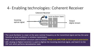
•The Local Oscillator is a laser at the same nominal frequency as the transmitted signal and has the same
function as local oscillators in wireless transmissions
• Mixer is an interferometric structure used to extract PHASE and AMPLITUDE of EACH optical polarization
• ADC (Analog to Digital Converter) is used to digitize the incoming electrical signal, and hand it to the
DSP unit which performs demodulation tasks
Incoming
optical signal
Coherent Receiver
Output
digital stream
4- Enabling technologies: Coherent Receiver
9.
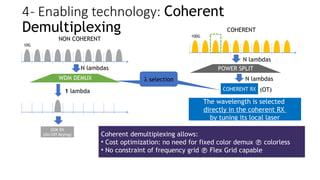
WDM DEMUX
OOK RX
(On/OffKeying)
COHERENT RX
10G
100G
The wavelength is selected
directly in the coherent RX
by tuning its local laser
Coherent demultiplexing allows:
• Cost optimization: no need for fixed color demux colorless
• No constraint of frequency grid Flex Grid capable
NON COHERENT
COHERENT
POWER SPLIT
N lambdas
1 lambda
N lambdas
N lambdas
l selection
l selection
4- Enabling technology: Coherent
Demultiplexing
(OT)
10.
WSS
…
l1 ln
WSS
Coupler
WSS-based
Tunable Demux
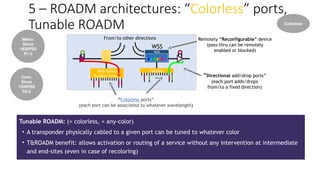
TunableROADM: (= colorless, = any-color)
• A transponder physically cabled to a given port can be tuned to whatever color
• T&ROADM benefit: allows activation or routing of a service without any intervention at intermediate
and end-sites (even in case of recoloring)
Remotely “Reconfigurable” device
(pass-thru can be remotely
enabled or blocked)
“Directional add/drop ports”
(each port adds/drops
from/to a fixed direction)
“Colorless ports”
(each port can be associated to whatever wavelength)
From/to other directions
Metro:
Since
1830PSS
R1.0
Core:
Since
1830PSS
R3.6
Colorless
5 – ROADM architectures: “Colorless” ports,
Tunable ROADM
11.
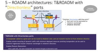
WSS
…
l1 ln
WSS
WSS-based
Tunable Demux
From/toother directions
WSS-based
Tunable Mux
• T&ROADM with Directionless ports
A transponder cabled to a given port can be tuned to whatever color, and can transmit/receive to/from whatever direction
Enables remote rerouting of dynamic traffic with minimum deployed resources (existing transponders can be used to
transmit/regenerate/recolor whatever wavelength in whatever direction)
Enables Photonic Restoration:
when a path fails, the same transponder can transmit through an alternative route
“Colorless Directionless add/drop ports”
• Each port can be associated to:
• whatever wavelength
• whatever direction
Since
1830PSS
R3.6
Colorless
Directionless
5 – ROADM architectures: T&ROADM with
“Directionless” ports
12.
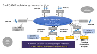
5 – ROADMarchitctures: low contention
WR8-88
WR8-88
WR8-88 WR8-88
WR8-88
WR8-88
…
x8
CWR8-88 CWR8-88
• Multiple A/D blocks can strongly mitigate contention
• If # A/D blocks = # DEGREES NO CONTENTION
WR8-88
WR8-88
…
x8
CWR8-88 CWR8-88
Since
1830PSS
R3.6
Colorless
Directionless
MESH CONNECTIONS:
all to all
(drawing simplified)
…
…
…
…
West Line
North Line East Line
South Line
Directionless
A/D blocks
Directionless
A/D blocks
Colorless
directionless
A/D ports
N
N N
N
N
N
Nx1 WSS
inside on Tx 1xN WSS
inside on Rx
1xN WSS
inside on Rx
13.
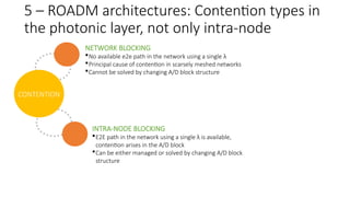
NETWORK BLOCKING
No availablee2e path in the network using a single λ
Principal cause of contention in scarsely meshed networks
Cannot be solved by changing A/D block structure
CONTENTION
INTRA-NODE BLOCKING
E2E path in the network using a single λ is available,
contention arises in the A/D block
Can be either managed or solved by changing A/D block
structure
5 – ROADM architectures: Contention types in
the photonic layer, not only intra-node
14.
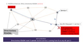
A
B
C
D
A/D contention:
Directionless ROADMnode D cannot receive service 2 coming from B on any-dir port 2
Directionless
ROADMs
Any-Dir Drop port 1: service 1
lk
lk
A/D contention:
Any-Dir Drop port 2
CANNOT terminate
service 2 coming from B
Service 2
Service 1
5 – ROADM architectures: What a directionless ROADM cannot do
15.
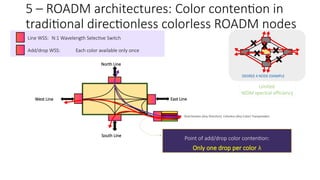
Directionless (Any Direction)Colorless (Any Color) Transponders
Line WSS: N:1 Wavelength Selective Switch
Add/drop WSS: Each color available only once
North Line
South Line
West Line East Line
DEGREE 4 NODE EXAMPLE
Limited
WDM spectral efficiency
Point of add/drop color contention:
Only one drop per color
5 – ROADM architectures: Color contention in
traditional directionless colorless ROADM nodes
16.
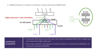
CONTENTION
IN ADD/DROP
• Inthe same WSS device, the same color can only be multiplexed ONCE from a single input
port toward the single output port
• Intra-node contention only happens in Anydir A/D block (i.e. Directionless ROADMs), not
an issue for directional ROADMs
To Line WSS
N E S W
λ1 to S λ1 to W
N:1 WSS device
λ1 to N λ1 to E
N ports
1 port
WR8-88
WR8-88
Color
Contentions
in A/D
Single output port = Color Contentions
5 – ROADM architectures: Contention in A/D blocks in colorless directionless ROADM nodes
17.
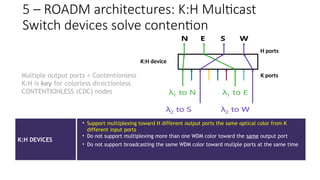
K:H DEVICES
• Supportmultiplexing toward H different output ports the same optical color from K
different input ports
• Do not support multiplexing more than one WDM color toward the same output port
• Do not support broadcasting the same WDM color toward muliple ports at the same time
λ1 to N λ1 to E
N E S W
λ2 to S λ2 to W
K:H device
K ports
H ports
Multiple output ports = Contentionless
K:H is key for colorless directionless
CONTENTIONLESS (CDC) nodes
5 – ROADM architectures: K:H Multicast
Switch devices solve contention
18.
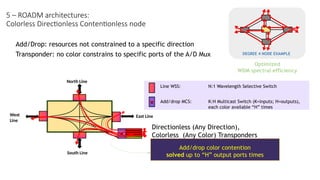
Line WSS: N:1Wavelength Selective Switch
Add/drop MCS: K:H Multicast Switch (K=inputs; H=outputs),
each color available “H” times
Add/Drop: resources not constrained to a specific direction
Transponder: no color constrains to specific ports of the A/D Mux
Directionless (Any Direction),
Colorless (Any Color) Transponders
North Line
South Line
West
Line
East Line
DEGREE 4 NODE EXAMPLE
Optimized
WDM spectral efficiency
Add/drop color contention
solved up to “H” output ports times
5 – ROADM architectures:
Colorless Directionless Contentionless node
19.
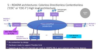
No contentionby design
Hardware ready to support Flexible Grid
Supports up to 192 A/D channels per node in 1830PSS R8.0, pure coherent only, 8 line degrees
FIBER SHUFFLE
(MSH8-FSM)
WR20-TFM
WR20-TFM
WR20-TFM
WR20-TFM
MCS8-16
…
AMP ARRAY (AAR8A)
MCS8-16
AMP ARRAY (AAR8A)
Switched-gain
amplifiers
K:H devices
inside
A/D allows
Multiple times lk
Multiple l
incl. lk
Multiple l
incl. lk
5 – ROADM architectures: Colorless Directionless Contentionless
(‘CDC’ or ‘CDC-F’) High level architecture
1830PSS
R8.0
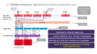
20x1 WSS inside
on Tx/Rx
20.
20:1 WSS
8 ports:Line
12 ports: a/d
16:8 (K:H) MCS
4 Bidir Amp
WSS WSS WSS WSS WSS
Fiber Shuffle
Amps
8x16 8x16 8x16
16 Line
interfaces
16 Line
interfaces
(130SCUPC,
130SNX10,
260SCX2)
1 to 16 1 to 16
1 to 8 1 to 8 1 to 8
Amps Amps Amps Amps Amps
1 to 12 blocks
1 to 12
1 to 24
1 to 8
Amps Amps
1 to 12 1 to 12 1 to 12 1 to 12
Colorless add/drop: Up to 192 step 1 (expandable)
Optimized for Coherent signals only
Ready for Flexible Grid applications (including
A/D of Superchannels)
Resolving up to H=8 color contention per wavelength
A/D block group
Line 1 Line 2 Line 3 Line 4 Line 8
WR20-TFM
MSH8-FSM
AAR8A
MCS8-16
New building
blocks in
1830PSS
Multiple lk
Multiple l
incl. lk
Multiple l
incl. lk
5 – ROADM architectures: CDC detailed functional building blocks view
21.
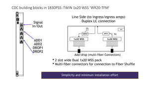
2 slotwide Dual 1x20 WSS pack
Multi-fiber connectors for connection to Fiber Shuffle
1x20 WSS
WTD
2%
Line Side (to ingress/egress amps)
Duplex LC connection
Add/drop (multi-fiber Connectors)
1x20 WSS
WTD 5%
INV
•Signal
In/Out
ADD1
ADD2
DROP1
DROP2
Simplicity and minimum installation effort
CDC building blocks in 1830PSS: TWIN 1x20 WSS ‘WR20-TFM’
22.
To
Fiber
Shuffle
To
MCS
card
Drop OA
Add OA
310 10 3
RS-232 Comms
Alarms & Controls
Analog controls
Power Supplies
Disable
WSS facing MPO
(8 of 12 fibers used)
MCS facing MPO
OA1
OA2
OA3
OA4
OA5
OA6
OA7
OA8
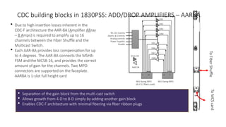
Due to high insertion losses inherent in the
CDC-F architecture the AAR-8A (Amplifier ARray
– 8 Amps) is required to amplify up to 16
channels between the Fiber Shuffle and the
Multicast Switch.
Each AAR-8A provides loss compensation for up
to 4-degrees. The AAR-8A connects the MSH8-
FSM and the MCS8-16, and provides the correct
amount of gain for the channels. Two MPO
connectors are supported on the faceplate.
AAR8A is 1-slot full height card
Separation of the gain block from the multi-cast switch
Allows growth from 4-D to 8-D simply by adding another gain block
Enables CDC-F architecture with minimal fibering via fiber ribbon plugs
CDC building blocks in 1830PSS: ADD/DROP AMPLIFIERS – AAR8A
23.
To
Amps
(D1-4)
To
Amps
(D5-8)
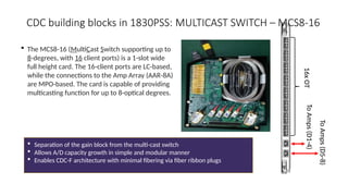
16x
OT
The MCS8-16(MultiCast Switch supporting up to
8-degrees, with 16 client ports) is a 1-slot wide
full height card. The 16-client ports are LC-based,
while the connections to the Amp Array (AAR-8A)
are MPO-based. The card is capable of providing
multicasting function for up to 8-optical degrees.
Separation of the gain block from the multi-cast switch
Allows A/D capacity growth in simple and modular manner
Enables CDC-F architecture with minimal fibering via fiber ribbon plugs
CDC building blocks in 1830PSS: MULTICAST SWITCH – MCS8-16
24.
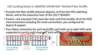
• Provides thefiber shuffle between degrees, to/from the MCS add/drop
blocks, and to the expansion layer of the CDC-F ROADM.
• Passive, rack mounted 3-RU pizza box style card that handles all of the WSS
interconnections including the mesh connections, pre-configured for
degree 8 support.
• Two ribbon connectors for each dual WSS card (with up to eight WSS cards
supported to service eight degrees); each with up to 20 fibers.
3RU
To/From WR20-TFM
To/From AAR-8A
for Degrees 1-4
To/From AAR-8A
for Degrees 5-8
Future
expansion
CDC building blocks in 1830PSS: MSH8-FSM- Meshed Fiber Shuffle
25.
T
X
P
MESH CONNECTIONS
WR8-88
WR8-88
WR8-88 WR8-88
T
X
P
WR8-88
CWR8-88
ITLB
SFD44BSFD44B
WR8-88
CWR8-88
ITLB
SFD44B
SFD44B
WR8-88
WR8-88
WR8-88 WR8-88
T
X
P
WR8-88
WR8-88
…
x8
CWR8-88 CWR8-88
WR8-88
WR8-88
…
x8
CWR8-88 CWR8-88
T
X
P
MESH CONNECTIONS
MESH CONNECTIONS
WR20-TF
WR20-TF
WR20-TF WR20-TF
AMPARRAY
…
x28
MULTICAST
SWITCH
MULTICAST
SWITCH
AMPARRAY
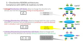
• Colored/Directionless A/D blocks allow to change the direction of a
service, but not the color, thus limiting re-routing options
• Colorless/Directionless A/D blocks allow to change both the color and the
direction of a service, but are still prone to contention in case the desired
color is already in use in the A/D block
• Colorless/Directionless/Contentionless A/D blocks allow to change both
the color and the direction of a service without constraints on the desired
color
TX
P
TX
P
TX
P
TX
P
Anydir but
fixed color
Any-Dir,
Any-Color
Any-Dir, Any-Color,
no A/D contention
5 – Directionless ROADM architectures:
Compliance with GMPLS & readiness to SDN Conf D’
Conf D
CDC
26.
Provisioning
Disaster Recovery
Management of
Spares
OpticalSpectrum
Defragmentation
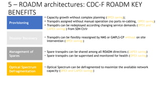
• Capacity growth without complex planning (OPEX saving);
• Transpdrs assigned without manual operation (no ports re-cabling, OPEX saving)
• Transpdrs can be redeployed according changing service demands (OPEX and
CAPEX savings) from SDN Ctrlr
• Transpdrs can be flexibly reassigned by NMS or GMPLS-CP without on site
intervention (OPEX savings)
• Spare transpdrs can be shared among all ROADM directions (CAPEX saving)
• Spare transpdrs can be supervised and monitored for health (OPEX saving)
• Optical Spectrum can be defragmented to maximize the available network
capacity (OPEX and CAPEX savings)
5 – ROADM architectures: CDC-F ROADM KEY
BENEFITS
27.
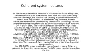
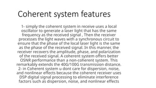
Coherent system features
Asmobile networks evolve towards LTE, smart terminals are widely used,
and new services such as FBB users' IPTV, VoD, and cloud computing
continue to emerge, the transmission capacity of conventional networks
cannot meet requirement. To address the requirements, Huawei
introduces transmission systems using the coherent technology. Huawei
coherent transmission systems use advanced technologies such as ePDM-
QPSK, ePDM-BPSK, and coherent detection to meet the high-speed
transmission requirements on OSNR, CD tolerance, PMD tolerance, and
nonlinear effects. Huawei provides large-capacity coherent solutions,
offering ultra-large bandwidths (100G and 40G).
A system using a coherent board (such as LSC, LTX, TN15LSXL, TN55NS3,
and TN54NS4) is a coherent transmission system.
100G/40G ePDM-BPSK systems are coherent systems. They use DSP chips
for coherent detection, delivering superior performance in mitigating
dispersion. Therefore, no DCM is required in these systems for dispersion
compensation.
For 40G DQPSK systems and other non-coherent systems, DCMs are
required for dispersion compensation. The DCU board can also be used on
the line.
28.
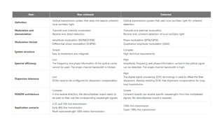
Coherent system features
1-simply the coherent system in receive uses a local
oscillator to generate a laser light that has the same
frequency as the received signal , Then the receiver
processes the light waves with a synchronous circuit to
ensure that the phase of the local laser light is the same
as the phase of the received signal. In this manner, the
receiver recovers the amplitude, phase, and polarization
of the received signal. A coherent system offers better
OSNR performance than a non-coherent system. This
remarkably extends the 40G/100G transmission distance.
2- in Coherent system u dont care for dispersion, noise,
and nonlinear effects because the coherent receiver uses
DSP digital signal processing to eliminate interference
factors such as dispersion, noise, and nonlinear effects
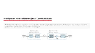
Principles of CoherentCommunication
Coherent communication technologies mainly include coherent modulation and coherent detection.
Coherent modulation uses the signals that are propagated to change the frequencies, phases, and
amplitudes of optical carriers. (Intensity modulation only changes the strength of light.)
Modulation detection mixes the laser light generated by a local oscillator (LO) with the incoming
signal light using an optical hybrid to produce an IF signal that maintains the constant frequency,
phase, and amplitude relationships with the signal light.
Formula for calculating optical signal electrical field strength:
)]
(
cos[
)
(
)
( t
t
t
A
t
E
where A is the amplitude, ω is the center frequency, and Φ is the phase. Therefore, the modulation
techniques can be: amplitude shift keying (ASK), frequency shift keying (FSK), and phase shift
keying (PSK). Fig 3
The quick oscillations represent the
frequency or phase changes in the
optical carrier.
The figure on the right shows the ASK,
FSK, and PSK modulation techniques.
Page 35
36.
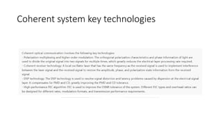
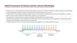
Principles of CoherentCommunication
An optical signal is modulated by its amplitude, frequency or phase with the modulated frequency
(assuming that the modulated frequency is ωs) over an optical carrier. When the optical signal is sent to
the optical receiver, it is mixed with the optical signal produced by the LO ωL. Then the photodetector
detects the mixed signal and produces an electrical signal that satisfies the ωIF = ωs-ωL formula.
According to the propagation theory for plane harmonic waves, the complex electric field distribution for
the received optical signal Es(t) and LO optical EL(t) can be calculated using the following formulas:
)]
(
exp[
)
( L
t
L
j
L
E
t
L
E
)]
(
exp[
)
( s
t
s
j
s
E
t
s
E
where,
Es: amplitude in the electric field of the received optical signal
EL: amplitude in the electric field of the LO optical signal
Φs: modulated phase of the received optical signal
ΦL: modulated phase of the LO optical signal
When Es(t) and EL(t) are parallel to each other and evenly fall onto the surface of the photodetector,
the intensity I of the overall incident light is proportional to [Es(t) + EL(t)]. That is, the following
formula is satisfied:
)
cos(
2
)
( L
S
IF
L
S
L
S t
P
P
R
P
P
R
I
In the formula, R is the response of the photodetector, PS and PL are the power of the
received optical signal and power of the LO optical signal, respectively.
(Formula 1)
(Formula 2)
(Formula 3)
Page 36
37.
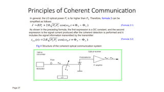
Principles of CoherentCommunication
In general, the LO optical power PL is far higher than PS. Therefore, formula 3 can be
simplified as follows:
)
cos(
2 L
S
IF
L
S
L t
P
P
R
RP
I
(Formula 3.1)
As shown in the preceding formula, the first expression is a DC constant, and the second
expression is the signal current produced after the coherent detection is performed and it
includes the signal information transmitted by the transmitter:
)
cos(
2
)
( L
S
IF
L
S
out t
P
P
R
t
i
(Formula 3.2)
Fig 4 Structure of the coherent optical communication system
Page 37
38.
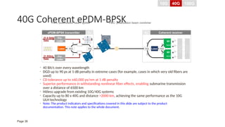
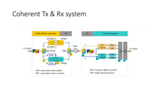
40G Coherent ePDM-BPSK
•40 Bit/s over every wavelength
• DGD up to 90 ps at 1 dB penalty in extreme cases (for example, cases in which very old fibers are
used)
• CD tolerance up to ±60,000 ps/nm at 1 dB penalty
• Superior performance in withstanding nonlinear fiber effects, enabling submarine transmission
over a distance of 6500 km
• Hitless upgrade from existing 10G/40G systems
• Capacity up to 80 x 40G and distance >2000 km, achieving the same performance as the 10G
ULH technology
• Note: The product indicators and specifications covered in this slide are subject to the product
documentation. This note applies to the whole document.
21.5 Gbit/s
Data
Laser
Pre-
coder
Pre-
coder
21.5Gb/s
Data
PBS
x
y
PBC
x
y
PBS Laser
90o
Hybrid
90o
Hybrid
PBS
x
y
ADC
DSP
Tx Rx Coherent receiver
ePDM-BPSK transmitter
0
1
PBS: polarization beam splitter PBC: polarization beam combiner
10G 40G 100G
Page 38
39.
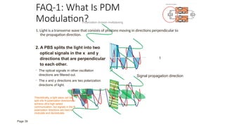
FAQ-1: What IsPDM
Modulation?
1. Light is a transverse wave that consists of photons moving in directions perpendicular to
the propagation direction.
t
Signal propagation direction
Photon
oscillation
direction
2. A PBS splits the light into two
optical signals in the x and y
directions that are perpendicular
to each other.
• The optical signals in other oscillation
directions are filtered out.
• The x and y directions are two polarization
directions of light.
Polarization division multiplexing
Theoretically, a light wave can be
split into N polarization directions to
achieve ultra-high-speed
communication, but signals in the N
polarization directions are hard to
modulate and demodulate.
Page 39
40.
Signal Input
I Q
Signal
Output
Phase
θ
00
0 1
1 1
1 0
π/4
3π/4
5π/4
7π/4
28Gb/s Data Pre-
coder
Pre-
coder
28Gb/s Data
Σ
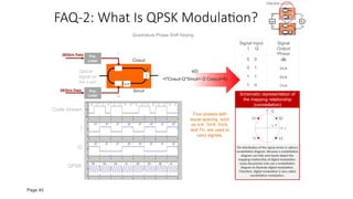
FAQ-2: What Is QPSK Modulation?
π/2
Optical
signal on
the x-pol
Sinωt
Cosωt
I
Q
+
-
s(t)
=I*Cosωt-Q*Sinωt=√2 Cos(ωt+θ)
I
Q
00
01
11 10
Schematic representation of
the mapping relationship
(constellation)
The distribution of the signal vector is called a
constellation diagram. Because a constellation
diagram can fully and clearly depict the
mapping relationship of digital modulation,
many documents only use a constellation
diagram to illustrate digital modulation.
Therefore, digital modulation is also called
constellation modulation.
Code stream
I
Q
QPSK
θ
Quadrature Phase Shift Keying
Four phases with
equal spacing, such
as π/4, 3π/4, 5π/4,
and 7π, are used to
carry signals.
Page 40
41.
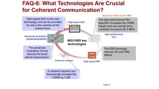
FAQ-6: What TechnologiesAre Crucial
for Coherent Communication?
40G/100G key
technologies
DSP
High speed DSP
Advanced modulation
(ePDM-QPSK/BPSK)
Coherent receiver
High performance
FEC
High speed ADC
The high performance FEC
algorithm increases the OSNR
margin and can provide error
correction to ensure 4E-3 BER.
The DSP technique
reduces CD and PMD
effects.
High-speed ADC is the core
technology and can be provided
by only a few vendors at the
present time.
The advanced
modulation format
reduces the baud
rate for transmission.
A coherent receiver can
theoretically increase the
OSNR by 3 dB.
Known as HFEC on the NMS
Page 41
42.
ePDM-QPSK Transmitter CoherentReceiver
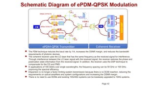
Schematic Diagram of ePDM-QPSK Modulation
The PDM technique reduces the baud rate by 1/4, increases the OSNR margin, and reduces the bandwidth
requirements of photonic devices.
The coherent receiver uses the LO laser that has the same frequency as the received signal for interference.
Through interference between the LO laser signal with the received signal, the receiver restores the phase and
polarization state information from the received signal. In addition, the receiver uses the DSP technique to
compensate for the CD and PMD.
In applications of 100 Gbit/s over single wavelengths, the frequency spacing can be 50 GHz or 100 GHz,
improving the spectral efficiency.
Dispersion is no longer a factor limiting system transmission because there is no DCM insertion, reducing the
requirements on optical amplifiers and system configurations and increasing the OSNR margin.
There is no need to use DCMs and existing 10G/40G systems can be losslessly upgraded to 100G systems.
Page 42
43.
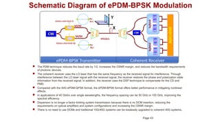
ePDM-BPSK Transmitter CoherentReceiver
Schematic Diagram of ePDM-BPSK Modulation
The PDM technique reduces the baud rate by 1/2, increases the OSNR margin, and reduces the bandwidth requirements
of photonic devices.
The coherent receiver uses the LO laser that has the same frequency as the received signal for interference. Through
interference between the LO laser signal with the received signal, the receiver restores the phase and polarization state
information from the received signal. In addition, the receiver uses the DSP technique to compensate for the CD and
PMD.
Compared with the 40G ePDM-QPSK format, the ePDM-BPSK format offers better performance in mitigating nonlinear
effects.
In applications of 40 Gbit/s over single wavelengths, the frequency spacing can be 50 GHz or 100 GHz, improving the
spectral efficiency.
Dispersion is no longer a factor limiting system transmission because there is no DCM insertion, reducing the
requirements on optical amplifiers and system configurations and increasing the OSNR margin.
There is no need to use DCMs and traditional 10G/40G systems can be losslessly upgraded to coherent 40G systems.
Page 43
44.
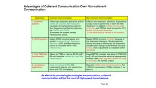
Advantages of CoherentCommunication Over Non-coherent
Communication
Application Coherent Communication Non-coherent Communication
1. DCM-free
systems
Offers high dispersion tolerance and no
DCMs are required, eliminating the
necessity of engineering surveys for
fiber dispersion and thereby reducing
the CAPEX and OPEX.
Eliminates the system penalty
introduced by DCMs.
Offers a low dispersion tolerance. Engineering
survey must be performed to learn the fiber
dispersion. In addition, DCMs must be used
on the line and TDCMs must be used for OTU
boards to fine-tune dispersion.
DCMs will introduce penalty to the systems.
2. ASON systems Makes ASON rerouting easier and
quicker because of high dispersion
tolerance. (DSP enables dispersion
search to complete within 1000
milliseconds.)
Makes ASON rerouting complex because of
low dispersion tolerance. Routes selection
during rerouting is affected by the dispersion
compensation design and therefore rerouting
is slow. (TDC adjustment is completed within
seconds.)
3. High PMD fiber
transmissions
Allows for PMD as high as 25-30 ps@1
dB and therefore suitable for most fiber
transmissions.
Uses DQPSK modules that allow for PMD of 6
ps@1dB and therefore electrical regenerators
must be used when high PMD fibers are used,
for example, the Telmex project.
4. Low-latency
applications
Does not require DCMs. The
transmission latency only results from
fibers and FEC processing.
Requires DCMs which introduce latency. For
1000 km transmission, DCMs introduce 1 ms
latency.
As electrical processing technologies become mature, coherent
communication will be the trend of high-speed transmissions.
Page 44
45.
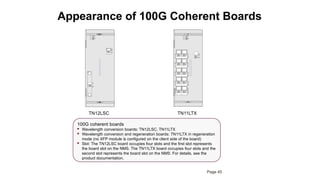
Appearance of 100GCoherent Boards
TN12LSC
100G coherent boards
Wavelength conversion boards: TN12LSC, TN11LTX
Wavelength conversion and regeneration boards: TN11LTX in regeneration
mode (no XFP module is configured on the client side of the board)
Slot: The TN12LSC board occupies four slots and the first slot represents
the board slot on the NMS. The TN11LTX board occupies four slots and the
second slot represents the board slot on the NMS. For details, see the
product documentation.
TN11LTX
STAT
ACT
PROG
SRV
OUT
IN
LSC
TX
RX
LSC
STAT
ACT
PROG
SRV
OUT
IN
LTX
LTX
TX2
RX2
TX4
RX4
TX6
RX6
TX8
RX8
TX10
RX10
RX1
TX1
RX3
TX3
RX5
TX5
RX7
TX7
RX9
TX9
Page 45
46.
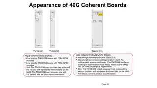
Appearance of 40GCoherent Boards
100G coherent line boards
Line boards: TN55NS3 boards with PDM-BPSK
modules
Line boards: TN56NS3 boards with PDM-QPSK
modules
Slot: The TN55NS3 board occupies two slots and
the second slot represents the board slot on the
NMS. The TN56NS3 board occupies one slot.
For details, see the product documentation.
TN55NS3 TN15LSXL
40G coherent tributary/line boards
Wavelength conversion boards: TN15LSXL
Wavelength conversion and regeneration board: No
independent regeneration board. The TN55NS3 line board
working in regeneration mode (Relay Mode on the NMS)
can be used for electrical regeneration.
Slot: The TN15LSXL board occupies three slots and the
second (middle) slot represents the board slot on the NMS.
For details, see the product documentation.
NS3
NS3
STAT
ACT
PROG
SRV
IN
OUT
NS3
NS3
STAT
ACT
PROG
SRV
IN
OUT
TN56NS3
Page 46
Editor's Notes
#12 In the following slides we will review 4 approaches that can be very effective in mitigating intra-node contention.
The first solution is to increase the number of anydir A/D blocks in the node when traffic grows. In the slide we show a 4 degree nodes with 3 anydir A/D blocks. 1830 supports up to 10 degrees where the degree is either a line degree or an anydir A/D block. For example a degree 7 can scale up to 3 anydir A/D blocks, a degree 6 up to 4 and so on. Note that in case line degree = A/D block number, the contention is solved.
This approach allows for a very modular solution and can substantially reduce contention
#13 First of all it’s important to distinguish between the two causes of contention in a network:
1- Network blocking: in this case a WDM demand cannot be routed in because an available e2e path is not available using a single lambda. This is the main cause of contention in lightly meshed networks (average degree ~3) and cannot be solved with any A/D block structure. The only way to deal with this contention cause is to either add additional fibers on a path or to increase the level of meshing in the network
2- Intra-node blocking: in this case a path is available in the network but the required color cannot be used in the existing A/D blocks. This problem can be solved using inherently contentionless A/D blocks that make sure the required color is always available, or can be mitigated using various means
In the following slides we will clarify where contention arises in the node and the possible approaches that can be used to mitigate the contention.
#40 1. Gray code:
The QPSK coordinates are four symmetric points on a circle. Using four phases, the QPSK modulation scheme encodes 2-bit symbols. The QPSK coordinates are represented using gray codes as 00, 01, 11, 10 rather than using conventional binary bits (00, 01, 10, and 11). According to the preceding information, gray code is a binary numeral system where two successive values differ in only one bit.
The use of gray codes is to minimize the BER. Let us use the phase corresponding to binary digits "11" as an example for illustration. When detecting errors, a conventional modulation system generally checks the 01 and 10 values only. Because there is only one bit error, most of the error processing schemes can restore the correct signal (for example, the conventional FEC can correct one bit error).
If conventional bit codes 00, 01, 10, and 11 are used, the data receiver will regard the codes 11 as the adjacent codes 10 or 00. When the receiver regards the codes 11 as 00, the two bits are incorrect and the receive can hardly recover the source signal using an error correction technique. Therefore bit errors are generated.
2. I/Q modulation in the figure
I/Q modulation is also called quadrature modulation because the I and Q signals are modulated onto carriers that are perpendicular to each other. One of the carriers used by the I/Q modulation is a cosine wave and the other is a sine wave. The cosine wave is perpendicular to the sine wave, which means they differ by π/2 phase (90 degrees).
In the figure, the optical signal on the x-pol is split into two. Assuming that the signal is cosωt (independent of the initial phase), the lower signal is sinωt after the phase is shifted by π/2. The two signals are transmitted in directions perpendicular to each other.
3.
Optical communication is a method of transmitting information by mainly using two properties of light: propagation speed and anti-interference capability. Take the laser signal operating at 192.1 THz as an example (the signal can be generated by a laser of which the center wavelength of the laser light is 192.1 THz). The signal transmits 192.1*1012 wavelengths every second. A 40G signal is 43 Gbit/s and that of a 100G signal is 100 Gbit/s, which means 43 or 100 x 109 bits are transmitted every second. Therefore, each signal bit occupies up to one thousand wavelengths of an optical signal. Generally, the waveform of a high-frequency signal is called "envelope".


![Principles of Coherent Communication
Coherent communication technologies mainly include coherent modulation and coherent detection.
Coherent modulation uses the signals that are propagated to change the frequencies, phases, and
amplitudes of optical carriers. (Intensity modulation only changes the strength of light.)
Modulation detection mixes the laser light generated by a local oscillator (LO) with the incoming
signal light using an optical hybrid to produce an IF signal that maintains the constant frequency,
phase, and amplitude relationships with the signal light.
Formula for calculating optical signal electrical field strength:
)]
(
cos[
)
(
)
( t
t
t
A
t
E
where A is the amplitude, ω is the center frequency, and Φ is the phase. Therefore, the modulation
techniques can be: amplitude shift keying (ASK), frequency shift keying (FSK), and phase shift
keying (PSK). Fig 3
The quick oscillations represent the
frequency or phase changes in the
optical carrier.
The figure on the right shows the ASK,
FSK, and PSK modulation techniques.
Page 35](https://image.slidesharecdn.com/opticaltxlec12ppt-250928203804-15ed2e33/85/optical-tx-lec-12-PPT-Presentations-design-pptx-35-320.jpg)
![Principles of Coherent Communication
An optical signal is modulated by its amplitude, frequency or phase with the modulated frequency
(assuming that the modulated frequency is ωs) over an optical carrier. When the optical signal is sent to
the optical receiver, it is mixed with the optical signal produced by the LO ωL. Then the photodetector
detects the mixed signal and produces an electrical signal that satisfies the ωIF = ωs-ωL formula.
According to the propagation theory for plane harmonic waves, the complex electric field distribution for
the received optical signal Es(t) and LO optical EL(t) can be calculated using the following formulas:
)]
(
exp[
)
( L
t
L
j
L
E
t
L
E
)]
(
exp[
)
( s
t
s
j
s
E
t
s
E
where,
Es: amplitude in the electric field of the received optical signal
EL: amplitude in the electric field of the LO optical signal
Φs: modulated phase of the received optical signal
ΦL: modulated phase of the LO optical signal
When Es(t) and EL(t) are parallel to each other and evenly fall onto the surface of the photodetector,
the intensity I of the overall incident light is proportional to [Es(t) + EL(t)]. That is, the following
formula is satisfied:
)
cos(
2
)
( L
S
IF
L
S
L
S t
P
P
R
P
P
R
I
In the formula, R is the response of the photodetector, PS and PL are the power of the
received optical signal and power of the LO optical signal, respectively.
(Formula 1)
(Formula 2)
(Formula 3)
Page 36](https://image.slidesharecdn.com/opticaltxlec12ppt-250928203804-15ed2e33/85/optical-tx-lec-12-PPT-Presentations-design-pptx-36-320.jpg)