SlideShare a Scribd company logo
What is One Wire Serial Communication
● Serial data transmission over one wire(duh)
● Great for cheap applications that don't require high speed data transfer
● In theory, all AVR processors can handle One Wire Communication
● Timing is extremely important
○ The only way to discern signals from other signals
How Does it Work?
● Two basic implementations
○ Polled Implementations(software only)
○ Interrupt driven (counter required)
● Dallas 1-Wire Protocol
○ Designed by the Dallas Semiconductor Corporation
○ Can use either interrupt driven or polled implementations
○ Polled requires no external hardware
○ Half Duplex(transmitting or receiving not Both simultaneously)
Dallas 1-Wire
● Signal is idle High, need pull up resistor
● Signaling is divided into time slots of 60µs
● Master initiates every communication
○ Regardless of direction
● 5 basic signals: (Write 1, Write 0, Read, Reset, Presence)
● LSB sent first
Overall Communication process
All 1-Wire devices follow this basic sequence:
1. The Master sends the Reset pulse.
2. The Slave(s) respond with a Presence pulse.
3. Master sends a ROM command
4. Master sends a Memory command
How To Send Bits
● In order to send bits in OW protocol it requires precise timing and precise
waveforms
● Errors in these waveforms, or the timing can deliver corrupt data and
requires digital error checking
Bus Signals
● Write 1
○ The Master pulls the bus low for 15µs then releases for
remainder of 60µs window
Bus Signals Continued
● Write 0
○ The master pulls the bus low for 60µs
● Read
○ Master pulls bus low for 1 to 15µs
○ The slave then releases the line if it wants to write 1 or keeps
the line low for write 0 for remainder of 60 us window.
Timing Diagram of OW Signals
Reset/Presence Signal
● Reset Signal
○ The master pulls the line low for 480µs and then releases it
○ If slave is present then the presence signal should be seen
○ If no presence signal is detected there is no device connected
● Presence Signal
○ After the Reset Signal has been sent it is the slave that must pull the line
low for 60µs
○ Must pull the line low within 60µs
Reset Presence Signal Waveform
Generating Signals through Software
● Define delay values
● Define our BUS pin
● Initialize the bus as an output
Structure of delayMicroseconds function
One Wire Write function
C++ One Wire Write function
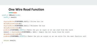
One Wire Read Function
C++ One Wire Read Bit Function
One Wire Reset/Presence Signal
C++ One Wire Reset/Presence Signal
Generating the Signals
● Software Only
○ Simply changing the direction and value of a GPIO and generating
required delay is sufficient
● With UART
○ Requires both TXD and RXD pins to be connected to the bus
○ Need tri-state or open-collector buffer so the slave can pull the
line low.
IC for UART Signals
DM74LS126A Tri-state Buffer IC
Generating UART Signals
● Baud rate is equivalent to bits/sec
● In order to transmit 1-wire framed data from UART platform we must
frame the data into the same time slots as in the polled implementation
● One UART data frame is used to generate one waveform bit of 1 wire data
or one RESET/Presence signal
Framing 1-Wire from UART
● To match waveform UART data
frame must match 1-Wire data
frame
● All UART signals initiate with a start
bit “0” or LOW
● To “Write 1” in one wire format all
bits in UART Frame after Start bit
must be HIGH or “1”
● To “Write 0” all bits in UART data
frame are “0” or LOW
● Stop bit is always HIGH or “1”
● “Read 1” Start bit is LOW and slave
writes bit “1” or HIGH in the
remaining data bits in UART frame
● “Read 0” start bit is LOW and the
slave drives the bus low by writing
“0” to the rest of the UART bit
pattern and drives the bus HIGH for
the STOP bit.
Generating One Wire Frame From UART
Reset/Presence Signal with UART
● UART bits 0-3 are LOW, 4 is HIGH, and Slave writes UART bits 5,6,&7
LOW
● Stop bit for this signal is HIGH
Overall Communication process
All 1-Wire devices follow this basic sequence(MUST FOLLOW):
1. The Master sends the Reset pulse.
2. The Slave(s) respond with a Presence pulse.
3. Master sends a ROM command
4. Master sends a Memory command
ROM Commands
● All 1-Wire devices contain a 64 bit identifier stored in ROM
● ROM Commands address those 64 bit identifiers
● After bus master detects a presence pulse it can issue a ROM command to
detect how many slaves are on the bus, and which slave to address.
ROM Commands MAX31820
● Read ROM(33h)-Reads the ROM code of single slave device. If there are
multiple slave devices and the command is issued, data collision will occur.
● Skip ROM(CCh)-Sends data for addressing to all connected slave devices
● Match ROM(55h)-Is used to address individual slave devices on the bus
● Search ROM(F0h)-Is used to get the ID of slave devices if not known
Cyclic Redundancy Check
● CRC is used an every ROM command to check for data integrity.
● CRC - is an error detection code for digital networks.
● It sends a check value along with the data that is transmitted. This value is
determined by dividing the data by a nominal value and returning the
remainder.
● If once the data is received and the remainder value is not the same, after
the received data has been divided by the nominal value, then we know the
data has been corrupted.
How CRC works
● We can think of CRC as an 8 bit shift register with feedback
How CRC Works
● At the beginning of a 64 bit Read ROM command the CRC shift register has
an initial value of zero. CRC = 0x00
● The LSB of the 64 bit identifier is XORd with the LSB of the input data. In the
case of 64 bit identifiers the LSB is a family CRC code(ex: 0xA2). So after the
first byte of data has been processed the CRC register will contain the value
of the CRC code. CRC = 0xA2
● After the entire 64 bit identifier has been shifted into and out of the CRC
register the register should have a final value of 0x00 if no data was
corrupted. If data was corrupted we would have a value inside the CRC shift
register and the data would have to be retransmitted.
CRC Computation of 1-Wire(Look up Table)
1. Dallas Semiconductor Corp. provides a table for CRC calculations. This table
rapidly increase CRC calculations and can process entire bytes of data per
loop run.
2. CRC register is initially zero we then shift in the first byte of 64 bit ID into
register
3. Then we XOR the next byte of data with the CRC register
4. Using pgm_read_byte we point to the index of our table and set our CRC
register to that new value. We are indexing by the XORd value of the CRC
register and the input data.
5. We repeat steps 4 and 5 until we are done with all 64 bits or 8 bytes of our
ID.
6. If CRC is 0 then no data was corrupted else data has been corrupted.
CRC Function Code Example
CRC Look Up Method
This table shows how each byte of data gets shifted into our CRC register and how we
calculate the next index for our CRC value.
Overall Communication process
All 1-Wire devices follow this basic sequence(MUST FOLLOW):
1. The Master sends the Reset pulse.
2. The Slave(s) respond with a Presence pulse.
3. Master sends a ROM command
4. Master sends a Memory command
Memory Commands
● Are commands specific to slave devices or a class of devices
● They deal with the internal memory and registers of slave devices
● Therefore for each device memory commands are specific to that device
MAX31820 Memory Registers
● Memory commands specific to this device would address this device's internal memory
registers
● TH and TL would address BYTE 2 and BYTE 3 of the temperature sensors internal
scratchpad memory
MAX31820 - Ambient Temperature
Sensor
MAX31820 Configuration Registers
● Bits R1 and R0 control the resolution of the temperature reading
● Better resolution slower conversion time, and faster conversion time less
resolution
MAX31820 Function Command Set
Overall Communication process
All 1-Wire devices follow this basic sequence:
1. The Master sends the Reset pulse.
2. The Slave(s) respond with a Presence pulse.
3. Master sends a ROM command
4. Master sends a Memory command
1 Wire Digital Temperature Sensor Implementation
● Assemble this simple circuit, the resistor is needed for the idle state of the
bus(HIGH)
● Also because it will act as a pull up resistor
Step 1
Download Necessary Libraries
Step 2
● Download OneWire Arduino Library
● Download DallasTemperature Arduino
Library
● Place both libraries into your Arduino
library path
● Include both libraries in your C++ code
1 Wire Digital Temperature Sensor Implementation
Step 3 Arduino Code
OneWire and DallasTemperature functions
● OneWire oneWire(ONE_WIRE_BUS) - this is a data structure defined in the one
wire library
● DallasTemperature sensors(&oneWire) - this is another data structure defined in
the DallasTemperature library that is an array of 8 bytes.(that is why the structure
must be passed as a pointer)
OneWire and DallasTemperature functions
● sensors.begin - is a subroutine in the DallasTemperature library that
identifies the type of temperature sensor on the bus and initializes the type
of power supply the temperature sensors requires.
● sensors.requestTemperatures - sends a reset/presence signal to begin
communication with device. Once presence is detected skip ROM command
is sent because only one temperature sensor is on the bus. Then we issue a
memory command that begins to send data of the temperature back to the
master device.
● sensors.getTempCByIndex(0) - This function returns the temperature in
celsius detected by the temperature sensor. If device is disconnected
during process it will return “DEVICE_DISCONNECTED_C”.
OneWire and DallasTemperature functions
References
https://en.wikipedia.org/wiki/1-Wire
http://www.atmel.com/images/Atmel-2579-Dallas-1Wire-Master-on-tinyAVR-and-megaAVR_ApplicationNote_AVR318.pdf
https://www.maximintegrated.com/en/app-notes/index.mvp/id/126
https://forum.pjrc.com/threads/23939-Strange-behavior-on-the-Onewireslave-library?p=33608&viewfull=1#post33608
https://create.arduino.cc/projecthub/TheGadgetBoy/ds18b20-digital-temperature-sensor-and-arduino-9cc806
https://www.hacktronics.com/Tutorials/arduino-1-wire-address-finder.html
https://en.wikipedia.org/wiki/Cyclic_redundancy_check
https://www.maximintegrated.com/en/app-notes/index.mvp/id/27
https://www.maximintegrated.com/en/products/1-wire/flash/overview/
Questions
1. How long are the time divisions of each bit level command?
2. What is the Idle state of the bus line?
3. What are the types of implementations of one wire?
4. Which implementation requires external hardware?
5. How does the master know there is a slave device connected?
6. Where are the 64 bit IDs of connected devices stored?
7. Which signal takes more than 1 time slot to transmit?
8. What device is needed for one wire UART?
9. What is the waveform of the write 1 signal?
10. Can data be both transmitted and received simultaneously by the one wire
protocol?
Answers
1. 60 microseconds
2. HIGH
3. Polled, UART(interrupt driven)
4. UART
5. Presence signal
6. ROM
7. Reset/Presence Signal
8. Tri-state buffer
9. Draw
10. No

More Related Content

What's hot

States machines (1)
States machines (1)States machines (1)
States machines (1)
omar bllaouhamou
 
Raspberry Pi 3 + UART/Bluetooth issues
Raspberry Pi 3 + UART/Bluetooth issuesRaspberry Pi 3 + UART/Bluetooth issues
Raspberry Pi 3 + UART/Bluetooth issues
yeokm1
 
Presentaion fpga µc µp quelles est la solution
Presentaion  fpga µc µp quelles est la solutionPresentaion  fpga µc µp quelles est la solution
Presentaion fpga µc µp quelles est la solution
Cynapsys It Hotspot
 
Đề tài: Thiết kế mạch chuyển đổi DAC 16 bít sử dụng vi mạch TDA
Đề tài: Thiết kế mạch chuyển đổi DAC 16 bít sử dụng vi mạch TDAĐề tài: Thiết kế mạch chuyển đổi DAC 16 bít sử dụng vi mạch TDA
Đề tài: Thiết kế mạch chuyển đổi DAC 16 bít sử dụng vi mạch TDA
Dịch vụ viết bài trọn gói ZALO 0917193864
 
x86 architecture
x86 architecturex86 architecture
x86 architecture
i i
 
Fao fraisage catia
Fao fraisage catiaFao fraisage catia
Fao fraisage catia
sarah Benmerzouk
 
Qemu JIT Code Generator and System Emulation
Qemu JIT Code Generator and System EmulationQemu JIT Code Generator and System Emulation
Qemu JIT Code Generator and System Emulation
National Cheng Kung University
 
Microcontrôleur PIC Microchip part1/2
Microcontrôleur PIC Microchip part1/2Microcontrôleur PIC Microchip part1/2
Microcontrôleur PIC Microchip part1/2
Mohammed Lamghari
 
4 STM32's SysTick.ppt
4 STM32's SysTick.ppt4 STM32's SysTick.ppt
4 STM32's SysTick.ppt
MdRayhanTanvir
 
Giáo trình vi điều khiển PIC
Giáo trình vi điều khiển PICGiáo trình vi điều khiển PIC
Giáo trình vi điều khiển PIC
Trung Thanh Nguyen
 
Đề tài: Mô phỏng động cơ đồng bộ nam châm vĩnh cửu, HAY
Đề tài: Mô phỏng động cơ đồng bộ nam châm vĩnh cửu, HAYĐề tài: Mô phỏng động cơ đồng bộ nam châm vĩnh cửu, HAY
Đề tài: Mô phỏng động cơ đồng bộ nam châm vĩnh cửu, HAY
Dịch vụ viết bài trọn gói ZALO 0917193864
 
Andes open cl for RISC-V
Andes open cl for RISC-VAndes open cl for RISC-V
Andes open cl for RISC-V
RISC-V International
 
ARM and SoC Traning Part I -- Overview
ARM and SoC Traning Part I -- OverviewARM and SoC Traning Part I -- Overview
ARM and SoC Traning Part I -- Overview
National Cheng Kung University
 
Bascules
BasculesBascules
Bascules
Soufiane Aggour
 
Bài Giảng Vi Xử Lý PIT
Bài Giảng Vi Xử Lý PITBài Giảng Vi Xử Lý PIT
Bài Giảng Vi Xử Lý PIT
Ngô Doãn Tình
 
Vhdl
VhdlVhdl
Vhdl
lionking
 
khởi động từ
khởi động từkhởi động từ
khởi động từ
Nam Dinh Hong
 
Advanced C - Part 3
Advanced C - Part 3Advanced C - Part 3

What's hot (20)

States machines (1)
States machines (1)States machines (1)
States machines (1)
 
Raspberry Pi 3 + UART/Bluetooth issues
Raspberry Pi 3 + UART/Bluetooth issuesRaspberry Pi 3 + UART/Bluetooth issues
Raspberry Pi 3 + UART/Bluetooth issues
 
Presentaion fpga µc µp quelles est la solution
Presentaion  fpga µc µp quelles est la solutionPresentaion  fpga µc µp quelles est la solution
Presentaion fpga µc µp quelles est la solution
 
Đề tài: Thiết kế mạch chuyển đổi DAC 16 bít sử dụng vi mạch TDA
Đề tài: Thiết kế mạch chuyển đổi DAC 16 bít sử dụng vi mạch TDAĐề tài: Thiết kế mạch chuyển đổi DAC 16 bít sử dụng vi mạch TDA
Đề tài: Thiết kế mạch chuyển đổi DAC 16 bít sử dụng vi mạch TDA
 
x86 architecture
x86 architecturex86 architecture
x86 architecture
 
Ch6 pal fpla
Ch6 pal fplaCh6 pal fpla
Ch6 pal fpla
 
Fao fraisage catia
Fao fraisage catiaFao fraisage catia
Fao fraisage catia
 
Qemu JIT Code Generator and System Emulation
Qemu JIT Code Generator and System EmulationQemu JIT Code Generator and System Emulation
Qemu JIT Code Generator and System Emulation
 
Microcontrôleur PIC Microchip part1/2
Microcontrôleur PIC Microchip part1/2Microcontrôleur PIC Microchip part1/2
Microcontrôleur PIC Microchip part1/2
 
4 STM32's SysTick.ppt
4 STM32's SysTick.ppt4 STM32's SysTick.ppt
4 STM32's SysTick.ppt
 
Giáo trình vi điều khiển PIC
Giáo trình vi điều khiển PICGiáo trình vi điều khiển PIC
Giáo trình vi điều khiển PIC
 
Đề tài: Mô phỏng động cơ đồng bộ nam châm vĩnh cửu, HAY
Đề tài: Mô phỏng động cơ đồng bộ nam châm vĩnh cửu, HAYĐề tài: Mô phỏng động cơ đồng bộ nam châm vĩnh cửu, HAY
Đề tài: Mô phỏng động cơ đồng bộ nam châm vĩnh cửu, HAY
 
Andes open cl for RISC-V
Andes open cl for RISC-VAndes open cl for RISC-V
Andes open cl for RISC-V
 
ARM and SoC Traning Part I -- Overview
ARM and SoC Traning Part I -- OverviewARM and SoC Traning Part I -- Overview
ARM and SoC Traning Part I -- Overview
 
Bascules
BasculesBascules
Bascules
 
Bài Giảng Vi Xử Lý PIT
Bài Giảng Vi Xử Lý PITBài Giảng Vi Xử Lý PIT
Bài Giảng Vi Xử Lý PIT
 
Vhdl
VhdlVhdl
Vhdl
 
khởi động từ
khởi động từkhởi động từ
khởi động từ
 
Advanced C - Part 3
Advanced C - Part 3Advanced C - Part 3
Advanced C - Part 3
 
Pic 16 F84 A
Pic 16 F84 APic 16 F84 A
Pic 16 F84 A
 

Similar to One-Wire-Serial-Communication.pdf

Embedded systems and robotics by scmandota
Embedded systems and robotics by scmandotaEmbedded systems and robotics by scmandota
Embedded systems and robotics by scmandota
scmandota
 
Assembler4
Assembler4Assembler4
Assembler4
Omar Sanchez
 
Digital logic-formula-notes-final-1
Digital logic-formula-notes-final-1Digital logic-formula-notes-final-1
Digital logic-formula-notes-final-1
Kshitij Singh
 
I2 c and mpu6050 basics
I2 c and mpu6050 basicsI2 c and mpu6050 basics
I2 c and mpu6050 basics
ironstein1994
 
Universal synchronous asynchronous receiver transmitter(usart) and AtoD Coverter
Universal synchronous asynchronous receiver transmitter(usart) and AtoD CoverterUniversal synchronous asynchronous receiver transmitter(usart) and AtoD Coverter
Universal synchronous asynchronous receiver transmitter(usart) and AtoD Coverter
Tejas Shetye
 
Training Report on embedded Systems and Robotics
Training Report on embedded  Systems and RoboticsTraining Report on embedded  Systems and Robotics
Training Report on embedded Systems and Robotics
NIT Raipur
 
communication interfaces-Embedded real time systems
communication interfaces-Embedded real time systemscommunication interfaces-Embedded real time systems
communication interfaces-Embedded real time systems
Raghunath reddy
 
Communication protocols - Embedded Systems
Communication protocols - Embedded SystemsCommunication protocols - Embedded Systems
Communication protocols - Embedded Systems
Emertxe Information Technologies Pvt Ltd
 
lesson01.ppt
lesson01.pptlesson01.ppt
lesson01.ppt
SushmaHiremath17
 
Design and Fabrication of 4-bit processor
Design and Fabrication of  4-bit processorDesign and Fabrication of  4-bit processor
Design and Fabrication of 4-bit processor
Priyatham Bollimpalli
 
Raspberry Pi - Lecture 3 Embedded Communication Protocols
Raspberry Pi - Lecture 3 Embedded Communication ProtocolsRaspberry Pi - Lecture 3 Embedded Communication Protocols
Raspberry Pi - Lecture 3 Embedded Communication Protocols
Mohamed Abdallah
 
Lect 3 ARM PROCESSOR ARCHITECTURE
Lect 3  ARM PROCESSOR ARCHITECTURE Lect 3  ARM PROCESSOR ARCHITECTURE
Lect 3 ARM PROCESSOR ARCHITECTURE
Dr.YNM
 
Lecture 10 (serial communication)
Lecture 10 (serial communication)Lecture 10 (serial communication)
Lecture 10 (serial communication)
cairo university
 
Introduction to embedded systems
Introduction to embedded systemsIntroduction to embedded systems
Introduction to embedded systems
Игорь Медведев
 
Micro c lab8(serial communication)
Micro c lab8(serial communication)Micro c lab8(serial communication)
Micro c lab8(serial communication)
Mashood
 
PIC 16F877 micro controller by Gaurav raikar
PIC 16F877 micro controller by Gaurav raikarPIC 16F877 micro controller by Gaurav raikar
PIC 16F877 micro controller by Gaurav raikar
GauravRaikar3
 
Pentium processor
Pentium processorPentium processor
Pentium processor
Pranjali Deshmukh
 
Industrial training report of embedded system and robotics
Industrial training report of embedded system and roboticsIndustrial training report of embedded system and robotics
Industrial training report of embedded system and robotics
Pallavi Bharti
 
Computer System and Architecture
Computer System and ArchitectureComputer System and Architecture
Computer System and Architecture
sarfraz1411
 
8255.pdf
8255.pdf8255.pdf
8255.pdf
someshdash1
 

Similar to One-Wire-Serial-Communication.pdf (20)

Embedded systems and robotics by scmandota
Embedded systems and robotics by scmandotaEmbedded systems and robotics by scmandota
Embedded systems and robotics by scmandota
 
Assembler4
Assembler4Assembler4
Assembler4
 
Digital logic-formula-notes-final-1
Digital logic-formula-notes-final-1Digital logic-formula-notes-final-1
Digital logic-formula-notes-final-1
 
I2 c and mpu6050 basics
I2 c and mpu6050 basicsI2 c and mpu6050 basics
I2 c and mpu6050 basics
 
Universal synchronous asynchronous receiver transmitter(usart) and AtoD Coverter
Universal synchronous asynchronous receiver transmitter(usart) and AtoD CoverterUniversal synchronous asynchronous receiver transmitter(usart) and AtoD Coverter
Universal synchronous asynchronous receiver transmitter(usart) and AtoD Coverter
 
Training Report on embedded Systems and Robotics
Training Report on embedded  Systems and RoboticsTraining Report on embedded  Systems and Robotics
Training Report on embedded Systems and Robotics
 
communication interfaces-Embedded real time systems
communication interfaces-Embedded real time systemscommunication interfaces-Embedded real time systems
communication interfaces-Embedded real time systems
 
Communication protocols - Embedded Systems
Communication protocols - Embedded SystemsCommunication protocols - Embedded Systems
Communication protocols - Embedded Systems
 
lesson01.ppt
lesson01.pptlesson01.ppt
lesson01.ppt
 
Design and Fabrication of 4-bit processor
Design and Fabrication of  4-bit processorDesign and Fabrication of  4-bit processor
Design and Fabrication of 4-bit processor
 
Raspberry Pi - Lecture 3 Embedded Communication Protocols
Raspberry Pi - Lecture 3 Embedded Communication ProtocolsRaspberry Pi - Lecture 3 Embedded Communication Protocols
Raspberry Pi - Lecture 3 Embedded Communication Protocols
 
Lect 3 ARM PROCESSOR ARCHITECTURE
Lect 3  ARM PROCESSOR ARCHITECTURE Lect 3  ARM PROCESSOR ARCHITECTURE
Lect 3 ARM PROCESSOR ARCHITECTURE
 
Lecture 10 (serial communication)
Lecture 10 (serial communication)Lecture 10 (serial communication)
Lecture 10 (serial communication)
 
Introduction to embedded systems
Introduction to embedded systemsIntroduction to embedded systems
Introduction to embedded systems
 
Micro c lab8(serial communication)
Micro c lab8(serial communication)Micro c lab8(serial communication)
Micro c lab8(serial communication)
 
PIC 16F877 micro controller by Gaurav raikar
PIC 16F877 micro controller by Gaurav raikarPIC 16F877 micro controller by Gaurav raikar
PIC 16F877 micro controller by Gaurav raikar
 
Pentium processor
Pentium processorPentium processor
Pentium processor
 
Industrial training report of embedded system and robotics
Industrial training report of embedded system and roboticsIndustrial training report of embedded system and robotics
Industrial training report of embedded system and robotics
 
Computer System and Architecture
Computer System and ArchitectureComputer System and Architecture
Computer System and Architecture
 
8255.pdf
8255.pdf8255.pdf
8255.pdf
 

Recently uploaded

Epistemic Interaction - tuning interfaces to provide information for AI support
Epistemic Interaction - tuning interfaces to provide information for AI supportEpistemic Interaction - tuning interfaces to provide information for AI support
Epistemic Interaction - tuning interfaces to provide information for AI support
Alan Dix
 
How world-class product teams are winning in the AI era by CEO and Founder, P...
How world-class product teams are winning in the AI era by CEO and Founder, P...How world-class product teams are winning in the AI era by CEO and Founder, P...
How world-class product teams are winning in the AI era by CEO and Founder, P...
Product School
 
Designing Great Products: The Power of Design and Leadership by Chief Designe...
Designing Great Products: The Power of Design and Leadership by Chief Designe...Designing Great Products: The Power of Design and Leadership by Chief Designe...
Designing Great Products: The Power of Design and Leadership by Chief Designe...
Product School
 
GDG Cloud Southlake #33: Boule & Rebala: Effective AppSec in SDLC using Deplo...
GDG Cloud Southlake #33: Boule & Rebala: Effective AppSec in SDLC using Deplo...GDG Cloud Southlake #33: Boule & Rebala: Effective AppSec in SDLC using Deplo...
GDG Cloud Southlake #33: Boule & Rebala: Effective AppSec in SDLC using Deplo...
James Anderson
 
Bits & Pixels using AI for Good.........
Bits & Pixels using AI for Good.........Bits & Pixels using AI for Good.........
Bits & Pixels using AI for Good.........
Alison B. Lowndes
 
From Siloed Products to Connected Ecosystem: Building a Sustainable and Scala...
From Siloed Products to Connected Ecosystem: Building a Sustainable and Scala...From Siloed Products to Connected Ecosystem: Building a Sustainable and Scala...
From Siloed Products to Connected Ecosystem: Building a Sustainable and Scala...
Product School
 
Monitoring Java Application Security with JDK Tools and JFR Events
Monitoring Java Application Security with JDK Tools and JFR EventsMonitoring Java Application Security with JDK Tools and JFR Events
Monitoring Java Application Security with JDK Tools and JFR Events
Ana-Maria Mihalceanu
 
Unsubscribed: Combat Subscription Fatigue With a Membership Mentality by Head...
Unsubscribed: Combat Subscription Fatigue With a Membership Mentality by Head...Unsubscribed: Combat Subscription Fatigue With a Membership Mentality by Head...
Unsubscribed: Combat Subscription Fatigue With a Membership Mentality by Head...
Product School
 
From Daily Decisions to Bottom Line: Connecting Product Work to Revenue by VP...
From Daily Decisions to Bottom Line: Connecting Product Work to Revenue by VP...From Daily Decisions to Bottom Line: Connecting Product Work to Revenue by VP...
From Daily Decisions to Bottom Line: Connecting Product Work to Revenue by VP...
Product School
 
Connector Corner: Automate dynamic content and events by pushing a button
Connector Corner: Automate dynamic content and events by pushing a buttonConnector Corner: Automate dynamic content and events by pushing a button
Connector Corner: Automate dynamic content and events by pushing a button
DianaGray10
 
Kubernetes & AI - Beauty and the Beast !?! @KCD Istanbul 2024
Kubernetes & AI - Beauty and the Beast !?! @KCD Istanbul 2024Kubernetes & AI - Beauty and the Beast !?! @KCD Istanbul 2024
Kubernetes & AI - Beauty and the Beast !?! @KCD Istanbul 2024
Tobias Schneck
 
Encryption in Microsoft 365 - ExpertsLive Netherlands 2024
Encryption in Microsoft 365 - ExpertsLive Netherlands 2024Encryption in Microsoft 365 - ExpertsLive Netherlands 2024
Encryption in Microsoft 365 - ExpertsLive Netherlands 2024
Albert Hoitingh
 
Generating a custom Ruby SDK for your web service or Rails API using Smithy
Generating a custom Ruby SDK for your web service or Rails API using SmithyGenerating a custom Ruby SDK for your web service or Rails API using Smithy
Generating a custom Ruby SDK for your web service or Rails API using Smithy
g2nightmarescribd
 
Slack (or Teams) Automation for Bonterra Impact Management (fka Social Soluti...
Slack (or Teams) Automation for Bonterra Impact Management (fka Social Soluti...Slack (or Teams) Automation for Bonterra Impact Management (fka Social Soluti...
Slack (or Teams) Automation for Bonterra Impact Management (fka Social Soluti...
Jeffrey Haguewood
 
PCI PIN Basics Webinar from the Controlcase Team
PCI PIN Basics Webinar from the Controlcase TeamPCI PIN Basics Webinar from the Controlcase Team
PCI PIN Basics Webinar from the Controlcase Team
ControlCase
 
Empowering NextGen Mobility via Large Action Model Infrastructure (LAMI): pav...
Empowering NextGen Mobility via Large Action Model Infrastructure (LAMI): pav...Empowering NextGen Mobility via Large Action Model Infrastructure (LAMI): pav...
Empowering NextGen Mobility via Large Action Model Infrastructure (LAMI): pav...
Thierry Lestable
 
AI for Every Business: Unlocking Your Product's Universal Potential by VP of ...
AI for Every Business: Unlocking Your Product's Universal Potential by VP of ...AI for Every Business: Unlocking Your Product's Universal Potential by VP of ...
AI for Every Business: Unlocking Your Product's Universal Potential by VP of ...
Product School
 
Dev Dives: Train smarter, not harder – active learning and UiPath LLMs for do...
Dev Dives: Train smarter, not harder – active learning and UiPath LLMs for do...Dev Dives: Train smarter, not harder – active learning and UiPath LLMs for do...
Dev Dives: Train smarter, not harder – active learning and UiPath LLMs for do...
UiPathCommunity
 
FIDO Alliance Osaka Seminar: Overview.pdf
FIDO Alliance Osaka Seminar: Overview.pdfFIDO Alliance Osaka Seminar: Overview.pdf
FIDO Alliance Osaka Seminar: Overview.pdf
FIDO Alliance
 
FIDO Alliance Osaka Seminar: Passkeys and the Road Ahead.pdf
FIDO Alliance Osaka Seminar: Passkeys and the Road Ahead.pdfFIDO Alliance Osaka Seminar: Passkeys and the Road Ahead.pdf
FIDO Alliance Osaka Seminar: Passkeys and the Road Ahead.pdf
FIDO Alliance
 

Recently uploaded (20)

Epistemic Interaction - tuning interfaces to provide information for AI support
Epistemic Interaction - tuning interfaces to provide information for AI supportEpistemic Interaction - tuning interfaces to provide information for AI support
Epistemic Interaction - tuning interfaces to provide information for AI support
 
How world-class product teams are winning in the AI era by CEO and Founder, P...
How world-class product teams are winning in the AI era by CEO and Founder, P...How world-class product teams are winning in the AI era by CEO and Founder, P...
How world-class product teams are winning in the AI era by CEO and Founder, P...
 
Designing Great Products: The Power of Design and Leadership by Chief Designe...
Designing Great Products: The Power of Design and Leadership by Chief Designe...Designing Great Products: The Power of Design and Leadership by Chief Designe...
Designing Great Products: The Power of Design and Leadership by Chief Designe...
 
GDG Cloud Southlake #33: Boule & Rebala: Effective AppSec in SDLC using Deplo...
GDG Cloud Southlake #33: Boule & Rebala: Effective AppSec in SDLC using Deplo...GDG Cloud Southlake #33: Boule & Rebala: Effective AppSec in SDLC using Deplo...
GDG Cloud Southlake #33: Boule & Rebala: Effective AppSec in SDLC using Deplo...
 
Bits & Pixels using AI for Good.........
Bits & Pixels using AI for Good.........Bits & Pixels using AI for Good.........
Bits & Pixels using AI for Good.........
 
From Siloed Products to Connected Ecosystem: Building a Sustainable and Scala...
From Siloed Products to Connected Ecosystem: Building a Sustainable and Scala...From Siloed Products to Connected Ecosystem: Building a Sustainable and Scala...
From Siloed Products to Connected Ecosystem: Building a Sustainable and Scala...
 
Monitoring Java Application Security with JDK Tools and JFR Events
Monitoring Java Application Security with JDK Tools and JFR EventsMonitoring Java Application Security with JDK Tools and JFR Events
Monitoring Java Application Security with JDK Tools and JFR Events
 
Unsubscribed: Combat Subscription Fatigue With a Membership Mentality by Head...
Unsubscribed: Combat Subscription Fatigue With a Membership Mentality by Head...Unsubscribed: Combat Subscription Fatigue With a Membership Mentality by Head...
Unsubscribed: Combat Subscription Fatigue With a Membership Mentality by Head...
 
From Daily Decisions to Bottom Line: Connecting Product Work to Revenue by VP...
From Daily Decisions to Bottom Line: Connecting Product Work to Revenue by VP...From Daily Decisions to Bottom Line: Connecting Product Work to Revenue by VP...
From Daily Decisions to Bottom Line: Connecting Product Work to Revenue by VP...
 
Connector Corner: Automate dynamic content and events by pushing a button
Connector Corner: Automate dynamic content and events by pushing a buttonConnector Corner: Automate dynamic content and events by pushing a button
Connector Corner: Automate dynamic content and events by pushing a button
 
Kubernetes & AI - Beauty and the Beast !?! @KCD Istanbul 2024
Kubernetes & AI - Beauty and the Beast !?! @KCD Istanbul 2024Kubernetes & AI - Beauty and the Beast !?! @KCD Istanbul 2024
Kubernetes & AI - Beauty and the Beast !?! @KCD Istanbul 2024
 
Encryption in Microsoft 365 - ExpertsLive Netherlands 2024
Encryption in Microsoft 365 - ExpertsLive Netherlands 2024Encryption in Microsoft 365 - ExpertsLive Netherlands 2024
Encryption in Microsoft 365 - ExpertsLive Netherlands 2024
 
Generating a custom Ruby SDK for your web service or Rails API using Smithy
Generating a custom Ruby SDK for your web service or Rails API using SmithyGenerating a custom Ruby SDK for your web service or Rails API using Smithy
Generating a custom Ruby SDK for your web service or Rails API using Smithy
 
Slack (or Teams) Automation for Bonterra Impact Management (fka Social Soluti...
Slack (or Teams) Automation for Bonterra Impact Management (fka Social Soluti...Slack (or Teams) Automation for Bonterra Impact Management (fka Social Soluti...
Slack (or Teams) Automation for Bonterra Impact Management (fka Social Soluti...
 
PCI PIN Basics Webinar from the Controlcase Team
PCI PIN Basics Webinar from the Controlcase TeamPCI PIN Basics Webinar from the Controlcase Team
PCI PIN Basics Webinar from the Controlcase Team
 
Empowering NextGen Mobility via Large Action Model Infrastructure (LAMI): pav...
Empowering NextGen Mobility via Large Action Model Infrastructure (LAMI): pav...Empowering NextGen Mobility via Large Action Model Infrastructure (LAMI): pav...
Empowering NextGen Mobility via Large Action Model Infrastructure (LAMI): pav...
 
AI for Every Business: Unlocking Your Product's Universal Potential by VP of ...
AI for Every Business: Unlocking Your Product's Universal Potential by VP of ...AI for Every Business: Unlocking Your Product's Universal Potential by VP of ...
AI for Every Business: Unlocking Your Product's Universal Potential by VP of ...
 
Dev Dives: Train smarter, not harder – active learning and UiPath LLMs for do...
Dev Dives: Train smarter, not harder – active learning and UiPath LLMs for do...Dev Dives: Train smarter, not harder – active learning and UiPath LLMs for do...
Dev Dives: Train smarter, not harder – active learning and UiPath LLMs for do...
 
FIDO Alliance Osaka Seminar: Overview.pdf
FIDO Alliance Osaka Seminar: Overview.pdfFIDO Alliance Osaka Seminar: Overview.pdf
FIDO Alliance Osaka Seminar: Overview.pdf
 
FIDO Alliance Osaka Seminar: Passkeys and the Road Ahead.pdf
FIDO Alliance Osaka Seminar: Passkeys and the Road Ahead.pdfFIDO Alliance Osaka Seminar: Passkeys and the Road Ahead.pdf
FIDO Alliance Osaka Seminar: Passkeys and the Road Ahead.pdf
 

One-Wire-Serial-Communication.pdf

  • 1. What is One Wire Serial Communication ● Serial data transmission over one wire(duh) ● Great for cheap applications that don't require high speed data transfer ● In theory, all AVR processors can handle One Wire Communication ● Timing is extremely important ○ The only way to discern signals from other signals
  • 2. How Does it Work? ● Two basic implementations ○ Polled Implementations(software only) ○ Interrupt driven (counter required) ● Dallas 1-Wire Protocol ○ Designed by the Dallas Semiconductor Corporation ○ Can use either interrupt driven or polled implementations ○ Polled requires no external hardware ○ Half Duplex(transmitting or receiving not Both simultaneously)
  • 3. Dallas 1-Wire ● Signal is idle High, need pull up resistor ● Signaling is divided into time slots of 60µs ● Master initiates every communication ○ Regardless of direction ● 5 basic signals: (Write 1, Write 0, Read, Reset, Presence) ● LSB sent first
  • 4. Overall Communication process All 1-Wire devices follow this basic sequence: 1. The Master sends the Reset pulse. 2. The Slave(s) respond with a Presence pulse. 3. Master sends a ROM command 4. Master sends a Memory command
  • 5. How To Send Bits ● In order to send bits in OW protocol it requires precise timing and precise waveforms ● Errors in these waveforms, or the timing can deliver corrupt data and requires digital error checking
  • 6. Bus Signals ● Write 1 ○ The Master pulls the bus low for 15µs then releases for remainder of 60µs window
  • 7. Bus Signals Continued ● Write 0 ○ The master pulls the bus low for 60µs ● Read ○ Master pulls bus low for 1 to 15µs ○ The slave then releases the line if it wants to write 1 or keeps the line low for write 0 for remainder of 60 us window.
  • 8. Timing Diagram of OW Signals
  • 9. Reset/Presence Signal ● Reset Signal ○ The master pulls the line low for 480µs and then releases it ○ If slave is present then the presence signal should be seen ○ If no presence signal is detected there is no device connected ● Presence Signal ○ After the Reset Signal has been sent it is the slave that must pull the line low for 60µs ○ Must pull the line low within 60µs
  • 11. Generating Signals through Software ● Define delay values ● Define our BUS pin ● Initialize the bus as an output
  • 13. One Wire Write function
  • 14. C++ One Wire Write function
  • 15. One Wire Read Function
  • 16. C++ One Wire Read Bit Function
  • 18. C++ One Wire Reset/Presence Signal
  • 19. Generating the Signals ● Software Only ○ Simply changing the direction and value of a GPIO and generating required delay is sufficient ● With UART ○ Requires both TXD and RXD pins to be connected to the bus ○ Need tri-state or open-collector buffer so the slave can pull the line low.
  • 20. IC for UART Signals DM74LS126A Tri-state Buffer IC
  • 21. Generating UART Signals ● Baud rate is equivalent to bits/sec ● In order to transmit 1-wire framed data from UART platform we must frame the data into the same time slots as in the polled implementation ● One UART data frame is used to generate one waveform bit of 1 wire data or one RESET/Presence signal
  • 22. Framing 1-Wire from UART ● To match waveform UART data frame must match 1-Wire data frame ● All UART signals initiate with a start bit “0” or LOW ● To “Write 1” in one wire format all bits in UART Frame after Start bit must be HIGH or “1” ● To “Write 0” all bits in UART data frame are “0” or LOW ● Stop bit is always HIGH or “1”
  • 23. ● “Read 1” Start bit is LOW and slave writes bit “1” or HIGH in the remaining data bits in UART frame ● “Read 0” start bit is LOW and the slave drives the bus low by writing “0” to the rest of the UART bit pattern and drives the bus HIGH for the STOP bit. Generating One Wire Frame From UART
  • 24. Reset/Presence Signal with UART ● UART bits 0-3 are LOW, 4 is HIGH, and Slave writes UART bits 5,6,&7 LOW ● Stop bit for this signal is HIGH
  • 25. Overall Communication process All 1-Wire devices follow this basic sequence(MUST FOLLOW): 1. The Master sends the Reset pulse. 2. The Slave(s) respond with a Presence pulse. 3. Master sends a ROM command 4. Master sends a Memory command
  • 26. ROM Commands ● All 1-Wire devices contain a 64 bit identifier stored in ROM ● ROM Commands address those 64 bit identifiers ● After bus master detects a presence pulse it can issue a ROM command to detect how many slaves are on the bus, and which slave to address.
  • 27. ROM Commands MAX31820 ● Read ROM(33h)-Reads the ROM code of single slave device. If there are multiple slave devices and the command is issued, data collision will occur. ● Skip ROM(CCh)-Sends data for addressing to all connected slave devices ● Match ROM(55h)-Is used to address individual slave devices on the bus ● Search ROM(F0h)-Is used to get the ID of slave devices if not known
  • 28. Cyclic Redundancy Check ● CRC is used an every ROM command to check for data integrity. ● CRC - is an error detection code for digital networks. ● It sends a check value along with the data that is transmitted. This value is determined by dividing the data by a nominal value and returning the remainder. ● If once the data is received and the remainder value is not the same, after the received data has been divided by the nominal value, then we know the data has been corrupted.
  • 29. How CRC works ● We can think of CRC as an 8 bit shift register with feedback
  • 30. How CRC Works ● At the beginning of a 64 bit Read ROM command the CRC shift register has an initial value of zero. CRC = 0x00 ● The LSB of the 64 bit identifier is XORd with the LSB of the input data. In the case of 64 bit identifiers the LSB is a family CRC code(ex: 0xA2). So after the first byte of data has been processed the CRC register will contain the value of the CRC code. CRC = 0xA2 ● After the entire 64 bit identifier has been shifted into and out of the CRC register the register should have a final value of 0x00 if no data was corrupted. If data was corrupted we would have a value inside the CRC shift register and the data would have to be retransmitted.
  • 31. CRC Computation of 1-Wire(Look up Table) 1. Dallas Semiconductor Corp. provides a table for CRC calculations. This table rapidly increase CRC calculations and can process entire bytes of data per loop run. 2. CRC register is initially zero we then shift in the first byte of 64 bit ID into register 3. Then we XOR the next byte of data with the CRC register 4. Using pgm_read_byte we point to the index of our table and set our CRC register to that new value. We are indexing by the XORd value of the CRC register and the input data. 5. We repeat steps 4 and 5 until we are done with all 64 bits or 8 bytes of our ID. 6. If CRC is 0 then no data was corrupted else data has been corrupted.
  • 32. CRC Function Code Example
  • 33. CRC Look Up Method This table shows how each byte of data gets shifted into our CRC register and how we calculate the next index for our CRC value.
  • 34. Overall Communication process All 1-Wire devices follow this basic sequence(MUST FOLLOW): 1. The Master sends the Reset pulse. 2. The Slave(s) respond with a Presence pulse. 3. Master sends a ROM command 4. Master sends a Memory command
  • 35. Memory Commands ● Are commands specific to slave devices or a class of devices ● They deal with the internal memory and registers of slave devices ● Therefore for each device memory commands are specific to that device
  • 36. MAX31820 Memory Registers ● Memory commands specific to this device would address this device's internal memory registers ● TH and TL would address BYTE 2 and BYTE 3 of the temperature sensors internal scratchpad memory MAX31820 - Ambient Temperature Sensor
  • 37. MAX31820 Configuration Registers ● Bits R1 and R0 control the resolution of the temperature reading ● Better resolution slower conversion time, and faster conversion time less resolution
  • 39. Overall Communication process All 1-Wire devices follow this basic sequence: 1. The Master sends the Reset pulse. 2. The Slave(s) respond with a Presence pulse. 3. Master sends a ROM command 4. Master sends a Memory command
  • 40. 1 Wire Digital Temperature Sensor Implementation ● Assemble this simple circuit, the resistor is needed for the idle state of the bus(HIGH) ● Also because it will act as a pull up resistor Step 1
  • 41. Download Necessary Libraries Step 2 ● Download OneWire Arduino Library ● Download DallasTemperature Arduino Library ● Place both libraries into your Arduino library path ● Include both libraries in your C++ code 1 Wire Digital Temperature Sensor Implementation
  • 42. 1 Wire Digital Temperature Sensor Implementation Step 3 Arduino Code
  • 43. OneWire and DallasTemperature functions ● OneWire oneWire(ONE_WIRE_BUS) - this is a data structure defined in the one wire library ● DallasTemperature sensors(&oneWire) - this is another data structure defined in the DallasTemperature library that is an array of 8 bytes.(that is why the structure must be passed as a pointer)
  • 44. OneWire and DallasTemperature functions ● sensors.begin - is a subroutine in the DallasTemperature library that identifies the type of temperature sensor on the bus and initializes the type of power supply the temperature sensors requires. ● sensors.requestTemperatures - sends a reset/presence signal to begin communication with device. Once presence is detected skip ROM command is sent because only one temperature sensor is on the bus. Then we issue a memory command that begins to send data of the temperature back to the master device.
  • 45. ● sensors.getTempCByIndex(0) - This function returns the temperature in celsius detected by the temperature sensor. If device is disconnected during process it will return “DEVICE_DISCONNECTED_C”. OneWire and DallasTemperature functions
  • 47. Questions 1. How long are the time divisions of each bit level command? 2. What is the Idle state of the bus line? 3. What are the types of implementations of one wire? 4. Which implementation requires external hardware? 5. How does the master know there is a slave device connected? 6. Where are the 64 bit IDs of connected devices stored? 7. Which signal takes more than 1 time slot to transmit? 8. What device is needed for one wire UART? 9. What is the waveform of the write 1 signal? 10. Can data be both transmitted and received simultaneously by the one wire protocol?
  • 48. Answers 1. 60 microseconds 2. HIGH 3. Polled, UART(interrupt driven) 4. UART 5. Presence signal 6. ROM 7. Reset/Presence Signal 8. Tri-state buffer 9. Draw 10. No