This document provides operation instructions for RGL and RBGL liftgates with 2000-6000 lb capacity. It begins with safety information, then provides terminology to identify liftgate components. The main section provides instructions for loading and unloading the platform in both the dock and transit positions, including raising, lowering, opening, and closing the platform. It emphasizes safe and proper use, such as loading positions, and securing the safety chains when in transit.
10 datos curiosos sobre el transporte marítimoiContainers
¿Sabías que el transporte marítimo representa el 90% de los envíos de comercio mundial?,¿o que 20 millones de contenedores están cruzando los mares en este momento?
Aquí tienes 10 datos curiosos sobre transporte marítimo que realmente te costará creer.
Este documento hace referencia de todos los requerimientos que se deben cumplir para la planificación zonas de almacenamientos desde el punto de vista de la Ingeniería Civil.
Recurso para Biología y Geología, adaptable tanto para 3ESO como para 1 BAC. Se compara una célula con una ciudad. Soluciones en www.larubiscoeslomas.com/analogia-celula-ciudad/
This is the Highly Detailed factory service repair manual for theCATERPILLAR CAT GC55K FORKLIFT LIFT TRUCKS, this Service Manual has detailed illustrations as well as step by step instructions,It is 100 percents complete and intact. they are specifically written for the do-it-yourself-er as well as the experienced mechanic.CATERPILLAR CAT GC55K FORKLIFT LIFT TRUCKS Service Repair Workshop Manual provides step-by-step instructions based on the complete dis-assembly of the machine. It is this level of detail, along with hundreds of photos and illustrations, that guide the reader through each service and repair procedure. Complete download comes in pdf format which can work under all PC based windows operating system and Mac also, All pages are printable. Using this repair manual is an inexpensive way to keep your vehicle working properly.
Service Repair Manual Covers:
Chassis and Mast: Foreword
Chassis and Mast: General Information
Chassis and Mast: Cooling System
Chassis and Mast: Electrical System
Chassis and Mast: Power Train
Chassis and Mast: Power shift Transmission
Chassis and Mast: Front Axle and Reduction Differential
Chassis and Mast: Rear Axle
Chassis and Mast: Brake System
Chassis and Mast: Steering System
Chassis and Mast: Hydraulic System
Chassis and Mast: Mast and Forks
Chassis and Mast: Service Data
Chassis and Mast: Schematics
Options Supplement: Foreword
Options Supplement: Safety
Options Supplement: Rear Combination Kit
Options Supplement: Warning Lamp Kit
Options Supplement: Working Lamp Kit
Options Supplement: Creeper Speed Kit
Options Supplement: Foot Directional Control Group
Options Supplement: Engine Shutdown Kit (LPG Models Only)
Options Supplement: Enclosed Alternator Field Kit
Options Supplement: Disconnect Switch Kit
Options Supplement: UL Fuel Cap Kit (Gasoline models only)
Options Supplement: Key Kit
Options Supplement: Back Buzzer Kit
Options Supplement: Dual Element Air Cleaner
Options Supplement: Dust and Foundry Kit
Options Supplement: Back Mirror Kit
File Format: PDF
Compatible: All Versions of Windows & Mac
Language: English
Requirements: Adobe PDF Reader
NO waiting, Buy from responsible seller and get INSTANT DOWNLOAD, Without wasting your hard-owned money on uncertainty or surprise! All pages are is great to haveCATERPILLAR CAT GC55K FORKLIFT LIFT TRUCKS Service Repair Workshop Manual.
Looking for some other Service Repair Manual,please check:
https://www.aservicemanualpdf.com/
Thanks for visiting!
Caterpillar Cat DP25K MC Forklift Lift Trucks Service Repair Manual SN:ET18B-...jksebmdmn
This is the Highly Detailed factory service repair manual for theCATERPILLAR CAT DP25K MC FORKLIFT LIFT TRUCKS , this Service Manual has detailed illustrations as well as step by step instructions,It is 100 percents complete and intact. they are specifically written for the do-it-yourself-er as well as the experienced mechanic.CATERPILLAR CAT DP25K MC FORKLIFT LIFT TRUCKS Service Repair Workshop Manual provides step-by-step instructions based on the complete dis-assembly of the machine. It is this level of detail, along with hundreds of photos and illustrations, that guide the reader through each service and repair procedure. Complete download comes in pdf format which can work under all PC based windows operating system and Mac also, All pages are printable. Using this repair manual is an inexpensive way to keep your vehicle working properly.
Service Repair Manual Covers:
General Information
Cooling System
Electrical System
Power Train
Power shift Transmission
Front Axle and Reduction Differential
Rear Axle
Brake System
Steering System
Hydraulic System
Mast and Fork
Service Data
Options
File Format: PDF
Compatible: All Versions of Windows & Mac
Language: English
Requirements: Adobe PDF Reader
NO waiting, Buy from responsible seller and get INSTANT DOWNLOAD, Without wasting your hard-owned money on uncertainty or surprise! All pages are is great to haveCATERPILLAR CAT DP25K MC FORKLIFT LIFT TRUCKS Service Repair Workshop Manual.
Looking for some other Service Repair Manual,please check:
https://www.aservicemanualpdf.com/
Thanks for visiting!
8
Caterpillar Cat DP20K MC Forklift Lift Trucks Service Repair Manual SN:ET18B-...fhjskemfmse
This is the Highly Detailed factory service repair manual for theCATERPILLAR CAT DP20K MC FORKLIFT LIFT TRUCKS, this Service Manual has detailed illustrations as well as step by step instructions,It is 100 percents complete and intact. they are specifically written for the do-it-yourself-er as well as the experienced mechanic.CATERPILLAR CAT DP20K MC FORKLIFT LIFT TRUCKS Service Repair Workshop Manual provides step-by-step instructions based on the complete dis-assembly of the machine. It is this level of detail, along with hundreds of photos and illustrations, that guide the reader through each service and repair procedure. Complete download comes in pdf format which can work under all PC based windows operating system and Mac also, All pages are printable. Using this repair manual is an inexpensive way to keep your vehicle working properly.
Service Repair Manual Covers:
General Information
Cooling System
Electrical System
Power Train
Power shift Transmission
Front Axle and Reduction Differential
Rear Axle
Brake System
Steering System
Hydraulic System
Mast and Fork
Service Data
Options
File Format: PDF
Compatible: All Versions of Windows & Mac
Language: English
Requirements: Adobe PDF Reader
NO waiting, Buy from responsible seller and get INSTANT DOWNLOAD, Without wasting your hard-owned money on uncertainty or surprise! All pages are is great to haveCATERPILLAR CAT DP20K MC FORKLIFT LIFT TRUCKS Service Repair Workshop Manual.
Looking for some other Service Repair Manual,please check:
https://www.aservicemanualpdf.com/
Thanks for visiting!
Hybrid optimization of pumped hydro system and solar- Engr. Abdul-Azeez.pdffxintegritypublishin
Advancements in technology unveil a myriad of electrical and electronic breakthroughs geared towards efficiently harnessing limited resources to meet human energy demands. The optimization of hybrid solar PV panels and pumped hydro energy supply systems plays a pivotal role in utilizing natural resources effectively. This initiative not only benefits humanity but also fosters environmental sustainability. The study investigated the design optimization of these hybrid systems, focusing on understanding solar radiation patterns, identifying geographical influences on solar radiation, formulating a mathematical model for system optimization, and determining the optimal configuration of PV panels and pumped hydro storage. Through a comparative analysis approach and eight weeks of data collection, the study addressed key research questions related to solar radiation patterns and optimal system design. The findings highlighted regions with heightened solar radiation levels, showcasing substantial potential for power generation and emphasizing the system's efficiency. Optimizing system design significantly boosted power generation, promoted renewable energy utilization, and enhanced energy storage capacity. The study underscored the benefits of optimizing hybrid solar PV panels and pumped hydro energy supply systems for sustainable energy usage. Optimizing the design of solar PV panels and pumped hydro energy supply systems as examined across diverse climatic conditions in a developing country, not only enhances power generation but also improves the integration of renewable energy sources and boosts energy storage capacities, particularly beneficial for less economically prosperous regions. Additionally, the study provides valuable insights for advancing energy research in economically viable areas. Recommendations included conducting site-specific assessments, utilizing advanced modeling tools, implementing regular maintenance protocols, and enhancing communication among system components.
Immunizing Image Classifiers Against Localized Adversary Attacksgerogepatton
This paper addresses the vulnerability of deep learning models, particularly convolutional neural networks
(CNN)s, to adversarial attacks and presents a proactive training technique designed to counter them. We
introduce a novel volumization algorithm, which transforms 2D images into 3D volumetric representations.
When combined with 3D convolution and deep curriculum learning optimization (CLO), itsignificantly improves
the immunity of models against localized universal attacks by up to 40%. We evaluate our proposed approach
using contemporary CNN architectures and the modified Canadian Institute for Advanced Research (CIFAR-10
and CIFAR-100) and ImageNet Large Scale Visual Recognition Challenge (ILSVRC12) datasets, showcasing
accuracy improvements over previous techniques. The results indicate that the combination of the volumetric
input and curriculum learning holds significant promise for mitigating adversarial attacks without necessitating
adversary training.
Explore the innovative world of trenchless pipe repair with our comprehensive guide, "The Benefits and Techniques of Trenchless Pipe Repair." This document delves into the modern methods of repairing underground pipes without the need for extensive excavation, highlighting the numerous advantages and the latest techniques used in the industry.
Learn about the cost savings, reduced environmental impact, and minimal disruption associated with trenchless technology. Discover detailed explanations of popular techniques such as pipe bursting, cured-in-place pipe (CIPP) lining, and directional drilling. Understand how these methods can be applied to various types of infrastructure, from residential plumbing to large-scale municipal systems.
Ideal for homeowners, contractors, engineers, and anyone interested in modern plumbing solutions, this guide provides valuable insights into why trenchless pipe repair is becoming the preferred choice for pipe rehabilitation. Stay informed about the latest advancements and best practices in the field.
Industrial Training at Shahjalal Fertilizer Company Limited (SFCL)MdTanvirMahtab2
This presentation is about the working procedure of Shahjalal Fertilizer Company Limited (SFCL). A Govt. owned Company of Bangladesh Chemical Industries Corporation under Ministry of Industries.
Student information management system project report ii.pdfKamal Acharya
Our project explains about the student management. This project mainly explains the various actions related to student details. This project shows some ease in adding, editing and deleting the student details. It also provides a less time consuming process for viewing, adding, editing and deleting the marks of the students.
Overview of the fundamental roles in Hydropower generation and the components involved in wider Electrical Engineering.
This paper presents the design and construction of hydroelectric dams from the hydrologist’s survey of the valley before construction, all aspects and involved disciplines, fluid dynamics, structural engineering, generation and mains frequency regulation to the very transmission of power through the network in the United Kingdom.
Author: Robbie Edward Sayers
Collaborators and co editors: Charlie Sims and Connor Healey.
(C) 2024 Robbie E. Sayers
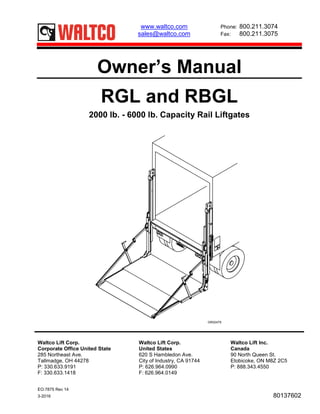
Om waltco rgl_rbgl-series_owners_manual_en-us_160225-w_original_85078
1. EO:7875 Rev 14
3-2016 80137602
Owner’s Manual
RGL and RBGL
2000 lb. - 6000 lb. Capacity Rail Liftgates
GR02479
Waltco Lift Corp. Waltco Lift Corp. Waltco Lift Inc.
Corporate Office United State United States Canada
285 Northeast Ave. 620 S Hambledon Ave. 90 North Queen St.
Tallmadge, OH 44278 City of Industry, CA 91744 Etobicoke, ON M8Z 2C5
P: 330.633.9191 P: 626.964.0990 P: 888.343.4550
F: 330.633.1418 F: 626.964.0149
www.waltco.com Phone: 800.211.3074
sales@waltco.com Fax: 800.211.3075
2. Table of Contents
Introduction .....................................................................................................................3
Safety Information...........................................................................................................4
Warranty .........................................................................................................................6
Liftgate Terminology .......................................................................................................7
RGL Operation Instructions ............................................................................................10
RBGL Operation Instructions ..........................................................................................16
Preventive Maintenance .................................................................................................18
Placement of Decals.......................................................................................................24
Lubrication Instructions...................................................................................................26
Platform Brake ................................................................................................................27
Cable Replacement ........................................................................................................28
Schematics .................................................................................................................... 30
How to Order Parts ........................................................................................................ 35
Improper operation and maintenance of this liftgate could result in severe
personal injury or death.
Read and understand the contents of this manual and all warning and operation
decals before operating and/or performing maintenance on this liftgate.
Page 2
3. INTRODUCTION
If anyone observes improper installation, improper operation, or damage, they should immediately
contact a qualified person for assistance and correction. We strongly urge anyone that has any
questions or doubts as to the installation, condition, use, operation, maintenance or repair of the liftgate
to contact us at Waltco where we have qualified personnel that will be happy to assist you. Telephone
numbers and addresses of these locations are listed in the Owner’s Manual and Installation
Instructions.
INSTALLATION
Waltco liftgates should only be installed by those with sufficient basic skills to understand the
installation and operation of the liftgate, along with the equipment on which the liftgate is being
installed. Waltco’s installation instructions are not intended to give rationale for all the instructions that
are given; however, it is the intent of these instructions to give the installer both the operations and
what we believe to be the most desirable sequence of implementing these operations. These
instructions can in no way expand into an area where they will replace a qualified person, or clear
thinking and a basic knowledge that must be possessed by the installer.
It has been our experience that a knowledgeable journeyman following these instructions and
observing the operation of the liftgate will have a sufficient comprehension of the liftgate to enable this
person to troubleshoot and correct all normal problems that may be encountered.
Failure to follow the installation instructions, adjustments and mounting dimensions may result in
improper and unsafe operation of the liftgate. Unauthorized alterations of the liftgate can cause an
undesirable and dangerous condition.
OWNER’S MANUAL
The Waltco Owner’s Manual is intended to act as a guide for operation and routine maintenance but
is no way intended to encourage usage or repair of the liftgate by those who are not qualified to do so.
The contents of the owner’s manual include, but are not limited to general operation instructions,
routine lubrication, parts lists, and an outline of things that should be checked but may not be obvious
to those not technically qualified. This manual assumes the liftgate is properly installed, undamaged
and operates correctly. Improper installation, improper operation, or damage should be immediately
corrected by a qualified person.
INSPECTION
As part of the regular inspection of a liftgate and after damage or suspicion of an overload, inspect
for wear or structural damage and make necessary repairs or replacements. Check all structural
components and their attachment to the liftgate for cracked welds, loose fasteners, wear and part
deformation. Check cylinder and hose for leaks. Inspections and repairs should be made by a qualified
mechanic.
REPLACEMENT PARTS
Use only Waltco original equipment replacement parts. Components of other liftgate manufacturers
may outwardly appear to be the same but are not interchangeable with Waltco products. Waltco
components are specifically designed for safety requirements, reliability and compatibility with our
products. Refer to your Waltco parts manual when ordering parts. NOTE: When ordering, give model
and serial number of liftgate.
DECALS
It is important that every vehicle that has a WALTCO Liftgate have legible DECALS clearly posted on
the vehicle and an OWNER’S MANUAL in the vehicle at all times as a guide for proper operation and
maintenance.
Additional DECALS and OWNER’S MANUALS can be obtained from WALTCO TRUCK
EQUIPMENT COMPANY 80101388 Rev 02 EO 6156
Page 3
4. Chapter 1 Safety Information
80101253 Rev 04 EO 6309JJ
WARNING
Read, understand, and follow all of the warning listed below.
Failure to follow these warning could result in severe personal injury or death.
• Read and understand the Owner’s Manual, all decals and warning on liftgate before operating liftgate.
• Do not operate liftgate without a thorough knowledge and understanding of the operation of the liftgate.
• Liftgate hazards can result in crushing or falling.
• This liftgate is designed for loading and unloading of cargo. If personnel are required to ride liftgate, observe
and familiarize yourself with the liftgate operation, decals and manuals. Ensure stable footing at all times.
• Do not ride liftgate with unstable loads.
• Wheeled loads must be properly retained from rolling.
• Tall, high center of gravity loads must be retained from falling over.
• Never overload liftgate:
Load platform as close to the vehicle, and towards the middle of the platform as possible. Refer to owner’s
manual and capacity decal of liftgate for maximum load and load placement.
• Keep hands and feet clear of all potential pinch points.
• Never use liftgate if it makes any unusual noise, has unusual vibration, raises or lowers unevenly, or fails to
operate smoothly.
• Never use liftgate if it shows any signs of structural damage such as cracked welds, bent or distorted
members.
• Do not attempt any repairs unless you are qualified to do so. Care should be taken when work is performed
on a disabled liftgate located near moving traffic. When possible the vehicle should be moved away from
traffic areas for repair. Precautionary measures should be taken to ensure personal safety including those
recommended in Federal Motor Vehicle Safety Standards 571.125.
• When welding to liftgate, or liftgate components, take all necessary safety precautions, including using
respiratory protection and other pertinent personal protective gear when welding harmful materials.
• All protective covers, guards, and safety devices must be in place and access doors closed before operating
liftgate.
• Do not allow anyone to stand in, or near area, in which Platform will open and close before opening or closing
Platform.
• Do not allow anyone to stand near the Platform where a falling load could land on them.
• Platform is always to be properly stored and secured for transit. See the Owner’s Manual for details.
• Take care to retain cargo during transit for liftgate Platforms which function as the tailgate or door of the cargo
area. Small objects can fall through the space between the vehicle and the folded Platform.
• A Lock-Out device or Shut-Off Switch should always be used to prevent unauthorized use of liftgate.
• For liftgates with Runners, never use liftgate if Runners do not travel freely and smoothly.
• For liftgates with Roller Lifting Chain, the Chain should be replaced every (5) five years or 15,000 cycles,
whichever comes first. Replace only with Waltco approved Roller Chain.
• Never transfer loads which exceed lifting capacity on or over any part of the Platform unless the liftgate is
equipped with a special reinforced Platform and Platform Support Bars for use when the Platform is used as
loading ramp (dock board). Refer to the “Using Platform as a loading ramp” Chapter in the Operation
Instructions of the BZ/RZ series Owner’s Manual.
• For liftgates equipped with Trailer Hitches, never exceed the rated capacity of the hitch. Do not exceed the
vehicle’s weight rating. Refer to the vehicle’s Owner’s Manual.
• Vehicle must comply with all state and federal standards.
• Follow the “Maintenance Guide” chapter in the Owner’s Manual.
Page 4
5. Chapter 1 Safety Information
80101253 Rev 04 EO 6309JJ
Liftgates with Tilt Function
• Proper use of the Control Switches is of extreme importance.
• Improper use of Tilt Switch could cause load to fall from the Platform or damage the liftgate.
• Platform should be in a generally horizontal position when raising or lowering with a load.
• In any tilt position, the Platform may vary from level while raising or lowering the Platform.
Liftgates equipped with spring operated Cam Closer
• Replace Cam Release Spring every five (5) years or 15,000 cycles, whichever comes first.
RGL-Series Liftgates
• Make certain Platform Brake mechanisms are operating properly.
• The Runners are always to remain powered up against the Upstops Pins when in transit.
• Inspect Cables every three (3) months or 750 cycles, whichever comes first. Cables must be replaced if they
show signs of wear, distortion, kinking or if any broken wires are visible
• Replace cables every five (5) years or 10,000 cycles, whichever comes first.
This is the safety alert symbol. This manual uses this symbol to alert you to potential personal injury
hazards.
Obey all safety messages that follow this symbol to avoid personal injury or death.
SIGNAL WORDS
WARNING
Indicates a potentially hazardous situation, which if not
avoided, could result in death or serious injury.
Black letters on an orange background
CAUTION
Indicates a potentially hazardous situation, which if not
avoided, may result in minor or moderate injury. May
also be used to alert against unsafe practices.
Black letters on a yellow background.
NOTICE
Indicates a potentially hazardous situation, which if not
avoided, may result in property damage. NOTICE
WARNING
CAUTION
Page 5
6. EO:7714 Rev 01
5-2015 80101667
WALTCO warrants its products free of defects in materials and workmanship.
WALTCO will replace components found defective during the warranty period. Labor will be
reimbursed according to our flat rate labor schedule at the prevailing shop rate.
Contact our Sales or Warranty departments for the warranty period of your model or for
information regarding our flat rate labor schedule.
WALTCO Warranty Claim Procedure
For consideration, all claims must be received within 30 days of repair and include the following
information:
• Liftgate Serial Number
• Description of problem and corrective actions
• Itemization of the labor charge to include the number of hours and labor rate
Replacement warranty parts can be obtained by contacting Waltco’s Parts Department.
Parts must be returned for inspection when requested.
Exclusions:
Waltco’s warranty does not include reimbursement for service calls, vehicle rental, towing, travel
time, fabrication of parts available from WALTCO, damage from misuse or abuse, negligence,
accidents, alteration, loss of income or overtime expense, oil, or normal wear.
Diagnosis and troubleshooting time are included in the flat rate labor times.
Warranty and technical information is available from WALTCO’s toll free customer service lines
from 8:00 a.m. to 5:00 p.m. EST.
Waltco Lift Corp
285 Northeast Ave, Box 354, Tallmadge, OH 44278
1-800-211-3074, 330-633-9191
Please visit our websites: http://www.waltco.com or http://www.hiab.com
We're behind you all the way!
Page 6
8. Chapter 2 Liftgate Terminology
13. Curb Side Rail
14. Control Switches
15. Safety Chain Assembly
16. Upstop Pin
17. Pulley Assembly
18. Pulley Guard Assembly
19. Brake Assembly
20. Upper Roller / Tandem Assembly
21. Drivers Side Rail
22. H-Frame Hose Guide
23. Lift Cylinder
24. Flow Control Valve
25. Crossbeam Access Cover
26. Hydraulic Hose
27. Runner Hose Guide
28. Torsion Bar Anchor
29. Slide Bearing
30. Curb Side Runner Assembly
31. Closure Cylinder
32. Chain Clip
33. Deck Assembly
34. Torsion Bar
35. Deck Extension Assembly
36. Drivers Side Runner Assembly
37. Upper Link Assembly
38. Connecting Bar Assembly
39. Lower Link Assembly
40. Curb Side Cable Assembly (Fixed)
41. Pulley Assembly
42. Drivers Side Cable Assembly (Adjustable)
43. Shoe Assembly
44. Specification Tag
GR02278
Page 8
9. Chapter 2 Liftgate Terminology
Explanation of Specification Tag
Model Name Description Capacity
RBGL30 Rail Lift, Bottle Gas 3000 lbs.
RBGL40 Rail Lift, Bottle Gas 4000 lbs.
RGL20 Rail Lift (96" WIDE) 2000 lbs.
RGL30 Rail Lift (96" WIDE) 3000 lbs.
RGL40 Rail Lift (96" WIDE) 4000 lbs.
RGL50 Rail Lift (96" WIDE) 5000 lbs.
RGL60 Rail Lift (96" WIDE) 6000 lbs.
RGL20 Rail Lift (102" WIDE) 2000 lbs.
RGL30 Rail Lift (102" WIDE) 3000 lbs.
RGL40 Rail Lift (102" WIDE) 4000 lbs.
RGL50 Rail Lift (102" WIDE) 5000 lbs.
RGL60 Rail Lift (102" WIDE) 6000 lbs.
GR00241
GR02279
Specification
Tag
NOTE: Tag located on
Curb Side Rail above
switches.
10. Chapter 3 Operation Instructions
OPERATION INSTRUCTIONS
Read and understand these instructions,
all warning and operation decals, and this
manual before operating this liftgate.
Platform and Runners are always to be powered up
against Upstop Pins when in transit.
Both safety chains must be used when liftgate is not
in use. A padlock may be used to prevent
unauthorized use of liftgate.
Never remove Safety Chains from Platform if chains
are in tension. Apply up power and closing power as
required to release tension on the chains.
When in transit Platform must be in stored position
with Safety Chains hooked securely.
Do not allow anyone to stand in, or near area, in
which Platform will open and close before opening
or closing Platform.
Do not allow anyone to stand near the Platform
where a falling load could land on them.
Platform Side Bar Linkage areas must be kept clear
for Platform opening and closing.
Certain conditions may cause Platform Brake(s) to
engage even if cable has not broken. In this case,
raise Platform first then lower Platform.
Make sure all protective covers and guards are properly
in place at all times.
DO NOT operate liftgate unless Pulley
Guards and Access Cover are installed and
secured.
GR02479
Access Cover
Pulley
Guards (2)
Safety Chain
Inside Control
Switch
Primary
Controls
Page 10
11. Chapter 3 Operation Instructions
LOADING OF PLATFORM
Load and unload from rear of platform and not side of
platform. Never remove side linkage to load or unload
platform.
Always load as close to center of platform and as close
to truck sill as possible.
Never operate lift trucks on or over any part of platform.
This unit is intended for loading and unloaded of cargo
only. Do not use for anything but its intended use.
TO RAISE AND LOWER PLATFORM IN DOCK
LOADING POSITION
Unhook Safety Chains from Platform
Press DOWN to lower Platform
Press UP Switch to raise Platform
TO OPEN PLATFORM TO LOADING POSITION
Unhook Safety Chains from Platform
Push the DOWN toggle switch and the OPEN toggle
switch simultaneously to power open the platform
TO RAISE/LOWER PLATFORM IN LOADING POSITION
Press UP Switch to raise Platform
Press DOWN Switch to lower Platform
12. Chapter 3 Operation Instructions
TO CLOSE PLATFORM TO TRANSIT POSITION
Press UP Switch to raise Platform at least 12” from ground
Push the UP toggle switch and the CLOSE toggle switch
simultaneously to power close the platform
Press UP Switch to raise folded Platform
Hook both Latch Chains to Platform
PROPER HOOKING OF SAFETY CHAIN
Properly hook latch chain as shown.
The safety chains provided with your
liftgate are an important safety device and
should always be in place when liftgate is
not in use.
To prevent unauthorized persons from
using liftgate, a padlock may be used in
place of “S” Hook.
Always use chains on both sides of liftgate
when not in use. GR02474
PROPER USE OF FOLDING RAMP
NOTE:
Folding ramps to be folded
and latched in place when
liftgate is closed in the transit
position.
GR02483
RAIS
LOWE
OPE
CLOS
Correct hooking
of “S” Hook
Incorrect hooking
of “S” Hook
Pad Lock
Page 12
13. Chapter 3 Operation Instructions
FOLDING RAMP OPERATION INSTRUCTIONS
Unlatch ramp and unfold to loading position.
Use cables for retention ramp application.
Assure ramp is latched when in transit position.
GR01553
CART STOP OPERATION INSTRUCTIONS
Push lever away from platform to release stop bar.
Rotate stop bar to lock in vertical position.
Rotate brace to engage stop bar.
GR01552
Ramp Latch
Stop Bar
Lever Lock
Lever
Stop Bar
Brace
Page 13
14. Chapter 3 Operation Instructions
DUAL PUMP OPERATION INSTRUCTIONS
The purpose of an optional Dual Pump unit is to provide
a backup in the event of a malfunction of the Primary
Pump or the switches on the column of the liftgate.
The Auxiliary Pump is NOT INTENDED FOR NORMAL
OPERATION of the liftgate. Liftgate must be repaired as
soon as possible after a malfunction of the Primary
Pump unit occurs.
The Auxiliary Pump unit is operated with the Hand Held
Remote Control located in the Hydraulic Enclosure.
TO OPERATE THE PRIMARY PUMP:
Move toggle switch on the pump to the “Primary
Position”.
Operate liftgate with controls on columns as usual.
TO OPERATE THE AUXILIARY PUMP:
Move toggle switch on the pump to the “Auxiliary
Position”.
Operate liftgate with Hand Held Remote Control.
GR02135
AUXILIARY HAND HELD REMOTE CONTROL:
Auxiliary Pump Hand held remote operates in the same
manner as the outside Main Control Switches.
Use the center switch in conjunction with the Raise or
Lower switches to close or open platform.
GR02043
Toggle Switch
Raise Button
Open / Close
Button
Lower Button
Page 14
15. Chapter 3 Operation Instructions
OPERATION OF MANUAL OVERRIDE VALVES TO
LOWER AND UNFOLD PLATFORM IN EVENT PUMP
ISN’T FUNCTIONING:
Do not allow anyone to stand in, or near
area, in which Platform will open and/or
lower.
Use valve (A) to open platform. Then valve (B)
to lower platform to ground.
GR01987
HAND PUMP OPERATION INSTRUCTIONS:
Hand Pump option is to provide a backup in the event of
a malfunction of the batteries, pump unit or controls.
The Hand Pump is NOT INTENDED FOR NORMAL
OPERATION of the liftgate. Liftgate must be repaired as
soon as possible after a malfunction occurs.
Make certain Manual Override Valves (A & B) are
closed.
Raise platform to bed level with Hand Pump.
Make certain platform surface is clear of all objects.
Continue to pump until platform is closed.
Do not over pressurize hydraulic system.
Once platform is closed, stop pumping.
Install Safety Chains.
GR02484
A
B
BA
Page 15
16. Chapter 4 RBGL Operation Instructions
RBGL SERIES OPERATION INSTRUCTIONS
The RBGL is specifically designed for handling tall loads
such as cylinder gas bottles.
Securing loads can be accomplished by using the
chains.
After placing a load in position, fasten chain snugly
around load to Chain Hook on Runner.
After use, chains are hooked to Guard Rail and ramp is
folded onto the platform skin for transit.
GR02485 - 86
FOLDING RAMP USED AS CART STOP
Folding Ramp may be used as a retaining device to
prevent carts and similar devices from rolling off
platform.
GR02487
Latch
Chain Chain Hook
Chain in transit position
Folding Ramp
Page 16
17. Chapter 4 RBGL Operation Instructions
RBGL WITH FIXED RAILS IN DOCK LOADING
POSITION.
When dock loading, ramp is to be folded down onto
platform skin before raising platform to closed position.
GR02488
RBGL WITH FOLD DOWN RAILS (optional)
Fold Down Rails can be folded down out of the way to
increase available opening width when dock loading.
GR02489
Page 17
18. Chapter 5 Preventive Maintenance
Waltco recommends that the RGL-Series liftgate be inspected at recommended intervals listed below to help
assure proper function and operation of the liftgate.
Note: Photocopy the following PM Checklist to help keep track of periodic maintenance on the liftgate. Keep
completed form with maintenance records.
For more detailed instructions on the following checklist items, refer to the appropriate sections in this Owner’s
Manual.
DO NOT CONTINUE TO USE LIFTGATE IF ANY POINTS OF INSPECTION LISTED BELOW,
MAY CAUSE YOU TO THINK THE LIFTGATE IS UNSAFE. REPAIR IMMEDIATELY.
If liftgate is found to be in need of repair or adjustment not covered in this manual, contact
your nearest Waltco Distributor.
WALTCO RGL/RBGL-SERIES LIFTGATE
PREVENTIVE MAINTENANCE CHECKLIST
PM Interval: As listed below Date: ______________ Vehicle No.__________
Mechanic:_________________ Liftgate S/N:____________ Model:______________
Check appropriate box below for each step:
Weekly PM Procedures
1 OK Repair Required Corrected Check platform brake (weekly procedures).
Monthly PM Procedures
2 OK Repair Required Corrected Check liftgate operates freely and smoothly throughout entire operation.
3 OK Repair Required Corrected Check platform brake (monthly procedures).
4 OK Repair Required Corrected Check for apparent damage to the lifting structure, such as bent or
distorted members or cracked welds.
5 OK Repair Required Corrected Check that all pins, bolts and fasteners are tight and secure.
6 OK Repair Required Corrected Check for worn or damaged bearings, pulleys, rollers, all pivot points.
7 OK Repair Required Corrected Check safety chains and hooks.
8 OK Repair Required Corrected Check that controls operate properly.
9 OK Repair Required Corrected Check operating speeds.
10 OK Repair Required Corrected Check for hydraulic leaks in hydraulic cylinder(s), hoses, fittings, and
valves.
11 OK Repair Required Corrected Check all battery cables and connections (both positive and ground
cables) to be sure they are tight and free of corrosion.
12 OK Repair Required Corrected Check oil level in reservoir.
13 OK Repair Required Corrected Check that all decals are in place and legible.
14 OK Repair Required Corrected Lubricate the liftgate per the “Lubrication Instructions”.
3 Month PM Procedures (Includes steps 2-14 above)
15 OK Repair Required Corrected Check entire length of both lifting cables. Replace cables every 5 years
or 10,000 cycles whichever comes first.
Semi Annual PM Procedures (Includes steps 2-15 above)
16 OK Repair Required Corrected Check motor brushes, clean motor housing and change oil.
Page 18
19. Chapter 5 Preventive Maintenance
WEEKLY INSPECTION
Platform Brake
Lower opened platform to within a few inches of the
ground. Place a 4 X 4 or similar block under the
Platform Side Tube at main Platform Pivot.
Lower opposite side of platform to the ground so that
platform is resting at an angle.
While raising platform with raise switch, listen for a
“click” near top of Runner. If no “click” is heard, try
again. If still no “click”, the “Monthly Inspection” must
be conducted.
Repeat above test for opposite Runner.
Do not use liftgate if Platform Brake is not
functioning properly. Have liftgate
serviced immediately.
GR02490
MONTHLY INSPECTION
1. Check that liftgate operates freely and smoothly
throughout its entire operating cycle and there are
no unusual noises.
2. Check that platform is level when raised to bed
height.
3. Perform the following steps to test Platform Brake
mechanism:
• Lower open platform to within a few inches of
ground. Place a suitable hydraulic or scissor
type jack under Platform Side Tube at main
Platform Hinge.
• Jack Platform and Runner up approximately 3”
relative to Rail.
• Lower jack. If Platform and Runner remain in the
raised position then Platform Brake is
operational.
• Push Raise Switch to raise entire platform
several inches above test position and Platform
Brake should disengage.
• Lower platform and repeat for
the opposite side Platform Brake.
Do not use liftgate if Platform Brake is not
functioning properly. Have liftgate
serviced immediately.
GR02491
Platform Side Tube
Main Pivot
Hinge
Runner
Main Platform
Hinge
Platform Side Tube
Jack
Runner
Page 19
20. Chapter 5 Preventive Maintenance
4. Inspect entire length of both Cables. Replace if
necessary.
Entire length of both Cables must be
inspected a minimum of every three (3)
months or 750 cycles, whichever comes
first.
Cables must be replaced if they show any signs of wear,
kinking, corrosion, distortion, or if any broken cable
wires are visable.
Cables must be replaced every five (5)
years or 10,000 cycles, whichever comes
first.
Any time Cables are replaced, all Pulley
Bolts and lock washers must also be
replaced. Waltco provides kits for
Cable/Pulley Bolt replacement.
During Cable and Pulley Bolt replacement, also inspect
the Pulleys and Pulley Bearings. If any components are
worn or otherwise deteriorated they must be replaced. If
bearings do not rotate freely, they are to be replaced.
GR02492
5. Check for apparent damage to liftgate, such as bent
or distorted members and/or any cracked welds,
which may have resulted from overloading or abuse.
6. Check for any excessive wear in the Cable Pulleys,
Bearings and Rollers, Platform Linkage and Pins,
7. Closer Mechanism, Pulley Bolts, and all pivot points.
8. Check that all nuts and bolts are in place and
properly tightened.
9. Check that all Pivot and Stop Pins are in place and
retained by their proper fasteners.
10. Check that all control switches operate properly.
11. Check the Platform opening and closing speed. The
Platform must open and close smoothly and at a
safe and reasonable rate of speed subject to the
environment in which it will be operated.
12. On platforms with Side Linkage, inspect the Torsion
Bars with the platform in loading position at bed
level. If any Torsion Bars are broken they must be
replaced.
DO NOT get under Platform to inspect
Torsion Bars.
13. On platforms without side linkage, inspect Torsion
Springs visually with Platform in stored position. If
any Torsion Springs are broken they must be
replaced.
GR02497
Torsion
Bars
Torsion
Springs
Fixed
Cable
Pulley
Assembly
Adjustable
Cable
Pulley
Guard
Pulley
Assembly
Page 20
21. Chapter 5 Preventive Maintenance
14. Inspect entire length of Closer Cylinder Hose for
signs
15. of wear, abrasion, or leakage. Hose should flex
easily throughout operating cycle with no binding.
16. Check Hose Guides for bends or damage.
17. Check for oil leaks in hydraulic Lift Cylinder,
hydraulic Closer Cylinder, and all hydraulic hoses
and fittings. Replace any hose that show any sign of
excessive abrasion of the covering. Tighten or
replace any hydraulic component as required to stop
oil leakage.
18. Check level of oil in liftgate hydraulic Reservoir with
the Platform at ground level. The oil should be within
1/2" of top of Reservoir.
19. Lubricate the liftgate by following the “Lubrication
Instructions” chapter in this manual.
20. Check the electrolyte level of vehicle battery. Fill as
required per manufacturer recommendation.
21. Examine all Warning, Capacity, and Operation
decals.
If any decals are illegible and need to be
replaced, decals can be obtained free of
charge from Waltco.
If liftgate is found to be in need of repair or
adjustment not covered in this manual,
contact your nearest Waltco distributor.
GR02493
CHECK BATTERIES
Check electrolyte level of batteries.
Check that all wiring and battery cable connections are
tight and free of corrosion.
All electrical connections are to be coated with dielectric
grease.
GR01471B
CHECK OIL LEVEL
Lower platform to ground in open position.
Fill hydraulic reservoir to within 1/2" of top of reservoir.
GR02135
H-Frame
Hose Guide
Closer
Hose
Curb Side Runner
Hose Guide
Filler Plug
Page 21
22. Chapter 5 Preventive Maintenance
Recommended Fluids Fill reservoir
Temperature Range Acceptable Fluids • Fill with recommended fluid or equivalent.
0° to 120° F Waltco Biodegradable
Liftlube
TM
part #85803860
• Fill the reservoir to within 1/2” from the top.
• Fluids are available from the Waltco parts
Shell Tellus S2 V 32 Dept. 1-800-411-5685 www.waltco.com
Chevron Rando HDZ 32
-20° to 90° F Waltco Biodegradable
LiftLube Arctic part
#85803866
NOTE:
Do not use the following fluids:
Waltco All Season Hyd Oil
Part 85803867
Shell Tellus S2 V 15
Mobil DTE 10 Excell 15
Brake Fluid
Power steering fluid
Automatic Transmission Fluid (ATF)
A good quality SAE 10W motor oil may also be used in
temperatures above 32° F. Rev 06
SEMI ANNUAL INSPECTION
1. Perform procedures outlined in “Monthly Inspection”
2. Inspect pump unit motor:
• Disconnect battery cables.
• Remove motor end cover.
• Examine armature brushes for wear. Motor
should be replaced if brushes are less than 1/8"
long.
• Clean out all residue from inside motor housing
• Apply several drops of light weight machine oil
to armature shaft bearing in motor end cover
and reassemble motor end cover.
If oil is dirty, drain oil from hydraulic system and
flush entire system. To replace Hydraulic Fluid:
• Open platform and lower to ground.
• Drain oil from hydraulic system using drain port
located on bottom of reservoir and flush entire
system.
• Fill reservoir to within 1/2” of top of reservoir
GR02135
Motor
Reservoir
Page 22
23. Chapter 5 Preventive Maintenance
PLATFORM ADJUSTMENT
If platform is not level with floor of vehicle check that
both up-stop pins are properly secured in place.
If not, up-stop pins must be re-installed properly.
If platform is still not level proceed to next step.
GR02494
Unfold and raise platform to bed level and measure
how uneven platform is in relationship to vehicle floor.
This will be your “X” dimension.
Lower platform to ground. Remove access cover from
crossbeam box.
GR02495
Loosen locknut. If curb side of platform is lower than
street side, adjust cable to the right by turning the
adjusting nut counterclockwise from cable end. If street
side of platform is lower than curb side, adjust cable to
the left by tuning the adjusting nut clockwise from cable
end. Adjust cable the same distance as “X” as
measured above. Tighten locknut.
Make certain adjusting nut is fully threaded
on cable end and tightened.
Reinstall access cover.
GR02496
WRONG
RIGHT
Top of
Platform
“X”
Vehicle Bed
Lock Washer
Cable End not to be
below surface of nut
Up-stop Pin
Street
Side
Curb
Side
Adjustable Cable End
Page 23
24. Chapter 6 Placement of Decals
All decals must be in place and legible or all warranties are void.
All decals must be in place and legible or all warranties are void.
ITEM DECAL QTY PART NO. LOCATION
1
Safety Instructions 1 80100850
Locate in a conspicuous place near controls.
If your liftgate is equipped with dual controls, an
additional Safety Instruction decal (80100850) is
to be placed in a conspicuous place near the
second set of the controls.
Operation 1 80101669
2000 lb Capacity Decal
1
80100253
3000 lb Capacity Decal 80100257
4000 lb Capacity Decal 80100260
5000 lb Capacity Decal 80100263
6000 lb Capacity Decal 80100265
Circuit Breaker Decal 1 80100828
Hazard Decal 1 80101370
Caution Stand Clear 1 75089296 Locate one in a conspicuous place near controls.
2 Caution Stand Clear 1 75089296 Locate near liftgate on street side of vehicle.
3 Caution Decal 2 75089282 Locate near top of each rail, not on pulley covers themselves,
so can be read when removing pulley covers.
4 Important Decal 6 75089280
Locate one each in a conspicuous place near upper and
lower pulley bolts, main cylinder bolts, shoe assembly bolts,
and upper and lower cylinder bolts.
5 Caution Decal 2 75089282 Locate one on shoe assembly and one on bottom of
crossbeam box, under cylinder.
6 Caution Stand Clear 2 75089296
Locate on back (bottom) side of platform or ramp so as
to be visible when liftgate is in stored position. Used on
liftgates equipped with single section platform or with
folding ramp.
7 Safety Chain Decal 2 80100527 Locate at base of both runners.
8 Important Decal 1 80100482
Locate on lower curb side linkage. Used on liftgates
equipped with a folding ramp.
9 Warning Decal 1 80100829
Locate next to circuit breaker. If more than one circuit
breaker is used; decal must be in both locations.
10
Selector Switch Decal,
Single Pump Only
1
80101371
Locate appropriate decal on pump unit selector switch
bracket.Selector Switch Decal,
Dual Pump Only
80101380
11
Dual Pump Decal
1
80101021
Locate decal inside hydraulic enclosure cover for all dual
pumps.
Hand Pump Decal 80101199
Locate decal inside hydraulic enclosure cover for liftgates
with Auxiliary Hand Pump Option.
12
Single Pump Decal
1
80101372
Locate decal inside hydraulic enclosure cover for all single
pumps.
Dual Pump Decal 80101373
Locate decal inside hydraulic enclosure cover for all dual
pumps.
13 Conspicuity Tape 1 82021067
Locate on back (bottom) side of platform or ramp so as
to be visible when liftgate is in stored position.
Page 24
25. Chapter 6 Placement of Decals
GR02475
To maximize decal adhesion to
surfaces:
• Surface must be dry and clean
• Firm pressure must be applied
to decal
• Minimum surface temperature
65º
Heat gun may be used to heat
surface
Page 25
26. Chapter 7 Lubrication Instructions
The liftgate should be lubricated every 120 days.
#1 – Grease with automotive type chassis grease with platform resting on ground.
#2 and #3– Oil with WD-40 or equivalent.
#1 Lubricate with chassis grease:
• Under shoe assembly
• Using a rag, lightly lubricate outside faces of
rails with light chassis grease if required for
smooth operation. Lubricate only areas where
bearings slide on rails.
Do not operate liftgate if any guards or
access covers are not in place and
properly secured.
#2 Lubricate with WD-40 or equivalent:
• Platform Linkage which includes Torsion Bar
Anchors, and Springs on one-piece platforms.
NOTE:
Take care not to nick or scratch exposed cylinder
shaft as this could cause cylinder leakage.
GR02476
#3 With Platform at bed level, use WD-40 or equivalent
to lubricate two areas of both Platform Brake
Mechanisms.
A. Spray inside Lifting Cable Yoke end where it
attaches to Runner Assembly.
B. Spray generously with a circular motion inside
lubrication holes on both sides of each rail.
Use only WD-40 or equivalent light spray
lubricant to lubricate Platform Brakes. DO
NOT use grease
or heavy oil that may tend to build up and
become gummy.
NOTE:
Cables, Roller Bearings, and Pulley Bearings do not
require lubrication. While cables do not require
lubrication, if cables have ever been lubricated it is
recommend they continue to be lubricated.
GR02477
A
B
Cable Yoke
End
Rail
Runner
Spray in
lubrication holes
on both sides of
each rail
Pulley covers not shown
for clarity. Pulley covers
MUST be in place at all
times during operation
of liftgate.
Page 26
27. Chapter 8 Platform Brake
PLATFORM BRAKE
This liftgate is equipped with a platform brake system,
designed to prevent the platform from falling in the event
a lifting cable breaks. These platform brakes must never
be used as a substitute for timely inspection and
replacement of cables.
Certain conditions and/or circumstances
may prevent platform brakes from
functioning consistently. These platform
brakes are not intended to and must not
take the place of proper cable
maintenance. Lifting cables must always
be inspected and replaced as described in
this owner’s manual.
In the event a cable does break, do not
move vehicle with a load on platform.
Platform must be unloaded and secured for
transit before vehicle is moved.
GR02498
DECSRIPTION AND FUNCTION OF PLATFORM
BRAKE
The platform brake system consists of two independent
brake mechanisms located at the upper portion of the
runner assemblies (inside the rails).
Each platform brake assembly has a toothed cam. This
cam is joined by a spring and connector plate to lifting
cable. If cable is pulled taut, the cam pivots away from
the rail and runner is free to travel up and down the rail.
Should a cable break, spring tension (lower spring)
pivots the cam so teeth contact the inside of rail,
causing runner to lock at that position.
Under certain conditions, one or both platform brakes
may engage (even if a cable has not broken), thus not
allowing platform to lower or allowing only one side to
lower.
If this happens and a cable has not broken, platform
brake(s) can be disengaged by raising platform to bed
level and slightly powering up against upstop pins.
NOTE:
Never allow platform to lower unevenly.
GR02499
Toothed
Cam
Cam Pivot Pin
Lifting Cable
To Connector
Plate and Cable
Lower Spring
Rail
Locked
(braked)
position
Runner
Connector
Plate
Springs
Normal
operating
position
Cam Pivot Pin
Page 27
28. Chapter 9 Cable Replacement
CABLE REPLACEMENT
Do not move vehicle with a load on
platform.
Platform must be unloaded and secured for
transit before vehicle is moved.
It is very important that both cables be
replaced at the same time.
Any time cables are replaced, remove
platform brake assembly for thorough
cleaning and inspection. In addition, all
pulley bolts and lock washers must also be
replaced.
Follow these procedures for replacing cables; if you are
performing a periodic replacement of cables then skip to
step 3.
1. If a cable is broken, carefully unload platform. Use a
forklift to support runner (side with broken cable).
Only then remove upper bearing assembly mount
bolts from runner (with broken cable).
Be sure to use safety precautions to avoid
injuries.
GR02243
2. Lower platform slowly to ground by using one
person to push Lower Switch and another to lower
side of platform with forklift.
NOTE:
Be careful during this operation to prevent any
damage to liftgate.
3. Make certain platform is on ground. If bolts have not
been removed from upper bearing assembly do so
at this time.
4. Remove pulley cover guards, upstop pins and upper
pulleys from top of both rails.
5. Lift upper bearing/brake assemblies out of rails
by the cable.
Cable may have broken wires sticking out –
using leather gloves is recommended.
NOTE:
Bearing/Brake assembly should be pulled out by
the Cable. If unable to do so, insert a screwdriver
between Cable Anchor and Upper Bearing/Brake
Mount Plate. This will release Brake so Bearing
Assembly can be pulled out of Rail.
GR02244
Pulley Bolt
Nut
Pulley
Coiled
Pins
Upper Pulley
Cover Guard
Upper Bearing
Assembly
Remove these bolts
Runner
Position Fork
under Runner
Lock Washer
Flat Washer
Upstop Pin
Insert a screwdriver or
similar tool and wedge
cable end up to
disengage brake
Page 28
29. Chapter 9 Cable Replacement
6. Remove old cables from liftgate, making note of
how cables are routed. Install new cables.
NOTE:
Use proper cables. Cables used on liftgates with
Brakes must have 2-5/8” deep end slots as shown.
7. Platform brakes should be inspected cleaned and
lubricated at this time (see below).
8. Attach yoke end of new cable to brake
assemblies.
9. Use a screwdriver, if required, to lower
bearing/brake assembly down into rail
(see previous page).
NOTE:
Special care must be observed when attaching
Cable End to platform Brake Mechanism so use
proper parts as shown.
10. Reinstall upper pulleys, upstop pins and pulley
cover guards (ref previous page).
11. Line up holes in bearing/brake assembly with
mount holes in top of runner and install bolts, nuts
and lock washers.
12. Double check that all nuts, bolts, washers, and
coiled pins are in place and properly secured.
13. Adjust cables to level out platform per instructions
in this manual.
14. Test operation of each platform brake assembly
as outlined in the “Maintenance Guide” in this
manual.
GR02245
INSPECTION OF PLATFORM BRAKES
Examine platform brake assembly for loose pins, bent
or damaged parts, etc. Replace any damaged
components.
Make certain all parts including cam moves freely
without binding which may be caused by corrosion,
bent pins, etc.
Be certain springs are not corroded, bent or broken.
Replace if necessary.
Examine toothed cam for chipped, broken or dulled
teeth. Replace if signs of damage. Clean any grease,
dirt, etc. from teeth of cam.
Lubricate areas shown with “WD-40” or similar light
spray lubricant.
GR02500
3/8”-16 Locknut
1/2" X 1-1/4” w/3/8”-16
Socket Head Shoulder
Screw
2-5/8” Deep slot
1-1/4” Shoulder
Bearing / Brake
Assembly
Lifting Cable
Lower Spring
(smaller)
Toothed Cam
Upper Spring
(larger)
Cam Pivot Pin
(welded in place)
Lower Spring
Pin (welded
place)
Roller
Connector Plate
Cam Spring
Pin*
Page 29
35. 80101389 EO 5534A
Rev 02
How To Order Parts
Repairs should be made only by authorized mechanics using WALTCO
Replacement parts.
When ordering repair or replacement parts, please include all the
information asked for below. If this information is not available, a complete
written description or sketch of the required part will help WALTCO identify
and deliver the needed part to you.
________________________________________________________________
THE FOLLOWING INFORMATION MUST BE INCLUDED:
1. SERIAL NUMBER - [WALTCO liftgate serial numbers can be found on the
Specification Tag attached to the mount frame. (On older units the
Specification Tag is located on the side or bottom of the platform.)]
2. MODEL NUMBER - [Or capacity]
3. PLATFORM SIZE
________________________________________________________________
THEN INCLUDE THE FOLLOWING INFORMATION:
4. PART NUMBERS
5. DESCRIPTION
6. QUANTITY REQUIRED
________________________________________________________________
MAIL, E-MAIL OR PHONE YOUR REQUEST TO:
Waltco Truck Equipment Co.
285 Northeast Avenue
Tallmadge, OH 44278
1-800-411-5685
FAX: 1-800-411-5684
E-MAIL: parts@waltco.com
ALL PARTS ARE F.O.B. FROM THE SHIPPING FACTORY
________________________________________________________________
PLEASE NOTE:
To assure you of continuing and effective quality control, our warranty
policy permits replacement of hydraulic cylinders, valves and motor pump
units when their factory seals are intact. Parts under warranty will be
exchanged promptly after careful inspection of the returned assemblies.
Page 35
37. Every vehicle that has a WALTCO Liftgate must have legible
WARNING AND OPERATION DECALS clearly posted on the
vehicle and an OWNER’S MANUAL in the vehicle at all times as
a guide for proper operation and maintenance.
Additional WARNING DECALS, OPERATION DECALS and OWNER’S MANUALS can
be obtained from WALTCO TRUCK EQUIPMENT COMPANY.
____________________
NOTE:
When ordering, give model
and serial number of the liftgate.
____________________
Page 37
38. IMPORTANT
KEEP THIS OWNER’S MANUAL IN THE VEHICLE
WARNING
Improper operation and maintenance of this
liftgate could result in severe personal injury
or death.
Read and understand the contents of this
manual and all warning and operation decals
before operating and/or performing
maintenance on this liftgate.
For SAFETY information on this liftgate see
Chapter 1 of this manual
80101519 EO6156
Rev 01
Page 38