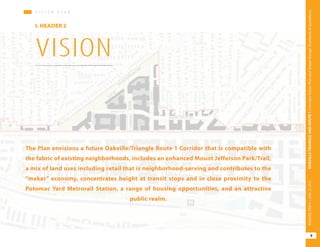
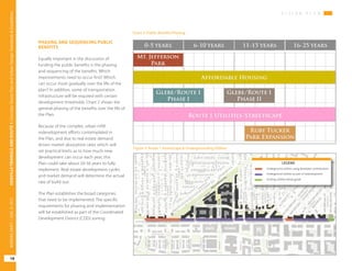
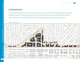
The vision plan for the Oakville Triangle/Route 1 Corridor area envisions a mixed-use, transit-oriented development with the following key elements:
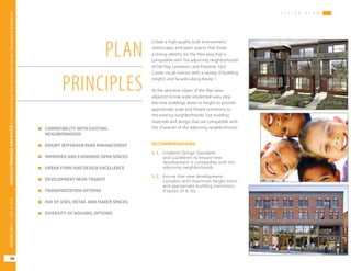
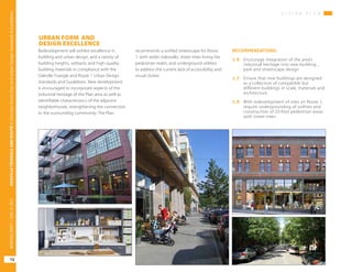
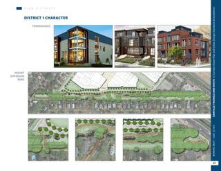
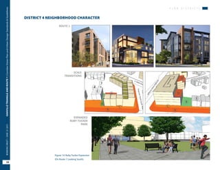
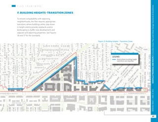
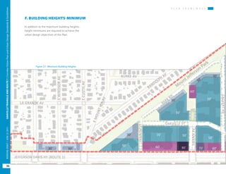
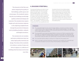
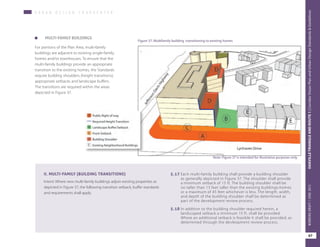
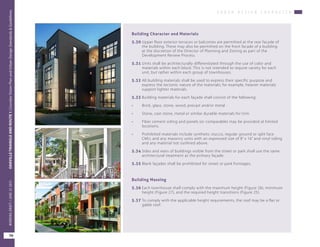
- Compatibility with existing neighborhoods through building height transitions and design standards.
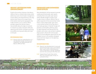
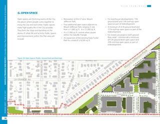
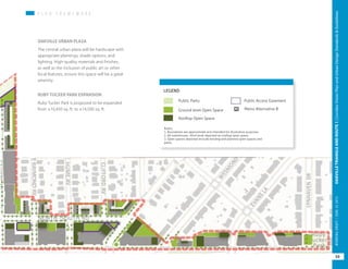
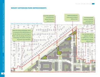
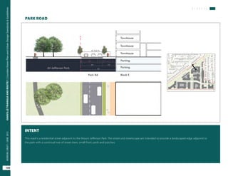
- Enhancement of Mount Jefferson Park and new open spaces.
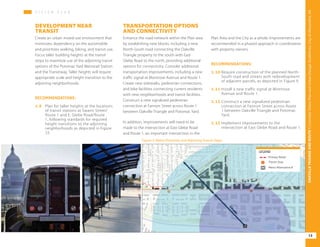
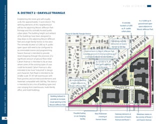
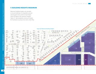
- Focusing taller buildings near transit stops to maximize transit access.
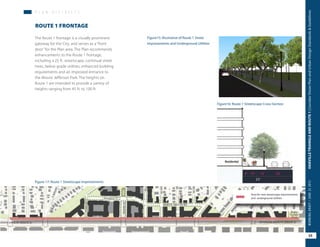
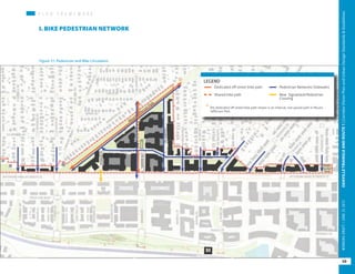
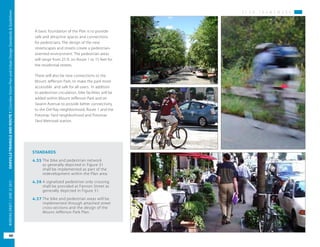
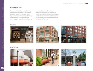
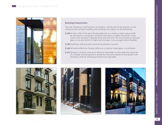
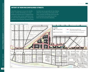
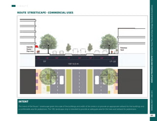
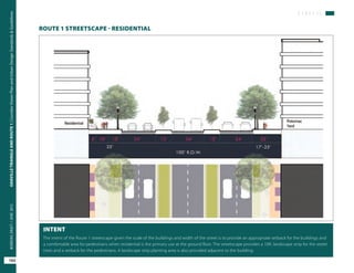
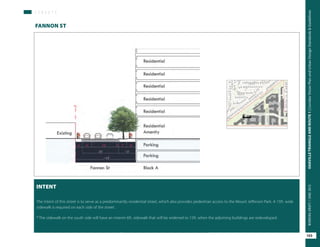
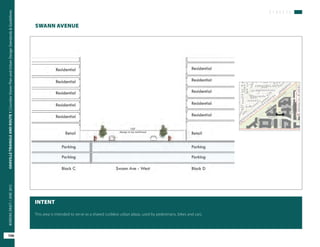
- Improving streetscapes, adding new streets, and enhancing transportation options and connectivity for walking, biking and transit.
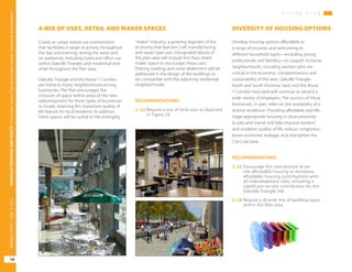
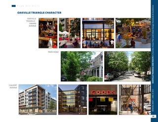
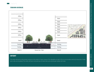
- Encouraging a mix of uses including retail, office, hotel and housing with a range of affordability levels.
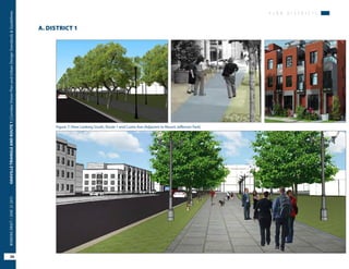
The plan provides recommendations to implement this vision through zoning, design standards, transportation