NOS NGS 92, network design, Classifications Standards and Specifications, OPUS Projects
1.
1
NGS Webinar
Design ofNetworks Using NOS NGS 92
Classifications, Standards, and Specifications for GNSS Geodetic Control Surveys
using OPUS Projects
April 21, 2025
Dave Zenk PE LS, Northern Plains Regional Advisor
Dan Martin, Northeast Regional Advisor
Lynda Bell, Alaska Regional Advisor
Design of Networks Using NOS NGS 92
April 21, 2025
2.
2
NGS Webinar
• Ourprevious webinar on April 13, 2023 introduced the public to: NOAA
Technical Memorandum NOS NGS 92 Classifications Standards and
Specifications for GNSS Geodetic Control Surveys using OPUS Projects
– Following NOS NGS 92 is required for surveys to become part of the NGS Integrated
Database.
• The NOS NGS 92 document received final approval on October 23, 2024
and is available for download from NGS Publications library website.
NOAA Technical Memorandum NOS NGS 92
https://geodesy.noaa.gov/library/pdfs/NOAA_TM_NOS_NGS_0092.pdf
• An updated set of slides is available from the NGS Presentations Library.
https://geodesy.noaa.gov/web/science_edu/presentations_library/
Design of Networks Using NOS NGS 92
April 21, 2025
3.
3
NGS Webinar
Today’s webinarwill:
– Review NOS NGS 92 Tables 1 through 10,
– Review a few Key Concepts,
– Show an example survey design that implements the
various NOS NGS 92 Standards and Specifications.
• But, today’s webinar will not:
– Process any data,
– Analyze results, nor
– Discuss the reportage of a project’s outcome.
Design of Networks Using NOS NGS 92
April 21, 2025
4.
4
Review of NOSNGS 92 Tables 1 through 10
Design of Networks Using NOS NGS 92
Tables are included here for convenience of reference.
Users should download and read the NOS NGS 92.
April 21, 2025
5.
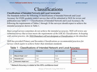
Classifications
April 21, 2025Design of Networks Using NOS NGS 92 5
Classifications of Intended Network and Local Accuracies
The Standards defines the following 3 Classifications of Intended Network and Local
Accuracy for GNSS geodetic control surveys that will be submitted to NGS for review and
publication (see Table 1 — Classifications of Intended Network and Local Accuracy). By
following the requirements of Tables 2 through 10 the surveyor should expect to achieve the
intended accuracies shown in Table 1.
Since actual surveys sometimes do not achieve the intended accuracies, NGS will review any
submitted survey that at least meets the requirements of the LOCAL Classification. In keeping
with current practice, the NGS Datasheet will not designate a Classification on the datasheet.
NGS has provided Primary and Secondary Classifications as recommended practices for
surveys which aspire to achieve better than minimum standards.
* Network Accuracy is stated at the 95% confidence level
Description PRIMARY SECONDARY LOCAL
1.1 Ellipsoid Height (cm) * 2 cm 3 cm 5 cm
1.2 Horizontal (cm) * 1 cm 1.5 cm 2.5 cm
1.3 Orthometric Height (cm) * 3 cm 4 cm 6 cm
Table 1 - Classifications of Intended Network and Local Accuracy
6.
6
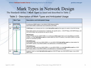
Mark Types inNetwork Design
Table 2 - Description of Mark Types and Anticipated Usage
The Standards define 3 Mark Types as listed and described in Table 2.
Mark Type Description and Anticipated Usage
2.1 NCN CORS A continuous GNSS station in the NOAA CORS Network (NCN).
Each NCN CORS is well-known and monitored by the NGS.
2.2 GVX Base A GVX base is an inclusive term for a mark that will be used as the origin of a vector in the GVX format.
Since GVX vectors can be derived by 3 methods, the specific terms — GVX PP Base, GVX NRTK Base, and
GVX SRTK Base may sometimes be used for clarity.
GVX PP base
A GVX PP base can be a NCN CORS, or a continuous GNSS station that is not in the NCN (a non-NCN
CORS), or a mark that will be used as a base station for GVX PP vectors. A non-NCN CORS is not well-
known or monitored by NGS.
GVX NRTK base
A GVX NRTK base can be an NCN CORS, or a non-NCN CORS that will be used as a base station for
GVX NRTK vectors. A non-NCN CORS is not well-known or monitored by NGS.
GVX SRTK base
A GVX SRTK base can be an NCN CORS, or a non-NCN CORS, or a mark that will be used as a GVX
SRTK base station. A non-NCN CORS is not well-known or monitored by NGS
2.3 Passive A passive mark is a mark that will not be used as a GVX PP base, as a GVX NRTK base, or as a GVX
SRTK base.
Design of Networks Using NOS NGS 92
April 21, 2025
7.
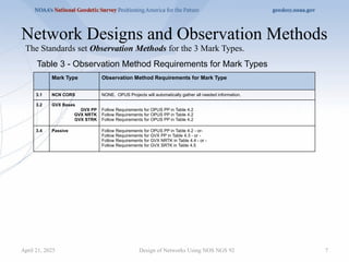
Network Designs andObservation Methods
Design of Networks Using NOS NGS 92 7
The Standards set Observation Methods for the 3 Mark Types.
Table 3 - Observation Method Requirements for Mark Types
Mark Type Observation Method Requirements for Mark Type
3.1 NCN CORS NONE. OPUS Projects will automatically gather all needed information.
3.2 GVX Bases
GVX PP
GVX NRTK
GVX STRK
Follow Requirements for OPUS PP in Table 4.2
Follow Requirements for OPUS PP in Table 4.2
Follow Requirements for OPUS PP in Table 4.2
3.4 Passive Follow Requirements for OPUS PP in Table 4.2 - or-
Follow Requirements for GVX PP in Table 4.3 - or -
Follow Requirements for GVX NRTK in Table 4.4 - or -
Follow Requirements for GVX SRTK in Table 4.5
April 21, 2025
8.
8
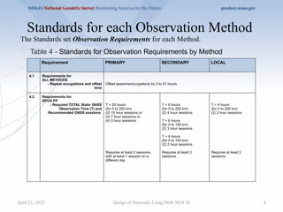
Standards for eachObservation Method
Design of Networks Using NOS NGS 92
Table 4 - Standards for Observation Requirements by Method
Requirement PRIMARY SECONDARY LOCAL
4.1 Requirements for
ALL METHODS
- Repeat occupations and offset
time
Offset sessions/occupations by 3 to 21 hours.
4.2 Requirements for
OPUS PP
- Required TOTAL Static GNSS
Observation Time (T) and
Recommended GNSS sessions
T = 20 hours
(for 0 to 200 km)
(2) 10 hour sessions or
(3) 7 hour sessions or
(4) 5 hour sessions
Requires at least 2 sessions,
with at least 1 session on a
different day
T = 8 hours
(for 0 to 200 km)
(2) 4 hour sessions
T = 6 hours
(for 0 to 150 km)
(2) 3 hour sessions
T = 4 hours
(for 0 to 100 km)
(2) 2 hour sessions
Requires at least 2
sessions.
T = 4 hours
(for 0 to 200 km)
(2) 2 hour sessions
Requires at least 2
sessions.
The Standards set Observation Requirements for each Method.
April 21, 2025
9.
9
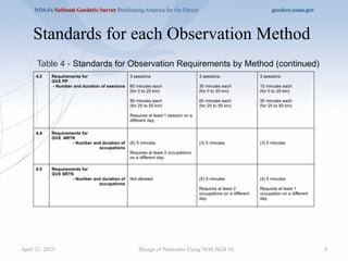
Standards for eachObservation Method
Design of Networks Using NOS NGS 92
4.3 Requirements for
GVX PP
- Number and duration of sessions
3 sessions
60 minutes each
(for 0 to 25 km)
90 minutes each
(for 25 to 50 km)
Requires at least 1 session on a
different day.
3 sessions
30 minutes each
(for 0 to 25 km)
60 minutes each
(for 25 to 50 km)
3 sessions
15 minutes each
(for 0 to 25 km)
30 minutes each
(for 25 to 50 km)
4.4 Requirements for
GVX NRTK
- Number and duration of
occupations
(6) 5 minutes
Requires at least 3 occupations
on a different day.
(3) 5 minutes (3) 5 minutes
4.5 Requirements for
GVX SRTK
- Number and duration of
occupations
Not allowed (5) 5 minutes
Requires at least 2
occupations on a different
day.
(4) 5 minutes
Requires at least 1
occupation on a different
day.
Table 4 - Standards for Observation Requirements by Method (continued)
April 21, 2025
10.
Standards for NetworkDesign
Design of Networks Using NOS NGS 92 10
Requirement PRIMARY SECONDARY LOCAL
5.1 All HUBS are NCN CORS Yes.
5.2 Distance between HUBS 100 km minimum, 400 km maximum.
5.3 Project includes 3 or more NCN
CORS
1 local NCN CORS used as HUB (< 100 to 200 km) plus
1 or more nearby NCN CORS (< 300 KM) plus
1 or more distant NCN CORS (400-800 km)
5.4 Project includes
checkpoints (GVX
Validation Stations)
Yes, if GVX vectors are uploaded to the Project.
Table 5 – Standards for Network Design
The Standards set Network Design limiting parameters.
April 21, 2025
11.
11
Standards for NetworkDesign
Design of Networks Using NOS NGS 92
5.5 Longest OPUS PP Vector from HUB
to mark
(excluding from HUB to NCN CORS)
200 km (for T = 20 hrs) 200 km (for T = 8 hrs)
150 km (for T = 6 hrs)
100 km (for T = 4 hrs)
200 km (for T = 4 hr)
5.6 Longest GVX Vector
- GVX PP
- GVX NRTK
- GVX SRTK
50 km
40 km
Not allowed
50 km
40 km
10 km
50 km
40 km
20 km
5.7 Maximum Number Of Vector Steps
In A Vector Chain
2 vector steps, consisting of:
1 OPUS derived vector, plus
1 GVX vector.
5.8 Minimum Spacing Distance
Between Adjacent Marks
1000 meters 500 meters 100 meters
5.9 Timeliness of Projects Start to end of observations = 12 months
End of observations to date of submission = 6 months
Table 5 – Standards for Network Design (continued)
April 21, 2025
12.
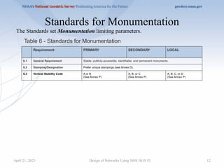
Standards for Monumentation
Designof Networks Using NOS NGS 92 12
Table 6 - Standards for Monumentation
Requirement PRIMARY SECONDARY LOCAL
6.1 General Requirement Stable, publicly-accessible, identifiable, and permanent monuments.
6.2 Stamping/Designation Prefer unique stampings (see Annex D).
6.3 Vertical Stability Code A or B
(See Annex P)
A, B, or C
(See Annex P)
A, B, C, or D
(See Annex P)
The Standards set Monumentation limiting parameters.
April 21, 2025
13.
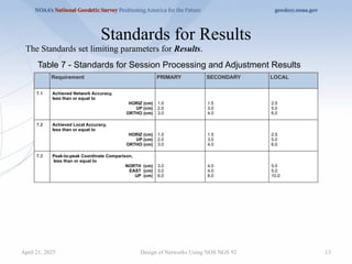
Standards for Results
Designof Networks Using NOS NGS 92 13
Table 7 - Standards for Session Processing and Adjustment Results
Requirement PRIMARY SECONDARY LOCAL
7.1 Achieved Network Accuracy,
less than or equal to
HORIZ (cm)
UP (cm)
ORTHO (cm)
1.0
2.0
3.0
1.5
3.0
4.0
2.5
5.0
6.0
7.2 Achieved Local Accuracy,
less than or equal to
HORIZ (cm)
UP (cm)
ORTHO (cm)
1.0
2.0
3.0
1.5
3.0
4.0
2.5
5.0
6.0
7.3 Peak-to-peak Coordinate Comparison,
less than or equal to
NORTH (cm)
EAST (cm)
UP (cm)
3.0
3.0
6.0
4.0
4.0
8.0
5.0
5.0
10.0
The Standards set limiting parameters for Results.
April 21, 2025
14.
14
Standards for Results
Designof Networks Using NOS NGS 92
Table 7 - Standards for Session Processing and Adjustment Results (continued)
7.4 Maximum Residuals per Vector, less than or
equal to, (in any adjustment)
DN (cm)
DE (cm)
DU (cm)
1.5 absolute value
1.5 absolute value
3.0 absolute value
2.0 absolute value
2.0 absolute value
4.0 absolute value
2.5 absolute value
2.5 absolute value
5.0 absolute value
7.5 Statistical Checks from Constrained
Adjustment
- Horizontal Constrained Adjustment.txt file
F-Statistic Test
Maximum Allowable Mark Constraint Ratio
N:
E:
U:
- Vertical Constrained Adjustment.txt file
F-Statistic Test
Maximum Allowable Mark Constraint Ratio
N:
E:
U:
PASS
3.0
3.0
3.0
PASS
n/a
n/a
3.0
April 21, 2025
15.
Standards for ValidOrthometric Heights
Design of Networks Using NOS NGS 92 15
Table 8 - Standards for Achieving Valid Orthometric Heights
Requirement PRIMARY SECONDARY LOCAL
8.1 Minimum Number Of Existing
Valid Bench Marks
2
8.2 Order/Class Of Existing Valid
Bench Marks
Adjusted Leveling (3rd Order or better), and GPS-derived Height Modernization, See
Specification 8.2 for detail.
8.3 Maximum Allowable Distance
From Newly Established Control
Mark to 2 Existing Valid Bench
Marks
Up to 50 km
The Standards set requirements for achieving Valid Orthometric Heights.
April 21, 2025
16.
Standards for Fieldand Office
Design of Networks Using NOS NGS 92 16
Table 9 - Standards for Field Equipment and Office Procedures
Requirement PRIMARY SECONDARY LOCAL
9.1 Tripod Type Fixed height or collapsible
fixed height
Fixed height or collapsible
fixed height
Fixed height, collapsible
fixed height, or adjustable
height
9.2 Antenna Calibration Listed on NGS Antenna Calibration page
9.3 RINEX version 2.11 or newer
9.4 Ephemeris
OPUS PP
GVX PP
GVX NRTK
GVX SRTK
Final Precise
Final Precise
Broadcast
Not allowed
Rapid
Rapid
Broadcast
Broadcast
Rapid
Rapid
Broadcast
Broadcast
The Standards set requirements for Field Equipment and Office Procedures.
April 21, 2025
17.
17
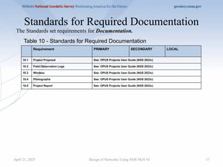
Standards for RequiredDocumentation
Design of Networks Using NOS NGS 92
Table 10 - Standards for Required Documentation
Requirement PRIMARY SECONDARY LOCAL
10.1 Project Proposal See: OPUS Projects User Guide (NGS 2023c)
10.2 Field Observation Logs See: OPUS Projects User Guide (NGS 2023c)
10.3 Windesc See: OPUS Projects User Guide (NGS 2023c)
10.4 Photographs See: OPUS Projects User Guide (NGS 2023c)
10.5 Project Report See: OPUS Projects User Guide (NGS 2023c)
The Standards set requirements for Documentation.
April 21, 2025
18.
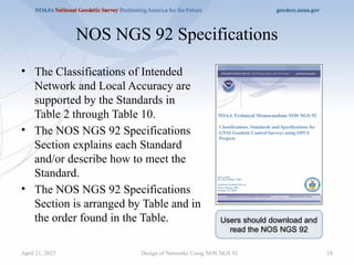
NOS NGS 92Specifications
• The Classifications of Intended
Network and Local Accuracy are
supported by the Standards in
Table 2 through Table 10.
• The NOS NGS 92 Specifications
Section explains each Standard
and/or describe how to meet the
Standard.
• The NOS NGS 92 Specifications
Section is arranged by Table and in
the order found in the Table.
Design of Networks Using NOS NGS 92 18
Users should download and
read the NOS NGS 92
April 21, 2025
19.
19
Review of aFew Key Concepts
Design of Networks Using NOS NGS 92
April 21, 2025
20.
20
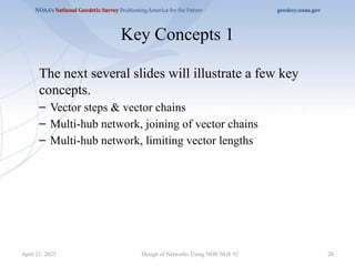
Key Concepts 1
Thenext several slides will illustrate a few key
concepts.
– Vector steps & vector chains
– Multi-hub network, joining of vector chains
– Multi-hub network, limiting vector lengths
Design of Networks Using NOS NGS 92
April 21, 2025
21.
21
Design of NetworksUsing NOS NGS 92
Vector Steps & Vector Chains
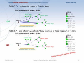
Table 5.7 – also effectively prohibits “daisy-chaining” or “leap-frogging” of vectors
Table 5.7 – Limits vector chains to 2 vector steps
Yes
No
2 vector steps 3 vector steps
4 vector steps
2 vector steps
2 vector steps
2 vector steps
April 21, 2025
22.
22
Design of NetworksUsing NOS NGS 92
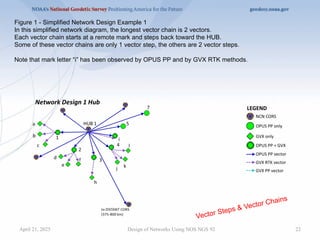
Figure 1 - Simplified Network Design Example 1
In this simplified network diagram, the longest vector chain is 2 vectors.
Each vector chain starts at a remote mark and steps back toward the HUB.
Some of these vector chains are only 1 vector step, the others are 2 vector steps.
Note that mark letter “i” has been observed by OPUS PP and by GVX RTK methods.
Vector Steps & Vector Chains
April 21, 2025
23.
23
Design of NetworksUsing NOS NGS 92
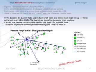
Figure 2 - Simplified Network Design Example 2
In this simplified network diagram, the longest vector chain is 2 vectors.
Each vector chain starts at a remote mark and steps back toward the HUB.
Some of these vector chains are only 1 vector step, the others are 2 vector steps.
In this diagram, it is evident that a vector chain which starts at a remote mark might have 2 (or more)
paths back to a HUB or HUBs. The dashed red lines show the vector chain junctions.
It shows how passive marks might be located from more than one GVX Base.
The vector lengths are becoming excessively long (see Table 5.5 and 5.6)
Joining of Vector Chains
April 21, 2025
24.
24
Design of NetworksUsing NOS NGS 92
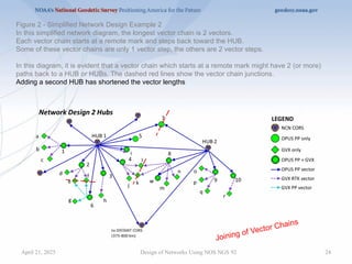
Figure 2 - Simplified Network Design Example 2
In this simplified network diagram, the longest vector chain is 2 vectors.
Each vector chain starts at a remote mark and steps back toward the HUB.
Some of these vector chains are only 1 vector step, the others are 2 vector steps.
In this diagram, it is evident that a vector chain which starts at a remote mark might have 2 (or more)
paths back to a HUB or HUBs. The dashed red lines show the vector chain junctions.
Adding a second HUB has shortened the vector lengths
Joining of Vector Chains
April 21, 2025
25.
25
Design of NetworksUsing NOS NGS 92
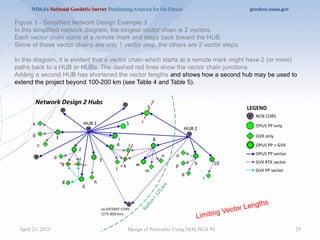
Figure 3 - Simplified Network Design Example 3
In this simplified network diagram, the longest vector chain is 2 vectors.
Each vector chain starts at a remote mark and steps back toward the HUB.
Some of these vector chains are only 1 vector step, the others are 2 vector steps.
In this diagram, it is evident that a vector chain which starts at a remote mark might have 2 (or more)
paths back to a HUB or HUBs. The dashed red lines show the vector chain junctions.
Adding a second HUB has shortened the vector lengths and shows how a second hub may be used to
extend the project beyond 100-200 km (see Table 4 and Table 5).
Limiting Vector Lengths
April 21, 2025
26.
26
Key Concepts 2
Thenext several slides will show examples of the
implementation of selected Standards of interest.
– Checkpoints (GVX Validation Stations)
– Minimum CORS arrangements
– Establishing Orthometric Heights
Design of Networks Using NOS NGS 92
April 21, 2025
27.
27
Design of NetworksUsing NOS NGS 92
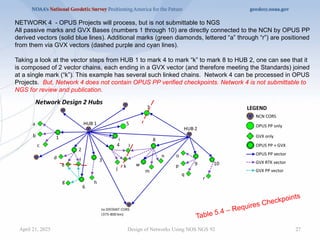
NETWORK 4 - OPUS Projects will process, but is not submittable to NGS
All passive marks and GVX Bases (numbers 1 through 10) are directly connected to the NCN by OPUS PP
derived vectors (solid blue lines). Additional marks (green diamonds, lettered “a” through “r”) are positioned
from them via GVX vectors (dashed purple and cyan lines).
Taking a look at the vector steps from HUB 1 to mark 4 to mark “k” to mark 8 to HUB 2, one can see that it
is composed of 2 vector chains, each ending in a GVX vector (and therefore meeting the Standards) joined
at a single mark (“k”). This example has several such linked chains. Network 4 can be processed in OPUS
Projects. But, Network 4 does not contain OPUS PP verified checkpoints. Network 4 is not submittable to
NGS for review and publication.
Table 5.4 – Requires Checkpoints
April 21, 2025
28.
28
Design of NetworksUsing NOS NGS 92
Table 5.4 – Requires Checkpoints
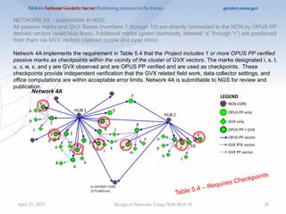
NETWORK 4A - submittable to NGS.
All passive marks and GVX Bases (numbers 1 through 10) are directly connected to the NCN by OPUS PP
derived vectors (solid blue lines). Additional marks (green diamonds, lettered “a” through “r”) are positioned
from them via GVX vectors (dashed purple and cyan lines).
Network 4A implements the requirement in Table 5.4 that the Project includes 1 or more OPUS PP verified
passive marks as checkpoints within the vicinity of the cluster of GVX vectors. The marks designated i, s, t,
u, v, w, x, and y are GVX observed and are OPUS PP verified and are used as checkpoints. These
checkpoints provide independent verification that the GVX related field work, data collector settings, and
office computations are within acceptable error limits. Network 4A is submittable to NGS for review and
publication.
April 21, 2025
29.
29
Design of NetworksUsing NOS NGS 92
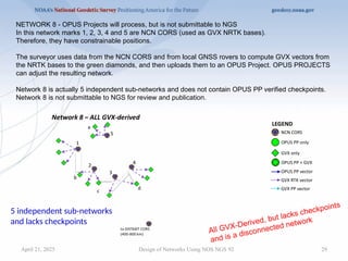
NETWORK 8 - OPUS Projects will process, but is not submittable to NGS
In this network marks 1, 2, 3, 4 and 5 are NCN CORS (used as GVX NRTK bases).
Therefore, they have constrainable positions.
The surveyor uses data from the NCN CORS and from local GNSS rovers to compute GVX vectors from
the NRTK bases to the green diamonds, and then uploads them to an OPUS Project. OPUS PROJECTS
can adjust the resulting network.
Network 8 is actually 5 independent sub-networks and does not contain OPUS PP verified checkpoints.
Network 8 is not submittable to NGS for review and publication.
All GVX-Derived, but lacks checkpoints
and is a disconnected network
5 independent sub-networks
and lacks checkpoints
April 21, 2025
30.
30
Design of NetworksUsing NOS NGS 92
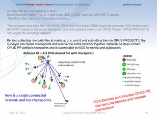
NETWORK 8A - submittable to NGS
In this network marks 1, 2, 3, 4 and 5 are NCN CORS (used as GVX NRTK bases).
Therefore, they have constrainable positions.
The surveyor uses data from the NCN CORS and from local GNSS rovers to compute GVX vectors from
the NRTK bases to the green diamonds, and then uploads them to an OPUS Project. OPUS PROJECTS
can adjust the resulting network.
By also collecting raw data files at marks a, b, c, and d and submitting them to OPUS PROJECTS, the
surveyor can create checkpoints and also tie the entire network together. Network 8A does contain
OPUS PP verified checkpoints and is submittable to NGS for review and publication.
GVX-Derived and includes OPUS PP,
now has checkpoints and network
connections.
Now is a single connected
network and has checkpoints.
April 21, 2025
31.
31
Design of NetworksUsing NOS NGS 92
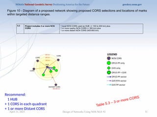
Figure 10 - Diagram of a proposed network showing proposed CORS selections and locations of marks
within targeted distance ranges.
5.3 Project includes 3 or more NCN
CORS
1 local NCN CORS used as HUB (< 100 to 200 km) plus
1 or more nearby NCN CORS (< 300 km) plus
1 or more distant NCN CORS (400-800 km)
Table 5.3 – 3 or more CORS
Recommend:
1 HUB
+ 1 CORS in each quadrant
+ 1 or more Distant CORS
April 21, 2025
32.
32
Design of NetworksUsing NOS NGS 92
8.1 Minimum Number Of Benchmarks 2
8.2 Order/Class Of Benchmarks Adjusted Leveling (3rd Order or better), and GPS-derived Height
Modernization. See Specification 8.2 for detail.
8.3 Maximum Allowable Distance
From Newly Established
Benchmarks to 2 Existing Valid
Benchmarks
Up to 50 km.
Figure 12 - Benchmark Location and Spacing Diagram
Establishing Orthometric Heights
Table 8 - Standards for Achieving Valid Orthometric Heights
Potentially cumbersome and error prone since the
overlaps can be visually difficult to determine.
April 21, 2025
33.
33
Design of NetworksUsing NOS NGS 92
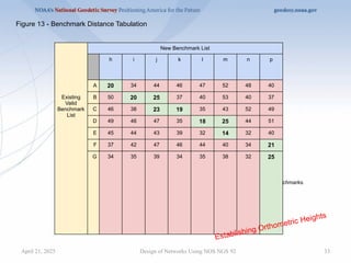
Note: all distances are tabulated in units of kilometers (km).
Color Code: 0 to 30 km = bold font w/green color, 30 km or more = normal font w/pink color.
A column with 2 or more bold font w/green color is within 30 km of 2 or more existing valid benchmarks.
Figure 13 - Benchmark Distance Tabulation
Existing
Valid
Benchmark
List
New Benchmark List
h i j k l m n p
A 20 34 44 46 47 52 48 40
B 50 20 25 37 40 53 40 37
C 46 38 23 19 35 43 52 49
D 49 46 47 35 18 25 44 51
E 45 44 43 39 32 14 32 40
F 37 42 47 46 44 40 34 21
G 34 35 39 34 35 38 32 25
Establishing Orthometric Heights
April 21, 2025
34.
34
Design of NetworksUsing NOS NGS 92
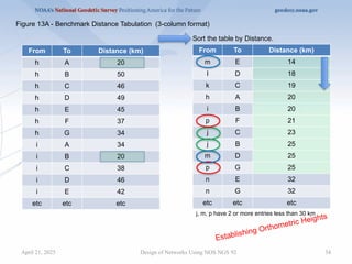
Figure 13A - Benchmark Distance Tabulation (3-column format)
From To Distance (km)
h A 20
h B 50
h C 46
h D 49
h E 45
h F 37
h G 34
i A 34
i B 20
i C 38
i D 46
i E 42
etc etc etc
Sort the table by Distance.
From To Distance (km)
m E 14
l D 18
k C 19
h A 20
i B 20
p F 21
j C 23
j B 25
m D 25
p G 25
n E 32
n G 32
etc etc etc
Establishing Orthometric Heights
j, m, p have 2 or more entries less than 30 km
April 21, 2025
35.
35
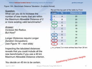
From To Distance(km)
h A 20
i B 20
j C 23
j B 25
k C 19
l D 18
m E 14
m D 25
p F 21
p G 25
Design of Networks Using NOS NGS 92
Re-sort the top part of the table by From
column.
j, m, p have 2 or more entries less than 30 km
Establishing Orthometric Heights
Figure 13A - Benchmark Distance Tabulation (3-column format)
Question:
What can you do to increase the
number of new marks that are within
the Maximum Allowable Distance of 2
or more existing valid benchmarks?
Answer:
Increase the Radius.
But How?
Longer Distances require Longer
Duration Occupations.
(see Figure 14 – next slide)
Inspecting the tabulated distances
reveals that you could include all the
new benchmarks if you use a 40 km
Maximum Allowable Distance criterion.
You decide on 45 km to be certain.
April 21, 2025
36.
36
Design of NetworksUsing NOS NGS 92
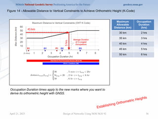
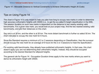
Figure 14 - Allowable Distance to Vertical Constraints to Achieve Orthometric Height (K-Code)
Establishing Orthometric Heights
Occupation Duration times apply to the new marks where you want to
derive its orthometric height with GNSS.
45 km
5
hrs
Average Duration
of 2 Longest
Occupations
Maximum
Allowable
Distance (km)
Occupation
Duration
(hrs)
30 km 2 hrs
35 km 3 hrs
40 km 4 hrs
45 km 5 hrs
50 km 6 hrs
April 21, 2025
37.
37
April 21, 2025Design of Networks Using NOS NGS 92
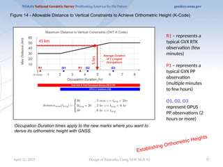
Figure 14 - Allowable Distance to Vertical Constraints to Achieve Orthometric Height (K-Code)
Establishing Orthometric Heights
Occupation Duration times apply to the new marks where you want to
derive its orthometric height with GNSS.
45 km
5
hrs
Average Duration
of 2 Longest
Occupations
R1 – represents a
typical GVX RTK
observation (few
minutes)
P1 – represents a
typical GVX PP
observation
(multiple minutes
to few hours)
O1, O2, O3
represent OPUS
PP observations (2
hours or more)
38.
38
Design of NetworksUsing NOS NGS 92
Figure 14 - Allowable Distance to Vertical Constraints to Achieve Orthometric Height (K-Code)
Establishing Orthometric Heights
Tips on Using Figure 14
The chart in Figure 14 is only meant to help you plan how long to occupy new marks in order to determine
high accuracy orthometric heights with GNSS (i.e., to get the so-called K-height classification in the IDB).
The session duration on such new marks is dependent on the distance to two nearby existing valid
benchmarks. For a given new mark, you would look at your project map, find the two nearest existing valid
benchmarks, and plot their distances on this chart.
Say one is at 30 km, and the other is at 50 km. The more distant benchmark is further so select 50 km. The
chart indicates to occupy the new mark for 6 hours.
Since the Standard requires a minimum of 2 or 3 sessions depending on Classification, then the surveyor
should occupy the new mark for an average of 6 hours for the 2 or 3 sessions to meet the Specification.
For existing valid benchmarks, they already have published orthometric heights. In that case, this chart
doesn't apply (you are not determining their orthometric height). Instead, they should be occupied
according to the desired Standard for ellipsoid heights.
The general rule for Figure 14: Occupation Duration times apply to the new marks where you want to
derive its orthometric height with GNSS.
April 21, 2025
40
Network Design Priorities
Thesurveyor seeks to create a survey network design that meets
the project’s goals and conforms to NOS NGS 92, in particular:
• Observe each mark using a selected method (Tables 2, 3, and 4)
• Minimize error propagation, maximize direct connections to the NSRS
(Table 5)
• Using quality monumentation (Table 6)
• Achieving the intended results (Table 7)
• Establishing good quality orthometric heights, where needed (Table 8)
• Using acceptable equipment and organization (Table 9)
• Documenting it for submission (Table 10)
Design of Networks Using NOS NGS 92
April 21, 2025
41.
41
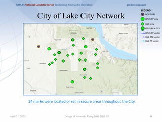
City of LakeCity Network
Project Goals
• Establish geodetic positions on 24 marks in the City of Lake City meeting the
SECONDARY Classification.
• Establish GPS-derived Orthometric heights on most or all of the new marks.
• Utilize the most efficient, safest, and most reliable observation methods.
Design of Networks Using NOS NGS 92
April 21, 2025
42.
42
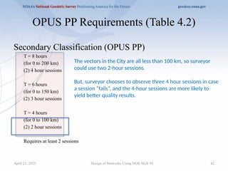
Secondary Classification (OPUSPP)
T = 8 hours
(for 0 to 200 km)
(2) 4 hour sessions
T = 6 hours
(for 0 to 150 km)
(2) 3 hour sessions
T = 4 hours
(for 0 to 100 km)
(2) 2 hour sessions
Requires at least 2 sessions
OPUS PP Requirements (Table 4.2)
Design of Networks Using NOS NGS 92
The vectors in the City are all less than 100 km, so surveyor
could use two 2-hour sessions.
But, surveyor chooses to observe three 4 hour sessions in case
a session “fails”, and the 4-hour sessions are more likely to
yield better quality results.
April 21, 2025
43.
43
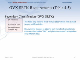
GVX SRTK Requirements(Table 4.5)
Secondary Classification (GVX SRTK)
(5) 5 minutes
Requires at least 2
occupations on a
different day.
Design of Networks Using NOS NGS 92
The Table only requires five 5-minute observations with at least
two on a different day.
But, surveyor chooses to observe six 5-minute observations in
case one observation “fails”, and plans to conduct 3 occupations
on 2 different days.
April 21, 2025
44.
44
City of LakeCity Network
Design of Networks Using NOS NGS 92
24 marks were located or set in secure areas throughout the City.
April 21, 2025
45.
45
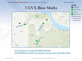
3 GVX BaseMarks
Design of Networks Using NOS NGS 92
Surveyor plans on using GVX SRTK Methods.
3 GVX SRTK Base Marks are located in secure areas with little traffic.
GVX Base 3
G
V
X
B
a
s
e
2
G
V
X
B
a
s
e
1
April 21, 2025
46.
46
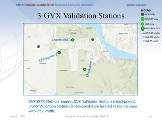
3 GVX ValidationStations
Design of Networks Using NOS NGS 92
GVX SRTK Method requires GVX Validation Stations (checkpoints).
3 GVX Validation Stations (checkpoints) are located in secure areas
with little traffic.
Checkpoint 2
Checkpoint 3
C
h
e
c
k
p
o
i
n
t
1
April 21, 2025
47.
47
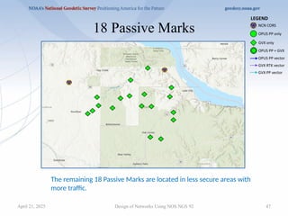
18 Passive Marks
Designof Networks Using NOS NGS 92
The remaining 18 Passive Marks are located in less secure areas with
more traffic.
April 21, 2025
48.
48
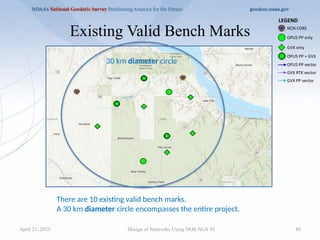
Existing Valid BenchMarks
Design of Networks Using NOS NGS 92
30 km diameter circle
There are 10 existing valid bench marks.
A 30 km diameter circle encompasses the entire project.
April 21, 2025
49.
49
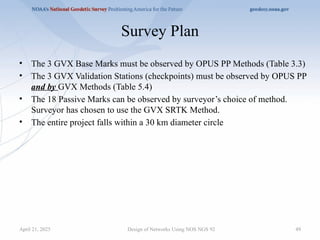
Survey Plan
• The3 GVX Base Marks must be observed by OPUS PP Methods (Table 3.3)
• The 3 GVX Validation Stations (checkpoints) must be observed by OPUS PP
and by GVX Methods (Table 5.4)
• The 18 Passive Marks can be observed by surveyor’s choice of method.
Surveyor has chosen to use the GVX SRTK Method.
• The entire project falls within a 30 km diameter circle
Design of Networks Using NOS NGS 92
April 21, 2025
50.
50
OPUS PP Vectors
Designof Networks Using NOS NGS 92
CORS 1
HUB
CORS 4
CORS 3
CORS 2
Distant CORS
GVX Base 3
G
V
X
B
a
s
e
2
G
V
X
B
a
s
e
1
Checkpoint 2
Checkpoint 3
C
h
e
c
k
p
o
i
n
t
1
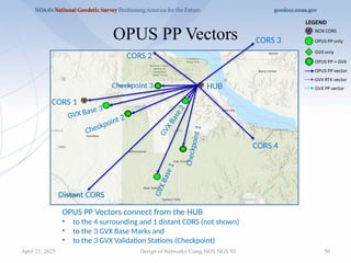
OPUS PP Vectors connect from the HUB
• to the 4 surrounding and 1 distant CORS (not shown)
• to the 3 GVX Base Marks and
• to the 3 GVX Validation Stations (Checkpoint)
April 21, 2025
51.
51
GVX SRTK Vectors
Designof Networks Using NOS NGS 92
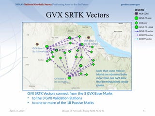
GVX SRTK Vectors connect from the 3 GVX Base Marks
• to the 3 GVX Validation Stations
• to one or more of the 18 Passive Marks
GVX Base 3
(to 10 marks)
GVX Base 2
(to 10 marks)
GVX Base 1
(to 10 marks)
Note that some Passive
Marks are observed from
more than one GVX Base
thus forming joined vector
chains.
April 21, 2025
54
OPUS PP SessionPlan
Design of Networks Using NOS NGS 92
Time 00 01 02 03 04 05 06 07 08 09 10 11 12 13 14 15 16 17 18 19 20 21 22 23
Day 1
Day 2
Day 3
(3) 4 hour occupations
offset
Table 4.1 requires a 3 to 21 hour offset.
Surveyor plans two 4-hour sessions each day, some in AM some in PM.
April 21, 2025
55.
55
OPUS PP SessionPlan
Design of Networks Using NOS NGS 92
Diagram
showing the
planned
sessions
Day 1 AM Day 1 PM Day 2 AM Day 2 PM Day 3 AM Day 3 PM Total OCC
GVX Base 1 3
GVX Base 2 3
GVX Base 3 3
Checkpoint 1 3
Checkpoint 2 3
Checkpoint 3 3
Total 18
Surveyor has 3 receivers, so can occupy 3 marks per session.
6 marks @ 3 marks per session = 18 data files
Every mark is observed 3 times.
Day 1
Day 2
Day 3
April 21, 2025
56.
56
GVX SRTK ObservationPlan
Design of Networks Using NOS NGS 92
Time 0
0
01 02 03 04 05 06 07 08 09 10 11 12 13 14 15 16 17 18 19 20 21 22 23
Day 1
Day 2
Day 3
(6) 5 minute occupations – 3 hour offset (Secondary)
3 hour offset 3 hour offset
Surveyor has 1 Base and 1 Rover receiver.
18 passive marks + 3 GVX Validation Stations = 21 marks
21 marks @ 6 occupations per mark = 126 observations
9 marks (the 3 checkpoints + 6 vector chain junctions) are double-observed = 54 observations.
Total of 126 + 54 = 180 GVX SRTK vectors on a total of 21 marks.
April 21, 2025
57.
57
GVX SRTK ObservationPlan
Design of Networks Using NOS NGS 92
To 7 AM 8 AM 9 AM 10 AM 11 AM 12 PM 13 PM 14 PM 15 PM 16 PM 17 PM 18 PM Total OCC
Point 1 3
Point 2 3
Point 3 3
Point 4 3
Point 5 3
Point 6 3
Point 7 3
Point 8 3
Point 9 3
Point 10 3
FROM: GVX BASE POINT 1, Day 4 for first group of 10 marks
Assume: 5 minute occupation + 10 minutes travel time = 15 minutes per mark
10 marks @ 15 minutes per mark = 150 minutes per observation cycle
Surveyor has 1 Base and 1 Rover receiver.
18 passive marks + 3 GVX Validation Stations = 21 marks
21 marks, 6 occupations per mark = 126 observations
9 marks are double-observed = 54 observations (to join vector chains)
Total of 180 GVX SRTK vectors
3 hour offset 3 hour offset
Day 4
April 21, 2025
58.
58
GVX SRTK ObservationPlan
Design of Networks Using NOS NGS 92
To 7 AM 8 AM 9 AM 10 AM 11 AM 12 PM 13 PM 14 PM 15 PM 16 PM 17 PM 18 PM Total OCC
Point 1 3
Point 2 3
Point 3 3
Point 4 3
Point 5 3
Point 6 3
Point 7 3
Point 8 3
Point 9 3
Point 10 3
FROM: GVX BASE POINT 1, Day 5 for first group of 10 marks
Assume: 5 minute occupation + 10 minutes travel time = 15 minutes
10 marks @ 15 minutes per mark = 150 minutes per observation cycle
Repeat similar pattern on Days 6 & 7
FROM: GVX BASE POINT 2, Day 6 for second group of 10 marks
FROM: GVX BASE POINT 2, Day 7 for second group of 10 marks
Repeat similar pattern on Days 8 & 9
FROM: GVX BASE POINT 3, Day 8 for third group of 10 marks
FROM: GVX BASE POINT 3, Day 9 for third group of 10 marks
Day 5
April 21, 2025
59.
59
Design of NetworksUsing NOS NGS 92
Orthometric Height Considerations
April 21, 2025
60.
60
Design of NetworksUsing NOS NGS 92
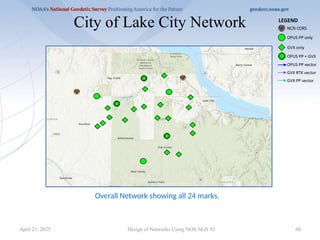
City of Lake City Network
Overall Network showing all 24 marks.
April 21, 2025
61.
61
Design of NetworksUsing NOS NGS 92
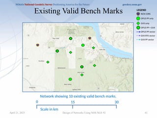
Existing Valid Bench Marks
0 30
15
Scale in km
Network showing 10 existing valid bench marks.
April 21, 2025
62.
62
Design of NetworksUsing NOS NGS 92
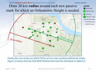
Draw 30 km radius around each new passive
mark for which an Orthometric Height is needed.
30 km radius
30 km radius
Clearly ALL new marks are within 30 km of 2 or more existing valid bench marks.
Figure 14 shows that the GVX SRTK Method will meet the Standards in Table 8.3.
April 21, 2025
64
Survey Design forGreatest Efficiency
• No absolute rule.
– Use OPUS PP methods to connect to the NSRS at CORS
(and other control) and to establish verifiable positions on
points from which shorter duration GVX methods can be
employed.
– A combination of methods (OPUS PP + GVX) is likely the
most efficient.
– But it all depends on local trade-offs, capability, and survey
requirements.
Design of Networks Using NOS NGS 92
April 21, 2025
65.
Project Proposal
• Itis the surveyor’s responsibility to plan the survey
project carefully, then submit a Project Proposal to
NGS to obtain a Tracking ID.
– NGS provides a web page and Sample Project Proposal
template for this purpose.
• The Project Proposal should address any need for
departure from the Standards and discuss the
justification for the departure.
Design of Networks Using NOS NGS 92 65
April 21, 2025
66.
66
Project Proposal Page
•https://geodesy.noaa.gov/SurveyProposal/
Design of Networks Using NOS NGS 92
Sample Project Proposals
Sample Project Reports
April 21, 2025
67.
Project Report
• Thesurveyor must analyze the survey project
carefully to verify adherence to the Standards as
listed in these Tables.
• Upon completion of the project analysis, the surveyor
must write a Project Report which summarizes and
discusses the results of the project.
• The Project Report must contain a tabulation of the
various Tables’requirements which the surveyor will
use to support successful achievement of at least the
LOCAL classification.
– NGS provides a Sample Project Report template for this
purpose. Design of Networks Using NOS NGS 92 67
April 21, 2025
68.
Project Report
• TheProject Report must discuss any departures from
Standards that were requested in advance, what final
impact these had on the project, and also discuss
unexpected circumstances which may justify post-
approval of additional departures from the Standards.
• The Project Report will be used by the NGS
acceptance personnel to efficiently determine whether
the requirements for at least the LOCAL
classification have been achieved.
Design of Networks Using NOS NGS 92 68
April 21, 2025
69.
Status
• The NOSNGS 92 document has received final
approval and is available for download from the
NGS Publications Library website.
Design of Networks Using NOS NGS 92 69
April 21, 2025
NOAA Technical Memorandum NOS NGS 92
Classifications, Standards and Specifications for GNSS Geodetic Control
Surveys using OPUS Projects
https://geodesy.noaa.gov/library/pdfs/NOAA_TM_NOS_NGS_0092.pdf
70.
70
The End
• Q& A discussion
Design of Networks Using NOS NGS 92
April 21, 2025
Editor's Notes
#1 Welcome to the NGS Webinar - Design of Networks Using NOS NGS 92.
#2 Our previous webinar on April 13, 2023 introduced the public to:
NOAA Technical Memorandum NOS NGS 92
Classifications Standards and Specifications for GNSS Geodetic Control Surveys using OPUS Projects
Following NOS NGS 92 is required for surveys to become part of the NGS Integrated Database.
The NOS NGS 92 document received final approval on October 23, 2024 and is available for download from NGS Publications library website.
NOAA Technical Memorandum NOS NGS 92
https://geodesy.noaa.gov/library/pdfs/NOAA_TM_NOS_NGS_0092.pdf
An updated set of slides is available from the NGS Presentations Library.
https://geodesy.noaa.gov/web/science_edu/presentations_library/
#3 Today’s webinar will:
Review NOS NGS 92 Tables 1 through 10,
Review a few Key Concepts,
Show an example survey design that implements the various NOS NGS 92 Standards and Specifications.
But, today’s webinar will not:
Process any data,
Analyze results, nor
Discuss the reportage of a project’s outcome.
#4 Review of NOS NGS 92 Tables 1 through 10
Tables are included here for convenience of reference.
Users should download and read the NOS NGS 92.
#5 The Standards define the following 3 Classifications of Network and Local Accuracy for GNSS geodetic control surveys which will be submitted to NGS for review and publication.
By following the requirements of Tables 2 through 10 the surveyor should expect to achieve the intended accuracies shown in Table 1.
Research and experience has shown that achieving accurate ellipsoid heights is more difficult than achieving accurate latitude and longitude, and that orthometric heights have additional uncertainty.
NGS will review any submitted survey that at least meets the requirements of the LOCAL Classification.
In keeping with current practice, the NGS Datasheet will not designate a Classification on the datasheet.
NGS has provided Primary and Secondary Classifications as recommended practices for surveys which aspire to achieve better than minimum standards.
#6 The Standards define 3 Mark Types and their Anticipated Usage as listed and described in Table 2.
A baseline may start at the NCN CORS and end at a Passive Mark.
Or, surveyors may choose to use GVX Methods. In that case a baseline chain may start at the NCN CORS, go to a GVX Base, then end at a Passive Mark.
#7 The Standards set Observation Methods for the 3 mark types.
If a mark is to be used as a GVX Base, it must be positioned using OPUS PP Methods.
A passive mark can be positioned using any of the 4 Observation Methods.
#8 Table 4 - Standards for Observation Requirements by Method
4.1 requires that start times of repeat occupations be offset (or staggered) by 3 hours to 21 hours.
This will ensure that diversity of satellite geometry and mitigation of multipath are accomplished, and also ensure that weather diversity is accomplished by observing on different days.
The term “offset” refers to the difference in the starting times of successive occupations.
Since satellite geometries essentially repeat at approximately every 12 hours, offset times of 3 to 21 hours are logical.
In the case of repeat sessions/occupations whose durations are between 5 hours and 24 hours, no specific offset is required since these durations already provide adequate satellite diversity and multipath mitigation.
4.2 lists the required TOTAL TIME (T) for OPUS PP observations.
Note that these Total Times are selected to reflect varying baseline distances and intended classifications.
Total Time is the sum of all the individual occupation times.
The Recommended Session Durations suggest several options to achieve the Total Time.
A few longer sessions are better than many short sessions.
#9 Table 4 - Standards for Observation Requirements by Method (continued)
4.3 lists the number and duration of sessions for the GVX PP Method.
Note that the occupation times are less than for the OPUS PP Method,
but so too are the allowable baseline distances, and 3 sessions are required rather than 2.
4.4 lists the number and duration of occupations for the GVX NRTK Method.
The Primary Classification requires 6 occupations with at least 3 occupations on a different day.
4.5 lists the number and duration of occupations for the GVX SRTK Method.
Note that GVX SRTK is not allowed in the Primary Classification.
And note that there are more occupations and that some must be on a different day.
#10 Table 5 – Standards for Network Design
It is not possible to set Standards that fit every possible situation.
In those unique circumstances, the Project Proposal should address the need for departure from the Standards and discuss the justification for the departure.
5.1 states that the NOAA CORS NETWORK (NCN) must be the hub for all OPUS Projects networks.
There are situations where the nearest NCN station is far away from the survey site.
A non-NCN mark can then be located very near the survey site and be used as a HUB to shorten the local vector ties from the HUB to the local marks.
The use of non-NCN marks as hubs should be avoided when possible and used only when necessary.
5.2 lists the spacing of hubs in a project.
There is little benefit in hub-to-hub spacing closer than 100 km and in general the NCN CORS are not spaced much closer than that.
Baselines longer than 200 km can be avoided by adding an NCN hub.
5.3 the selection of the minimum CORS for a project should follow these spacings.
Avoid Distant CORS further than 800 km, there is no benefit from greater distance and the shorter baselines are better.
5.4 There are many error sources in GVX PP, GVX NRTK, and GVX SRTK field and office operations that might lead to incorrect positions or heights.
To guard against such errors, it is required that:
If GVX vectors are uploaded to the Project, then the Project must include 1 or more OPUS PP verified passive marks as checkpoints within the vicinity of the cluster of GVX vectors.
But given the variability of survey conditions, terrain, accessibility, and other factors, it is not possible to set absolute requirements for quantity or proximity.
A checkpoint should be in close geographic proximity to the GVX observed marks and that sufficient checkpoints be included so that they can be routinely included in the GVX observations.
#11 Table 5 – Standards for Network Design (continued)
5.5 sets limits for the baseline distance for OPUS PP Methods.
The limit does not apply to HUB-to-NCN CORS because the HUB and NCN CORS will have 24-hour data files available and these long duration data files facilitate the longer baselines.
If hubs are spaced at 400 km or less (Table 5.2) the resulting baselines will seldom exceed these limits.
5.6 sets limits on baseline length for the GVX Methods.
5.7 sets limits on the number and type of vectors in a vector chain.
We will show examples later in the presentation.
5.8 sets minimum spacing between adjacent marks by Classification.
The purpose of submitting projects to NGS for review and publication is to provide primary, secondary, or local geodetic control.
Once that purpose is accomplished there is no gain by closer spacing.
The Standard limits the spacing of adjacent control marks to a reasonable spacing within which local surveying practices can reliably be followed.
5.9 sets limits on the beginning to ending of observations and how soon to submit the project.
#12 Table 6 - Standards for Monumentation
6.1 states that stable, publicly-accessible, identifiable, and permanent monuments be used in all projects.
And that Project Proposals Include a “typical monument” diagram in Project Proposal.
6.2 states that unique stampings are preferred.
Marks which are in close proximity and which have similar designations are often the source of misidentification and confusion.
NGS provides several tools to facilitate checking for nearby designations.
6.3 The stability of a mark is of utmost importance in geodetic surveys.
Annex P (see section A.29 Setting Class Code) lists vertical stability codes for many types of marks based on their settings.
The Project Proposal should discuss the need for lower stability marks based on local conditions.
#13 Table 7 - Standards for Session Processing and Adjustment Results
7.1 Network accuracy represents the uncertainty of a mark’s position relative to a geodetic reference frame (datum).
The maximum HORIZ, UP, and ORTHO network accuracies must be less than or equal to the allowed value in Table 7.1.
If any values exceed the allowed value, the survey has not met the intended classification.
7.2 Local accuracy represents the uncertainty of a mark’s position relative to other directly connected, adjacent control points.
The maximum HORIZ, UP, and ORTHO local accuracy must be less than or equal to the allowed value in Table 7.2.
If any values exceed the allowed value, the survey has not met the intended classification.
7.3 Sets maximum peak-to-peak coordinate comparisons.
If any values exceed the allowed value, the survey has not met the intended classification.
#14 Standards for Session Processing and Adjustment Results (continued)
7.4 The maximum residuals per vector are tabulated in the PREPLT2 output.
The PREPLT2 output is summarized from the detailed Processing Log (.sum) file in the adjustment.
Note that these are absolute values.
7.5 sets statistical quality checks.
The F-Statistic Test is listed in the Horizontal Constrained Adjustment (.TXT) and in the Vertical Constrained Adjustment (.TXT).
The Mark Constraint Ratios are listed in the Horizontal Constrained Adjustment (.TXT) and in the Vertical Constrained Adjustment (.TXT).
#15 Table 8 - Standards for Achieving Valid Orthometric Heights
General Limitation
The requirements of Table 8 are applicable only to surveys which seek to establish valid orthometric heights via GNSS Geodetic Control Surveys using OPUS Projects.
The Project Proposal must state whether the project proposes to establish valid orthometric heights and
The Project Report must state the surveyor's intent regarding the orthometric heights in the project.
8.1 requires that new benchmarks must be within the proximity requirements of Standard 8.3 of at least 2 existing valid benchmarks.
8.2 requires that existing valid benchmarks be chosen from a limited set of acceptable orthometric height types.
The OPUS Projects User Guide has a very extensive discussion of these orthometric height types with examples.
8.3 sets the maximum allowable distance from new benchmarks to existing valid benchmarks.
This presentation will show examples later.
#16 Table 9 - Standards for Equipment Used in Field Observations and Office Procedures
9.1 requires either fixed height, collapsible fixed height, or adjustable height tripods in each Classification.
All tripods and level bubbles in good repair and adjusted.
Carefully measured tripod heights are required.
9.2 NGS maintains a list of known NGS-calibrated GPS/GNSS antennas in an ANTCAL file.
Antennas which are not on this list are not allowed by the Standard.
9.3 GNSS raw data in RINEX version 2.11 or newer is acceptable for OPUS PP methods.
GVX methods may use whatever raw data file the non-NGS software requires.
9.4 Projects submitted to the NGS for review and publication should use the ephemeris version as listed by method in Table 9 to achieve the desired Intended Classification.
#17 Table 10 makes it clear that certain supporting documentation is required.
The OPUS Projects User Guide has detailed information.
#18 The Classifications of Intended Network and Local Accuracy are supported by the Standards in Table 2 through Table 10.
The NOS NGS 92 Specifications explain each Standard and/or describe how to meet the Standard.
The NOS NGS 92 Specifications section is arranged by Table and in the order found in the Table.
#20 The next several slides will illustrate a few key concepts.
Vector steps & vector chains
Multi-hub network, joining of vector chains
Multi-hub network, limiting vector lengths
#21 Table 5.7 – Limits vector chains to 2 vector steps, and also effectively prohibits “daisy-chaining” or “leap-frogging” of vectors.
By making direct connections from the NCN to a GVX Base Station, error-propagation is minimized.
Connecting several GVX Base stations and vectors in succession provides many opportunities for error accumulation.
#22 In this simplified network diagram, the longest vector chain is 2 vectors.
Each vector chain starts at a remote mark and steps back toward the HUB.
Some of these vector chains are only 1 vector step, the others are 2 vector steps.
Note that mark letter “i” has been observed by OPUS PP and by GVX RTK methods, which is an acceptable practice.
#23 In this diagram, it is evident that a vector chain which starts at a remote mark might have 2 (or more) paths back to a HUB or HUBs.
The dashed red lines show the vector chain junctions.
It shows how passive marks might be located from more than one GVX Base.
The vector lengths are becoming excessively long (see Table 5.5 and 5.6)
#24 When projects extend about 100 km or more from HUB 1, it may be advantageous to include a HUB 2.
Adding a second HUB has shortened the vector lengths and vectors from HUB 2 may attach to the same marks as vectors from HUB 1, making joined vector chains possible.
#25 Vectors from HUB 2 to marks 8, 9, and 10 are shorter than would have been the case in a 1 HUB project.
Adding a second hub is used to extend the project beyond 100-200 km (see Table 4 and Table 5) thereby limiting the length of the vectors.
#26 The next several slides will show examples of the implementation of selected Standards of interest.
Checkpoints (RTN Validation Stations)
Minimum CORS arrangements
Establishing Orthometric Heights
#27 NETWORK 4 - OPUS Projects will process, but is not submittable to NGS
All passive marks and GVX Bases (numbers 1 through 10) are directly connected to the NCN by OPUS PP derived vectors (solid blue lines). Additional marks (green diamonds, lettered “a” through “r”) are positioned from them via GVX vectors (dashed purple and cyan lines).
Taking a look at the vector steps from HUB 1 to mark 4 to mark “k” to mark 8 to HUB 2, one can see that it is composed of 2 vector chains, each ending in a GVX vector (and therefore meeting the Standards) joined at a single mark (“k”). This example has several such linked vector chains.
Network 4 can be processed in OPUS Projects.
But, Network 4 does not contain OPUS PP verified checkpoints.
Network 4 is not submittable to NGS for review and publication.
#28 Network 4A implements the requirement in Table 5.4 that “Project includes 1 or more OPUS PP verified passive marks as checkpoints within the vicinity of the cluster of GVX vectors”. The marks designated i, s, t, u, v, w, x, and y are GVX observed and OPUS PP verified and are used as checkpoints.
These checkpoints provide independent verification that the GVX related field work, data collector settings, and office computations are within acceptable error limits.
Network 4A is submittable to NGS for review and publication.
#29 NETWORK 8 - OPUS Projects will process, but is not submittable to NGS
In this network marks 1, 2, 3, 4 and 5 are NCN CORS (used as GVX NRTK bases).
Therefore, they have constrainable positions.
The surveyor uses data from the NCN CORS and from local GNSS rovers to compute GVX vectors from the NRTK bases to the green diamonds, and then uploads them to an OPUS Project.
OPUS PROJECTS can adjust the resulting network.
Specifications require that “…a “survey” or “project” is a single adjusted network. A survey or project cannot contain disconnected sub-networks. All marks must be connected by vectors within a single network.”
Network 8 is actually 5 independent sub-networks and does not contain OPUS PP verified checkpoints.
Network 8 is not submittable to NGS for review and publication.
#30 By also collecting raw data files at marks a, b, c, and d and submitting them to OPUS PROJECTS, the surveyor can create checkpoints and also tie the entire network together.
Network 8A does contain OPUS PP verified checkpoints and is submittable to NGS for review and publication.
#31 5.3 requires 3 or more CORS spaced within designated distance ranges.
Figure 10 - This diagram of a proposed network shows proposed CORS selections and locations of marks within targeted distance ranges.
Given the non-uniform distribution of NCN CORS, project mark locations, and other considerations, adherence to this Standard can best be judged by selecting a local CORS to use as HUB, then selecting the needed surrounding CORS, and finally selecting a distant CORS.
After these selections are made, one can measure:
from the proposed local HUB to the project marks (should be less than 100 to 200 km)
from the proposed local HUB to the nearby CORS (should be less than 300 km)
from the proposed local HUB to the distant CORS (should be 400 km to 800 km)
#32 Figure 12 - Benchmark Location and Spacing Diagram
For small projects
An easy way to determine if a proposed new benchmark lies within the allowable maximum distance to 2 or more existing valid benchmarks is to make a scaled plot, then draw circles of the appropriate radius around each existing valid benchmark.
If the proposed new benchmark lies within 2 or more overlapping circles, then it meets the Standard.
However, this is potentially cumbersome and error prone since the overlaps can be visually difficult to determine.
#33 Figure 13 - Benchmark Distance Tabulation
For small projects
An alternative method is to measure on the scaled plot from a proposed new benchmark to each existing valid benchmark and tabulate the results in a multi-column format.
By inspection, one can find which new benchmarks are within the maximum allowable distance to 2 or more existing valid benchmarks.
In this example, colors were applied to the table.
#34 Figure 13A - Benchmark Distance Tabulation (3-column format)
Since every mark in a project has a coordinate, the distance between any pair of marks can be computed by coordinate geometry.
A 3-column design for the output will allow easy sorting.
First, sort by Distance.
The small distances will be easily located.
And the marks which have 2 or more entries in the table within the allowable distance can be found by inspection.
Here shown in colored ellipses.
#35 Figure 13A - Benchmark Distance Tabulation (3-column format)
For larger projects, a second sorting of just the top part of the table will put the FROM marks in alphabetical order and make selecting marks having 2 or more entries easier.
Here shown in colored ellipses.
It may advantageous to develop a computerized algorithm to automate the identification of those new benchmarks that fall within the maximum allowable distance to 2 or more existing valid benchmarks.
If you need more new benchmarks to meet the Standard, then a larger radius will be needed.
Let’s assume 45 km will be sufficient.
#36 Figure 14 - Allowable Distance to Vertical Constraints to Achieve Orthometric Height (K-Code)
This figure shows a chart which relates the Maximum Allowable Distance to the Occupation Duration.
As an example, your Benchmark Tabulation shows that you need a 45 km allowable distance to achieve your goals.
The chart shows that you would need to occupy each of the new benchmarks for an average of 5 hours.
#37 You can also use Figure 14 for Methods other than OPUS PP.
R1 – represents a typical GVX RTK observation (few minutes)
P1 – represents a typical GVX PP observation (multiple minutes to few hours)
O1, O2, O3 represent OPUS PP observations (2 hours or more)
#38 Tips on Using Figure 14
The chart in Figure 14 is only meant to help you plan how long to occupy new marks in order to determine high accuracy orthometric heights with GNSS (i.e., to get the so-called K-height classification in the IDB). The session duration on such new marks is dependent on the distance to two nearby existing valid benchmarks. For a given new mark, you would look at your project map, find the two nearest existing valid benchmarks, and plot their distances on this chart.
Say one is at 30 km, and the other is at 50 km. The more distant benchmark is further so select 50 km. The chart indicates to occupy the new mark for 6 hours.
Since the Standard requires a minimum of 2 or 3 sessions depending on Classification, then the surveyor should occupy the new mark for an average of 6 hours for the 2 or 3 sessions to meet the Specification.
For existing valid benchmarks, they already have published orthometric heights. In that case, this chart doesn't apply (you are not determining their orthometric height). Instead, they should be occupied according to the desired Standard for ellipsoid heights.
The general rule for Figure 14: Occupation Duration times apply to the new marks where you want to derive its orthometric height with GNSS.
#40 The surveyor seeks to create a survey network design that meets the project’s goals and conforms to NOS NGS 92, in particular:
Observe each mark using a selected method (Tables 2, 3, and 4)
Minimize error propagation, maximize direct connections to the NSRS (Table 5)
Using quality monumentation (Table 6)
Achieving the intended results (Table 7)
Establishing good quality orthometric heights, where needed (Table 8)
Using acceptable equipment and organization (Table 9)
Documenting it for submission (Table 10)
#41 Project Goals
Establish geodetic positions on 24 marks in the City of Lake City meeting the SECONDARY Classification.
Establish GPS-derived Orthometric heights on most or all of the new marks.
Utilize the most efficient, safest, and most reliable observation methods.
#42 Table 4.2 lists the OPUS PP Method Requirements for SECONDARY Classification.
The vectors in the City are all less than 100 km, so surveyor could use two 2-hour sessions.
But, surveyor chooses to observe three 4 hour sessions in case a session “fails”, and the 4-hour sessions are more likely to yield better quality results.
#43 Table 4.5 lists the GVX SRTK Method Requirements for SECONDARY Classification.
The Table only requires five 5-minute observations with at least two on a different day.
But, surveyor chooses to observe six 5-minute observations in case one observation “fails”, and plans to conduct 3 occupations on 2 different days.
#44 24 marks were located or set in secure areas throughout the City.
There are 2 nearby CORS.
#45 Surveyor plans on using GVX SRTK Methods.
3 GVX SRTK Base Marks are located in secure areas with little traffic.
#46 GVX SRTK Method requires GVX Validation Stations (checkpoints).
3 GVX Validation Stations (checkpoints) are located in secure areas with little traffic.
#47 18 Passive Marks are located in less secure areas with more traffic.
#48 There are 10 existing valid bench marks.
A 30 km circle encompasses the entire project.
#49 The 3 GVX Base Marks must be observed by OPUS PP Methods (Table 3.3)
The 3 GVX Validation Stations (checkpoints) must be observed by OPUS PP and by GVX Methods (Table 5.4)
The 18 Passive Marks can be observed by surveyor’s choice of method. Surveyor has chosen to use the GVX SRTK Method.
The entire project falls within a 30 km diameter circle
#50 OPUS PP Vectors connect from the HUB
to the 4 surrounding CORS and 1 distant CORS (not shown)
to the 3 GVX Base Marks and
to the 3 GVX Validation Stations (Checkpoint)
#51 GVX SRTK Vectors connect from the 3 GVX Base Marks
to the 3 GVX Validation Stations
to one or more of the 18 Passive Marks
Note that some Passive Marks are observed from more than one GVX Base thus forming joined vector chains.
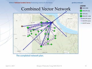
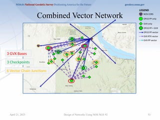
#53 Completed Plan includes
3 GVX Bases
3 Checkpoints
6 Vector chain junctions
#54 Table 4.1 requires a 3 to 21 hour offset.
Surveyor plans two 4-hour sessions each day, some in AM some in PM
#55 Surveyor has 3 receivers, so can occupy 3 marks per session.
6 marks @ 3 marks per session = 18 data files
Every mark is observed 3 times.
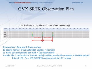
#56 Surveyor has 1 Base and 1 Rover receiver.
18 passive marks + 3 GVX Validation Stations = 21 marks
21 marks @ 6 occupations per mark = 126 observations
9 marks (the 3 checkpoints + 6 vector chain junctions) are double-observed = 54 observations.
Total of 21+126+54=180 GVX SRTK vectors on a total of 21 marks.
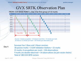
#57 Assume: 5 minute occupation + 10 minutes travel time = 15 minutes per mark
10 marks @ 15 minutes per mark = 150 minutes per observation cycle
This will result in the required 3 hour offset between repeat occupations.
On Day 4, surveyor will observe 10 marks, three times with three hour offset.
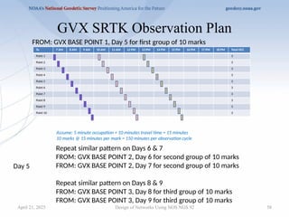
#58 On Day 5, surveyor will observe the same 10 marks, three times with three hour offset.
Repeat similar pattern
FROM: GVX BASE POINT 2, Day 6 for second group of 10 marks
FROM: GVX BASE POINT 2, Day 7 for second group of 10 marks
and
FROM: GVX BASE POINT 3, Day 8 for third group of 10 marks
FROM: GVX BASE POINT 3, Day 9 for third group of 10 marks
#62 After drawing 30 km radius arcs centered on the new marks near the edges of the network, it is clear that ALL new marks are within 30 km of 2 or more existing valid bench marks.
Figure 14 shows that the GVX SRTK Method will meet the Standards in Table 8.3.
#64 No absolute rule.
Use OPUS PP methods to connect to the NSRS at CORS (and other control) and to establish verifiable positions on points from which shorter duration GVX methods can be employed.
A combination of methods (OPUS PP + GVX) is likely the most efficient.
But it all depends on local trade-offs, capability, and survey requirements.
#65 It is the surveyor’s responsibility to plan the survey project carefully, then submit a Project Proposal to NGS to obtain a Tracking ID.
NGS provides a web page and Sample Project Proposal template for this purpose.
The Project Proposal should address any need for departure from the Standards and discuss the justification for the departure.
#66 The NGS Project Proposal web page has link to sample Project Proposal and Project Reports.
#67 The surveyor must analyze the survey project carefully to verify adherence to the Standards as listed in these Tables.
Upon completion of the project analysis, the surveyor must write a Project Report which summarizes and discusses the results of the project.
The Project Report must contain a tabulation of the various Tables’ requirements which the surveyor will use to support successful achievement of at least the LOCAL classification.
NGS provides a Sample Project Report template for this purpose.
#68 The Project Report must discuss any departures from Standards that were requested in advance, what final impact these had on the project, and also discuss unexpected circumstances which may justify post-approval of additional departures from the Standards.
The Project Report will be used by the NGS acceptance personnel to efficiently determine whether the requirements forat least the LOCAL classification have been achieved.
#69 The NOS NGS 92 document has received final approval and is available for download from the NGS Publications Library website.