
Recommended
Recommended
More Related Content
What's hot
What's hot (20)
Similar to Nissan forklift electric 1 q2 series service repair manual
Similar to Nissan forklift electric 1 q2 series service repair manual (19)
More from fjsjekfkselmm
More from fjsjekfkselmm (20)
Recently uploaded
Recently uploaded (20)
Nissan forklift electric 1 q2 series service repair manual
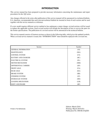
- 1. INTRODUCTION This service manual has been prepared to provide necessary information concerning the maintenance and repair procedures for the 1Q2 series. Any changes effected in the series after publication of this service manual will be announced in a technical bulletin. It is, therefore, recommended that each relevant technical bulletin be inserted in front of each section and be used together with the service manual as a reference. If a new model requires different service method or has undergone a major change, revised sections will be issued to replace the applicable sections. Each revised section will include the description of how to service the parts for the former specifications. The publication of a revised section will be announced in the technical bulletin. This service manual consists of fourteen sections as shown in the following table, which gives the updated symbols. When a revised service manual is issued, this “INTRODUCTION” sheet should be replaced with a revised one. Edition: March 2010 Printed in The Netherlands Printing: March 2010 (01) Publication No. SM10E-01Q2E0 Section Symbol GENERAL INFORMATION (GI) MAINTENANCE (MA) CONTROL SYSTEM (CS) BATTERY AND CHARGER (BC) ELECTRICAL SYSTEM (EL) MOTOR MECHANISM (MM) DIFFERENTIAL CARRIER (DF) FRONT AXLE (FA) REAR AXLE (RA) BRAKE SYSTEM (BR) STEERING SYSTEM (ST) HYDRAULIC SYSTEM (HD) LOADING MECHANISM (LM) BODY AND FRAME (BF)
- 2. Revised November 2008 FOREWORD © 2010 NFE B.V. Printed in The Netherlands This manual contains maintenance and repair procedures. In order to assure your safety and the efficient functioning of the lift truck, this manual should be read thoroughly. It is especially important that the PRECAUTIONS in the GI section be completely understood before starting any repair task. All information in this manual is based on the latest product information at the time of publication. The right is reserved to make changes in specifications and methods at any time without notice. IMPORTANT SAFETY NOTICE The proper performance of service is essential for both the safety of the technician and the efficient functioning of the lift truck. The service methods in this Service Manual are described in such a manner that the service may be performed safely and accurately. Service varies with the procedures used, the skills of the technician and the tools and parts available. Accordingly, anyone using service procedures, tools or parts which are not specifically recommended by NISSAN must first be completely satisfied that neither personal safety nor the lift truck's safety will be jeopardized by the service method selected. No modifications or alterations to a powered industrial truck, which may affect, for example, capacity, stability or safety requirements of the truck shall be made without the prior written approval of NISSAN, its authorized representative, or a successor thereof. Contact an authorized NISSAN FORKLIFT dealer before making any modification or alteration to your industrial truck that may affect, for example braking, steering, visibility and the addition of removable attachments. After getting approval of NISSAN, its authorized representative, or a successor thereof, capacity plate, decals tags and operation and maintenance handbooks shall also be changed to the appropriate one. Only in the event that NISSAN is no longer in business and there is no successor in the interest to the business, the user may arrange for a modification or alteration to a powered industrial truck, provided, however, that the user shall: A. Arrange for the modification or alteration to be designed, tested and implemented by an engineer(s) expert in industrial trucks and their safety; B. Maintain a permanent record of the design, test(s) and implementation of the modification or alteration; C. Approve and make appropriate changes to the capacity plate(s), decals, tags and Instruction Handbook; D. Affix a permanent and readily visible label to the truck stating the manner in which the truck has been modified or altered together with the date of the modification or alteration, and the name and address of the organization that accomplished the tasks.
- 3. SECTION ST STEERING SYSTEM CONTENTS SERVICE DATA AND SPECIFICATIONS .......... ST-2 General Specifications ................................... ST-2 Tightening Torque .......................................... ST-2 TROUBLE DIAGNOSES AND CORRECTIONS .................................................. ST-3 List of Diagnoses ............................................ ST-3 PRECAUTIONS AND PREPARATION .............. ST-4 Precautions .................................................... ST-4 Special Service Tools ..................................... ST-4 STEERING WHEEL ............................................ ST-5 Component Parts ........................................... ST-5 Removal ......................................................... ST-5 Inspection ....................................................... ST-5 Installation ...................................................... ST-6 Inspection After Installation ............................ ST-6 STEERING COLUMN ASSEMBLY .................... ST-7 Construction ................................................... ST-7 Installation ...................................................... ST-8 PS VALVE ............................................................ST-9 Component Parts ............................................ST-9 Disassembly ..................................................ST-10 Inspection ......................................................ST-11 Assembly .......................................................ST-12 Trouble Diagnoses and Corrections ..............ST-15 PS CYLINDER ...................................................ST-17 Construction ..................................................ST-17 Removal and Installation ...............................ST-17 Disassembly and Assembly ..........................ST-18 PIPING ...............................................................ST-20 Component Parts ..........................................ST-20 Removal ........................................................ST-22 Inspection ......................................................ST-22 Installation .....................................................ST-22
- 4. ST-2 SERVICE DATA AND SPECIFICATIONS SERVICE DATA AND SPECIFICATIONS General Specifications Tightening Torque Power steering system Full hydraulic system Steering wheel Outer diameter mm (in) 320 (12.60) Number of turns (Lock to lock) 4.5 Maximum steering angle Inner wheel degrees 78.5 Outer wheel degrees 56.4 PS valve System Full hydraulic load sensing PS valve Type PS valve with ultra-low input valve (Plugged star type) Discharge cm3 /rev 69 PS power cylinder Rod diameter mm (in) 40 (1.57) Inner diameter mm (in) 60 (2.36) Outer diameter mm (in) 72 (2.83) Stroke mm (in) 196 (7.72) PS control Load sensing type Relief pressure MPa (bar, kg/cm2, psi) 9 (93, 95, 1,351) Specified oil Hydraulic oil I.S.O. VG32 (Standard forklift) Hydraulic oil I.S.O. VG15 (Cold storage forklift) Theoretical tracking ability (normal) rev/sec 2.0 Unit N•m kg-m ft-lb Steering wheel nut 18 - 22 1.9 - 2.2 14 - 16 Steering column cover bolt 1.5 - 2.0 0.16 - 0.20 1.1 - 1.4 Steering column shaft upper/lower joint pinch bolt 16 - 22 1.6 - 2.2 12 - 16 Steering column bracket bolt 27 - 36 2.8 - 3.7 20 - 27 Tilt lock lever securing bolt 8 - 11 0.9 - 1.1 6 - 8 PS valve bolt 30 - 40 3.1 - 4.0 23 - 29 PS valve bracket 69 - 78 7.0 - 8.0 51 - 58 PS cylinder mounting bolt 140 - 190 14 - 19 103 - 140 PS piping 40 - 58 4.1 - 5.9 30 - 43 PS piping to PS cylinder 39 - 43 4.0 - 4.4 29 - 32 PS piping to PS correction solenoid valve 39 - 43 4.0 - 4.4 29 - 32
- 5. ST-3 TROUBLE DIAGNOSES AND CORRECTIONS TROUBLE DIAGNOSES AND CORRECTIONS List of Diagnoses CAUTION: The following tables list only typical examples. To perform an accurate diagnosis, carefully listen to the user's complaints and check the actual vehicle to fully understand under what conditions the symptoms occur. NOTE: The steering system is directly related to the rear axle, be sure to diagnose the steering system by referring to RA section. Symptom Possible causes Corrective action Vibration, impact, instability of steering wheel Insufficient tire air pressure Adjust. Worn kingpin and needle bearing Replace. Excessive free play of tie rod and clevis pin Replace. Worn and loose spherical bushing Replace. Insufficiently adjusted or worn wheel bearing Adjust or replace. Worn kingpin thrust bearing Replace. Deformed or unevenly worn tires and road wheels Repair or replace. Loose joint Tighten. Loose spool of PS valve Tighten and replace. Damaged control valve, broken or deteriorated coil spring Replace. Excessive steering wheel effort Insufficient lubrication of kingpin Grease and replace malfunctioning parts. Foreign objects, insufficient oil Replace and fill oil. Deformed or interfered tie-rod bar Repair or replace. Insufficiently adjusted or worn wheel bearing Adjust or replace. Insufficient oil in oil tank Fill. Insufficient air bleeding Bleeding. Oil leakage from hoses and tubes, or clogging of oil passage Replace or clean. Insufficient hydraulic pressure Refer to the following “Insufficient hydraulic pressure”. Damaged control valve Replace. Damaged piston seal of PS cylinder Replace. Insufficient hydraulic pressure Oil leakage from hoses, tubes and joints, or clogging of oil passage Replace or clean. Malfunctioning hydraulic pump Refer to “TROUBLE DIAGNOSIS AND CORRECTIONS” in HD section. Vehicle rolling away in a certain direction Insufficient matching of left and right tires Adjust or replace. Brake adjustment incorrect Adjust. Vehicle wobbling (straight-line instability) Malfunctioning PS valve Replace. Worn or inappropriately adjusted wheel bearing Adjust or replace. Loose road wheel Tighten. Excessive free play of tie-rod clevis pin Replace. Deformed road wheel Replace. Excessive free play of steering wheel Worn steering shaft and PS valve-connecting spline Replace. Loose PS valve mounting bolt Tighten. Inappropriately adjusted wheel bearing Adjust. Inappropriate steering wheel return travel Malfunctioning spool Disassemble, clean, and replace. Inappropriate centering spring of PS valve Replace. Inappropriate wheel alignment Adjust. Insufficient tire air pressure Adjust.
- 6. ST-4 PRECAUTIONS AND PREPARATION PRECAUTIONS AND PREPARATION Precautions CAUTION: • Be extremely careful when hoisting and moving heavy objects. These can be extremely dangerous operations. • Always clean working area to prevent foreign matter from getting into parts being assembled or serviced. • Use a paper rag rather than a cloth when wiping clean parts. Use of a cloth rag may leave lint or other foreign matter on parts being wiped. • When disassembling or servicing units or parts of a vehicle, park it on solid and level ground and chock the wheels. Failure to do so may cause the vehicle to move unexpectedly. Also, be sure to disconnect battery plug in advance. • Always perform disassembling or servicing the steering ORBITROL and power steering cylinder assembly, with clean hands. It is important to prevent the parts from contamination by dirt or other foreign matter. • When removing or installing any unit, make sure that the vehicle is placed in the straight-ahead driving position. • After tightening castle nuts, be sure to install and clinch a new cotter pin. NOTE: • This ST section describes inspection and maintenance procedures for the steering system mechanism. • For troubleshooting and maintenance of the electrically controlled power steering system, refer to CS section. • Refer to EL section for meter panel and turn signal lamp lever switch inspection. • Refer to RA section for servicing the rear axle assembly. • When disassembling or servicing designated parts, be sure to use special service tools. • Refer to CS section for the pump motor controller. Special Service Tools Tool number Tool name Description ST27180000 Steering wheel puller Removing steering wheel
- 7. ST-5 STEERING WHEEL STEERING WHEEL Component Parts Removal 1. Remove the horn button. 2. Remove the steering wheel retaining nut and remove the steering wheel using the steering wheel puller. CAUTION: Do not tap steering wheel mounting nut with hammer. It causes the malfunction of the combination switch. Inspection 1. Check the steering wheel for any damages, cracks or deformation and replace it as necessary. 2. If the serration section is deformed, replace it. (Check steering shaft serration also.) Contact plate Washer Knob shaft Contact plate bracket Steering wheel nut Knob bushing Horn button spring Horn button Wahser Grommet Knob Nut Steering wheel STT0089L
- 8. ST-6 STEERING WHEEL Installation The combination switch auto return function is operated by steering wheel operation. In addition, a full hydraulic steering system is adopted, which features a function that corrects the knob position by detecting the steering wheel rotation and road wheel steering angle (knob position control system). It is necessary to set steering wheel and steering wheel angle sensor. The following paragraphs explain that procedure. 1. Position the “P” section of the combination switch as shown and apply grease (NAV-1) to the “Q” section (bottom of steering wheel boss). 2. With the vehicle rear wheels set in the straight-ahead position (the wheels should be straight-forward), locate the steering wheel in the position as shown and align its protrusions to the switch holes by turning left and right several times. To check if the projections are correctly aligned to the switch holes, verify that the auto return function of the combination switch operates normally. 3. If the auto return does not function normally, repeat steps 1 and 2. 4. After ensuring that the protrusions and holes are aligned correctly, tighten the steering wheel nut. Steering wheel nut: : 18 - 22 N•m (1.9 - 2.2 kg-m, 14 - 16 ft-lb) 5. Install the horn pad. CAUTION: • Neutral knob position must be redetected after removing and installing or replacing steering wheel angle sensor and tire angle sensor of steering axle. • Refer to “PS KNOB POSITION CONTROL SYSTEM” in CS section. Inspection After Installation INSPECTION OF STEERING WHEEL FREE PLAY Make sure that steering wheel free play is within the standard on the circumference with key switch turned off. Steering wheel free play: 30 mm (1.18 in) or less STT0090L
- 9. ST-7 STEERING COLUMN ASSEMBLY STEERING COLUMN ASSEMBLY Construction CAUTION: • Turn the key switch to OFF and disconnect the battery cables before removing and installing the steering column. • For removal, do not tap the steering wheel mounting nut with a hammer. It causes damage to the combination switch. • Neutral knob position must be reset after removing and installing or replacing the steering wheel angle sensor and tire angle sensor. • Apply grease to the specified position shown on the illustration above. Horn pad Steering column cover Steering column tube, LWR Steering wheel Steering column PS valve Combination switch Steering shaft Steering column bracket Steering column cover
- 10. ST-8 STEERING COLUMN ASSEMBLY Installation TILT LOCK 1. Insert a bolt and washers into the steering column bracket as shown. 2. Tighten adjustment nut. Adjustment nut: : 19.6 N•m (2.0 kg-m, 15 ft-lb) 3. Adjust position of the adjusting lever by serration and insert it as shown. Then, tighten the adjusting lever. Securing bolt: : 8 - 11 N•m (0.9 - 1.1 kg-m, 6 - 8 ft-lb) 4. Make sure that the steering column slides smoothly over the entire tilt angle by releasing the adjusting lever. 5. Make sure that the steering column locks securely when the adjusting lever sets to its locking position. STM0069
- 11. ST-9 PS VALVE PS VALVE Component Parts STM0096
- 12. ST-10 PS VALVE Disassembly NOTE: Be careful the following when repairing PS valve. • Work in a clean place. • Clean unit around the ports before disconnecting piping. • Remove dust or dirt on the surroundings of unit circumference of using wire brush. • Be careful not to drop parts because they can dent and/or damage. CAUTION: Take care not to be injured by any sharp, machined edges in the sleeve, spool and housing. 1. Hold the main body in a vise with end cap side facing up. Make sure to hold it at the mounting flange of the housing by applying moderate pressure. Do not apply excessive pressure. Use copper plates between the component and the vise as necessary. 2. Remove the six screws and one retainer screw assembly. 3. Remove the end cap. 4. Remove the O-ring from the end cap. 5. Remove the plug and O-ring from the gerotor. 6. Take out the spacer from the inner spline of the gerotor. NOTE: Depending on the displacement of the gerotor, some units have no spacers or two spacers, etc. 7. Remove the gerotor. Do not allow the star to drop from the gerotor. 8. Remove the O-ring from the gerotor. 9. Remove the drive. 10. Remove the spacer plate. 11. Remove the O-ring from the housing. 12. Remove the adapter screw from the housing. 13. Remove the housing from the vise and remove the ball by turning the housing upside down. CAUTION: Do not drop or lose the ball. 14. Place the housing on a clean cloth with the flange side facing up so that the finished faces are not damaged. Lift the end of the retaining ring with a screwdriver and remove it from the housing. CAUTION: Always wear safety goggles. The retaining ring may pop out of the housing. 15. Place the housing on a clean cloth so that the axial direction of the main body is held in a horizontal direction. After setting the pin to a level position by turning the spool and sleeve assembly, slightly push out the spool and sleeve assembly to remove the seal gland bushing from the housing. NOTE: The spool and sleeve assembly mentioned above includes the sleeve, spool, pin, centering spring and flat spring. STT0100L STT0101L
- 13. ST-11 PS VALVE Disassembly (Cont’d) 16. Remove the oil seal from the seal gland bushing. 17. Remove the dust seal from the seal gland bushing. 18. Remove the two race bearings, thrust needle and oil seal. 19. Press the inner spline of the spool with thumb and pull off the spool and sleeve assembly from the opposite side to the housing flange. At that time, ensure that the sleeve outer wall is not caught in the housing inner wall. CAUTION: Depending on the spool/sleeve combinations, even a 180 degrees shift in position may render the unit inoperative. To prevent such a symptom, put alignment marks at the positions shown in figure on the spool and sleeve assembly during this step. 20. Pull out the pin from the spool and sleeve assembly. CAUTION: Always wear safety goggles. The centering spring may pop out of the spool. 21. Slightly push forward the spool in the sleeve and carefully remove the centering spring from the spool with fingers. 22. Pull out the sleeve from the spool. To do so, gently turn the sleeve while pulling it. Inspection Inspect the fitting faces of all parts. Any parts with scratches or burrs must be replaced. These may cause oil leakage. Clean all metal parts with clean solvent and dry them by compressed air. Do not use cloth or paper. Lint or particles from these materials may enter the main body, resulting in contamination of the hydraulic system and subsequent symptoms. Do not use files or sandpaper on the parts. CAUTION: Take care not to be injured by any sharp, machined edges in the sleeve, spool and housing. STT0102L
- 14. ST-12 PS VALVE Assembly CAUTION: • Assemble a new O-ring and seal when assembling. • Apply a small amount of clean grease to O-rings before assembly. • Do not confuse O-rings because the sizes are very similar. 1. Slowly insert the spool in the sleeve while turning the spool. After that, hold the spool spline and try to turn it. The spool should turn smoothly in the sleeve. WARNING: Make sure to align the two parts correctly by referring to the alignment marks that have been placed during disassembly. Misalignment may cause malfunctions, resulting in serious accidents. 2. Position the spool and sleeve correctly by aligning the two opposite spring grooves. Insert the spring inserting tool in the spring grooves. Arrange the centering springs as shown in the illustration and fit them to the inserting tool so that the end cutouts face downward. CAUTION: Ensure that the centering springs are arranged and positioned correctly. Incorrect positions or arrangement may lead to malfunctions. 3. Slightly lift the spool from the sleeve. While pressing and holding the opposite end of the centering spring, push them into the grooves of the spool and sleeve. At that time, make sure to slide the inserting tool at the same speed as pushing the springs. After inserting the springs, align the spring ends to the sleeve periphery. CAUTION: Always wear safety goggles. The centering spring may jump out from the spool. 4. Insert the pin in the sleeve hole and align both ends of the pin with the sleeve periphery. 5. Place the housing on a clean cloth so that the axial direction of the main body is held in a horizontal direction. Insert the spool and sleeve assembly from the opposite end to the housing flange. Verify that the spool and sleeve assembly can turn smoothly in the housing in this status. STM0097 STM0098
- 15. ST-13 PS VALVE Assembly (Cont’d) CAUTION: • When inserting the spool and sleeve assembly, ensure that they are not slanted and caught by the housing inner wall. During the insertion process, turn the assembly left and right to a small stroke while keeping the pin in a horizontal position. • After insertion, the spool and sleeve assembly must be flush with the housing end face. Do not insert the assembly further. Any excessive insertion may cause the pin to drop in the inner portion of the housing. 6. Place the housing on a clean flat surface and install the O-ring. 7. Install the two race bearings and thrust needle bearing. Make sure to insert the thrust needle bearing between the race bearings. (In the order of race bearing, thrust needle bearing, and then race bearing) 8. Install the dust seal into the seal gland bushing. Ensure that the flat face of the dust seal comes to the seal gland bushing side. 9. Attach the oil seal to the seal gland bushing. CAUTION: Ensure that the oil seal is not twisted and deformed. 10. Insert the seal gland bushing in the spool while turning the bushing. Lightly tap on the bushing with a plastic hammer to insert it to the specified position. 11. Install the retaining ring into the housing. CAUTION: • Expand the retaining ring with a flat-bladed screwdriver so that the entire periphery of the ring fits into the housing groove. • Always wear safety goggles. The retaining ring may pop out of the housing. ASSEMBLY OF GEROTOR SIDE 1. Hold the main body with a vise with end cap side facing up. Make sure to hold it at the mounting flange of the housing by applying moderate pressure. Do not apply excessive pressure. Use copper plates between the component and the vise as necessary. 2. Put the ball into the bolt hole shown in the figure. NOTE: This bolt hole is for attaching the retainer screw assembly. 3. Install the adapter screw into the hole in which the ball has been put. 4. Attach the O-ring onto the housing. 5. Place the spacer plate and align the bolt holes. STT0105L
- 16. ST-14 PS VALVE Assembly (Cont’d) NOTE: The bolt hole differs from the oil hole in pitch and diameter. 6. Turn the spool and sleeve assembly so that the pin and the housing port are parallel. Insert the drive and engage the drive yoke and the pin. For accurate positioning, draw a line on the drive end face parallel to the pin using a marker pen. 7. Attach the O-ring to the gerotor. CAUTION: There are two O-rings. Ensure that the correct size is selected. 8. Position the O-ring side of the gerotor toward the spacer plate and assemble it while aligning the concaves of the gerotor star gear to the line marked. At that time, ensure that the pin, drive and star concaves are all aligned parallel as shown in the figure. Turn the gerotor ring to align the bolt holes while keeping the drive and the gerotor star engaged with each other. WARNING: Make sure to restore the correct positional relation. Incorrect combinations will cause a malfunction, which may lead to serious accidents. CAUTION: • Be sure to perform above steps 6 to 8 because they are important procedure for to establish correct valve timing. • The bolt hole differs from the oil hole in pitch and diameter. 9. Install the spacer into the spline of the gerotor star. 10. Fit the plug to the gerotor star. NOTE: Attach the O-ring to the plug and fit the plug into the star groove of the gerotor. 11. Attach the O-ring to the end cap. Place the end cap on the gerotor and align the bolt holes. 12. Apply oil to the threads of the six screws and a retainer screw, and install them into the end cap. Ensure that the retainer screw fits in to the correct positions instructed in the sectional structure view. Tighten the seven screws to approximately 14.7 N•m (1.5 kg-m, 11 ft-lb) as the initial tightening. Then tighten them to the specified torque in the order shown in the figure. Retainer screw: : 20.6 N•m (2.1 kg-m, 15 ft-lb) 13. Verify that the spool can rotate smoothly. STT0106L STT0108L
- 17. ST-15 PS VALVE Trouble Diagnoses and Corrections Condition Possible cause Corrective action High-effort steering 1. Hydraulic system High backpressure Lower backpressure to allowable level. Set steering relief valve pressure too low Reset pressure. 2. PS valve No centering to column Repair. (If the steering effort is reduced when the PS valve retaining bolts are loosened, the cause is incorrect centering.) Seizure due to foreign objects between spool and sleeve or sleeve and housing Replace. Excessive tightening torque of end cap screw Evenly tighten to correct torque. Missing ball in emergency steering check valve Install ball. 3. Direct valve or other attached control valves Excessive tightening torque of port connector Tighten to the specified torque. Excessive tightening torque of retaining bolts Tighten to the specified torque. Foreign object in relief valve Disassemble, clean, reassemble, adjust set pressure or replace valve assembly. Foreign object between housing and spool Replace valve assembly. Malfunction (inappropriate operation) Replace valve assembly. Clogged orifice Disassemble, clean, reassemble. Incorrect assembly of control spring Replace with optimum spring. 4. Pump Not operating Activate. Worn, malfunctioning Replace. Reverse rotation Repair. 5. Vehicle Excessive wear of mechanical parts Lubricate or replace bearing joint. Steering wheel will not return to neutral position after it is released, or steering wheel turns spontaneously (except load reaction type). 1. Hydraulic system High backpressure Lower pressure to allowable level. 2. PS valve Seizure due to foreign objects between spool and sleeve Replace. No centering to column Repair. Damaged centering spring Replace spring. Cylinder does not follow steering wheel at all or only unsatisfactorily, wheel slip is too large. 1. Hydraulic system Air inclusion Bleed the air. 2. PS valve Worn internal parts Replace, clean, reassemble, and adjust set pressure. Insufficient tightening torque of end cap screw Evenly tighten to correct torque. Missing drive or spacer Assemble correctly. 3. Direct valve or other attached control valves Foreign objects in overload relief valve and anti- cavitation check valve Disassemble, clean, reassemble, and adjust set pressure or replace valve assembly. Damaged O-ring Replace. 4. Pump Insufficient volume efficiency Replace. 5. Cylinder Damaged piston seal Replace. Steering wheel is pulled back or wheel kick symptom occurs. 1. Hydraulic system Incorrect piping to 4 ports Repair. 2. PS valve Incorrect valve timing assembly Assemble correctly. Vibration 1. Hydraulic system Air inside the system Bleed the air. 2. Vehicle Worn mechanical joints Replace worn parts.
- 18. ST-16 PS VALVE Trouble Diagnoses and Corrections (Cont’d) Condition Possible cause Corrective action Unusual noise (including unusual release noise) 1. Hydraulic system Noise by interference of hydraulic piping Eliminate interference. 2. Direct valve or other attached control valves Foreign objects in steering relief valve or overload relief valve or excessive wear Disassemble, clean, reassemble, and adjust set pressure or replace valve assembly. Oil leakage 1. PS valve [Worn or damaged axle (spool) oil seal] High backpressure Lower pressure to under allowable level. Rust on spool sealing face Replace assembly. Bite during disassembly/assembly Replace. Damaged O-ring groove Replace relevant parts. Insufficient tightening torque of end cap screw Tighten to correct torque. 2. Direct valve or other attached control valves Loose direct retaining bolts to PS valve Tighten to correct torque. Damaged O-ring Replace. Damaged sealing face and groove Replace relevant parts or assembly.
- 19. ST-17 PS CYLINDER PS CYLINDER Construction Removal and Installation 1. Jack up counterweight and support truck body with wooden blocks or safety stands. 2. Remove rear tires. 3. Remove tie-rod bars. 4. Disconnect the connector of the tire angle sensor (option). Dust scraper Oil seal Oil seal Oil seal Piston rod ASSY O-ring Cylinder head Cylinder tube Connector O-ring O-ring Connector DU bush Bush
- 20. ST-18 PS CYLINDER Removal and Installation (Cont’d) 5. Disconnect PS piping connectors and remove power cylinder attaching bolts, and then draw out power cylinder from axle center. 6. Install power cylinder in the reverse order of removal. PS cylinder mounting bolt: : 140 - 190 N•m (14 - 19 kg-m, 103 - 140 ft-Ib) PS piping to PS cylinder: : 39 - 43 N•m (4.0 - 4.4 kg-m, 29 - 32 ft-Ib) Disassembly and Assembly 1. Using a chisel or similar tool, straighten lock plate driven into groove in guide assembly at tube end. 2. Rotate cylinder head and remove it from cylinder. 3. Pull out piston rod from cylinder tube. CAUTION: Be careful not to scratch disassembled parts. 4. Remove slipper seal and O-ring from piston. Discard these parts after removal and use new ones during reassembly.
- 21. ST-19 PS CYLINDER Disassembly and Assembly (Cont’d) 5. Insert pin into hole in cylinder head and pry off snap ring. 6. Remove wiper ring, U-ring and O-ring in that order. Be careful not to scratch inner wall of bushing and frictional surface of rod. Discard wiper ring after removal and use a new one during reassembly. 7. Assembly is in the reverse order of disassembly. Cylinder head: : 255 - 294 N•m (26 - 30 kg-m, 188 - 217 ft-Ib)
- 22. Thank you very much for your reading. Please Click Here. Then Get COMPLETE MANUAL. NO WAITING NOTE: If there is no response to click on the link above, please download the PDF document first and then click on it.
- 23. ST-20 PIPING PIPING Component Parts NOTE: The above figure illustrates the hydraulic line from the PS valve to the PS cylinder.
- 24. ST-21 PIPING Component Parts (Cont’d) Spiral tube PS valve PS tube clip PS tube and hose ASSY PS tube and hose ASSY Clip Spiral tube PS cylinder PS tube insulator PS hose clip PS correction solenoid valve ASSY PS tube insulator PS valve PS tube ASSY PS tube clip PS tube and hose ASSY PS tube insulator
- 25. ST-22 PIPING Removal Disconnect the connections. CAUTION: Use a shop cloth to cover the tube and hose ends to catch spilling fluid. Inspection Any deformed, damaged or cracked tubes and hoses must be replaced. Installation 1. Observe the following when installing. • Ensure that the tubes and hoses are free from foreign objects, deformation, crushing and scratches. • To connect a flare nut joint, set the tube perpendicularly to the seating face and tighten the flare nut loosely, then tighten it to the specified torque. PS piping: : 40 - 58 N•m (4.1 - 5.9 kg-m, 30 - 43 ft-Ib) PS piping to PS cylinder: : 39 - 43 N•m (4.0 - 4.4 kg-m, 29 - 32 ft-Ib) PS piping to PS correction solenoid valve: : 39 - 43 N•m (4.0 - 4.4 kg-m, 29 - 32 ft-Ib) 2. After finishing all work, bleed the cylinder. To do so, turn the key switch to ON position and turn the steering wheel fully to the left and right several times until no air bubbles appear in the fluid tank. Check the following after installing. • No oil leakage from the connections. • If any oil leakage is found, loosen the connections once, and then tighten them to the specified torque. • The tubes and hoses must not interfere with any other components in the entire working range.