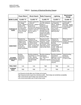
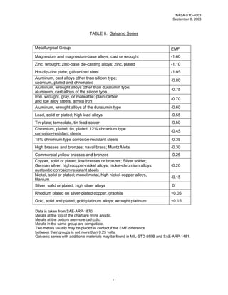
This document provides standards for electrical bonding on NASA launch vehicles, spacecraft, payloads, and flight equipment. It establishes requirements for power current return paths, shock and fault protection, electromagnetic interference protection, lightning protection, and electrostatic discharge protection. The document defines bonding classes and provides detailed requirements for bonding methods, surface cleaning and finishing, protection against galvanic corrosion, and special considerations for items like tubing, hoses, and multilayer insulation.
The document summarizes deviations between JScript and ECMAScript Edition 3. It discusses 22 specific deviations across areas like white space handling, future reserved words, string literals, the arguments object, global object handling, and more. For each deviation, it provides an example and the output from running the example on different browsers to illustrate differences in implementation. The goal is to document JScript's non-conformance to the ECMA specification for various language features.
This document presents the design and testing of several prototypes for a switching power amplifier intended to drive piezoelectric transducers. The initial through-hole prototype achieved the power and frequency specifications but had low efficiency. Revision 2 improved efficiency but failed due to heat issues. Revision 3 addressed this with a thermally enhanced design, achieving the highest efficiency. An isolated gate driver was also developed to allow testing higher voltages safely. Overall the work progressed from non-isolated to isolated amplifier designs with improvements in efficiency, voltage handling, and reliability at each stage.
This document provides reference documentation for Castor 1.3.1, an XML data binding framework. It allows converting Java objects to and from XML. The framework consists of marshalling and unmarshalling classes to handle the conversion. It can operate in introspection, mapping, or descriptor mode depending on the configuration provided. Introspection mode requires no configuration but uses default naming rules. Mapping mode uses a user-defined mapping file to customize the mapping. Descriptor mode generates descriptor classes to define the mapping.
This document is the ASME B30.2-2001 safety standard for overhead and gantry cranes. It provides definitions, requirements, and guidelines related to the construction, installation, inspection, testing, maintenance, and operation of overhead and gantry cranes. The standard addresses topics such as crane markings, clearances, construction requirements, electrical systems, hoisting equipment, inspections, qualifications for operators, load handling procedures, and lockout/tagout procedures. The document establishes mandatory safety rules and advisory guidelines to help ensure the safe design, operation and maintenance of overhead and gantry cranes.
This document provides information on industry process and automation solutions for potentially explosive environments. It discusses the ATEX directives for explosive atmospheres and defines equipment categories and groups. The document focuses on Bonfiglioli's series of bevel helical gear units that are certified for use in explosive environments. It provides details on the construction, ordering, mounting, lubrication, loads, dimensions, and declarations of conformity for the ATEX-specified gear units across various power ratings. Motor combinations for the gear units are also covered.
This document provides installation and operation instructions for a VVVF controller for elevators. It includes sections on safety tips, technical specifications, installation, commissioning, and error messages. The controller connects an elevator motor to the power supply and uses variable voltage and frequency control. It has inputs and outputs to interface with elevator shaft components and safety systems. Proper grounding, ventilation, and motor protection are emphasized for safe installation and operation.
This document is the user guide for the BlackBerry Curve 8520 smartphone. It provides instructions and shortcuts for the phone's basic functions like making calls, managing contacts, sending messages, browsing the internet, and using the camera. The guide also includes sections on voice commands, conference calls, call logs, call forwarding/blocking, and accessing voicemail. Troubleshooting tips are provided at the end.
The document provides an overview of engineering prints and drawings, including:
- The typical components of drawings such as the title block, grid system, and revision block.
- The main categories of drawings like piping and instrumentation diagrams, electrical schematics, and fabrication drawings.
- Views and perspectives commonly used in drawings such as orthographic, isometric, and exploded views.
This document is a user manual for CourseLab 2.3 that describes how to create and publish e-learning courses. It explains the structure of e-learning courses, which are composed of learning modules and chapters. Learning modules contain slides and frames. The manual provides instructions for setting up a new course by adding modules, slides, text, images and other objects. It also covers publishing courses and setting module and course runtime settings.
This document is the user manual for DEFORM 3D Version 6.0, a software for analyzing manufacturing processes. It provides an overview of DEFORM's capabilities for simulating metal forming processes, as well as descriptions of the pre-processor for setting up simulations, defining objects and materials, generating meshes, and applying boundary and initial conditions. It also covers using the post-processor to view results and running simulations in interactive or batch modes.
This document is a final design report for the wing structure of a Piper Cherokee aircraft. It includes load analysis of the aircraft's maneuvering, gust, and combined flight envelopes. Structural analysis was performed using a panel method in MATLAB to determine stresses, buckling, and factor of safety. Material selection, aeroelastic considerations, optimization, and finite element analysis are also discussed. The designed wing structure was found to be acceptable for the aircraft.
This document is the PostgreSQL 8.4.0 Documentation created by the PostgreSQL Global Development Group. It is covered by the license of the University of California and provides documentation for using PostgreSQL, including tutorials on basic and advanced features like installing PostgreSQL, creating and querying databases and tables, using SQL, and features like views, foreign keys, transactions, and inheritance. The documentation includes information on the history and development of PostgreSQL.
This is complete report you will require to make Export Import Report for India's Global Trade.. Pls give your likes and comments.. and pass on this to others..
This report summarizes the design of a wing for a low-speed utility aircraft based on a Lancair Legacy RG-550. The analysis utilized a NACA 2412 airfoil profile with spars and stringers placed within. Aerodynamic coefficients were determined using XFLR5 simulations. Loads were calculated based on FAR and aircraft specifications and used to analyze stresses, buckling, fracture, and fatigue. Failure modes were compared to a Von Mises criterion. Stresses were optimized using Monte Carlo methods to minimize weight while ensuring structural integrity. Finite element analysis in COMSOL supported the results. Key analyses included determining the centroid, area moments of inertia, lift distribution, stresses, and limited flight envelope.
This chapter reviews basic concepts such as sources, signals, amplifiers, transfer functions, and Bode plots. It discusses topics like noise, distortion, and the difference between large and small signals. The chapter also provides an overview of Fourier series which can be used to represent periodic signals as a sum of sine and cosine harmonics.
This document provides guidelines for fabricators and erectors on welded steel construction. It summarizes various welding processes such as shielded metal arc welding (SMAW), flux-cored arc welding (FCAW), submerged arc welding (SAW), and gas metal arc welding (GMAW). It emphasizes the importance of following welding codes and standards to ensure high quality and safety. The responsibilities of different parties in the construction process are also outlined.
This document provides an overview of the NX 9.0 software for engineering design. It covers topics such as getting started in NX 9.0, the user interface, modeling tools like form features and sketching, drafting, and assembly modeling. The document contains 8 chapters that describe these various aspects of NX 9.0 through examples and exercises for creating models of different mechanical components and assemblies.
This technical specification provides guidelines for the design, installation, testing and maintenance of main earthing systems in substations. It covers the function and features of earthing systems, safety criteria to protect against electric shock, design considerations such as soil resistivity and fault currents, installation of conductors and electrodes, testing of the system, and maintenance. The document aims to help engineers properly earth metalwork at substations to ensure safety and reliability of supply.
This document provides the table of contents for a training manual on Keycloak. The table of contents lists 17 chapters that cover topics like using Keycloak SPIs, debugging Keycloak, configuring logging, multifactor authentication, user federation, authentication flows, OpenID Connect, UMA, and examples of using offline tokens. It provides an overview of the content included in the training manual.
This document provides an overview of Keycloak and discusses how to set up and use Keycloak for identity and access management. It covers Keycloak concepts, installation, configuration of realms and clients, integration with applications, and examples of OAuth 2.0, OpenID Connect, and SAML usage with Keycloak. Debugging and analyzing Keycloak implementations is also demonstrated.
Joomla tutorials to install and customize BT Magazine Template version 1.0, J...US Blogger
Joomla tutorials to install and customize BT Magazine Template version 1.0, Joomla 3.X including information of features any ways to customize content component, interface and upgrade of free responsive BT Magazine from BowThemes.com.
BT Magazine is free responsive Joomla template for magazine, news and technology sites in 6 colors.
This document is the Asterisk Administrator Guide, which provides information on installing, configuring, and managing the Asterisk PBX system. It covers topics such as installing Asterisk from packages or source code, configuring channels and drivers, creating dialplans, and using the Asterisk Extension Language (AEL) for advanced dialplan functionality. The guide is intended for system administrators tasked with deploying and maintaining Asterisk installations.
This chapter introduces the Arduino project and the structure of the book. It discusses the success of the Arduino, which is attributed to its low cost, easy to use open source software programming interface, and the large community support through software libraries and online projects. However, the many online projects can lack detailed explanations and a common connecting theme, potentially causing confusion for beginners. The book aims to address this by providing a structured introduction to Arduino concepts through examples and explanations of theoretical foundations.
This whitepaper provides an introduction to Embarcadero C++Builder 2010. It discusses the key features and benefits of the integrated development environment, including the visual designer, debugger, compiler support for C++0x features, and integration of the Boost libraries. It also covers creating different application types like console and GUI apps, working with the Visual Component Library, and developing database applications using data access technologies like BDE, ADO, and dbExpress.
The document discusses the development of NASA's Space Launch System (SLS) heavy-lift launch vehicle. It provides a timeline of studies and milestones from 2010 to 2011 related to SLS, including establishing requirements, conducting design reviews, and setting a goal to achieve core operational capability by December 31, 2016. It also outlines NASA's strategy to develop exploration capabilities through SLS and other elements in a progressive, incremental manner to enable missions to the Moon, asteroids, and eventually Mars.
On future missions, Orion will launch on NASA’s Space Launch System (SLS) heavy-lift rocket currently being developed at the agency’s Marshall Space Flight Center in Huntsville, Alabama. A 70 metric-ton (77 ton) SLS will send Orion to a distant retrograde orbit around the moon on Exploration Mission-1 in the first test of the fully integrated Orion and SLS system.
The document discusses NASA's Space Launch System (SLS) heavy-lift launch vehicle. It describes the three proposed variations of the SLS (Block 1, 1B, and 2) with increasing payload capacity. Key specifications of the SLS include a diameter of 8.4 meters and use of cryogenic engines left over from the Space Shuttle program. The SLS will use two solid rocket boosters and the Orion Multi-Purpose Crew Vehicle to carry astronauts beyond low Earth orbit.
NASA and AARP celebrate 50 years of space exploration achievements including inspiring future generations, creating new jobs and technologies, and increasing discovery and knowledge of Earth and space. Key events include President Kennedy's 1962 speech advocating for space exploration, the 1969 Apollo 11 mission that landed the first humans on the Moon, and ongoing work at the International Space Station to enable future exploration.
The NASA Vision Workbench: Reflections on Image Processing in C++Matt Hancher
Slides that accompanied a discussion of the NASA Vision Workbech, an open-source C++ image processing library developed by the Intelligent Robotics Group at the NASA Ames Research Center.
Students will spend 6 days at the U.S. Space and Rocket Center in Huntsville, Alabama participating in educational activities about space exploration. The camp will include simulated space exploration exercises, building and launching rockets, and choosing one of three tracks in space, aviation, or robotics. The curriculum is designed to balance education with fun while encouraging innovation, teamwork, and exposure to challenges faced by NASA. Upon completion, students will receive a certificate from a high-ranking NASA official.
This technical report summarizes the results of the mineral resource estimate for the Agata North Nickel Laterite Project in the Philippines. Drilling between 2007-2008 consisted of 408 drill holes totaling over 7,300 meters. This defined limonite and saprolite zones containing nickel mineralization. Statistical and geological analysis of assay data supported creating block models for each zone. The limonite zone has over 1% nickel and the saprolite zone has slightly higher nickel contents. Based on the drill data, the mineral resource is estimated to be 41.5 million tonnes in the indicated category and 5.7 million tonnes in the inferred category, containing a total of approximately 150,000 tonnes of nickel.
This document provides a user's guide for AERMAP, which is a terrain preprocessor for the AERMOD dispersion model. It describes the basic concepts and components of AERMAP, provides details on its input and output formats, and explains how to run the model. The guide includes examples of AERMAP input files and describes how AERMAP processes digital elevation data to determine source and receptor elevations for use in air quality simulations.
This dissertation discusses observations of terrestrial gamma flashes (TGFs) made by the TETRA and LAGO detectors between 2010 and 2014. Chapter 1 provides an introduction to the topic. Chapter 2 discusses the motivation for studying TGFs. Chapter 3 describes the TETRA detector and its configuration. Chapter 4 presents an analysis of TGF event candidates detected by TETRA between 2010 and 2013, identifying 24 candidate events. Chapter 5 provides an updated analysis through 2014, identifying 28 candidate events. Chapter 6 analyzes the thunderstorm conditions associated with several TGF events. Chapter 7 describes the LAGO detector. Chapter 8 discusses plans for a next-generation TETRA detector. The dissertation concludes in Chapter 9.
This document provides standards for prequalified connections used in special and intermediate steel moment frames for seismic applications. It summarizes American National Standard ANSI/AISC 358-16, which establishes design requirements, material specifications, quality control procedures, and prequalification limits for several types of moment connections commonly used in seismic steel frames. The standard supersedes previous versions and incorporates two additional prequalified moment connection types.
This document provides an overview of impedance measurement techniques. It discusses impedance measurement basics, including component models and dependency factors. It also describes impedance measurement instruments and their operating theories for low frequency (LF) and radio frequency (RF) measurements. Additionally, it covers topics such as terminal configurations, fixtures, cabling, calibration techniques, compensation methods, and sources of measurement error. The document serves as a guide for impedance measurement technology and techniques.
This document provides guidance on navigation systems, equipment, and aids for naval ships. It outlines the organization of the chapter and describes general requirements for navigation systems including administration, maintenance, parts, installation, records, and safety precautions. It also describes specific non-electronic navigation aids such as magnetic compasses, timepieces including chronometers, and clocks.
The document is a master's thesis that describes the development of an integrated underwater acoustic localization and communication modem. A line array transducer was designed and built using piezoelectric elements to enable beamforming capabilities. Algorithms for localization using time difference of arrival and time of arrival were implemented. Digital phase shift keying modulation was used for communication. The modem was tested in a pool environment and showed the ability to localize, communicate, and mitigate echoes through beamforming, although echoes still impacted performance.
This document is the thesis abstract for a master's degree in engineering robotics. It summarizes the development of an integrated underwater acoustic localization and communication modem. A line array transducer was designed and built using piezoelectric elements to enable beamforming for directed transmission and reception. Localization was implemented using time difference of arrival and time of arrival measurements to estimate bearing and range. Digital phase shift keying modulation was used for communication. The modem was tested in a pool, where echo was found to significantly impact performance in some cases. The work included hardware, algorithms for localization and communication, and testing of the integrated system.
This document provides an introduction to Unigraphics NX3 software. It discusses the product realization process involving design and manufacturing. A brief history of CAD/CAM development is also provided, noting the evolution from early computer-aided drafting to today's integrated CAD/CAM/CAE systems. The document scopes the tutorial, which will cover topics like modeling, assembly, drafting, machining and finite element analysis in Unigraphics NX3.
This doctoral dissertation investigates the superconducting proximity effect in InAs nanowires. The first experiment observes tunneling resonances of Andreev bound states in a proximitized InAs quantum dot in the Kondo regime. An additional zero-bias peak of unknown origin is also observed. The second experiment applies an external magnetic field, revealing spin-resolved Andreev bound states in another proximitized InAs quantum dot. From the splitting of tunneling resonances, g-factors of 5 and 10 are extracted in two different devices. The third experiment compares the induced gaps of epitaxial core-shell InAs-Al nanowires with control devices using evaporated Al films. The epitaxial nanowires
This thesis examines wind speeds over the British Isles using a high-resolution atmospheric model to produce a new wind speed dataset covering the region from 2000 to 2010 at 3km resolution. The author validates the model results against observations from various sources, including meteorological stations, buoys, offshore platforms, and satellites. The ability of the dataset to predict power outputs from current wind farms is demonstrated, and patterns of future wind production are compared to electricity demand patterns to assess the ability of wind generation to meet demand.
This thesis examines drag estimates for the Air Force Research Laboratory's (AFRL) joined-wing sensor craft using three methods: the Roskam method, the Roskam/AVTIE strip method, and the Roskam/AVTIE pan air method. The Roskam/AVTIE pan air method, which uses XFOIL to measure parasite drag effects, was determined to be the ideal approach. While performance parameters had previously been estimated using constant lift-to-drag assumptions, this research provides the first detailed drag estimates for the AFRL configuration.
This document is a project report on the design of a multi-band rejection electromagnetic interference (EMI) shield using a frequency selective surface. It includes an abstract, table of contents, introduction on EMI and EMI shielding materials and techniques. It also provides background on frequency selective surfaces including their history, design principles, common element geometries and applications. The report was submitted by four students for their BTech final year project and approved by their supervisor and head of department. It details the design, simulation and fabrication of an ultra-thin, flexible EMI shield capable of rejecting multiple unwanted frequencies using a frequency selective surface approach.
This document is a report that analyzes replacing regular transmission line conductors with superconductors. It discusses the problems with current transmission lines, such as losses due to resistance, instability, and environmental/safety issues. The report proposes using superconducting cables cooled by liquid hydrogen in underground conduits as a solution. It evaluates the feasibility and costs/benefits of implementing this system compared to alternatives. The conclusion recommends superconducting cables as they would eliminate losses and provide a more efficient, reliable and environmentally friendly grid.
Electrical power supply and distributionSouvik Dutta
This document is a technical manual that provides guidance on electrical power supply and distribution systems for the Army and Air Force. It covers topics such as voltage selection, main electric supply stations/substations, aerial and underground distribution lines. The manual establishes standards and procedures for designing, evaluating, and selecting electrical power systems to ensure reliable and efficient power delivery to military installations.
Studies on Metal-Dielectric Plasmonic.PDFssuser5a406f
This chapter provides an introduction to plasmonics and plasmonic structures. It discusses the Drude and Drude-Lorentz models used to describe the optical properties of metals. Surface plasmon resonance is explained, where collective oscillations of free electrons at a metal-dielectric interface can be excited by incident light under the plasmon resonance condition. Key concepts introduced include surface plasmon polaritons and the dispersion relationship between plasmon wavelength and wavevector.
This document provides operation and maintenance instructions for a DVOR 432 navigation system. It includes sections on general information, installation, operation, alignment procedures, maintenance, and fault location/repairs. The installation section describes selecting an installation site, installing foundations and shelters, mounting antennas, cabling, and rack installation including power, RF/AF connections, and external interfaces. Safety precautions and required tools/materials are also outlined.
This document provides installation instructions for a single-shelf high-density fiber optic frame housing manufactured by Corning. It describes the components, necessary tools, safety precautions, and step-by-step procedures for unpacking, rack mounting, cable preparation, fiber routing, splicing, documentation and maintenance of the fiber optic system. The procedures include rack mounting the housing, preparing cables by removing sheaths and terminating fibers, routing and splicing fibers, installing connectors, strain reliefs and grounding cables.
151 south africa cap bank-protection-baker-duly-2008wmelis
This document provides an introduction to reactive power compensation using shunt capacitor banks and discusses their application. It explains that electrical systems are inherently inductive and require capacitive reactive power to improve transmission capacity and reduce losses. Shunt capacitor banks provide this capacitive reactive power and are used to correct the power factor towards unity. The document discusses factors to consider when determining the optimal location for a shunt capacitor bank installation, such as maintaining voltage profiles and reducing losses along feeder circuits. Location options include at the supply point to improve the overall power factor or distributed at load points to offset inductance directly.
HCL Notes und Domino Lizenzkostenreduzierung in der Welt von DLAUpanagenda
Webinar Recording: https://www.panagenda.com/webinars/hcl-notes-und-domino-lizenzkostenreduzierung-in-der-welt-von-dlau/
DLAU und die Lizenzen nach dem CCB- und CCX-Modell sind für viele in der HCL-Community seit letztem Jahr ein heißes Thema. Als Notes- oder Domino-Kunde haben Sie vielleicht mit unerwartet hohen Benutzerzahlen und Lizenzgebühren zu kämpfen. Sie fragen sich vielleicht, wie diese neue Art der Lizenzierung funktioniert und welchen Nutzen sie Ihnen bringt. Vor allem wollen Sie sicherlich Ihr Budget einhalten und Kosten sparen, wo immer möglich. Das verstehen wir und wir möchten Ihnen dabei helfen!
Wir erklären Ihnen, wie Sie häufige Konfigurationsprobleme lösen können, die dazu führen können, dass mehr Benutzer gezählt werden als nötig, und wie Sie überflüssige oder ungenutzte Konten identifizieren und entfernen können, um Geld zu sparen. Es gibt auch einige Ansätze, die zu unnötigen Ausgaben führen können, z. B. wenn ein Personendokument anstelle eines Mail-Ins für geteilte Mailboxen verwendet wird. Wir zeigen Ihnen solche Fälle und deren Lösungen. Und natürlich erklären wir Ihnen das neue Lizenzmodell.
Nehmen Sie an diesem Webinar teil, bei dem HCL-Ambassador Marc Thomas und Gastredner Franz Walder Ihnen diese neue Welt näherbringen. Es vermittelt Ihnen die Tools und das Know-how, um den Überblick zu bewahren. Sie werden in der Lage sein, Ihre Kosten durch eine optimierte Domino-Konfiguration zu reduzieren und auch in Zukunft gering zu halten.
Diese Themen werden behandelt
- Reduzierung der Lizenzkosten durch Auffinden und Beheben von Fehlkonfigurationen und überflüssigen Konten
- Wie funktionieren CCB- und CCX-Lizenzen wirklich?
- Verstehen des DLAU-Tools und wie man es am besten nutzt
- Tipps für häufige Problembereiche, wie z. B. Team-Postfächer, Funktions-/Testbenutzer usw.
- Praxisbeispiele und Best Practices zum sofortigen Umsetzen
HCL Notes and Domino License Cost Reduction in the World of DLAUpanagenda
Webinar Recording: https://www.panagenda.com/webinars/hcl-notes-and-domino-license-cost-reduction-in-the-world-of-dlau/
The introduction of DLAU and the CCB & CCX licensing model caused quite a stir in the HCL community. As a Notes and Domino customer, you may have faced challenges with unexpected user counts and license costs. You probably have questions on how this new licensing approach works and how to benefit from it. Most importantly, you likely have budget constraints and want to save money where possible. Don’t worry, we can help with all of this!
We’ll show you how to fix common misconfigurations that cause higher-than-expected user counts, and how to identify accounts which you can deactivate to save money. There are also frequent patterns that can cause unnecessary cost, like using a person document instead of a mail-in for shared mailboxes. We’ll provide examples and solutions for those as well. And naturally we’ll explain the new licensing model.
Join HCL Ambassador Marc Thomas in this webinar with a special guest appearance from Franz Walder. It will give you the tools and know-how to stay on top of what is going on with Domino licensing. You will be able lower your cost through an optimized configuration and keep it low going forward.
These topics will be covered
- Reducing license cost by finding and fixing misconfigurations and superfluous accounts
- How do CCB and CCX licenses really work?
- Understanding the DLAU tool and how to best utilize it
- Tips for common problem areas, like team mailboxes, functional/test users, etc
- Practical examples and best practices to implement right away
Taking AI to the Next Level in Manufacturing.pdfssuserfac0301
Read Taking AI to the Next Level in Manufacturing to gain insights on AI adoption in the manufacturing industry, such as:
1. How quickly AI is being implemented in manufacturing.
2. Which barriers stand in the way of AI adoption.
3. How data quality and governance form the backbone of AI.
4. Organizational processes and structures that may inhibit effective AI adoption.
6. Ideas and approaches to help build your organization's AI strategy.
Unlock the Future of Search with MongoDB Atlas_ Vector Search Unleashed.pdfMalak Abu Hammad
Discover how MongoDB Atlas and vector search technology can revolutionize your application's search capabilities. This comprehensive presentation covers:
* What is Vector Search?
* Importance and benefits of vector search
* Practical use cases across various industries
* Step-by-step implementation guide
* Live demos with code snippets
* Enhancing LLM capabilities with vector search
* Best practices and optimization strategies
Perfect for developers, AI enthusiasts, and tech leaders. Learn how to leverage MongoDB Atlas to deliver highly relevant, context-aware search results, transforming your data retrieval process. Stay ahead in tech innovation and maximize the potential of your applications.
#MongoDB #VectorSearch #AI #SemanticSearch #TechInnovation #DataScience #LLM #MachineLearning #SearchTechnology
Ocean lotus Threat actors project by John Sitima 2024 (1).pptxSitimaJohn
Ocean Lotus cyber threat actors represent a sophisticated, persistent, and politically motivated group that poses a significant risk to organizations and individuals in the Southeast Asian region. Their continuous evolution and adaptability underscore the need for robust cybersecurity measures and international cooperation to identify and mitigate the threats posed by such advanced persistent threat groups.
GraphRAG for Life Science to increase LLM accuracyTomaz Bratanic
GraphRAG for life science domain, where you retriever information from biomedical knowledge graphs using LLMs to increase the accuracy and performance of generated answers
In his public lecture, Christian Timmerer provides insights into the fascinating history of video streaming, starting from its humble beginnings before YouTube to the groundbreaking technologies that now dominate platforms like Netflix and ORF ON. Timmerer also presents provocative contributions of his own that have significantly influenced the industry. He concludes by looking at future challenges and invites the audience to join in a discussion.
AI 101: An Introduction to the Basics and Impact of Artificial IntelligenceIndexBug
Imagine a world where machines not only perform tasks but also learn, adapt, and make decisions. This is the promise of Artificial Intelligence (AI), a technology that's not just enhancing our lives but revolutionizing entire industries.
Have you ever been confused by the myriad of choices offered by AWS for hosting a website or an API?
Lambda, Elastic Beanstalk, Lightsail, Amplify, S3 (and more!) can each host websites + APIs. But which one should we choose?
Which one is cheapest? Which one is fastest? Which one will scale to meet our needs?
Join me in this session as we dive into each AWS hosting service to determine which one is best for your scenario and explain why!
UiPath Test Automation using UiPath Test Suite series, part 6DianaGray10
Welcome to UiPath Test Automation using UiPath Test Suite series part 6. In this session, we will cover Test Automation with generative AI and Open AI.
UiPath Test Automation with generative AI and Open AI webinar offers an in-depth exploration of leveraging cutting-edge technologies for test automation within the UiPath platform. Attendees will delve into the integration of generative AI, a test automation solution, with Open AI advanced natural language processing capabilities.
Throughout the session, participants will discover how this synergy empowers testers to automate repetitive tasks, enhance testing accuracy, and expedite the software testing life cycle. Topics covered include the seamless integration process, practical use cases, and the benefits of harnessing AI-driven automation for UiPath testing initiatives. By attending this webinar, testers, and automation professionals can gain valuable insights into harnessing the power of AI to optimize their test automation workflows within the UiPath ecosystem, ultimately driving efficiency and quality in software development processes.
What will you get from this session?
1. Insights into integrating generative AI.
2. Understanding how this integration enhances test automation within the UiPath platform
3. Practical demonstrations
4. Exploration of real-world use cases illustrating the benefits of AI-driven test automation for UiPath
Topics covered:
What is generative AI
Test Automation with generative AI and Open AI.
UiPath integration with generative AI
Speaker:
Deepak Rai, Automation Practice Lead, Boundaryless Group and UiPath MVP
TrustArc Webinar - 2024 Global Privacy SurveyTrustArc
How does your privacy program stack up against your peers? What challenges are privacy teams tackling and prioritizing in 2024?
In the fifth annual Global Privacy Benchmarks Survey, we asked over 1,800 global privacy professionals and business executives to share their perspectives on the current state of privacy inside and outside of their organizations. This year’s report focused on emerging areas of importance for privacy and compliance professionals, including considerations and implications of Artificial Intelligence (AI) technologies, building brand trust, and different approaches for achieving higher privacy competence scores.
See how organizational priorities and strategic approaches to data security and privacy are evolving around the globe.
This webinar will review:
- The top 10 privacy insights from the fifth annual Global Privacy Benchmarks Survey
- The top challenges for privacy leaders, practitioners, and organizations in 2024
- Key themes to consider in developing and maintaining your privacy program
Generating privacy-protected synthetic data using Secludy and MilvusZilliz
During this demo, the founders of Secludy will demonstrate how their system utilizes Milvus to store and manipulate embeddings for generating privacy-protected synthetic data. Their approach not only maintains the confidentiality of the original data but also enhances the utility and scalability of LLMs under privacy constraints. Attendees, including machine learning engineers, data scientists, and data managers, will witness first-hand how Secludy's integration with Milvus empowers organizations to harness the power of LLMs securely and efficiently.
Climate Impact of Software Testing at Nordic Testing DaysKari Kakkonen
My slides at Nordic Testing Days 6.6.2024
Climate impact / sustainability of software testing discussed on the talk. ICT and testing must carry their part of global responsibility to help with the climat warming. We can minimize the carbon footprint but we can also have a carbon handprint, a positive impact on the climate. Quality characteristics can be added with sustainability, and then measured continuously. Test environments can be used less, and in smaller scale and on demand. Test techniques can be used in optimizing or minimizing number of tests. Test automation can be used to speed up testing.
Monitoring and Managing Anomaly Detection on OpenShift.pdfTosin Akinosho
Monitoring and Managing Anomaly Detection on OpenShift
Overview
Dive into the world of anomaly detection on edge devices with our comprehensive hands-on tutorial. This SlideShare presentation will guide you through the entire process, from data collection and model training to edge deployment and real-time monitoring. Perfect for those looking to implement robust anomaly detection systems on resource-constrained IoT/edge devices.
Key Topics Covered
1. Introduction to Anomaly Detection
- Understand the fundamentals of anomaly detection and its importance in identifying unusual behavior or failures in systems.
2. Understanding Edge (IoT)
- Learn about edge computing and IoT, and how they enable real-time data processing and decision-making at the source.
3. What is ArgoCD?
- Discover ArgoCD, a declarative, GitOps continuous delivery tool for Kubernetes, and its role in deploying applications on edge devices.
4. Deployment Using ArgoCD for Edge Devices
- Step-by-step guide on deploying anomaly detection models on edge devices using ArgoCD.
5. Introduction to Apache Kafka and S3
- Explore Apache Kafka for real-time data streaming and Amazon S3 for scalable storage solutions.
6. Viewing Kafka Messages in the Data Lake
- Learn how to view and analyze Kafka messages stored in a data lake for better insights.
7. What is Prometheus?
- Get to know Prometheus, an open-source monitoring and alerting toolkit, and its application in monitoring edge devices.
8. Monitoring Application Metrics with Prometheus
- Detailed instructions on setting up Prometheus to monitor the performance and health of your anomaly detection system.
9. What is Camel K?
- Introduction to Camel K, a lightweight integration framework built on Apache Camel, designed for Kubernetes.
10. Configuring Camel K Integrations for Data Pipelines
- Learn how to configure Camel K for seamless data pipeline integrations in your anomaly detection workflow.
11. What is a Jupyter Notebook?
- Overview of Jupyter Notebooks, an open-source web application for creating and sharing documents with live code, equations, visualizations, and narrative text.
12. Jupyter Notebooks with Code Examples
- Hands-on examples and code snippets in Jupyter Notebooks to help you implement and test anomaly detection models.
Programming Foundation Models with DSPy - Meetup SlidesZilliz
Prompting language models is hard, while programming language models is easy. In this talk, I will discuss the state-of-the-art framework DSPy for programming foundation models with its powerful optimizers and runtime constraint system.
Programming Foundation Models with DSPy - Meetup Slides
Nasa std-4003
1. METRIC/
INCH-POUND
National Aeronautics and NASA-STD-4003
Space Administration
SEPTEMBER 8, 2003
ELECTRICAL BONDING FOR
NASA LAUNCH VEHICLES, SPACECRAFT,
PAYLOADS, AND FLIGHT EQUIPMENT
NASA TECHNICAL STANDARD
Approved for Public Release – Distribution is Unlimited
2.
3. NASA-STD-4003
September 8, 2003
DOCUMENT HISTORY LOG, NASA-STD-4003
Status
(Baseline/ Document Effective
Description
Revision/ Revision Date
Canceled)
Baseline 9-08-2003 Baseline Release
i
5. NASA-STD-4003
September 8, 2003
FOREWORD
This standard is approved for use by NASA Headquarters and all NASA Centers and provides a
common framework for consistent electrical bonding practices across NASA programs.
The intent of this NASA standard is to provide stand-alone requirements and to provide enough
data to help modify requirements or to allow waivers if needed.
Requests for information, corrections, or additions to this standard should be directed to the
Electromagnetic Environmental Effects Team, ED44/4708, MSFC, AL 35812. Requests for
general information concerning NASA Technical Standards should be sent to the NASA
Technical Program Standards Office, ED41 MSFC, AL 35812, (telephone 256-544-2448). This
and other NASA standards may be viewed and downloaded, free-of-charge, from our NASA
Standards Homepage: http://standards.nasa.gov.
Original Signed By
Theron M. Bradley, Jr.
NASA Chief Engineer
iii
7. NASA-STD-4003
September 8, 2003
TABLE OF CONTENTS
PARAGRAPH PAGE
DOCUMENT HISTORY LOG ...................................................................................i
FOREWORD ..................................................................................................... iii
TABLE OF CONTENTS .................................................................................... v
LIST OF FIGURES,........................................................................................... vi
LIST OF TABLES .............................................................................................. vi
1. SCOPE ............................................................................................................ 1
1.1 Scope .......................................................................................................... 1
1.2 Purpose ....................................................................................................... 1
1.3 Applicability ................................................................................................. 1
2. DOCUMENTS ................................................................................................... 1
2.1 Applicable Documents................................................................................. 1
2.2 Referenced Documents............................................................................... 1
2.3 Order of Precedence ................................................................................... 2
3. DEFINITIONS AND ACRONYMS ..................................................................... 2
4. GENERAL REQUIREMENTS ........................................................................... 3
4.1 Power Current Return Path (Class C) ......................................................... 3
4.1.1 Hazardous Area Bonding ................................................................... 3
4.2 Shock and Fault Protection (Class H) ......................................................... 5
4.2.1 Hazardous Area Bonding ...................................................................... 5
4.3 Electromagnetic Interference or Radio Frequency (Class R) ...................... 5
4.3.1 Electrical Connectors............................................................................. 5
4.3.2 Antennas ............................................................................................... 5
4.3.3 Bond Straps........................................................................................... 5
4.4 Lightning Protection (Class L) ..................................................................... 7
4.4.1 Hazardous Area Bonding ...................................................................... 7
4.4.2 Conductivity of Bond Joint ..................................................................... 7
4.4.3 Bond Straps........................................................................................... 7
4.5 Electrostatic Discharge (Class S)................................................................ 7
4.5.1 Multilayer Insulation............................................................................... 8
4.5.2 Hazardous Area Bonding ...................................................................... 8
4.5.3 Pipe, Tubing, and Hoses ....................................................................... 8
4.5.4 Nonmetallic Plumbing............................................................................ 8
5. DETAILED REQUIREMENTS ........................................................................... 8
5.1 Bonding Methods ........................................................................................ 8
5.1.1 Bond Straps........................................................................................... 9
5.2 Surface Cleaning and Finishing .................................................................. 9
5.2.1 Aluminum............................................................................................... 9
5.2.2 Magnesium ............................................................................................ 9
5.2.3 Steel ...................................................................................................... 9
v
8. NASA-STD-4003
September 8, 2003
TABLE OF CONTENTS (CONT’D)
PARAGRAPH PAGE
5.2.4 Protection of Treated Surfaces.............................................................. 9
5.3 Galvanic Corrosion of Dissimilar Metals...................................................... 9
5.4 Special Considerations................................................................................ 10
5.4.1 Tubing and Hoses ................................................................................. 10
5.4.2 Graphite Fiber Reinforced Plastic.......................................................... 10
5.4.3 Multilayer Insulation............................................................................... 10
5.5 Verification................................................................................................... 12
6. GUIDELINES..................................................................................................... 12
6.1 Design Requirements .................................................................................. 12
6.2 Power Current Return Path (Class C) ......................................................... 12
6.3 Shock and Fault Protection (Class H) ......................................................... 12
6.4 Electromagnetic Interference or Radio Frequency (Class R) ...................... 13
6.5 Lightning Protection (Class L) ..................................................................... 14
6.6 Electrostatic Discharge (Class S)................................................................ 15
6.7 Surface Cleaning and Finishing .................................................................. 15
6.8 Dissimilar Metals ......................................................................................... 16
6.9 Special Considerations................................................................................ 16
6.10 Verification................................................................................................... 17
LIST OF FIGURES
FIGURE PAGE
1. Fault Current vs. Maximum Bonding Resistance
In the Presence of Flammable Vapors or Liquids ............................................. 6
LIST OF TABLES
TABLE PAGE
I. Summary of Electrical Bonding Classes ........................................................... 4
II. Galvanic Series ................................................................................................. 11
vi
9. NASA-STD-4003
September 8, 2003
ELECTRICAL BONDING FOR NASA LAUNCH VEHICLES,
SPACECRAFT, PAYLOADS, AND FLIGHT EQUIPMENT
1. SCOPE
1.1 Scope. This standard defines the basic electrical bonding requirements for NASA
launch vehicles, spacecraft, payloads, and equipment.
1.2 Purpose. The intent of this standard is to provide fundamental aerospace electrical
bonding requirements. This standard classifies electrical bonds according to their purpose and
states the requirements for the various classes. The rationale for specific requirements is
stated where possible. Additional data is provided to support tailoring for new applications if
necessary.
1.3 Applicability. This Standard recommends engineering practices for NASA programs
and projects. It may be cited in contracts and program documents as a technical requirement or
as a reference for guidance. Determining the suitability of this Standard and its provisions is the
responsibility of program/project management and the performing organization. Individual
provisions of this standard may be tailored (i.e. modified or deleted) by contract or program
specifications to meet specific program/project needs and constraints.
2. DOCUMENTS
2.1 Applicable Documents. The documents in this paragraph are applicable to the
extent specified herein.
Mil-C-5541, Rev. E Military Specification, Chemical Conversion
11/30/1990 Coatings on Aluminum and Aluminum Alloys
SAE-AMS-M-3171 Magnesium Alloy, Processes for
4/01/1998 Pretreatment and Prevention of Corrosion on
SAE-ARP-5412 Aircraft Lightning Environment and Related
11/1/1999 Test Waveforms
2.2 Referenced Documents. The documents in this paragraph are for reference only.
MIL-STD-889 Military Standard, Dissimilar Metals
Rev. B
7/7/1976, change 3, 5/13/1993
NSTS 37330 Bonding, Electrical, and Lightning
12/2/1999 Specifications
SAE-ARP-1481 Corrosion Control and Electrical
Rev. A Conductivity in Enclosure Design
9/1/98
1
10. NASA-STD-4003
September 8, 2003
SAE-ARP-ILO1870 Aerospace Systems Electrical Bonding and
1/1/1987 (R91) Grounding for Electromagnetic Compatibility
and Safety
SSP 30245 Space Station Electrical Bonding
Rev. E, Requirements
10/15/1999
Radio Engineers’ Handbook F. E. Terman, McGraw Hill Book Co., Inc.,
New York and London, 1943
Lightning Protection of Aircraft, Fisher, Plumer, and Perala, LTI, Inc.,
Pittsfield, MA, 1990
2.3 Order of Precedence. Where this document is adopted or imposed by contract on a
program or project, the technical requirements of this document take precedence, in the case of
conflict, over the technical requirements cited in other referenced documents.
Program specific standards are already in effect for the space shuttle, as defined in NSTS
37330, and for the space station, as defined in SSP 30245.
3. DEFINITIONS AND ACRONYMS
λ Wavelength
µH Microhenries
ac Alternating current
AWG American Wire Gauge
CLASS “C” Class of bond for intentional current return
CLASS “H” Class of bond for fault current return
CLASS “L” Class of bond for lightning current
CLASS “R” Class of bond for radio frequency current
CLASS “S” Class of bond for dissipation of electrostatic charge
dB Decibels
dc Direct current
EED Electro-explosive device
EMF Electromotive force
ESD Electrostatic discharge
GFRP Graphite filament reinforced plastic
MHz Megahertz
NASA National Aeronautics and Space Administration
P-static Precipitation static due to impact of charged particles on antennas
Q The ratio of reactance to resistance in a tuned circuit
RF Radio frequency
2
11. NASA-STD-4003
September 8, 2003
4. GENERAL REQUIREMENTS
Electrical bonding is the process of providing good electrical connection across mechanical
interfaces to minimize electrical potential differences between equipment and individual parts of
structure. Good electrical bonding provides:
- Fault current paths for protection against fire and personnel shock
- A low impedance bond path for antenna installations to ensure no degradation of
acceptable performance and to protect the antenna element from damage caused by
P-static, RF currents, or lightning events
- Provides a current path for radio frequencies for proper operation of filters and
shields
- Provides protection against the effects of lightning
- A means to prevent or safely discharge static charges.
Electrical bonds are classified according to the purpose for the bond. There may be more than
one purpose for bonding a specific interface, and the bond shall meet the requirements of each
applicable class. Notes shall be provided on assembly drawings indicating the applicable class
or classes.
This section describes the various classes of electrical bonding. Each section contains the
general requirement, specific design requirements, and, in most cases, measurable resistance
values for each class of bond. Guidelines discuss the reasons for some of the requirements
and provide data for possible modifications or rationale for waivers to the requirements.
Table I gives a summary of the classes of bonds.
4.1 Power Current Return Path (Class C). Small satellite systems are occasionally
designed to allow dc power to be returned through structure. When this is the case, the total
voltage drop across all joints between the power supply and the load shall be controlled in order
to keep the voltage within the tolerance of the applicable power quality standard. If no power
quality standard is applicable, a default voltage drop value of 3.5% shall be used (one volt drop
for 28-volt systems and four volts for 120-volt systems). The voltage drop allowed divided by
the maximum current that may be delivered by the power supply will give the total resistance
allowed in the circuit. This resistance includes the wire, its connectors, and all bonded joints in
the structure return path. The resistance limit for each joint can then be allocated. Refer to
paragraph 6.2 for more information
The use of a dedicated power return wire will be required for most programs. Class “C” bonding
is only applicable for the few programs that use structure return.
Magnesium alloy structure shall not be used as an intentional current return path. The
temperature of a poor joint could rise to the ignition point of magnesium.
4.1.1 Hazardous Area Bonding. Structure with joints located in oxygen enriched areas
or where flammable vapors may occur shall not be used as the primary current return path. A
primary current return path shall be provided around the hazardous area to prevent arcs or hot
spots. The resistance limits of Figure 1 are applicable to Class “C” bonds in flammable
atmospheres as well as for fault current.
3
12. NASA-STD-4003
September 8, 2003
TABLE I. Summary of Electrical Bonding Classes
Electrostatic
Power Return Shock Hazard Radio Frequency Lightning
Charge
BOND CLASS CLASS "C" CLASS "H" CLASS "R" CLASS "L" CLASS "S"
Reduces power Protects against fire Protects equipment Protects equipment Protects against
and voltage or shock to from RF emissions. from lightning electrostatic
losses. Applies to personnel. Applies to Applies to effects. Applies to discharge. Applies
equipment & equipment & equipment that equipment or to any item subject
structure, which structure that may be could generate, structure that would to electrostatic
PURPOSE OF are required to required to carry fault retransmit, or be carry current charging.
BOND return intentional current in case of a susceptible to RF. resulting from a
current through short to case or Includes antenna lightning strike.
structure. structure. mounts and cable
shield connections.
Covers wide
frequency range.
Requires low Requires low Requires low RF Requires low Allows moderate
impedance & low impedance & low impedance at high impedance at impedance.
voltage across voltage across joints frequency. Direct moderate frequency. Jumpers and straps
joints to assure to prevent shock contact preferred. Bonding acceptable.
adequate power hazard or fire due to No jumpers. Short, components must
BOND REQT. to the user. short. Jumpers and wide strap may be withstand high
Jumpers and straps acceptable. used as last resort. current. Straps and
straps acceptable. jumpers must
withstand high
magnetic forces.
Bonding Bonding resistance Bonding resistance Bonding resistance Typical bonding
resistance requirement, 0.1 ohm requirement, requirement resistance
requirement or less. Special 2.5. milliohms or depends on current. requirement,
DC BOND
depends on requirements when less. Low 500 volts or less 1.0 ohm or less.
RESISTANCE
current. near flammable inductance required. across any joint.
REQT.
vapors. Low inductance
required.
FREQ. REQT. Low Low High High Low
CURRENT
High High Low High Low
REQT.
Low frequency bonds allow use of straps and jumpers.
High frequency bonds require low inductance paths. Short straps are sometimes acceptable.
High current bonds require large cross sectional areas.
Low current bonds allow use of small contact areas.
4
13. NASA-STD-4003
September 8, 2003
4.2 Shock and Fault Protection (Class H). Fault current, due to short circuits to
equipment case or structure, may cause shock or fire hazards. All electrically conductive
equipment cases that may develop potentials due to short circuits shall be electrically bonded to
structure. The bond shall minimize shock hazard voltages and allow proper operation of circuit
protection devices such as circuit breakers or fuses. Bonding of structural joints in the fault
current return path shall provide for the maximum current that may be delivered by the power
supply until the fuse or circuit breaker disconnects. For personnel and fire safety the fault
current return path shall be capable of conducting a minimum of 500% overload current for a
time period of 0.5 second. Typical personnel protection breakers will trip within 0.2 second after
a hard short to case. Resultant voltage on the enclosure of the affected component must not
exceed 4.5 volts, and no fire or damage to the bond is allowed.
Exposed cases or chassis of electrical or electronic equipment shall be bonded to structure with
a resistance of 0.1 ohm or less. Metallic conduit, cable trays, and other conductive objects
susceptible to short circuits shall have a resistance to structure of 0.1 ohm or less. Refer to
paragraph 6.3 for more information.
4.2.1 Hazardous Area Bonding. Electrical bonding of mating surfaces in areas where
explosive fuel or gas may be present shall be adequate to prevent ignition due to heating or
arcing. Resistance across each of these joints shall not exceed the maximum resistance values
shown in Figure 1.
4.3 Electromagnetic Interference or Radio Frequency (Class R). Basic structure and
vehicle skin shall be designed and constructed to provide a uniform low-impedance path at
radio frequencies so that system operational requirements are met. RF bonding is required
between all conductive basic structural components of the vehicle. The dc resistance across
each joint shall not exceed 2.5 milliohms.
All electrical and electronic equipment shall be installed to provide a continuous low impedance
path from the equipment enclosure to the structure. The dc resistance from equipment case to
structure shall not exceed 2.5 milliohms. The bond from the equipment enclosure to any
mounting plate furnished with the equipment shall not exceed 2.5 milliohms.
The path to structure and the joints in that path shall be designed such that the inductance and
overall impedance including resonances are low enough to prevent interference at the
frequencies of interest. The dc resistance across each joint in the path shall not exceed 2.5
milliohms. Refer to paragraph 6.4 for more information.
4.3.1 Electrical Connectors. Electrical connectors and their backshells that may be used
to terminate cable shields shall be installed to provide a low impedance path from the backshell
to the equipment case. The dc resistance from backshell to case shall not exceed 2.5
milliohms.
4.3.2 Antennas. Antennas that require low impedance to the ground plane for proper
operation shall be installed with low impedance to structure at the frequencies of interest. The
dc resistance from antenna mounting surface to structure shall not exceed 2.5 milliohms.
4.3.3 Bond Straps. Direct contact between mating surfaces is the preferred method for
electrical bonding. Bonding straps may be the only alternative where equipment is vibration or
thermally isolated. If straps are used, they shall be flat and have a length-to-width ratio of less
than 5 to 1 to minimize the inductance of the strap.
5
14. NASA-STD-4003
September 8, 2003
100
MAXIMUM RESISTANCE
(MILLIOHMS)
HAZARD RESISTANCE
10
(MILLIOHMS)
RESISTANCE (MILLIOHMS)
1
0.1
0.01
10 100 1000 10000
FAULT CURRENT (AMPS)
FAULT MAXIMUM HAZARD
CURRENT RESISTANCE RESISTANCE
(AMPS) (MILLIOHMS) (MILLIOHMS)
30 3.6 18
49 1.86 9.3
58 1.54 7.7
100 0.74 3.7
200 0.37 1.85
1000 0.074 0.37
5000 0.0148 0.074
FIGURE 1. Fault Current vs. Maximum Allowed Bonding Resistance in the Presence of
Flammable Vapors or Liquids
6
15. NASA-STD-4003
September 8, 2003
4.4 Lightning Protection (Class L). Protection against lightning strikes must be provided
for launch vehicles and their payloads during transportation, storage, prelaunch`, launch, and
landing. Propellant, pyrotechnics, and electronic equipment are particularly susceptible to direct
and indirect effects of lightning. A path shall be specifically designed for lightning current from
attach point(s) to exit point(s). The designed path shall provide the lowest impedance path for
lightning current between attach and exit points. The goal is to direct the lightning current away
from critical areas such as pyrotechnic devices, rocket motors, fuel, flush mounted antennae,
electronic equipment, and cables.
Each electrical bond shall have low resistance and adequate contact area to carry its share of
lightning current without burning, melting, or other heating effects from the long-duration, high-
current portion of the lightning strike. The bonds shall have low inductance to prevent arcing
and coupling of voltage spikes into electronic circuits due to the fast rise time portion of the
lightning strike.
Multiple rivets, bolts, or other fasteners shall be used at joints in vehicle skin and structure to
ensure multiple metallic contact areas capable of sharing lightning current. Doors, hatches, and
other apertures shall be bonded with multiple connections to minimize aperture size and slot
length. Minimizing aperture size reduces induced currents in underlying cables.
The lightning current waveforms defined in SAE-ARP-5412 shall be used for analysis to
determine design requirements of the bond. Refer to paragraph 6.5 for more information.
4.4.1 Hazardous Area Bonding. Fuel and pyrotechnics shall be completely enclosed by a
Faraday cage of conductive material bonded to structure. Wires to pyrotechnics shall be
shielded and the shields shall have 360° terminations to the metal enclosure.
4.4.2 Conductivity of Bond Joint. The conductivity requirement of the bond will depend
upon the current to be carried and the number of parallel paths. The inductance of the bonded
joint can not usually be verified in the final configuration, but the inductance shall be kept low
enough to prevent damage from induced current and magnetic forces. The voltage developed
across each joint in the lightning current path shall not exceed 500 volts.
4.4.3 Bond Straps. If bond straps or jumpers must be used, they shall be as short as
possible. They shall have adequate lug contact area and adequate wire/lug cross sectional
area to carry the lightning current. The cross sectional area of any individual jumper shall not
be less than number 12 AWG wire (6530 circular mils) for stranded copper, and not less than
number 10 AWG wire (10,380 circular mils) for stranded aluminum. These wire sizes are only
valid when two or more jumpers are installed to carry lightning current and when the jumpers
are not subject to a direct arc. Where the jumper is subject to arcing, a minimum of number 7
AWG (20,820 circular mils) for copper or number 5 AWG (33,100 circular mils) for aluminum for
each jumper shall apply. They shall be robust enough to withstand magnetic forces caused by
the high current through the strap, and they shall not rely on soldered connections to carry
lightning current. For multistroke protection or if arcing at the jumper is expected the total cross
sectional area of the straps should be 40,000 circular mils or greater.
4.5 Electrostatic Discharge (Class S). Electrostatic charges may be caused by
precipitation static effects, triboelectric effects, fluid flow, air flow, space and launch vehicle
charging, separation of elements, and other charge generating mechanisms. Electrostatic
charges shall be controlled and dissipated to avoid fuel ignition and ordnance hazards, to
protect personnel from shock hazards, and to prevent performance degradation or damage to
electronics.
7
16. NASA-STD-4003
September 8, 2003
Flight vehicles shall be designed to have a resistance of one ohm or less between all parts of
conductive basic structure for control of electrostatic discharge.
All conducting items, except active antenna elements, having any linear dimension greater than
three inches, which are subject to frictional or other charging mechanisms, shall have a
mechanically secure electrical connection to the vehicle structure. The resistance across the
connection shall be one ohm or less. Since no high frequencies are involved, jumpers and
straps may be used as necessary for Class “S” bonds.
A limit of one ohm is used as a requirement because it is easily obtained with good contact
between conductive surfaces. Static charges can usually be dissipated through less conductive
connections. Waivers to the one-ohm requirement may be allowed for special situations.
In borderline cases, to determine whether an item requires bonding for electrostatic discharge,
calculate the amount of energy that can be stored on the item. Compare it to the applicable
hazard threshold levels for shock, equipment upset, and fuel or electro-explosive device (EED)
ignition. Determine the required resistance to ground to limit the energy or discharge time to
acceptable levels. Refer to paragraph 6.6 for more information.
4.5.1 Multilayer Insulation. All metallic layers of insulation blankets shall be bonded
together. The conductive attach points shall be bonded directly to structure, or straps may be
used from the attach points to structure. Two attach points to structure per blanket shall be
used for redundancy. Resistance from attach points to structure shall be one ohm or less.
4.5.2 Hazardous Area Bonding. Small components located in hazardous fuel areas that
are capable of delivering more than 0.25 millijoule through a static discharge shall be bonded
with one ohm or less resistance to structure.
4.5.3 Pipe, Tubing, and Hoses. All metallic pipes, tubes, and hoses that carry fluids
shall have a mechanically secure connection to the structure that will measure one ohm or less.
The pipe, tube, or hose installation shall be designed so that it will not be a primary path for
electrical power under normal or fault conditions.
4.5.4 Nonmetallic Plumbing. Nonmetallic plumbing installations shall be designed so
that the static voltage generated by fluid flow will not exceed 350 volts at any point outside the
pipes, tubes, or hoses. The resistance of nonmetallic hoses shall not exceed one megohm per
meter of length to dissipate charges developing within the fluid or between fluid and the hose.
5. DETAILED REQUIREMENTS
5.1 Bonding Methods. Equipment and structure with metal-to-metal joints that are joined
by processes that transform the mated surfaces into one piece of metal, such as by welding or
brazing, are considered permanent and inherently bonded. Semipermanent joints are held
together by screws, rivets, clamps, etc. Semipermanent mating surfaces shall be cleaned of all
insulating material before connection to provide a good electrical bond. Clamping pressure
across the joint shall be adequate to assure a secure mechanical connection. Fasteners or
their threads shall not be used as primary bonding paths. A good dc connection will not exceed
the 2.5-milliohm limit for Class “R” bonds.
Self-tapping screws; zinc-plated bolts, nuts, or screws; star, anodized, or zinc-plated washers;
or any cadmium-plated hardware shall not be used for bonding purposes.
8
17. NASA-STD-4003
September 8, 2003
Special requirements may be necessary for tubing, composite materials, metalized thermal
blankets, etc. Some of these special requirements are discussed in paragraph 6.9.
5.1.1 Bond Straps. Bond straps or jumpers may be used to meet Class “C”, “H”, or “S”
bonding requirements. Bond straps or jumpers are useful in some cases for Class “L”, but their
usefulness for Class “R” bonds is very limited. Straps for Class “R” bonds shall be used only as
a last resort. Bonding straps installed across shock mounts or other suspension or support
devices shall not impede the performance of the mounting device. They shall be capable of
withstanding the anticipated motion and vibration requirements without suffering metal fatigue or
other failure. Extra care should be utilized in the attachment of the ends of bonding straps to
prevent arcing or other means of electrical noise generation with movements of the strap.
5.2 Surface Cleaning and Finishing. The mating, (faying), surfaces of all electrically
bonded metal-to-metal joints shall be cleaned of all nonconductive materials and protected
against corrosion. Surfaces that are expected to remain mated indefinitely shall be inspected
periodically to ensure a good electrical bond is maintained.
5.2.1 Aluminum. Aluminum mating surfaces shall be cleaned of aluminum oxide and
other nonconductive materials. The bare aluminum shall be treated with a chemical conversion
coating in accordance with MIL-C-5541E, Military Specification, Chemical Conversion Coatings
on Aluminum and Aluminum Alloys. MIL-C-5541E describes the cleaning procedures for
aluminum surfaces and the process of applying chemical coatings by spray, brush, or
immersion. Use Class 3 coating for lower resistance.
5.2.2 Magnesium. Magnesium alloys, when allowed, shall be cleaned and treated in
accordance with SAE AMS-M-3171, Magnesium Alloys, Processes for Pretreatment and
Prevention of Corrosion. The Type I, chrome pickle, treatment shall be used.
5.2.3 Steel. Steel may be painted as required for corrosion protection except at faying
surfaces. Paint or other nonconductive finishes shall be removed from faying surfaces where
electrical bonding is required. Nonhardening sealant or thermal grease may be used between
removable equipment and steel structure. Hardening sealant may be used on faying surfaces
of permanent installations if mounting is done before the sealant hardens. Tests shall be
performed using sealant on samples to determine proper working time and mounting
procedures. Tests shall assure surfaces to be bonded will meet bonding requirements using
either type of sealant.
5.2.4 Protection of Treated Surfaces. Treated mating surfaces shall be protected by
packaging materials or protective films until just prior to mating. After protective material is
removed, the surfaces shall be cleaned by blowing, vacuuming, or wiping with appropriate
solvent as necessary to remove dust or other foreign particles before mating. Non-hardening
sealant or thermal grease may be applied to faying surfaces if tests indicate bonding
requirements can be met after assembly.
Other methods of protecting conductive mating surfaces may be used, including coating the
materials with corrosion resistant metals such as nickel or gold over suitable undercoating.
5.3 Galvanic Corrosion of Dissimilar Metals. The galvanic series gives a voltage level
for each material immersed in an electrolyte solution. The voltages may differ with the
electrolyte, and the order of the material in the series may even change. The galvanic series
using seawater as an electrolyte is used for most aerospace work. Table II is an example.
Metals in the same group in the table may be placed in contact with each other with no
9
18. NASA-STD-4003
September 8, 2003
corrosion due to galvanic reaction. Two metals may be placed in direct contact if the EMF
difference between their groups is not more than 0.25 volts.
Where other dissimilar metals are placed in contact, galvanic reaction may cause corrosion of
the metal that is higher (more anodic) in the galvanic series. Corrosion impedes current flow
and damages metal. When two metals form a couple that is incompatible, the metals shall be
plated, coated, or otherwise protected with a conductive finish compatible with each; or a
material compatible with each shall be inserted between the two metals.
If the mating of dissimilar metals cannot be avoided, the most active of the metals should be
replaceable in reusable vehicles. In all applications the electrolyte contact area of the most
anodic metal, higher in the series, shall be larger than that of the cathodic metal. The larger the
anodic area the lower the current density on the anode. Small parts, such as fasteners, shall be
made of material compatible with the more cathodic metal. An approved sealant shall be used
to seal all edges from moisture. Under high humidity conditions, sealing of the bond shall be
accomplished within one hour of joining.
5.4 Special Considerations. Some materials are poor conductors and some
configurations are not readily bonded. In those cases, we may have to settle for less than
perfect bonding and note the limitations of the bond. For example, the bond may still be
satisfactory for controlling static discharge in many cases, but it cannot be used for fault current
return or good RF bond. Some of these special cases are discussed below.
5.4.1 Tubing and Hoses. Tubing and hoses that carry fluids shall have a connection to
structure of one ohm or less. Nonmetallic plumbing installations shall be designed so that the
static voltage, generated by fluid flow, will not exceed 350 volts at any point outside the pipes,
tubes, or hoses. To control ESD within the fluid or the tubing, the tubing material shall have a
resistivity less than one megohm per meter of length.
5.4.2 Graphite Filament Reinforced Plastic. Graphite filament reinforced plastic (GFRP)
provides some conductivity through the graphite filaments. However, the graphite is usually
covered with nonconductive epoxy or phenolic material. GFRP shall be bonded to control ESD
and may be useful as a RF bond, but it shall not be the primary path for intentional power or fault
current return. The procedure for bonding GFRP requires removing enough nonconductive
material from the mating surfaces to expose the graphite layer. Electrical bonds between GFRP
sheets can be made by overlapping exposed graphite on both sheets. Conductive epoxy may
also be placed on the exposed graphite, and bonding connections may be made to metallic
surfaces through the conductive epoxy.
5.4.3 Multilayer Insulation. Multilayer insulation is usually composed of several layers of
plastic material with conductive metal coating on one or both sides of each layer. The
conductive surfaces of all layers shall be bonded together and provisions shall be made for
attaching to structure, directly or through bond straps. The resistance from the conductive
surface to the structure or bond strap shall not exceed 1000 ohms.
10
19. NASA-STD-4003
September 8, 2003
TABLE II. Galvanic Series
Metallurgical Group EMF
Magnesium and magnesium-base alloys, cast or wrought -1.60
Zinc, wrought; zinc-base die-casting alloys; zinc, plated -1.10
Hot-dip-zinc plate; galvanized steel -1.05
Aluminum, cast alloys other than silicon type;
-0.80
cadmium, plated and chromated
Aluminum, wrought alloys other than duralumin type;
-0.75
aluminum, cast alloys of the silicon type
Iron, wrought, gray, or malleable; plain carbon
-0.70
and low alloy steels, armco iron
Aluminum, wrought alloys of the duralumin type -0.60
Lead, solid or plated; high lead alloys -0.55
Tin-plate; terneplate, tin-lead solder -0.50
Chromium, plated; tin, plated; 12% chromium type
-0.45
corrosion-resistant steels
18% chromium type corrosion-resistant steels -0.35
High brasses and bronzes; naval brass; Muntz Metal -0.30
Commercial yellow brasses and bronzes -0.25
Copper, solid or plated; low brasses or bronzes; Silver solder;
German silver; high copper-nickel alloys; nickel-chromium alloys; -0.20
austenitic corrosion resistant steels
Nickel, solid or plated; monel metal, high nickel-copper alloys,
-0.15
titanium
Silver, solid or plated; high silver alloys 0
Rhodium plated on silver-plated copper, graphite +0.05
Gold, solid and plated; gold platinum alloys; wrought platinum +0.15
Data is taken from SAE-ARP-1870.
Metals at the top of the chart are more anodic.
Metals at the bottom are more cathodic.
Metals in the same group are compatible.
Two metals usually may be placed in contact if the EMF difference
between their groups is not more than 0.25 volts.
Galvanic series with additional materials may be found in MIL-STD-889B and SAE-ARP-1481.
11
20. NASA-STD-4003
September 8, 2003
5.5 Verification. Verification of electrical bonding requirements shall be accomplished by
a combination of tests, similarity, analysis, and inspection. The extent of verification and the
methods used shall be defined for each program. Some requirements must be verified at the
equipment level, such as bonding of equipment assembly interfaces and connector backshell
contacts. The resistance of bonds may be measured on flight vehicles, but it is usually
impractical to measure inductance or current carrying capability.
The resistance requirement of all classes of bonds shall be verified by testing sample bonds.
Other bonds of the same type, using the same procedures, may be verified by similarity. Spot
checks shall be made to verify the process is still good and is being followed.
Class “C”, “H”, and “L” bonds require current carrying capability, as well as low resistance
contacts. The current carrying capability shall be verified by analysis and inspection.
Class “R” and Class “L” bonds require low inductance paths as well as low resistance. The low
inductance path shall be verified by analysis and inspection.
6. GUIDELINES
6.1 Design Requirements. Since a single bond may serve multiple purposes, electrical
bonding is performed in accordance with the requirements of the strictest applicable class or in
some cases the strictest requirements from more than one class. An example of electrical
bonding for more than one purpose would be a piece of electronic equipment powered from the
system power supply. It would require Class “R” bonding for radio frequency and Class “H”
bonding for fault current protection. Since both classes are applicable, the bond must be low
inductance with no more than 2.5 milliohms dc resistance for Class “R”, and the contact area
must be adequate to carry the maximum fault current that could occur for Class “H”.
A nose cone should meet the lightning and static charge requirements. The Class “L”
requirement calls for low inductance, low resistance, and adequate area to carry lightning
current. Since the bond requirement for static charge is only moderately low resistance the
lightning bond will be sufficient for both.
The only requirement for conductive tubing carrying fluid will be to meet the Class “S”
requirement. An electrical bond to basic structure of one ohm or less will be adequate.
6.2 Power Current Return Path (Class C). See paragraph 4.1 for applicable
requirements. A dedicated power return is preferred over the use of structure for power current
return and will be stated as a requirement for most programs. However, structure return is
occasionally used for some systems such as small satellites.
In those cases where structure current is used, the total resistance allowed for the power
distribution system may be determined by dividing the allowable voltage drop by the maximum
current that can be delivered by the power supply. The resistance includes that of the wire, the
connectors, the structural material, and all bonded joints in the return path. Maximum
resistance limits for each individual joint can then be determined by dividing the resistance
allocated for all bonded joints in the worst return path by the number of joints in the path. This
should result in a conservative margin since most joints will be less than the maximum allowed.
6.3 Shock and Fault Protection (Class H). See paragraph 4.2 for applicable
requirements. The fault current, resulting from a short between a power wire and a metallic
equipment case or other conductive structure, must return through structure and the joints in the
structure to its source. Circuit protection devices are intended to limit the duration of fault
12
21. NASA-STD-4003
September 8, 2003
current events to prevent a significant temperature increase in the circuit wiring. Typically, the
fault current is considerably higher than the fuse or breaker value, and it trips the device quickly.
However, a circuit breaker can sometimes take several seconds to trip with a current twice its
rating. Resistance across all the joints in the return path must be low enough to allow enough
current to trip circuit protection devices in a timely manner.
SAE ARP 1870, Aerospace Systems Electrical Bonding and Grounding for Electromagnetic
Compatibility and Safety, restricts voltages on electronic equipment cases to less than 4.5 volts
and requires no fire or damage to the bond in the event of a short to case.
For shock protection from voltages exceeding 30 volts the break time should not exceed 0.2
second.
Structural material that is not highly conductive, such as graphite filament reinforced plastic,
may increase the path resistance enough to delay or prevent tripping the circuit breaker. In
addition to being a shock hazard, fault current can cause ignition of graphite epoxy material.
Straps or jumpers may be adequate for fault current returns, but low resistances are required.
The inductance of the strap is not a concern for fault current since the high current will be from a
dc or low frequency ac power source. Inductance will be a concern if the strap must conduct
RF or lightning current.
6.4 Electromagnetic Interference or Radio Frequency (Class R). See paragraph 4.3 for
applicable requirements. The Class “R” bond is not required on all equipment, but it is difficult
to determine in advance which equipment really needs to be well bonded. The low impedance
to structure is necessary for certain power line to equipment chassis filters and for proper
operation of cable shields terminated to equipment chassis. Isolated structural elements with
linear dimensions approaching λ /2, where λ is the wavelength, can pick up and re-radiate RF
from high power transmitters or develop enough voltage to produce a glow discharge or arcing
to other elements. This should be taken into account when sizing the length of straps or
jumpers used for Class “R” bonds, as such elements themselves can become a significant
source of interference under conditions described above.
There is no RF design basis for the historical 2.5-milliohm requirement except to ensure a good
metal-to-metal contact that can be expected to be consistent. The basic requirement is to have
low impedance at the frequency or frequencies of interest. The value of this impedance,
depends upon the quality of the surface preparation (e.g., the chemical formulation used for the
conversion coating, and the thickness thereof), the area of the faying surfaces in contact, and
the amount of pressure holding the surfaces together. The impedance of an acceptable bond
may be in the ohms range for RF even though the dc resistance is less than 2.5 milliohms. The
resistance is overshadowed by the inductive reactance of the configuration.
Any electronic equipment with conductive mounting feet will probably have an inductive reactance
greater than 2.5 milliohms at frequencies above 10 MHz. RF bonds may be satisfactory with
several ohms of impedance; but, when straps are used, even these levels will be quickly
exceeded as frequency increases. If the use of bond straps for RF bonds is unavoidable, strap
length should always be limited to a length to width ratio of 5 to 1.
13
22. NASA-STD-4003
September 8, 2003
The 2.5-milliohm, dc resistance requirement is good for a standard, but one should not assume
a good RF bond exists just because the dc resistance is less than 2.5 milliohms. Also, extra
effort need not be made just to satisfy the dc requirement if the RF impedance is much higher
due to the inductance of the configuration. Look at the whole configuration to get the lowest
impedance possible at the frequencies of interest to produce a good RF bond.
The electrical bond path between an electronic box and structure has a complex equivalent
circuit that may be simplified to a resistance in series with an inductance all in parallel with a
capacitance. The equivalent resistance includes the resistance of any bond strap present plus
the resistance of the joints in the path. At higher frequencies where the diameter or thickness of
the strap significantly exceeds the skin depth, the ac resistance becomes larger than the dc
resistance. The ac resistance increases with the square root of frequency.
The inductance is directly proportional to the length of the bond path, but is also a function of
width and thickness. Multiple paths can reduce the inductance value by introducing additional
parallel current paths. The magnitude of inductive reactance increases 20 dB with every
decade of frequency increase.
The capacitance between the box and structure is proportional to the area of the interface and
inversely proportional to the distance between the box and structure. The magnitude of
capacitive reactance decreases 20 dB per decade of frequency increase.
The total impedance across the joint is equal to the resistance at frequencies from dc to the
point where the inductive reactance approaches the resistance. The impedance due to
inductance then increases at 20 dB per decade of frequency to a frequency where the inductive
reactance and the capacitive reactance are equal. At this parallel resonant frequency the
impedance may rise to thousands of ohms depending on the ratio of reactance to resistance (Q)
in the circuit. The Q is high when the resistance is low, which is usually the case for a bonding
joint. At frequencies above this point, the capacitive reactance is less than the inductive
reactance; and the total impedance begins to come back down. Often there are more complex
series and parallel resonances; and, at the higher frequencies, the impedance may vary
considerably.
Handbooks such as Terman’s Radio Engineer’s Handbook should be consulted for calculations
of RF impedance of various bonding configurations.
6.5 Lightning Protection (Class L). See paragraph 4.4 for applicable requirements.
Electrical bonding in itself does not ensure lightning protection, but it is a major part of the
overall plan. Lightning current usually enters one extremity of the vehicle and exits at another
extremity. Lightning current is high and voltages developed across joints are high enough to arc
and provide a path to some exit point. A good current path should be provided around the
outside of the vehicle to help protect internal equipment. Electrical bonding helps provide the
proper continuity for the path.
Even when a large current path is provided to carry the current, attach points across joints still
may present a problem. Arcing at joints can be expected even with good electrical bonds.
Lightning current waveforms, as defined in SAE-ARP-5412, have rates of rise of 1 X 10¹¹
amps/second. Considering a bond connection with inductance of 0.1 µH would result in a
voltage spike across the joint of 10,000 volts. The arc produces an ionized path that helps carry
the current. The majority of the current can be kept external to the vehicle through good
electrical bonding of the vehicle skin.
14
23. NASA-STD-4003
September 8, 2003
When bonding straps are used, they should be kept short to ensure that inductance and
resistance are kept as low as possible. The strap and connections should be robust enough to
survive the high lightning current and the magnetic forces resulting from high lightning current.
Straps should not have loops or bends greater than 45° to avoid damage from magnetic forces.
Information concerning lightning bonds may be found in “Lightning Protection of Aircraft” by
Lightning Technologies, Inc.
Apertures should be kept as small as possible. Joints should be bonded in many places to
prevent long slots between bonds. Joints and apertures in the skin allow some voltage to be
induced into underlying cables. This voltage must be kept low enough to prevent disrupting
electronic equipment.
Special care must be taken to route current around fuel or pyrotechnics to prevent arcs that can
ignite fuel or current that can fire pyrotechnics. Fuel and pyrotechnics should be completely
enclosed by a Faraday cage of conductive material bonded to structure to provide an adequate
margin against ignition. Wires to pyrotechnics should be shielded and the shields should have
360° terminations to the metal enclosure.
6.6 Electrostatic Discharge (Class S). See paragraph 4.5 for applicable requirements.
The resistance to ground, structure, or another lower charged object affects the rate of
discharge for an item being charged. A low resistance reduces the charge faster, but bonds
with resistances that would be considered high, such as 10 kilohms to 100 kilohms, usually
function adequately. The charging current, usually in microamps, returning through the
resistance to ground determines the voltage developed.
A requirement for one ohm or less to ground is a good requirement for metal items because any
good metal-to-metal connection will measure less than one ohm. Under some circumstances,
such as when semiconductive materials or complex configurations are used, this limit may be
increased up to ten kilohms. Metal straps or jumpers across joints are adequate since the
current is dc.
An arc discharge can cause direct effects to the item being discharged and to the item receiving
the discharge. Indirect effects may be caused by voltages induced into neighboring items.
Direct or indirect effects include physical damage to an item, upset of operation, ignition, or
shock to personnel.
In summary, bonding for electrostatic charge should use the one-ohm requirement for ordinary
metal joints to ensure a good connection. The one-ohm requirement simply ensures the metal-
to-metal bond is a clean, quality bond that will retain its conductivity. Good connections that
measure up to 10 kilohms from equipment to ground for unusual configurations or
semiconductive materials may be acceptable. Jumpers and straps may be used.
6.7 Surface Cleaning and Finishing. See paragraph 5.2 for applicable requirements.
MIL-C-5541 describes the cleaning procedures for aluminum surfaces and the process of
applying chemical coatings by spray, brush, or immersion.
This standard provides for Class 1A coatings for maximum protection and Class 3 where
electrical conductivity is required. Class 3 may use a different material, or it may be a thinner
coating using the same material as for Class 1A. Examples of commonly used materials are
Iridite 14-2, Alodine 600, and Alodine 1200. The more conductive Class 3 coating uses a short
immersion time or is brushed on to form a thinner coating.
15
24. NASA-STD-4003
September 8, 2003
The thinner coating is more conductive, but the thicker coating is still more conductive than the
aluminum oxide on the original material. To meet the 2.5-milliohm resistance limit, a thin
coating may be required. However, even the thicker coatings usually measure less than 10
milliohms.
The Type 1, chrome pickle, treatment of SAE AMS-M-3171C is used for magnesium alloys.
This process uses a weak chromic acid solution to clean down to bare metal. The coating
process uses sodium dichromate and nitric acid that etches some of the surface away and
deposits a chromate coating.
Cadmium plated steel is prohibited for space applications. Cadmium sublimates and may
deposit on optics, solar arrays, etc. Zinc plating is also prohibited. Magnesium may not be
used as a current return path. Magnesium is flammable if the temperature is high enough. Tin-
coated hardware is not allowed near liquid or gaseous oxygen, because tin oxidizes easily.
The use or non-use of these or other materials is not specified by this standard, and they are
mentioned here as a reminder to check materials usage requirements before use.
6.8 Galvanic Corrosion of Dissimilar Metals. See paragraph 5.3 for applicable
requirements. It is recommended to follow the guidelines in MIL-STD-889B, Dissimilar Metals.
This standard contains considerably more information on the subject. SAE ARP 1870 and SAE
ARP 1481 include expanded lists of compatible and incompatible materials.
6.9 Special Considerations. See paragraph 5.4 for applicable requirements. The
movement of fluid through a hose or tubing provides a charging source. If the fluid is not
conductive, it can carry charges to conductive items in the fluid path. Conductive items in the
fluid flow path must be bonded to structure to prevent a static charge buildup.
Conductive hose or tubing grounded to structure will help prevent charging. Conductive fluids
can also prevent the charge separation. With a nonconductive fluid in nonconductive tubing,
the charge may transfer to conductive items in the line or, if enough potential develops, a
discharge may occur through an arc from the fluid through the tubing to a metal sheath or other
conductive items outside the tubing. This arc may produce small holes in the tubing.
Tubing is available that is somewhat conductive and prevents the separation and movement of
the charge if its resistivity is less than one megohm per meter of length. Fluids with volume
resistivity less than 107 ohm-meters are conductive enough to prevent the separation of charge,
but there is seldom a choice of fluids.
Some composite materials are nonconductive and should not be used where static discharge
could be a problem. Graphite filament reinforced plastic (GFRP) or composite materials that
contain metal particles are usually conductive enough to drain off static charges if given a
conductive path from the material to metallic structure.
Since these composite materials are relatively poor conductors, they should not be used to carry
high current. The resistance would cause excessive voltage drop for intentional power return,
and short circuit current may be limited to levels too low to trigger circuit protection devices.
GFRP may be used as RF ground even though its dc resistance may exceed the usual Class “R”
limits. If the resistance through the composite structure can be kept to a few ohms, the total
impedance to RF will depend upon the inductance of the configuration just as it would with metal.
16
25. NASA-STD-4003
September 8, 2003
Special attention must be given to bonding across joints in composite materials. The graphite
layers are conductive, but epoxy or phenolic may cover the outside layers of the composite.
This nonconductive outer layer must be removed to expose the graphite so conductive
connections may be made at joints. If the bond is for RF purposes, do not depend on narrow
straps. The connection should be continuous along edges that have been abraded to expose
graphite. Connection may be made by overlapping panels or by adding a conductive bridge
secured by metal fasteners or by conductive adhesive across the joint.
The conductive layers of multilayer insulation may be bonded together at several points using
accordion shaped metal foil fitted into the edges of the conductive layers so that each conductive
layer contacts the foil. A rivet or bolt through the layers and the foil will assure contact and will
provide a point for attachment to structure. Good conductivity should be verified by test.
6.10 Verification. See paragraph 5.5 for applicable requirements. Testing of every joint in
a vehicle is neither required nor desirable unless specifically noted by the procuring agency.
Usually tests of certain processes can verify that the process will result in a satisfactory bond.
Other bonds using the same process can be verified by similarity. Verification that the same
process was used on each bond should be adequate. Testing to verify resistance limits may be
required depending upon the criticality of the equipment and the purpose of the bond as
determined by the specific project. For example, all antenna installations and all electronic
equipment may be required to be tested for resistance to structure, but the low impedance and
current carrying requirements noted below must still be verified by inspection and analysis as
noted below.
There are requirements in addition to dc resistance measurements that depend upon the class
of bond required. For Class “C”, “H”, and “L”, the bond must have enough contact area to carry
the intentional, fault, or lightning current. Class “L” bonds must also be robust enough to
withstand the magnetic effects of the large current being carried if they are to be useful for more
than one strike. These requirements are typically verified by analysis and inspection of the
drawings and the installation.
Class “R” bonds should be low impedance at the frequency of interest. Calculations should be
made to determine the impedance of any RF bond other than direct metal-to-metal contact over
a large surface area. In short, bonding should be verified by analysis, some tests of actual
bonds, tests of samples of a process, inspection of physical bonds and processes, and similarity
to other good bonds.
17