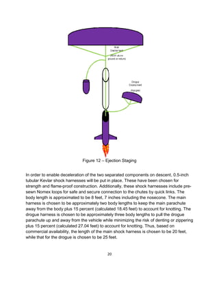
Download to read offline


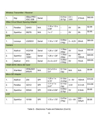
![18
should be no more than 15 feet per second in order to minimize damage to the launch
vehicle.
The size of the drogue parachute can then be estimated from D = 24√ , where D is
the ideal diameter of the drogue parachute and is the weight of the launch vehicle.
This gives D = 28.397 inches = 2.366 feet. Since commercial availability limits
parachute size to 0.5 foot increments, the diameter of the drogue is chosen to be 2.5
feet. By similar analysis, the size of the main parachute is estimated from D =
39.6√ . This gives D = 84.377 inches = 7.031 feet. The diameter of the main
parachute is chosen to be 8 feet. This is a conservative estimate with regard to terminal
velocity but slightly immoderate with regard to landing radius if wind speeds are in
excess of 15 miles per hour. However, programming full deployment to occur no later
than 500 feet from the ground on descent should allow for minimal drift. These
equations are derived from Newton’s Second Law of Motion s = 2w/ρv²c, where s =
reference area, w = vehicle weight, ρ = density of air, v = terminal velocity, and c = drag
coefficient as provided by the parachute manufacturer.
The chosen sizes of the main and drogue parachutes should be such that the kinetic
energy of each independent (tethered) section of the launch vehicle upon landing is no
greater than 75 foot-pounds. Based on Newton’s Second Law of Motion, with the
assumptions of constant descent rate between ejections and simple downward motion,
the maximum descent rate upon ejection of each parachute is given by
v =√ .
In the above equation, note that w = vehicle weight in pound-mass, ρ = sea-level air
density at 70 degrees Fahrenheit = 0.075 pound-force per cubic foot, c = drag
coefficient, and s = surface area of each parachute dome = π(height)²[3*(radius) –
(height)] where height is assumed to be *(radius). With a total vehicle weight of
20 pounds = 320 ounces = 9.24 kilograms, the maximum descent rate for the first 4,780
feet upon drogue release at apogee is 73.47 feet per second = 22.39 meters per
second. Upon release of the main this drops to a maximum 12.83 feet per second =
3.91 meters per second descent rate for the remaining 500 feet.
Descent time after each event can be calculated from t = d/v, where d = distance
travelled in feet and v = maximum descent velocity. The first 4,780 feet of descent thus
takes no less than 65.06 seconds. Similarly the final 500 feet of descent takes no less](https://image.slidesharecdn.com/2e33dd32-9174-4298-8073-303596f4af5e-160106204306/85/NASA-RFP-27-320.jpg)


![70
Appendix C – Pre Launch Check List
Compile this checklist at the launch pad under the supervision of a Launch Safety Officer
(LSO) or appropriately certified NAR member. This checklist is to be completed and
passed before the rocket is cleared to launch.
Structures: Inspect each component for security and flight worthiness
1. [ ] Nosecone
2. [ ] Airframe
3. [ ] Fins
4. [ ] Rail Buttons
5. [ ] Motor Retainer
Recovery: Inspect each component for security and flight worthiness.
6. [ ] Shock Cord –Secured between nosecone and forward ring eye-bolts
7. [ ] Chute Protector
8. [ ] Parachute – Fold and install parachute according to the parachute folding
direction.
Propulsion: Inspect each component for security and flight worthiness.
9. [ ] Motor Case—Inspect for cleanliness
10. [ ] Motor Reload – Install into motor case per manufacturer’s instructions
11. [ ] Motor Retainer – Remove retainer cap, install motor, and reinstall retainer
cap securely.
12. [ ] Igniter – Located and retain igniter until needed. ***DO NOT INSERT
IGNITER***
Documentation:
13. [ ] Complete this checklist below and inform the Safety Officer, as well the
Team Mentor for review.
Checklist is completed by:
[name]_ [date]_
Checklist is reviewed by:
[name]_ [date]_
Proceed to Range Safety Officer (RSO) for final inspection and further instruction.](https://image.slidesharecdn.com/2e33dd32-9174-4298-8073-303596f4af5e-160106204306/85/NASA-RFP-79-320.jpg)
![MSDS – ProX Rocket Motor Reload Kits Version 3.00
Revision Date. 2010-08-10
71
Appendix D – Launch Pad Checklist
Compile this checklist at the launch pad under the supervision of a Launch Safety
Officer (LSO) or appropriately certified NAR member. This checklist is to be completed
and passed before the rocket is cleared to launch.
Launch Pad:
1. [ ] Launch Rail – Inspect launch rail for excessive corrosion or snags that
would risk the rocket jamming on the rail
2. [ ] Rocket – slide the rocket down onto the rail until it is against the rest.
Propulsion: - The Launch Control System (LCS) pad bank must be switched OFF.
3. [ ] insert igniter fully into the rocket motor thru the nozzle and install
the nozzle cover.
4. [ ] Strip 1” – 2” of the wire’s sheath to expose both wire cores.
5. [ ] Short LCS circuit by tapping both alligator clips together.
6. [ ] Connect one wire core to each alligator clip wrapping the excess
wire around the clip.
NOTE: The LSO may ask you to do any number of these steps in a different order.
Be prepared to deviate from this checklist. If you feel you are being asked to do
anything unsafe, respectfully ask for clarification on the reason for the change.
7. [ ] Before returning to the RSO tent, switch the LCS pad bank ON if you are
the last person leaving the area.
Documentation:
8. [ ] Complete this checklist below and inform the Safety Officer, as well the
Team Mentor for review.
Checklist is completed by: [name]
[date]
Checklist is reviewed by: [name]
[date]
Return to the RSO tent with your Flight Card pad number filled in. After flight,
remain behind RSO line until the field is reopened.](https://image.slidesharecdn.com/2e33dd32-9174-4298-8073-303596f4af5e-160106204306/85/NASA-RFP-80-320.jpg)


![88
SECTION 5: FIRE FIGHTING MEASURES
5.1 FLAMMABLE PROPERTIES
Autoignition temperature No Data Available
Flash Point >=340 ºF [Test Method: Closed Cup]
Flammable Limits - LEL Not Applicable
Flammable Limits - UEL Not Applicable
5.2 EXTINGUISHING MEDIA
Use fire extinguishers with class B extinguishing agents (e.g., dry chemical, carbon dioxide).
5.3 PROTECTION OF FIRE FIGHTERS
Special Fire Fighting Procedures: Water may not effectively extinguish fire; however, it should be used to keep fire-exposed
containers and surfaces cool and prevent explosive rupture. Water may be used to blanket the fire. Wear full protective equipment
(Bunker Gear) and a self-contained breathing apparatus (SCBA).
Unusual Fire and Explosion Hazards: No unusual fire or explosion hazards are anticipated.
Note: See STABILITY AND REACTIVITY (SECTION 10) for hazardous combustion and thermal decomposition
information.
SECTION 6: ACCIDENTAL RELEASE MEASURES
Personal precautions
Evacuate unprotected and untrained personnel from hazard area. The spill should be cleaned up by qualified personnel. Ventilate the
area with fresh air.
Environmental procedures
For larger spills, cover drains and build dikes to prevent entry into sewer systems or bodies of water. Collect the resulting residue
containing solution. Place in a closed container approved for transportation by appropriate authorities. Dispose of collected material
as soon as possible.
Clean-up methods
Observe precautions from other sections. Call 3M- HELPS line (1-800-364-3577) for more information on handling and managing the
spill. Contain spill. Working from around the edges of the spill inward, cover with bentonite, vermiculite, or commercially available
inorganic absorbent material. Mix in sufficient absorbent until it appears dry. Collect as much of the spilled material as possible.
Clean up residue with an appropriate solvent selected by a qualified and authorized person. Ventilate the area with fresh air. Read and
follow safety precautions on the solvent label and MSDS.
In the event of a release of this material, the user should determine if the release qualifies as reportable according to
local, state, and federal regulations.
SECTION 7: HANDLING AND STORAGE
7.1 HANDLING](https://image.slidesharecdn.com/2e33dd32-9174-4298-8073-303596f4af5e-160106204306/85/NASA-RFP-97-320.jpg)
![90
SOURCE OF EXPOSURE LIMIT DATA:
ACGIH: American Conference of Governmental Industrial Hygienists
CMRG: Chemical Manufacturer Recommended Guideline
OSHA: Occupational Safety and Health Administration
AIHA: American Industrial Hygiene Association Workplace Environmental Exposure Level (WEEL)
SECTION 9: PHYSICAL AND CHEMICAL PROPERTIES
Specific Physical Form: Paste
Odor, Color, Grade: Black, very mild odor.
General Physical Form: Liquid
Autoignition temperature No Data Available
Flash Point >=340 ºF [Test Method: Closed Cup]
Flammable Limits - LEL Not Applicable
Flammable Limits - UEL Not Applicable
Boiling point >=200 ºC
Density 1.14 g/ml
Vapor Density Not Applicable
Vapor Pressure Not Applicable
Specific Gravity 1.14 [Ref Std: WATER=1]
pH Not Applicable
Melting point No Data Available
Solubility in Water Nil Evaporation
rate Not Applicable
Kow - Oct/Water partition coef No Data Available
Percent volatile < 0.5 % weight
VOC Less H2O & Exempt Solvents 2 g/l [Test Method: tested per EPA method 24]
Viscosity 22000 - 45000 centipoise [@ 73.4 ºF]
SECTION 10: STABILITY AND REACTIVITY
Stability: Stable.
Materials and Conditions to Avoid:
10.1 Conditions to avoid
Heat
10.2 Materials to avoid
Strong oxidizing agents
Hazardous Polymerization: Hazardous polymerization will not occur.
Hazardous Decomposition or By-Products](https://image.slidesharecdn.com/2e33dd32-9174-4298-8073-303596f4af5e-160106204306/85/NASA-RFP-99-320.jpg)


![96
5.1 FLAMMABLE PROPERTIES
Autoignition temperature No Data Available
Flash Point >=340 ºF [Test Method: Closed Cup]
Flammable Limits(LEL) Not Applicable
Flammable Limits(UEL) Not Applicable
5.2 EXTINGUISHING MEDIA
Use fire extinguishers with class B extinguishing agents (e.g., dry chemical, carbon dioxide).
5.3 PROTECTION OF FIRE FIGHTERS
Special Fire Fighting Procedures: Water may not effectively extinguish fire; however, it should be used to keep fire-exposed
containers and surfaces cool and prevent explosive rupture. Water may be used to blanket the fire. Wear full protective equipment
(Bunker Gear) and a self-contained breathing apparatus (SCBA).
Unusual Fire and Explosion Hazards: No unusual fire or explosion hazards are anticipated.
Note: See STABILITY AND REACTIVITY (SECTION 10) for hazardous combustion and thermal decomposition
information.
SECTION 6: ACCIDENTAL RELEASE MEASURES
6.1. Personal precautions, protective equipment and emergency procedures
Evacuate unprotected and untrained personnel from hazard area. The spill should be cleaned up by qualified personnel. Ventilate the
area with fresh air. For large spill, or spills in confined spaces, provide mechanical ventilation to disperse or exhaust vapors, in
accordance with good industrial hygiene practice. Warning! A motor could be an ignition source and could cause flammable gases or
vapors in the spill area to burn or explode.
6.2. Environmental precautions
For larger spills, cover drains and build dikes to prevent entry into sewer systems or bodies of water. Collect the resulting residue
containing solution. Place in a closed container approved for transportation by appropriate authorities. Dispose of collected material
as soon as possible.
Clean-up methods
Observe precautions from other sections. Call 3M- HELPS line (1-800-364-3577) for more information on handling and managing the
spill. Contain spill. Working from around the edges of the spill inward, cover with bentonite, vermiculite, or commercially available
inorganic absorbent material. Mix in sufficient absorbent until it appears dry. Collect as much of the spilled material as possible.
Clean up residue with an appropriate solvent selected by a qualified and authorized person. Ventilate the area with fresh air. Read and
follow safety precautions on the solvent label and MSDS.
In the event of a release of this material, the user should determine if the release qualifies as reportable according to
local, state, and federal regulations.
SECTION 7: HANDLING AND STORAGE
7.1 HANDLING
Avoid eye contact. Do not eat, drink or smoke when using this product. Wash exposed areas thoroughly with soap and water. Avoid](https://image.slidesharecdn.com/2e33dd32-9174-4298-8073-303596f4af5e-160106204306/85/NASA-RFP-105-320.jpg)

![98
OSHA: Occupational Safety and Health Administration
AIHA: American Industrial Hygiene Association Workplace Environmental Exposure Level (WEEL)
SECTION 9: PHYSICAL AND CHEMICAL PROPERTIES
Specific Physical Form: Paste
Odor, Color, Grade: Amber, very mild pungent odor.
General Physical Form: Liquid
Autoignition temperature No Data Available
Flash Point >=340 ºF [Test Method: Closed Cup]
Flammable Limits(LEL) Not Applicable
Flammable Limits(UEL) Not Applicable
Boiling Point >=175 ºC
Density 1.12 g/ml
Vapor Density Not Applicable
Vapor Pressure Not Applicable
Specific Gravity 1.12 [Ref Std: WATER=1]
pH Not Applicable
Melting point No Data Available
Solubility in Water Slight (less than 10%)
Evaporation rate Not Applicable
Hazardous Air Pollutants 0 % weight [Test Method: Calculated]
Volatile Organic Compounds < 1 g/l [Test Method: tested per EPA method 24] [Details: EU
VOC content]
Percent volatile < 0.5 % weight [Test Method: Estimated]
VOC Less H2O & Exempt Solvents 11 g/l [Test Method: tested per EPA method 24]
VOC Less H2O & Exempt Solvents 4 g/l [Test Method: tested per EPA method 24] [Details: when used
as intended with Part B]
Viscosity 8000 - 14000 centipoise [@ 73.4 ºF]
SECTION 10: STABILITY AND REACTIVITY
Stability: Stable.
Materials and Conditions to Avoid:
10.1 Conditions to avoid
Heat is generated during cure. Do not cure a mass larger than 50 grams in a confined space to prevent a premature reaction (exothem)
with production of intense heat and smoke.
10.2 Materials to avoid
Strong oxidizing agents
Hazardous Polymerization: Hazardous polymerization will not occur.
Hazardous Decomposition or By-Products](https://image.slidesharecdn.com/2e33dd32-9174-4298-8073-303596f4af5e-160106204306/85/NASA-RFP-107-320.jpg)


![104
RadioShack Cat. No. 64-035 [B] p. 2
Special Fire Fighting Precautions
USE NIOSH/MSHA APPROVED SELF-coNTAINED BREATHING APPARATUSAND FULL BODY
PROTECTIVE CLOTHING.
1
NFPARATING 1 0 HEALTH 1, FLAMMABILITY 1,
0
4. HEALTH HAZARD INFORMAnON
REACT.nnTYO,SPECIALO
Primary Routes of Entry
INGESTION X INHALATION ABSORPTION
carcinogenecity
THIS PRODUCT HAS NOT BEEN LISTED AS A SUSPECT CARCINOGEN BY NTP, IARC OROSHA.
Acute overexposure(symptoms and effects)
SEVERE SHORT-TERM OVEREXPOSURE MAY LEAD TO CENTRAL NERVOUSSYSTEM DISORDERS,
CHARACTERIZED BY DROWSINESS,SEIZURES,COMA AND DEATH. IT SHOULD BE
RECOGNIZED THAT EXPOSURESOF THIS MAGNITUDE IN AN INDUSTRIAL ENVIRONMENT ARE
EXTREMELY UNUKELY.
Chronic overex:posure(symptoms and effects)
PROLONGED OVEREXPOSURE TO LEAD CAN RESULT IN SYSTEMIC POISONING WITH
SYMPTOMSOF METALUC TASTE, ANEMIA, INSOMNIA, WEAKNESS,CONSTIPATION,
ABDOMINAL PAIN,GASTROINTEmNAL DISORDERS, JOINT AND MUSCULAR PAIN AND
MUSCULAR WEAKNESS AND MAY CAUSE DAMAGE TO THE BLOOD-FORMING, NERVOUS,
KIDNEYS AND REPRODUCTIVE SYSTEMS.
MedicalConditions Possibly Aggravated By Exposure
DISEASESOF THEBLOOD AND BLOOD FORMING ORGANS, KIDNEYS, NERVOUS AND POSSIBLY
REPRODUCTIVE SYSTEMS.
First Aid Procedures
INHALATION:REMOVE FROM EXPOSURE AND CALL A PHYSICIAN.
SKIN CONTACT:WASH AFFECTED AREAS WITH SOAP AND WATER. IF BURNSSHOULD OCCUR
FROM MOLTEN METAL TREAT FOR BURN AND GET IMMEDIATE MEDICAL ASSISTANCE.
EYE CONTACT:FLUSH EYES WITH WATER FOR 15 MINUTES,CALL A PHYSICIAN.
INGESTION:INGEST LARGE QUANTITIESOF WATER, CALL A PHYSICIAN.
5. PRECAUnONS/PROCEDURES
OVERHEATING OF ALLOY CAN PRODUCE METAL FUMES AND OXIDES. MACHINING
OPERATIONSSUCH AS GRINDING, SAWING OR BUFFING CAN GENERATE AIRBORNE
PARTICULATE IN THE WORK AREA. EXPOSURE LEVELS INDICATED IN SECTION 1ARE
RELEVANT TO THESE AND OTHER OPERATIONS.
NormalHandling
USE OF APPROVED RESPIRATORS IS REQUIRED FOR APPLICATIONS WHERE ADEQUATE
VENTILATION CANNOT BE PROVIDED. ACTIVITIESWHICH GENERATE DUST OR FUME SHOULD
BE AVOIDED. WHEN MELTED,THE TEMPERATURE SHOULD BE KEPT AS LOW AS POSSIBLE.](https://image.slidesharecdn.com/2e33dd32-9174-4298-8073-303596f4af5e-160106204306/85/NASA-RFP-113-320.jpg)
![105
RadioShack Cat. No. 64-035 [B] p. 3
Spill or Leak:
ANY METHOD THAT KEEPS DUST TO A MINIMUMISACCEPTABLE. VACUUMING ISPREFERRED.
USE OF APPROVED RESPIRATORY PROTECTION WHERE POSSIBILITY OF DUST/FUME
EXPOSURE EXISTS. DO NOT USE COMPRESSED AIR FOR CLEANING.
PersonalHygiene:
AVOID INHALATIONOR INGESTION. PRACTICE GOOD HOUSEKEEPING AND PERSONAL
HYGIENE PROCEDURES. A SHOWER IS RECOMMENDEDIFSIGNIFICANT DUST EXPOSURE
OCCURS.
Engineering Controls:
LOCAL EXHAUST VENTILATION IS RECOMMENDED FOR DUST AND/OR FUME GENERATION
OPERATIONS WHERE AIRBORNE EXPOSURES MAY EXCEED PERMISSIBLE AIR
CONCENTRATIONS.
Storage:
GENERAL STORAGE PROCEDURES ACCEPTABLE.
SpecialPrecautions,Procedures,Label Instruction:
SPECIAL ATTENTION IS DRAWN TO THE REQUIREMENTS OF THE OSHA LEAD STANDARD
(1910.1025) AND RESPIRATOR STANDARD (1910.134) SHOULD AIRBORNE EXPOSURES
EXCEED THE OSHA ACTION LEVEL OR PEL.
6. PERSONAL PROTECTIVE EQUIPMENT
Respiratory Prob!ction:
WHERE AIRBORNE EXPOSURES MAY EXCEEDOSHA/ ACGIH PERMISSIBLE AIR
CONCENTRATIONS,THE MINIMUM RESPIRATORY PROTECTION RECOMMENDED IS A
NEGATIVE PRESSURE AIR PURIFYING RESPIRATOR WITH CARTRIDGES THAT ARE
NIOSH/MSHA APPROVED AGAINST DUST,FUMES AND MISTS HAVING A TWA NOT LESS THAN
0/05 MG/CU M.
Eyes and Face:
SAFETY GLASSES RECOMMENDED WHERE THE POSSIBIUTY OF GETTING DUST PARTICLES IN
EYES EXISTS OR WHEN HANDUNG MOLTEN METAL
Other Clothing and Equipment
GLOVES AND OTHER PROTECTIVE CLOTHING RECOMMENDED IF SKIN CONTACTIS
APPRECIABLE.
7. REACTIVITY DATA
Stability: STABLE Conditions to Avoid: NOT APPUCABLE
Incompatibility: STRONG OXIDIZERS MAY CAUSE VIOLENT REACTION.
Hazardous Decomposition Products:AT TEMPERATURES ABOVE THE MELTING POINT,OXIC
FUMES OR VAPORS MAY BE EMITTED.
8. ENVIRONMENTAL
Regulated by DOT? NO](https://image.slidesharecdn.com/2e33dd32-9174-4298-8073-303596f4af5e-160106204306/85/NASA-RFP-114-320.jpg)
![Revised On 05/21/2012
106
Rad ioShack Cat. No. 64-035 [B] p. 4
Waste Disposal Method(DISPOSER MUST COMPLY WITH FEDERAL, STATE AND LOCAL DISPOSAL OR
DISCHARGE LAWS)
IF HAZARDOUS UNDER 40 CFR 261, SUBPARTS BAND C, MATERIAL MUST BE TREATED OR
DISPOSED IN A FACILITY MEETING THE REQUIREMENTS OF 40 CFR 254 OR 265. IF NON- HAZARDOUS,MATERIAL
SHOULD BE DISPOSED IN A FACILITY MEETING THEREQUIREMENTS OF 40 CFR 257.
RCRA Status of Unused Material:
IF DISCARGED IN UNALTERED FORM, MATERIAL SHOULD BE TESTED TO DETERMINE IF IT
MUST BE CLASSIFIED AS A HAZARDOUS WASTE FORDISPOSAL PURPOSES. UNDER SPECIFIC CIRCUMSTANCES,
APPUCATION CAN BE MADE TOTHE EPA ADMINISTRATOR TO HAVE A PARTICULAR WASTE DESIGNATED NON-
HAZARDOUS.
9. ADDmONALINFORMATION
Precautions to be takenin handling and storing: NONE
Other Precautions: NONE
This MaterialSMetyData Sheet is offered rtJr your inrtJrmation, cotJSideration and investigation. Bow ElectronicSolders provides no
warranties, either expressed or implied, and iiSSI/mes no responsfbillties ror the accuracy or completeness of the data contained in
this document. The data In this Material SafetyData Sheet relates to this productand doe$ not relateto use in combination with
any other materialor In any process.](https://image.slidesharecdn.com/2e33dd32-9174-4298-8073-303596f4af5e-160106204306/85/NASA-RFP-115-320.jpg)


![125
Appendix H: Federal Aviation Regulations 14 CFR, Subchapter F, Part 101,
Subpart C
Federal Aviation Administration, DOT § 101.23
or kite below the top of any structure
and within 250 feet of it, if that shield-
ed operation does not obscure any
lighting on the structure.
§ 101.15 Notice requirements.
No person may operate an unshielded
moored balloon or kite more than 150
feet above the surface of the earth un-
less, at least 24 hours before beginning
the operation, he gives the following
information to the FAA ATC facility
that is nearest to the place of intended
operation:
(a) The names and addresses of the
owners and operators.
(b) The size of the balloon or the size
and weight of the kite.
(c) The location of the operation.
(d) The height above the surface of
the earth at which the balloon or kite
is to be operated.
(e) The date, time, and duration of
the operation.
§101.17 Lighting and marking require-
ments.
(a) No person may operate a moored
balloon or kite, between sunset and
sunrise unless the balloon or kite, and
its mooring lines, are lighted so as to
give a visual warning equal to that re-
quired for obstructions to air naviga-
tion in the FAA publication ‘‘Obstruc-
tion Marking and Lighting’’.
(b) No person may operate a moored
balloon or kite between sunrise and
sunset unless its mooring lines have
colored pennants or streamers attached
at not more than 50 foot intervals be-
ginning at 150 feet above the surface of
the earth and visible for at least one
mile.
(Sec. 6(c), Department of Transportation Act
(49 U.S.C. 1655(c)))
[Doc. No. 1580, 28 FR 6722, June 29, 1963, as
amended by Amdt. 101–4, 39 FR 22252, June
21, 1974]
§101.19 Rapid deflation device.
No person may operate a moored bal-
loon unless it has a device that will
automatically and rapidly deflate the
balloon if it escapes from its moorings.
If the device does not function prop-
erly, the operator shall immediately
notify the nearest ATC facility of the
location and time of the escape and the
estimated flight path of the balloon.
Subpart C— Amateur Rockets
§ 101.21 Applicability.
(a) This subpart applies to operating
unmanned rockets. However, a person
operating an unmanned rocket within
a restricted area must comply with
§ 101.25(b)(7)(ii) and with any additional
limitations imposed by the using or
controlling agency.
(b) A person operating an unmanned
rocket other than an amateur rocket
as defined in § 1.1 of this chapter must
comply with 14 CFR Chapter III.
[Doc. No. FAA–2007–27390, 73 FR 73781, Dec. 4,
2008]
§ 101.22 Definitions.
The following definitions apply to
this subpart:
(a) Class 1—Model Rocket means an
amateur rocket that:
(1) Uses no more than 125 grams (4.4
ounces) of propellant;
(2) Uses a slow-burning propellant;
(3) Is made of paper, wood, or break-
able plastic;
(4) Contains no substantial metal
parts; and
(5) Weighs no more than 1,500 grams
(53 ounces), including the propellant.
(b) Class 2—High-Power Rocket means
an amateur rocket other than a model
rocket that is propelled by a motor or
motors having a combined total im-
pulse of 40,960 Newton-seconds (9,208
pound-seconds) or less.
(c) Class 3—Advanced High-Power
Rocket means an amateur rocket other
than a model rocket or high-power
rocket.
[Doc. No. FAA–2007–27390, 73 FR 73781, Dec. 4,
2008]
§101.23 General operating limitations.
(a) You must operate an amateur
rocket in such a manner that it:
(1) Is launched on a suborbital trajec-
tory;
(2) When launched, must not cross
into the territory of a foreign country
unless an agreement is in place be-
tween the United States and the coun-
try of concern;
(3) Is unmanned; and
(4) Does not create a hazard to per-
sons, property, or other aircraft.](https://image.slidesharecdn.com/2e33dd32-9174-4298-8073-303596f4af5e-160106204306/85/NASA-RFP-134-320.jpg)
![126
§ 101.25
(b) The FAA may specify additional
operating limitations necessary to en-
sure that air traffic is not adversely af-
fected, and public safety is not jeopard-
ized.
[Doc. No. FAA–2007–27390, 73 FR 73781, Dec. 4,
2008]
§ 101.25 Operating limitations for
Class 2-High Power Rockets and
Class 3-Advanced High Power Rock-
ets.
When operating Class 2-High Power
Rockets or Class 3-Advanced High Power
Rockets, you must comply with the
General Operating Limitations of
§101.23. In addition, you must not oper-
ate Class 2-High Power Rockets or Class
3-Advanced High Power Rockets—
(a) At any altitude where clouds or
obscuring phenomena of more than
five-tenths coverage prevails;
(b) At any altitude where the hori-
zontal visibility is less than five miles;
(c) Into any cloud;
(d) Between sunset and sunrise with-
out prior authorization from the FAA;
(e) Within 9.26 kilometers (5 nautical
miles) of any airport boundary without
prior authorization from the FAA;
(f) In controlled airspace without
prior authorization from the FAA;
(g) Unless you observe the greater of
the following separation distances from
any person or property that is not asso-
ciated with the operations:
(1) Not less than one-quarter the
maximum expected altitude;
(2) 457 meters (1,500 feet.);
(h) Unless a person at least eighteen
years old is present, is charged with en-
suring the safety of the operation, and
has final approval authority for initi-
ating high-power rocket flight; and
(i) Unless reasonable precautions are
provided to report and control a fire
caused by rocket activities.
[74 FR 38092, July 31, 2009, as amended by
Amdt. 101–8, 74 FR 47435, Sept. 16, 2009]
§ 101.27 ATC notification for all
launches.
No person may operate an unmanned
rocket other than a Class 1—Model
Rocket unless that person gives the
following information to the FAA ATC
facility nearest to the place of in-
tended operation no less than 24 hours
14 CFR Ch. I (1–1–12 Edition)
before and no more than three days be-
fore beginning the operation:
(a) The name and address of the oper-
ator; except when there are multiple
participants at a single event, the
name and address of the person so des-
ignated as the event launch coordi-
nator, whose duties include coordina-
tion of the required launch data esti-
mates and coordinating the launch
event;
(b) Date and time the activity will
begin;
(c) Radius of the affected area on the
ground in nautical miles;
(d) Location of the center of the af-
fected area in latitude and longitude
coordinates;
(e) Highest affected altitude;
(f) Duration of the activity;
(g) Any other pertinent information
requested by the ATCfacility.
[Doc. No. FAA–2007–27390, 73 FR 73781, Dec. 4,
2008, as amended at Doc. No. FAA–2007–27390,
74 FR 31843, July 6, 2009]
§ 101.29 Information requirements.
(a) Class 2—High-Power Rockets. When
a Class 2—High-Power Rocket requires
a certificate of waiver or authoriza-
tion, the person planning the operation
must provide the information below on
each type of rocket to the FAA at least
45 days before the proposed operation.
The FAA may request additional infor-
mation if necessary to ensure the pro-
posed operations can be safely con-
ducted. The information shall include
for each type of Class 2 rocket expected
to be flown:
(1) Estimated number of rockets,
(2) Type of propulsion (liquid or
solid), fuel(s) and oxidizer(s),
(3) Description of the launcher(s)
planned to be used, including any air-
borne platform(s),
(4) Description of recovery system,
(5) Highest altitude, above ground
level, expected to be reached,
(6) Launch site latitude, longitude,
and elevation, and
(7) Any additional safety procedures
that willbe followed.
(b) Class 3—Advanced High-Power
Rockets. When a Class 3—Advanced
High-Power Rocket requires a certifi-
cate of waiver or authorization the per-
son planning the operation must pro-
vide the information below for each](https://image.slidesharecdn.com/2e33dd32-9174-4298-8073-303596f4af5e-160106204306/85/NASA-RFP-135-320.jpg)
![127
Federal Aviation Administration, DOT § 101.35
type of rocket to the FAA at least 45
days before the proposed operation.
The FAA may request additional infor-
mation if necessary to ensure the pro-
posed operations can be safely con-
ducted. The information shall include
for each type of Class 3 rocket expected
to be flown:
(1) The information requirements of
paragraph (a) of this section,
(2) Maximum possible range,
(3) The dynamic stability character-
istics for the entire flight profile,
(4) A description of all major rocket
systems, including structural, pneu-
matic, propellant, propulsion, ignition,
electrical, avionics, recovery, wind-
weighting, flight control, and tracking,
(5) A description of other support
equipment necessary for a safe oper-
ation,
(6) The planned flight profile and se-
quence of events,
(7) All nominal impact areas, includ-
ing those for any spent motors and
other discarded hardware, within three
standard deviations of the mean im-
pact point,
(8) Launch commit criteria,
(9) Countdown procedures, and
(10) Mishap procedures.
[Doc. No. FAA–2007–27390, 73 FR 73781, Dec. 4,
2008, as amended at Doc. No. FAA–2007–27390,
74 FR 31843, July 6, 2009]
Subpart D—Unmanned Free
Balloons
SOURCE: Docket No. 1457, 29 FR 47, Jan. 3,
1964, unless otherwise noted.
§ 101.31 Applicability.
This subpart applies to the operation
of unmanned free balloons. However, a
person operating an unmanned free bal-
loon within a restricted area must
comply only with § 101.33 (d) and (e) and
with any additional limitations that
are imposed by the using or controlling
agency, as appropriate.
§101.33 Operating limitations.
No person may operate an unmanned
free balloon—
(a) Unless otherwise authorized by
ATC, below 2,000 feet above the surface
within the lateral boundaries of the
surface areas of Class B, Class C, Class
D, or Class E airspace designated for an
airport;
(b) At any altitude where there are
clouds or obscuring phenomena of more
than five-tenths coverage;
(c) At any altitude below 60,000 feet
standard pressure altitude where the
horizontal visibility is less than five
miles;
(d) During the first 1,000 feet of as-
cent, over a congested area of a city,
town, or settlement or an open-air as-
sembly of persons not associated with
the operation; or
(e) In such a manner that impact of
the balloon, or part thereof including
its payload, with the surface creates a
hazard to persons or property not asso-
ciated with the operation.
[Doc. No. 1457, 29 FR 47, Jan. 3, 1964, as
amended by Amdt. 101–5, 56 FR 65662, Dec. 17,
1991]
§101.35 Equipment and marking re-
quirements.
(a) No person may operate an un-
manned free balloon unless—
(1) It is equipped with at least two
payload cut-down systems or devices
that operate independently of each
other;
(2) At least two methods, systems,
devices, or combinations thereof, that
function independently of each other,
are employed for terminating the
flight of the balloon envelope; and
(3) The balloon envelope is equipped
with a radar reflective device(s) or ma-
terial that will present an echo to sur-
face radar operating in the 200 MHz to
2700 MHz frequency range.
The operator shall activate the appro-
priate devices required by paragraphs
(a) (1) and (2) of this section when
weather conditions are less than those
prescribed for operation under this sub-
part, or if a malfunction or any other
reason makes the further operation
hazardous to other air traffic or to per-
sons and property on the surface.
(b) No person may operate an un-
manned free balloon below 60,000 feet
standard pressure altitude between
sunset and sunrise (as corrected to the
altitude of operation) unless the bal-
loon and its attachments and payload,
whether or not they become separated
during the operation, are equipped with
lights that are visible for at least 5](https://image.slidesharecdn.com/2e33dd32-9174-4298-8073-303596f4af5e-160106204306/85/NASA-RFP-136-320.jpg)

![129
roads, utilities and other facilities which
could be damaged if the magazine
exploded. Indicate the distance between
the magazine and the feature.
(e) The materials (including dimensions and
thicknesses) used for the structure (e.g.,
concrete, corrugated iron over wood,
plywood, tin and earth, etc.).
(f) The security, physical safeguards, locks,
safety equipment, and anti-theft
measures.
(g) The dimensions and capacity of each
magazine.
(h) The class of explosive materials to be
stored in each magazine.
(i) The owner(s) of the magazine, if other
than the applicant.
(j) The names and telephone numbers of
individuals who could open the magazines
for inspection by ATF officers.
(k) Any special conditions, such as
inaccessibility in winter, etc.
(l) [ADDENDUM] A diagram of the premises,
providing much of the required descriptive
information set out above (preparation by
an engineer is not required). [75 CB 79]
2. 27 CFR 55.11: MEANING OF TERMS
(Also § 55.206)
An office or repair shop used in connection
with the manufacture, etc. of explosive
materials is not an “inhabited building.”
ATF Rul. 75-20
ATF has held that a building, such as an office
or repair shop, which is a part of the premises of
an explosives manufacturer and is used in
connection with the manufacture, transportation,
storage, or use of explosive materials, is not an
“inhabited building.”
Section 55.11 of 27 CFR defines inhabited
building as “any building regularly occupied in
whole or in part as a habitation for human
beings, or any church, schoolhouse, railroad
station, store, or other structure where people
are accustomed to assemble, except any
building occupied in connection with the
manufacture, transportation, storage, or use of
explosive materials.”
Regulations in 27 CFR §§ 55.206 and 55.218
set forth provisions concerning the location of
storage facilities and the minimum distances
such storage facilities may be located from,
among other things, “inhabited buildings.”
These provisions are intended to provide
protection to persons who inhabit buildings
located near premises where explosives are
manufactured, stored, etc. However, it is the
intent of § 55.11 to exempt buildings used by the
explosives industry in connection with the
manufacture, transportation, storage, or use of
explosive materials from the table of distance
requirements on “inhabited buildings.” [75 CB
64]
3. 27 CFR 55.207: CONSTRUCTION OF
TYPE 1 MAGAZINES
(Also § 55.210)
Certain explosives storage facilities
meeting standards of construction
prescribed by the Department of Defense
Explosives Safety Board for such storage are
approved by the Bureau.
ATF Rul. 75-21
ATF has held that explosives storage facilities
with smooth-finished concrete floors that were
constructed under contract for the use of the
Department of Defense (DOD) and that are
presently being leased to licensees and
permittees for the storage of commercial
explosives are considered to be in compliance
with the requirements for nonsparking floors, as
set forth in 27 CFR §§ 55.207(a)(4), 55.207(b),
and 55.210, for the storage of all types of fully
packaged explosives, pyrotechnics and
propellants, with the exception of black powder.
Any other such magazines which have smooth
finished concrete floors and which meet or
exceed DOD construction specifications will also
be considered to be in compliance with the
requirements of Part 55 with respect to
nonsparking floors.
It is the responsibility of the licensee or
permittee to provide verification that such
facilities were manufactured under DOD
specifications or that the facilities meet or
exceed such specification standards.
If the Division Director determines that the
concrete floors of type 1 or type 4 magazines do
not meet the preceding requirements, he will
require such floors to be covered with a
nonsparking material, such as epoxy paint or
mastic. [75 CB 67]](https://image.slidesharecdn.com/2e33dd32-9174-4298-8073-303596f4af5e-160106204306/85/NASA-RFP-138-320.jpg)
![130
4. 27 CFR 55.41: LICENSES AND
PERMITS—GENERAL
Certain companies that manufacture
explosive materials for use in their own
operations are required to obtain licenses as
manufacturers of explosive materials.
ATF Rul. 75-31
ATF has held that companies, such as public
utility companies engaged in line and facility
construction, which manufacture explosives on a
regular or continual basis are considered to be
engaged in the business of manufacturing
explosive materials and must be appropriately
licensed as required by 18 U.S.C. 842.
The term “manufacturer” is defined in 18
U.S.C. 841(h) as “any person engaged in the
business of manufacturing explosive materials
for purposes of sale or distribution or for his own
use.”
Although the term “engaged in the business” is
not susceptible to a rigid definition within 18
U.S.C. §§ 841-848, it is interpreted to imply an
element of continuity or habitual practice; an
element clearly present in the operations of
companies described herein.
Therefore, these companies are considered to
be “engaged in the business” and must be
licensed as explosives manufacturers. [75 CB
65]
5. 27 CFR 55.109: IDENTIFICATION OF
EXPLOSIVE MATERIALS
Methods of marking containers of
explosive materials are prescribed.
ATF Rul. 75-35
ATF has held that any method or combination
of methods for affixing the required marks to the
immediate container of explosive materials, or
outside container used in the packaging thereof,
is authorized provided the identifying marks:
(1) Are legible
(2) Show all required information; and,
(3) Are not rendered indecipherable by
extended periods of storage.
Where it is desired to utilize a coding system
and to omit printed markings on the container, a
letterhead application displaying the coding to
be used and the manner of its application shall
be filed with and approved by the Director, ATF,
prior to the use of the proposed coding. Further,
where a manufacturer operates his plant for only
one shift during the day, the shift of manufacture
need not be shown.
It was found that liquid components of
explosive materials stored for a period of time in
polyethylene or other soft containers would seep
through the container walls, tending to render
illegible the inked, identifying marks on the
container.
A manufacturer’s proposal [subsequently
approved] of using a system of perforated
numbers and code symbols (similar to that used
on cancelled checks) to mark containers in
addition to other identifying marks stamped in
ink, was determined to continue to provide the
identification required by 27 CFR 55.109, even if
the ink later became illegible. [75 CB 65]
6. 27 CFR 55.11: MEANING OF TERMS—
STATE OF RESIDENCE
“State of residence” of business entities
who use explosive materials; distribution of
explosive materials by licensees to out-of-
State business entities other than licensees
and permittees; and distribution to
nonresident employees of such entities are
discussed.
ATF Rul. 76-4
ATF was asked to interpret the term “State of
residence” (in § 55.11) as it:
(1) Pertains to the distribution of explosive
materials to out-of-State corporations and other
business entities other than licensees and
permittees; and
(2) Relates to the distribution of explosive
materials to nonresident employees of such
business entities.
The Business Entity
If a person is a corporation or other business
entity, “State of residence” means the State in
which such corporation or other business entity
maintains a “place of business.” A business
entity establishing another “place of business” or
“job site” in another State would acquire a “State
of residence” in that State as well. This means
that a company engaged in construction work
would acquire a residence in each State wherein
its work is performed. Its place of business in](https://image.slidesharecdn.com/2e33dd32-9174-4298-8073-303596f4af5e-160106204306/85/NASA-RFP-139-320.jpg)
![131
those States would be the job sites at which
business is carried on. It would not be essential
to a determination of its State of residence that a
branch office be maintained in, or administrative
work be performed in, the States where job sites
are located.
Such a company would not need a permit to
acquire explosive materials from a licensee in a
State for use at job sites located therein. Form
5400.4, “Explosives Transaction Record,” would
show the out-of-State addresses of the business
entity as the principal place of business, and the
location of the job site as the local place of
business.
Nonresident Employees
The purpose of the data requested on Form
5400.4 is to identify the person authorized by the
business entity to make the purchase of
explosive materials on the entity’s behalf and to
assure the distributor that such person appears
on the required certified list of names of
representatives or agents authorized by the
business entity to acquire the materials.
Regulations (27 CFR § 55.105(e)), implementing
Title 18 U.S.C. 842(f), in part, provide that each
business entity acquiring explosive materials
shall furnish the distributing licensed dealer with
a current, certified list of the names of
representatives or agents authorized to acquire
explosive materials on behalf of such business
entity. The purpose of the data requested on
Form 5400.8, “Explosives Delivery Record,” is to
identify the employee of the business entity or
the employee of a carrier accepting delivery of
explosive materials on behalf of the distributee
at the distributor’s business premises.
Therefore:
In the case of business entities, the
information required on ATF Forms 5400.4 and
5400.8 with respect to employees or agents
arranging for the distribution is not for the
purpose of establishing the residence of such
persons but only for identification purposes. [76
CB 104]
7. 27 CFR 55.126: EXPLOSIVES
TRANSACTION RECORD
Under certain conditions, a single Form
5400.4 may be used to cover a series of
deliveries.
ATF Rul. 76-10
Under the provisions of 27 CFR § 55.126, a
sale or other distribution by a licensee or
permittee shall not be made to a nonlicensee or
nonpermittee unless the transaction is recorded
on a Form 5400.4. Under certain conditions, a
single Form 5400.4 may be used to cover a
series of deliveries.
When an initial sale has been consummated,
with partial deliveries to be made in the
immediate future, the requirements of § 55.126
will have been satisfied if the following steps are
taken:
(1) Form 5400.4 shall be executed at the time
the sale is initially made, although delivery
of the explosive material is extended over
a period of time not to exceed 30 days.
(2) The executed Form 5400.4 shall
subsequently be noted to accurately
reflect the date of each separate delivery
and describe each separate lot of
explosive materials delivered.
(3) In lieu of showing the separate deliveries
on the Form 5400.4, the proprietor may
attach to the executed form a copy of the
delivery record or a copy of the bill of
lading or commercial invoice covering
each delivery; provided that, as to each
such delivery, the attachment contains the
date of the delivery and all the information
required by Item 21 of Form 5400.4.
(4) All other regulatory requirements and
instructions relating to the completion of
the form must be complied with. [76 CB
105]
8. 27 CFR 55.207: CONSTRUCTION OF
TYPE 1 STORAGE FACILITIES
(Also § 55.208)
Alternate construction standards for
storage facilities for explosive materials are
prescribed.
ATF Rul. 76-18
Section 842(j) of 18 U.S.C. states: “It shall be
unlawful for any person to store any explosive
material in a manner not in conformity with
regulations promulgated by the Secretary. In
promulgating such regulations, the Secretary
shall take into consideration the class, type, and
quantity of explosive materials to be stored, as](https://image.slidesharecdn.com/2e33dd32-9174-4298-8073-303596f4af5e-160106204306/85/NASA-RFP-140-320.jpg)
![132
well as the standards of safety and security
recognized in the explosives industry.”
The regulations in 27 CFR §§ 55.207 and
55.208 prescribe types of storage facilities for
explosive materials and provide (among other
things) that such storage facilities shall be bullet-
resistant. Section 55.201(b) provides that
alternate storage facilities may be authorized for
the storage of explosive materials when it is
shown that such alternate facilities are or will be
constructed in a manner substantially equivalent
to the standards of construction contained in the
applicable regulations.
The term “bullet-resistant” means resistant to
penetration of a bullet of 150 grain M2 ball
ammunition having a nominal muzzle velocity of
2700 feet per second fired from a .30 caliber rifle
from a distance of 100 feet perpendicular to the
wall or door.
It has been determined that a wide range of
construction criteria meet the bullet-resistant
requirements of regulations for construction of
storage facilities for explosive materials.
In order to promote standards of safety and
security in the storage of explosive materials
while allowing the industry a wide latitude in the
selection of construction materials, it is held that
storage facilities (magazines) that are
constructed according to the following minimum
specifications are bullet-resistant and meet the
requirements of the regulations as set forth in 27
CFR Part 55 (All steel and wood dimensions are
actual thicknesses. To meet the concrete block
and brick dimensions indicated, the
manufacturers’ represented thicknesses may be
used).
(a) Exterior of 5/8 inch steel, lined with an
interior of any type of nonsparking
material.
(b) Exterior of 1/2 inch steel, lined with an
interior of not less than 3/8 inch plywood.
(c) Exterior of 3/8 inch steel, lined with an
interior of two inches of hardwood.
(d) Exterior of 3/8 inch steel, lined with an
interior of three inches of softwood or 2
1/4 inches of plywood.
(e) Exterior of 1/4 inch steel, lined with an
interior of three inches of hardwood.
(f) Exterior of 1/4 inch steel, lined with an
interior of five inches of softwood or 5 1/4
inches of plywood.
(g) Exterior of 1/4 inch steel, lined with an
intermediate layer of two inches of
hardwood and an interior lining of 1 1/2
inches of plywood.
(h) Exterior of 3/16 inch steel, lined with an
interior of four inches of hardwood.
(i) Exterior of 3/16 inch steel, lined with an
interior of seven inches of softwood or 6
3/4 inches of plywood.
(j) Exterior of 3/16 inch steel, lined with an
intermediate layer of three inches of
hardwood and an interior lining of 3/4 inch
of plywood.
(k) Exterior of 1/8 inch steel, lined with an
interior of five inches of hardwood.
(l) Exterior of 1/8 inch steel, lined with an
interior of nine inches of softwood.
(m) Exterior of 1/8 inch steel, lined with an
intermediate layer of four inches of
hardwood and an interior lining of 3/4 inch
plywood.
(n) Exterior of any type of fire-resistant
material which is structurally sound, lined
with an intermediate layer of four inches of
solid concrete block, OR four inches of
solid brick OR four inches of solid
concrete; AND, an interior lining of 1/2
inch plywood placed securely against the
masonry lining.
(o) Standard eight inch concrete block with
voids filled with well-tamped sand/cement
mixture.
(p) Standard eight inch solid brick.
(q) Exterior of any type of fire-resistant
material which is structurally sound, lined
with an intermediate six inch space filled
with well-tamped dry sand or well-tamped
sand/cement mixture.
(r) Exterior of 1/8 inch steel, lined with a first
intermediate layer of 3/4 inch plywood, a
second intermediate layer of 3 5/8 inches
of well-tamped dry sand or sand/cement
mixture and an interior lining of 3/4 inch
plywood.
(s) Exterior of any type of fire-resistant
material, lined with a first intermediate
layer of 3/4 inch plywood, a second
intermediate layer of 3 5/8 inches well-
tamped dry sand or sand/cement mixture,
a third intermediate layer of 3/4 inch
plywood, and a fourth intermediate layer of
two inches of hardwood OR 14 gauge
steel AND an interior lining of 3/4 inch
plywood.
(t) Eight inch thick solid concrete. [76 CB
106]
9. 27 CFR 55.213: QUANTITY AND
STORAGE RESTRICTIONS](https://image.slidesharecdn.com/2e33dd32-9174-4298-8073-303596f4af5e-160106204306/85/NASA-RFP-141-320.jpg)
![133
(Also § 55.208)
Alternate magazine construction standards
for storage of electric blasting caps with
other explosive materials are prescribed.
ATF Rul. 77-24
Section 842(j) of 18 U.S.C. states: “It shall be
unlawful for any person to store any explosive
material in a manner not in conformity with
regulations promulgated by the Secretary. In
promulgating such regulations, the Secretary
shall take into consideration the class, type, and
quantity of explosive materials to be stored, as
well as the standards of safety and security
recognized in the explosives industry.”
The regulations in 27 CFR § 55.213 restrict
the storage of blasting caps with other explosive
materials. Section 55.201(b) provides that
alternate storage magazines may be authorized
for the storage of explosive materials when it is
shown that such alternate magazines are or will
be constructed in a manner substantially
equivalent to the standards of construction
contained in the applicable regulations.
ATF recognizes that the transportation and
storage of explosive materials in the same
vehicle along with electric blasting caps is often
desired. The Institute of Makers of Explosives
established a recommended standard for such
transport in their Safety Library Publication No.
22, dated November 5, 1971 [revised January
1985]. This standard prescribes the minimum
construction criteria for:
(a) A container securely attached—
(1) Above the cab of the vehicle (see
Figure 1, Appendix A), and
(2) To the vehicle frame under the cargo
space (see Figure 2, Appendix A), or
(b) A built-in compartment in the cargo space
of the vehicle (see Appendix B).
In addition to motorized vehicles,
consideration was also given for the use of
similar criteria on portable wheeled trailers being
used as magazines under § 55.208(a) of the
regulations (see Appendix E).
In order to insure standards of safety and
security in the storage of explosive materials
while allowing the industry a proper latitude in
the construction of magazines, it is held that
vehicles used for transporting and for storing
explosive materials that are constructed in
conformity with the standards listed below, and
in compliance with all other safety and security
provisions contained in Part 55 (e.g., effectively
immobilized when unattended) will meet the
requirements of ATF regulations.
Even though constructed on the same vehicle,
each compartment will be considered as a
separate magazine. The two magazines on the
vehicle will, however, be considered as one
magazine when applying the American Table of
Distances [see Table at § 55.218].
Construction Standards For Storage of
Electric Blasting Caps (Non Mass-
Detonating)
a. The container or compartment must provide
for total enclosure of the electric blasting
caps.
b. The partition between the explosives
storage compartment and the electric
blasting cap compartment must be of
laminate construction consisting of A/C
grade or better exterior plywood, gypsum
board [sheetrock] and low carbon steel
plates. In order of arrangement, the
laminate must conform to the following, with
minimum thickness of each lamination as
indicated:
1/2 inch plywood
1/2 inch gypsum board [sheetrock],
1/8 inch low carbon steel, and,
1/4 inch plywood,
with the 1/4 inch plywood facing the
explosives storage compartment. See
Appendix C for details of laminate
construction. The door to the electric
blasting cap compartment must be of metal
construction or solid wood covered with
metal; the outside walls and top must be of
the same construction as the rest of the
vehicle or trailer. If high explosives or bullet
sensitive explosive materials are stored in
the vehicle, then the storage compartment of
the vehicle must be constructed so as to be
bullet-resistant.
c. As an alternative to the construction
requirements shown in paragraph b, a
container for use only as illustrated in
Appendix A may be used when constructed
as follows:
1. The top, lid or door, and the sides and
bottom of each container must be of
laminate construction consisting of A/C
grade or better exterior plywood, solid
hardwood, gypsum board [sheetrock], and
sheet metal. In order of arrangement, the
laminate must conform to the following,](https://image.slidesharecdn.com/2e33dd32-9174-4298-8073-303596f4af5e-160106204306/85/NASA-RFP-142-320.jpg)
![134
with minimum thickness of each
lamination as indicated:
1/4 inch plywood,
1 inch solid hardwood,
1/2 inch plywood,
1/2 inch gypsum board [sheetrock]
(OR 1/4 inch particle board), and
22 gauge sheet metal,
constructed inside to outside in that
order. See Appendix D for details of
laminate construction.
2. The hardwood must be fastened
together with wood screws, the 1/2 inch
plywood must be fastened to the
hardwood with wood screws, the inner 1/4
inch plywood must be fastened to the
hardwood with adhesive, and the 22
gauge sheet metal must be attached to
the exterior of the container with screws.
d. The laminate composite material must be
securely bound together by waterproof
adhesive or other equally effective means.
e. The steel plates at the joints of laminations
must be secured by continuous fillet welds.
f. All interior surfaces of the container or
compartment must be constructed so as to
prevent contact of contents with any
sparking metal.
g. There must be direct access to the container
or into a compartment from outside the
vehicle.
h. Each container or compartment must have a
snug fitting continuous piano-type
hinged lid or door equipped with a locking
device (or devices).
i. Without permitting direct access to contents
under normal conditions, the locking or
hinging mechanisms must permit at least
one edge of the lid or door to rise or move
outward at least 1/2 inch when subjected to
internal pressure.
j. The exterior of the container or compartment
must be weather-resistant. [77 CB 191]](https://image.slidesharecdn.com/2e33dd32-9174-4298-8073-303596f4af5e-160106204306/85/NASA-RFP-143-320.jpg)
![135
APPENDIX A APPENDIXB
PERMANENTLY MOUNTED CONTAINERS COMPARTMENTS
0
0
0
0
R.
Figure 1
0
REAR DOOR(S)
0>
(X)
F gure 1
F gure 2
NOTE: The configurations shown in Figures
1and 2 are equally applicable to
multi-axle and •cab-over• vehicles.
CAPS
NOTE: The configurations shown In Figures
1 and 2 are equally applicable to
multi-axle and •cab-over• vehicles.
REAR DOOR(S)
REAR DOOR(S)
(Diagrams: Courtesyof IME;]
[Diagrams: Courtesy of IME}
ATF Rul. 77-24, Appendix A and 8
-.....)
0)](https://image.slidesharecdn.com/2e33dd32-9174-4298-8073-303596f4af5e-160106204306/85/NASA-RFP-144-320.jpg)
![136
i ,.
APPENDIXC APPJ;NDIX E
PORTABLE WHEELED TRAILERS
INSIDE
112' PLvm?0D ---V'
(NCgradeor
better, exterior)
114' PLYliKJOD
(AIC grade or
better, exterior)
OUTSIDE
1/8' LOW CARBON STEEL
112' SHEETROCK
Cap Storage
Sketch of laminate construction for contain-
er or compartment for electric blasting caps
use, as illustrated In Appendix A. B, and E.
APPENDIXD
Figure 1
Cap Storage
Figure 3
;::.. ':"J- 22 GAUGE SHEET METAL
INSIDE OUTSIDE
:.· ··'"l '&--- 1/2' SHEETROCK or
114' PAFmCLE BOARD
t -! 112' PLY11MJ0D
----
114'PLYVIIOOD I i...:.: :
1:.:.-= 1IT HARDWOOD
Sketch of laminate construction for contain-
er or compartment for electric blasting caps;
restricted to use as illustrated in Appendix A.
[Diagrams: Courtesy of /ME]
Figure 2 Figure 4
0>
<D
ATF Rul. 77-24, Appendix C- E
-.....)
()1](https://image.slidesharecdn.com/2e33dd32-9174-4298-8073-303596f4af5e-160106204306/85/NASA-RFP-145-320.jpg)


The Tarleton Aeronautical Team submitted a proposal to participate in the 2012-2013 NASA University Student Launch Initiative. The team is comprised of nine students from Tarleton State University representing six STEM disciplines. They secured over $11,500 in funding and will have access to on-campus facilities as well as a 5,000 square foot off-campus launch facility. Their proposed rocket design is 103 inches long with a 4-inch body diameter utilizing a Cesaroni K1440 motor to carry a science payload to 5,515 feet.


![A Career in Teaching - Isobel Kerr [Scottish Teacher Recruitment Team]](https://cdn.slidesharecdn.com/ss_thumbnails/careersinteaching-110315101746-phpapp01-thumbnail.jpg?width=640&height=640&fit=bounds)


