Definition
• It isthe set of techniques that allows the
simultaneous transmission of multiple signals
across a single data link.
3.
Multiplexer - MUX
•It combines different transmission streams
into a single stream. (Many to One)
4.
Demultiplexer - DEMUX
•It separates the stream back into its
component transmissions and directs them to
their corresponding lines. (One to Many)
• Link is a physical path, whereas Channel refers
to the portion of a link that carries a
transmission.
5.
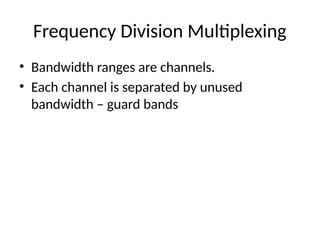
Frequency Division Multiplexing
•It is an analog technique that can be applied
when the bandwidth of a link is greater than
the combined bandwidths of the signals to be
transmitted.
• So signal generated by each sending device
modulate different carrier frequencies.
• Those modulated signals are combined into a
single composite signal that can be transported
by the link.
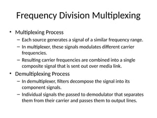
Frequency Division Multiplexing
•Multiplexing Process
– Each source generates a signal of a similar frequency range.
– In multiplexer, these signals modulates different carrier
frequencies.
– Resulting carrier frequencies are combined into a single
composite signal that is sent out over media link.
• Demultiplexing Process
– In demultiplexer, filters decompose the signal into its
component signals.
– Individual signals the passed to demodulator that separates
them from their carrier and passes them to output lines.
8.
Wavelength Division Multiplexing
•It is designed to use the high data rate of
capability of fiber-optic.
• It is also an analog technique.
• Process of same as of FDM but involves fiber-
optic and very high frequencies.
9.
Synchronous Time DivisionMultiplexing
• It is digital technique.
• It allows several connections to share the high
bandwidth of a link.
• Instead of sharing a portion of the bandwidth,
time is shared.
• In synchronous, each input connection has an
allotment in the output even if it is not
sending data.
10.
Synchronous Time DivisionMultiplexing
• Time Slot
– Each input connection is divided into units, each input occupies one
input time slot.
– Unit is bit, byte, or block of data.
– Each input unit becomes one output unit and occupies one output
time slot.
– Each output time slot is n times shorter than input time slot.
• Frame
– A round of data units from each input connections is called frame. So
for n connections, a frame is divided n times.
• Output link must be n times the data rate of a connection.
11.
Synchronous Time DivisionMultiplexing
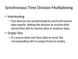
• Interleaving
– Two devices are synchronized to send and receive
data exactly. Setting the devices to receive their
actual time slot to receive data or produce data.
• Empty Slot
– If a source does not have data to send, the
corresponding slot in output frame is empty.
12.
Synchronous Time DivisionMultiplexing
• Data Rate Management
– There may be disparity in the input data rates.
Data rate must be same before sending data.
• Multilevel Multiplexing
– If data rate of input devices is a multiple of others.
• Multiple Slot Allocation
– Allocating more than one slot to single input line,
if data rate is multiple of others.
13.
Synchronous Time DivisionMultiplexing
• Pulse Stuffing
– If data rate of input lines is different
– Adding the bits to input line to make it equal to
highest.
• Frame Synchronizing
– To send and receive bits accurately, a bit, framing
bits, added beginning of each frame.
14.
Synchronous Time DivisionMultiplexing
• Slots are allocated dynamically, if it need to send
data.
• Receiver address is required, as there is no
relationship between inputs and outputs
• Slot size includes data as well as address and ratio
between data and address must be reasonable.
• No synchronization bit is required at frame level.
• Bandwidth capacity of the link is normally less
than the sum of the capacities of each channel.