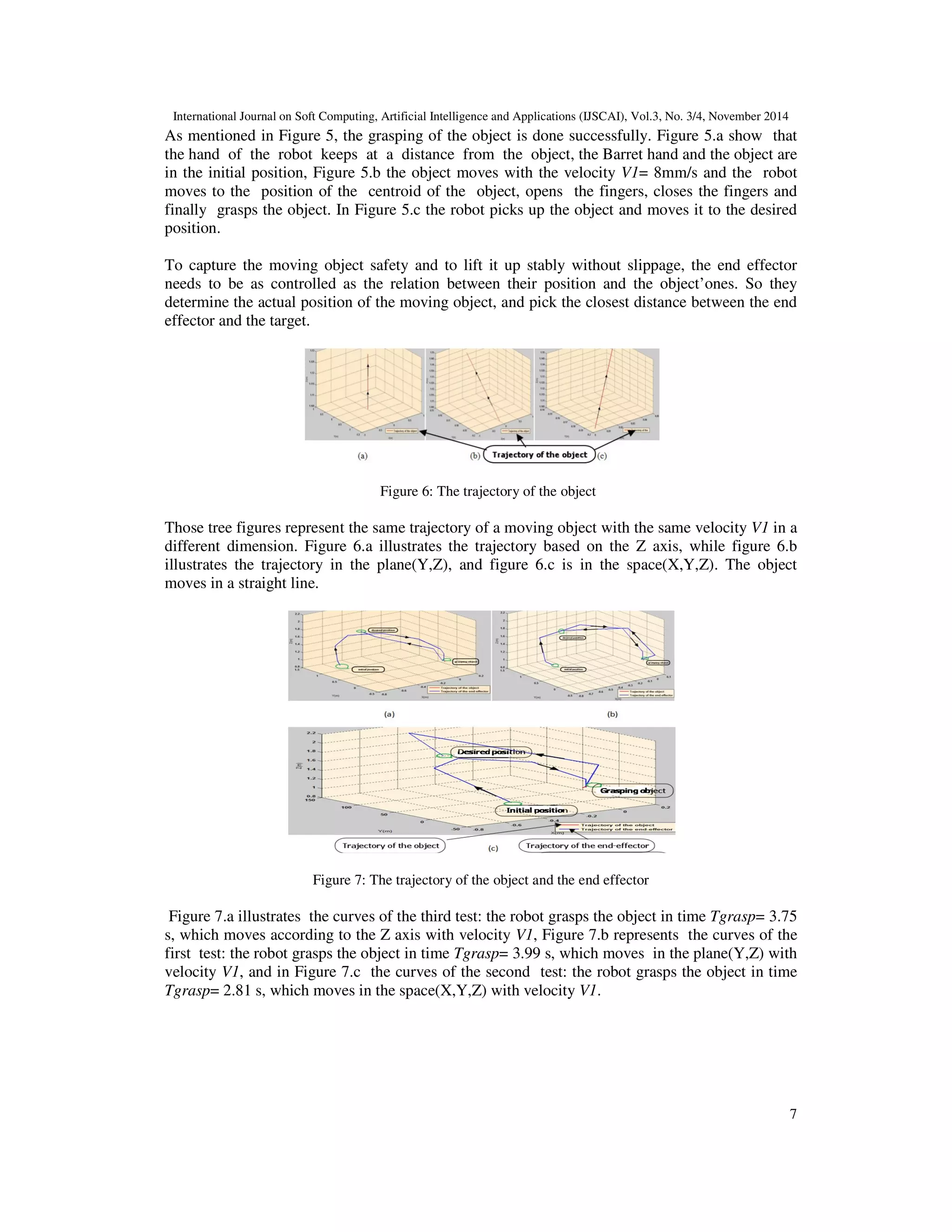
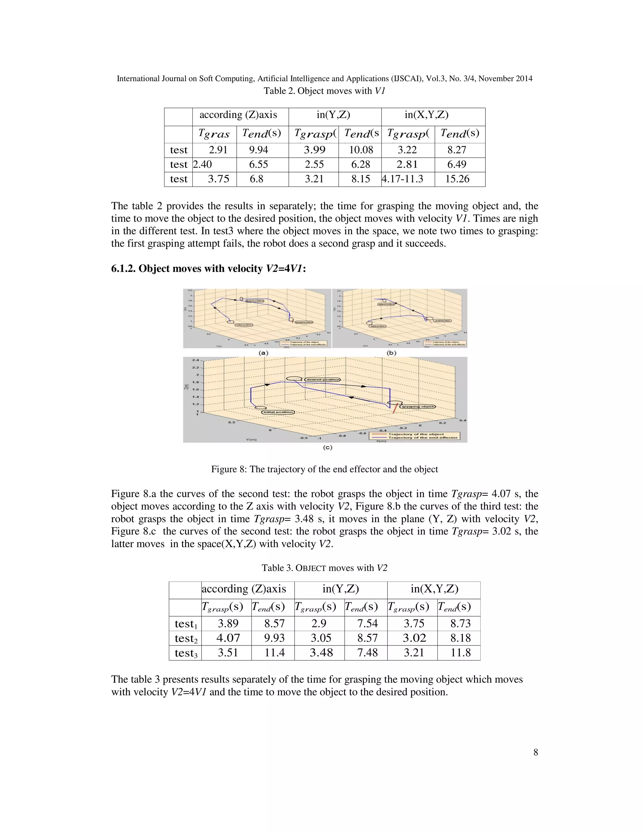
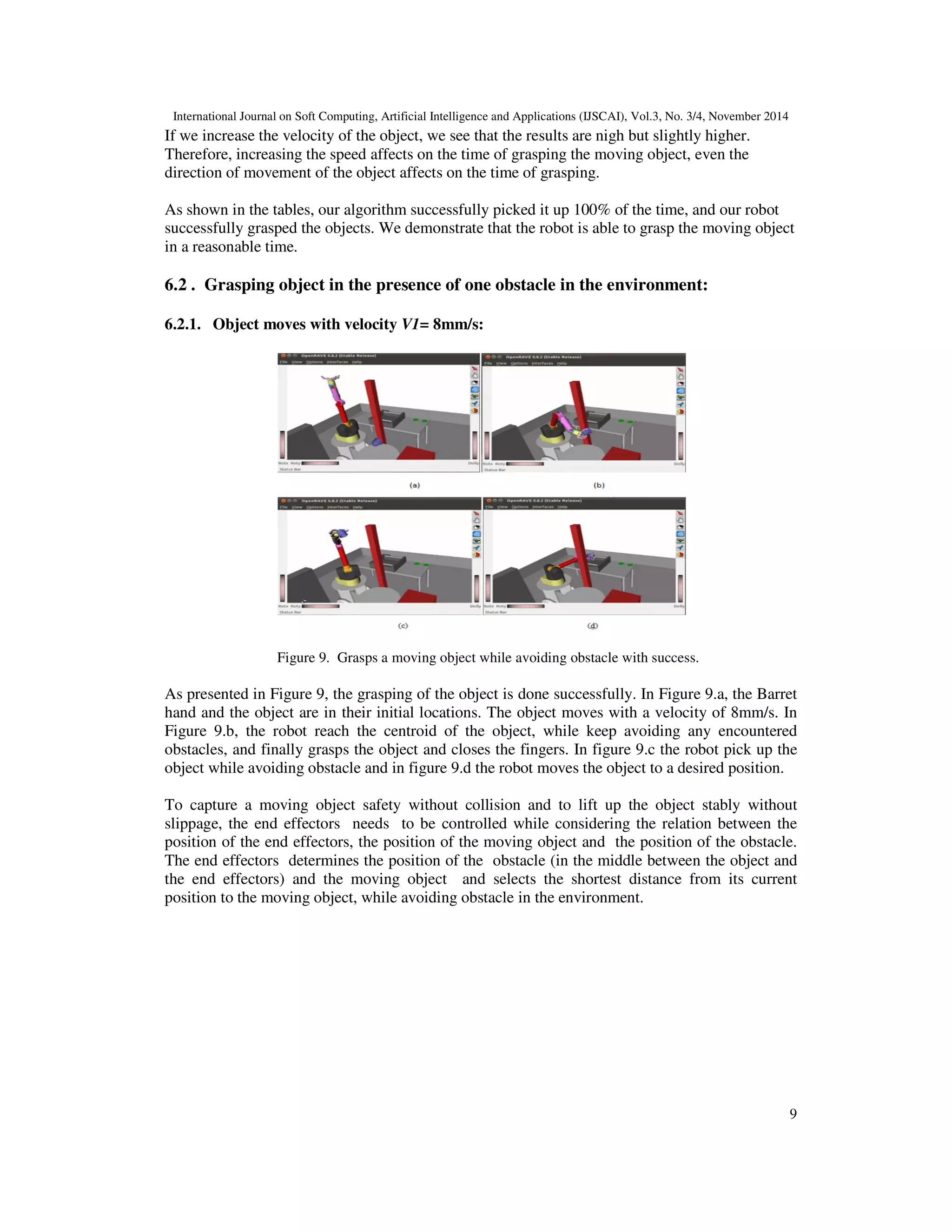
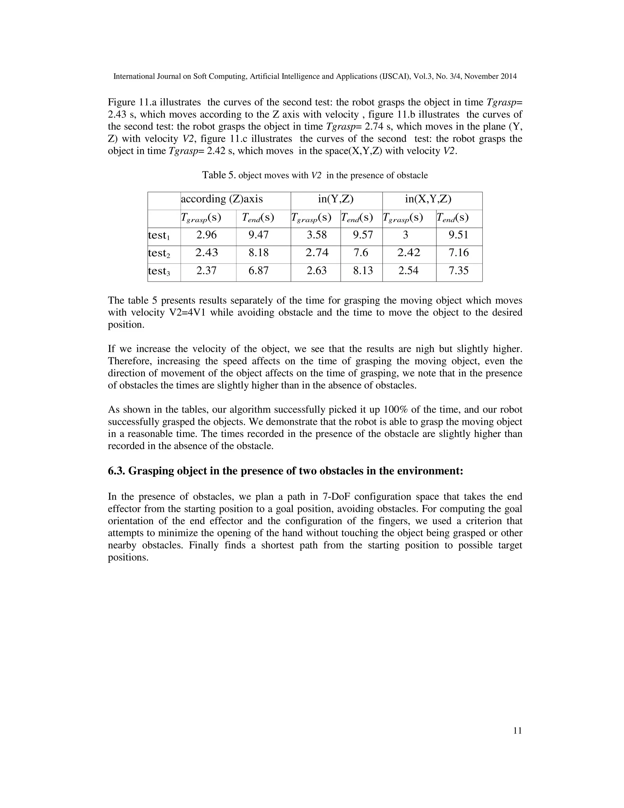
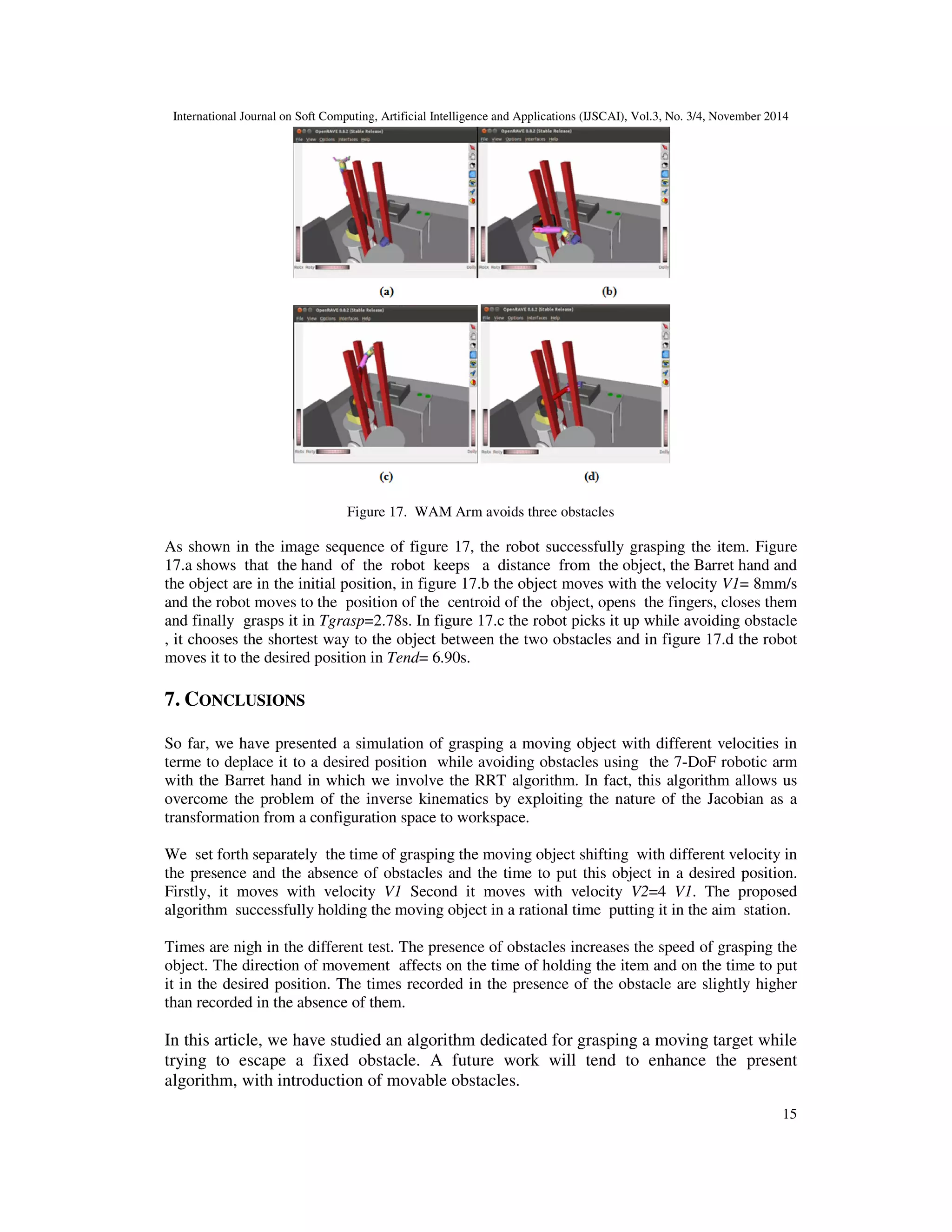
Many of the robotic grasping researches have been focusing on stationary objects. And for dynamic moving
objects, researchers have been using real time captured images to locate objects dynamically. However,
this approach of controlling the grasping process is quite costly, implying a lot of resources and image
processing.Therefore, it is indispensable to seek other method of simpler handling… In this paper, we are
going to detail the requirements to manipulate a humanoid robot arm with 7 degree-of-freedom to grasp
and handle any moving objects in the 3-D environment in presence or not of obstacles and without using
the cameras. We use the OpenRAVE simulation environment, as well as, a robot arm instrumented with the
Barrett hand. We also describe a randomized planning algorithm capable of planning. This algorithm is an
extent of RRT-JT that combines exploration, using a Rapidly-exploring Random Tree, with exploitation,
using Jacobian-based gradient descent, to instruct a 7-DoF WAM robotic arm, in order to grasp a moving
target, while avoiding possible encountered obstacles . We present a simulation of a scenario that starts
with tracking a moving mug then grasping it and finally placing the mug in a determined position, assuring
a maximum rate of success in a reasonable time.
Motion planning and controlling algorithm for grasping and manipulating movin...ijscai
Many of the robotic grasping researches have been focusing on stationary objects. And for dynamic moving
objects, researchers have been using real time captured images to locate objects dynamically. However,
this approach of controlling the grasping process is quite costly, implying a lot of resources and image
processing.Therefore, it is indispensable to seek other method of simpler handling… In this paper, we are
going to detail the requirements to manipulate a humanoid robot arm with 7 degree-of-freedom to grasp
and handle any moving objects in the 3-D environment in presence or not of obstacles and without using
the cameras. We use the OpenRAVE simulation environment, as well as, a robot arm instrumented with the
Barrett hand. We also describe a randomized planning algorithm capable of planning. This algorithm is an
extent of RRT-JT that combines exploration, using a Rapidly-exploring Random Tree, with exploitation,
using Jacobian-based gradient descent, to instruct a 7-DoF WAM robotic arm, in order to grasp a moving
target, while avoiding possible encountered obstacles . We present a simulation of a scenario that starts
with tracking a moving mug then grasping it and finally placing the mug in a determined position, assuring
a maximum rate of success in a reasonable time.
This paper describes a computer simulated artificial intelligence (AI) agent moving in 2D and 3D
environments. In the presented algorithm, the agent can take two operating modes: Manual Mode and Map
or Autopilot mode. The user can control the agent fully in a manual mode by moving it in all possible
directions depending on the environment. Obstacles are sensed by the agent from a certain distance and
are avoided accordingly. Another important mode is the Map mode. In this mode the user create a custom
map where initial position and a goal position are set. The user is able also to assign sudden and
predefined obstacles. By finding the shortest path, the agent moves to the goal position avoiding any
obstacles on its path.
The paper documents a set of algorithms that can help the agent to find the shortest path to a predefined
target location in a complex 3D environment, such as cities and mountains, avoiding all predefined and
sudden obstacles. These obstacles are avoided also in manual mode and the agent moves automatically to a
safe location. The implementation is based on the Hill Climbing algorithm (descent version), where the
agent finds its path to the global minimum (target goal). The Map generation algorithm, which is used to
assign costs to every location in the map, avoids a lot of the limitations of Hill Climbing.
A Path Planning Technique For Autonomous Mobile Robot Using Free-Configuratio...CSCJournals
This paper presents the implementation of a novel technique for sensor based path planning of autonomous mobile robots. The proposed method is based on finding free-configuration eigen spaces (FCE) in the robot actuation area. Using the FCE technique to find optimal paths for autonomous mobile robots, the underlying hypothesis is that in the low-dimensional manifolds of laser scanning data, there lies an eigenvector which corresponds to the free-configuration space of the higher order geometric representation of the environment. The vectorial combination of all these eigenvectors at discrete time scan frames manifests a trajectory, whose sum can be treated as a robot path or trajectory. The proposed algorithm was tested on two different test bed data, real data obtained from Navlab SLAMMOT and data obtained from the real-time robotics simulation program Player/Stage. Performance analysis of FCE technique was done with existing four path planning algorithms under certain working parameters, namely computation time needed to find a solution, the distance travelled and the amount of turning required by the autonomous mobile robot. This study will enable readers to identify the suitability of path planning algorithm under the working parameters, which needed to be optimized. All the techniques were tested in the real-time robotic software Player/Stage. Further analysis was done using MATLAB mathematical computation software.
Kinematics modeling of six degrees of freedom humanoid robot arm using impro...IJECEIAES
The robotic arm has functioned as an arm in the humanoid robot and is generally used to perform grasping tasks. Accordingly, kinematics modeling both forward and inverse kinematics is required to calculate the end-effector position in the cartesian space before performing grasping activities. This research presents the kinematics modeling of six degrees of freedom (6-DOF) robotic arm of the T-FLoW humanoid robot for the grasping mechanism of visual grasping systems on the robot operating system (ROS) platform and CoppeliaSim. Kinematic singularity is a common problem in the inverse kinematics model of robots, but. However, other problems are mechanical limitations and computational time. The work uses the homogeneous transformation matrix (HTM) based on the Euler system of the robot for the forward kinematics and demonstrates the capability of an improved damped least squares (I-DLS) method for the inverse kinematics. The I-DLS method was obtained by improving the original DLS method with the joint limits and clamping techniques. The I-DLS performs better than the original DLS during the experiments yet increases the calculation iteration by 10.95%, with a maximum error position between the endeffector and target positions in path planning of 0.1 cm.
Path Planning for Mobile Robot Navigation Using Voronoi Diagram and Fast Marc...Waqas Tariq
For navigation in complex environments, a robot needs to reach a compromise between the need for having efficient and optimized trajectories and the need for reacting to unexpected events. This paper presents a new sensor-based Path Planner which results in a fast local or global motion planning able to incorporate the new obstacle information. In the first step the safest areas in the environment are extracted by means of a Voronoi Diagram. In the second step the Fast Marching Method is applied to the Voronoi extracted areas in order to obtain the path. The method combines map-based and sensor-based planning operations to provide a reliable motion plan, while it operates at the sensor frequency. The main characteristics are speed and reliability, since the map dimensions are reduced to an almost unidimensional map and this map represents the safest areas in the environment for moving the robot. In addition, the Voronoi Diagram can be calculated in open areas, and with all kind of shaped obstacles, which allows to apply the proposed planning method in complex environments where other methods of planning based on Voronoi do not work.
Obstacle detection for autonomous systems using stereoscopic images and bacte...IJECEIAES
This paper presents a low cost strategy for real-time estimation of the position of ob- stacles in an unknown environment for autonomous robots. The strategy was intended for use in autonomous service robots, which navigate in unknown and dynamic indoor environments. In addition to human interaction, these environments are characterized by a design created for the human being, which is why our developments seek morphological and functional similarity equivalent to the human model. We use a pair of cameras on our robot to achieve a stereoscopic vision of the environment, and we analyze this information to determine the distance to obstacles using an algorithm that mimics bacterial behavior. The algorithm was evaluated on our robotic platform demonstrating high performance in the location of obstacles and real-time operation.
Design of Mobile Robot Navigation system using SLAM and Adaptive Tracking Con...iosrjce
IOSR Journal of Computer Engineering (IOSR-JCE) is a double blind peer reviewed International Journal that provides rapid publication (within a month) of articles in all areas of computer engineering and its applications. The journal welcomes publications of high quality papers on theoretical developments and practical applications in computer technology. Original research papers, state-of-the-art reviews, and high quality technical notes are invited for publications.
Mathematical modeling and kinematic analysis of 5 degrees of freedom serial l...IJECEIAES
Modeling and kinematic analysis are crucial jobs in robotics that entail identifying the position of the robot’s joints in order to accomplish particular tasks. This article uses an algebraic approach to model the kinematics of a serial link, 5 degrees of freedom (DOF) manipulator. The analytical method is compared to an optimization strategy known as sequential least squares programming (SLSQP). Using an Intel RealSense 3D camera, the colored object is picked up and placed using vision-based technology, and the pixel location of the object is translated into robot coordinates. The LOBOT LX15D serial bus servo controller was used to transmit these coordinates to the robotic arm. Python3 programming language was used throughout the entire analysis. The findings demonstrated that both analytical and optimized inverse kinematic solutions correctly identified colored objects and positioned them in their appropriate goal points.
This paper presents the design of an autonomous robot as a basic development of an intelligent wheeled mobile robot for air duct or corridor cleaning. The robot navigation is based on wall following algorithm. The robot is controlled us- ing fuzzy incremental controller (FIC) and embedded in PIC18F4550 microcontroller. FIC guides the robot to move along a wall in a desired direction by maintaining a constant distance to the wall. Two ultrasonic sensors are installed in the left side of the robot to sense the wall distance. The signals from these sensors are fed to FIC that then used to determine the speed control of two DC motors. The robot movement is obtained through differentiating the speed of these two motors. The experimental results show that FIC is successfully controlling the robot to follow the wall as a guidance line and has good performance compare with PID controller.
Wall follower autonomous robot development applying fuzzy incremental controllerrajabco
This paper presents the design of an autonomous robot as a basic development of an intelligent wheeled mobile robot for air duct or corridor cleaning. The robot navigation is based on wall following algorithm. The robot is controlled us- ing fuzzy incremental controller (FIC) and embedded in PIC18F4550 microcontroller. FIC guides the robot to move along a wall in a desired direction by maintaining a constant distance to the wall. Two ultrasonic sensors are installed in the left side of the robot to sense the wall distance. The signals from these sensors are fed to FIC that then used to de- termine the speed control of two DC motors. The robot movement is obtained through differentiating the speed of these two motors. The experimental results show that FIC is successfully controlling the robot to follow the wall as a guid- ance line and has good performance compare with PID controller.
High-Speed Neural Network Controller for Autonomous Robot Navigation using FPGAiosrjce
IOSR Journal of Electronics and Communication Engineering(IOSR-JECE) is a double blind peer reviewed International Journal that provides rapid publication (within a month) of articles in all areas of electronics and communication engineering and its applications. The journal welcomes publications of high quality papers on theoretical developments and practical applications in electronics and communication engineering. Original research papers, state-of-the-art reviews, and high quality technical notes are invited for publications.
Trajectory reconstruction for robot programming by demonstration IJECEIAES
The reproduction of hand movements by a robot remains difficult and conventional learning methods do not allow us to faithfully recreate these movements because it is very difficult when the number of crossing points is very large. Programming by Demonstration gives a better opportunity for solving this problem by tracking the user’s movements with a motion capture system and creating a robotic program to reproduce the performed tasks. This paper presents a Programming by Demonstration system in a trajectory level for the reproduction of hand/tool movement by a manipulator robot; this was realized by tracking the user’s movement with the ArToolkit and reconstructing the trajectories by using the constrained cubic spline. The results obtained with the constrained cubic spline were compared with cubic spline interpolation. Finally the obtained trajectories have been simulated in a virtual environment on the Puma 600 robot.
Smart element aware gate controller for intelligent wheeled robot navigationIJECEIAES
The directing of a wheeled robot in an unknown moving environment with physical barriers is a difficult proposition. In particular, having an optimal or near-optimal path that avoids obstacles is a major challenge. In this paper, a modified neuro-controller mechanism is proposed for controlling the movement of an indoor mobile robot. The proposed mechanism is based on the design of a modified Elman neural network (MENN) with an effective element aware gate (MEEG) as the neuro-controller. This controller is updated to overcome the rigid and dynamic barriers in the indoor area. The proposed controller is implemented with a mobile robot known as Khepera IV in a practical manner. The practical results demonstrate that the proposed mechanism is very efficient in terms of providing shortest distance to reach the goal with maximum velocity as compared with the MENN. Specifically, the MEEG is better than MENN in minimizing the error rate by 58.33%.
IEEE CASE 2016 On Avoiding Moving Objects for Indoor Autonomous QuadrotorsPeter SHIN
Abstract - A mini quadrotor can be used in many applica- tions, such as indoor airborne surveillance, payload delivery, and warehouse monitoring. In these applications, vision-based autonomous navigation is one of the most interesting research topics because precise navigation can be implemented based on vision analysis. However, pixel-based vision analysis approaches require a high-powered computer, which is inappropriate to be attached to a small indoor quadrotor. This paper proposes a method called the Motion-vector-based Moving Objects Detec- tion. This method detects and avoids obstacles using stereo motion vectors instead of individual pixels, thereby substan- tially reducing the data processing requirement. Although this method can also be used in the avoidance of stationary obstacles by taking into account the ego-motion of the quadrotor, this paper primarily focuses on providing our empirical verification on the real-time avoidance of moving objects.
Sachpazis:Terzaghi Bearing Capacity Estimation in simple terms with Calculati...Dr.Costas Sachpazis
Terzaghi's soil bearing capacity theory, developed by Karl Terzaghi, is a fundamental principle in geotechnical engineering used to determine the bearing capacity of shallow foundations. This theory provides a method to calculate the ultimate bearing capacity of soil, which is the maximum load per unit area that the soil can support without undergoing shear failure. The Calculation HTML Code included.
More Related Content
Similar to Motion Planning and Controlling Algorithm for Grasping and Manipulating Moving Objects in the Presence of Obstacles
Obstacle detection for autonomous systems using stereoscopic images and bacte...IJECEIAES
This paper presents a low cost strategy for real-time estimation of the position of ob- stacles in an unknown environment for autonomous robots. The strategy was intended for use in autonomous service robots, which navigate in unknown and dynamic indoor environments. In addition to human interaction, these environments are characterized by a design created for the human being, which is why our developments seek morphological and functional similarity equivalent to the human model. We use a pair of cameras on our robot to achieve a stereoscopic vision of the environment, and we analyze this information to determine the distance to obstacles using an algorithm that mimics bacterial behavior. The algorithm was evaluated on our robotic platform demonstrating high performance in the location of obstacles and real-time operation.
Design of Mobile Robot Navigation system using SLAM and Adaptive Tracking Con...iosrjce
IOSR Journal of Computer Engineering (IOSR-JCE) is a double blind peer reviewed International Journal that provides rapid publication (within a month) of articles in all areas of computer engineering and its applications. The journal welcomes publications of high quality papers on theoretical developments and practical applications in computer technology. Original research papers, state-of-the-art reviews, and high quality technical notes are invited for publications.
Mathematical modeling and kinematic analysis of 5 degrees of freedom serial l...IJECEIAES
Modeling and kinematic analysis are crucial jobs in robotics that entail identifying the position of the robot’s joints in order to accomplish particular tasks. This article uses an algebraic approach to model the kinematics of a serial link, 5 degrees of freedom (DOF) manipulator. The analytical method is compared to an optimization strategy known as sequential least squares programming (SLSQP). Using an Intel RealSense 3D camera, the colored object is picked up and placed using vision-based technology, and the pixel location of the object is translated into robot coordinates. The LOBOT LX15D serial bus servo controller was used to transmit these coordinates to the robotic arm. Python3 programming language was used throughout the entire analysis. The findings demonstrated that both analytical and optimized inverse kinematic solutions correctly identified colored objects and positioned them in their appropriate goal points.
This paper presents the design of an autonomous robot as a basic development of an intelligent wheeled mobile robot for air duct or corridor cleaning. The robot navigation is based on wall following algorithm. The robot is controlled us- ing fuzzy incremental controller (FIC) and embedded in PIC18F4550 microcontroller. FIC guides the robot to move along a wall in a desired direction by maintaining a constant distance to the wall. Two ultrasonic sensors are installed in the left side of the robot to sense the wall distance. The signals from these sensors are fed to FIC that then used to determine the speed control of two DC motors. The robot movement is obtained through differentiating the speed of these two motors. The experimental results show that FIC is successfully controlling the robot to follow the wall as a guidance line and has good performance compare with PID controller.
Wall follower autonomous robot development applying fuzzy incremental controllerrajabco
This paper presents the design of an autonomous robot as a basic development of an intelligent wheeled mobile robot for air duct or corridor cleaning. The robot navigation is based on wall following algorithm. The robot is controlled us- ing fuzzy incremental controller (FIC) and embedded in PIC18F4550 microcontroller. FIC guides the robot to move along a wall in a desired direction by maintaining a constant distance to the wall. Two ultrasonic sensors are installed in the left side of the robot to sense the wall distance. The signals from these sensors are fed to FIC that then used to de- termine the speed control of two DC motors. The robot movement is obtained through differentiating the speed of these two motors. The experimental results show that FIC is successfully controlling the robot to follow the wall as a guid- ance line and has good performance compare with PID controller.
High-Speed Neural Network Controller for Autonomous Robot Navigation using FPGAiosrjce
IOSR Journal of Electronics and Communication Engineering(IOSR-JECE) is a double blind peer reviewed International Journal that provides rapid publication (within a month) of articles in all areas of electronics and communication engineering and its applications. The journal welcomes publications of high quality papers on theoretical developments and practical applications in electronics and communication engineering. Original research papers, state-of-the-art reviews, and high quality technical notes are invited for publications.
Trajectory reconstruction for robot programming by demonstration IJECEIAES
The reproduction of hand movements by a robot remains difficult and conventional learning methods do not allow us to faithfully recreate these movements because it is very difficult when the number of crossing points is very large. Programming by Demonstration gives a better opportunity for solving this problem by tracking the user’s movements with a motion capture system and creating a robotic program to reproduce the performed tasks. This paper presents a Programming by Demonstration system in a trajectory level for the reproduction of hand/tool movement by a manipulator robot; this was realized by tracking the user’s movement with the ArToolkit and reconstructing the trajectories by using the constrained cubic spline. The results obtained with the constrained cubic spline were compared with cubic spline interpolation. Finally the obtained trajectories have been simulated in a virtual environment on the Puma 600 robot.
Smart element aware gate controller for intelligent wheeled robot navigationIJECEIAES
The directing of a wheeled robot in an unknown moving environment with physical barriers is a difficult proposition. In particular, having an optimal or near-optimal path that avoids obstacles is a major challenge. In this paper, a modified neuro-controller mechanism is proposed for controlling the movement of an indoor mobile robot. The proposed mechanism is based on the design of a modified Elman neural network (MENN) with an effective element aware gate (MEEG) as the neuro-controller. This controller is updated to overcome the rigid and dynamic barriers in the indoor area. The proposed controller is implemented with a mobile robot known as Khepera IV in a practical manner. The practical results demonstrate that the proposed mechanism is very efficient in terms of providing shortest distance to reach the goal with maximum velocity as compared with the MENN. Specifically, the MEEG is better than MENN in minimizing the error rate by 58.33%.
IEEE CASE 2016 On Avoiding Moving Objects for Indoor Autonomous QuadrotorsPeter SHIN
Abstract - A mini quadrotor can be used in many applica- tions, such as indoor airborne surveillance, payload delivery, and warehouse monitoring. In these applications, vision-based autonomous navigation is one of the most interesting research topics because precise navigation can be implemented based on vision analysis. However, pixel-based vision analysis approaches require a high-powered computer, which is inappropriate to be attached to a small indoor quadrotor. This paper proposes a method called the Motion-vector-based Moving Objects Detec- tion. This method detects and avoids obstacles using stereo motion vectors instead of individual pixels, thereby substan- tially reducing the data processing requirement. Although this method can also be used in the avoidance of stationary obstacles by taking into account the ego-motion of the quadrotor, this paper primarily focuses on providing our empirical verification on the real-time avoidance of moving objects.
Sachpazis:Terzaghi Bearing Capacity Estimation in simple terms with Calculati...Dr.Costas Sachpazis
Terzaghi's soil bearing capacity theory, developed by Karl Terzaghi, is a fundamental principle in geotechnical engineering used to determine the bearing capacity of shallow foundations. This theory provides a method to calculate the ultimate bearing capacity of soil, which is the maximum load per unit area that the soil can support without undergoing shear failure. The Calculation HTML Code included.
Overview of the fundamental roles in Hydropower generation and the components involved in wider Electrical Engineering.
This paper presents the design and construction of hydroelectric dams from the hydrologist’s survey of the valley before construction, all aspects and involved disciplines, fluid dynamics, structural engineering, generation and mains frequency regulation to the very transmission of power through the network in the United Kingdom.
Author: Robbie Edward Sayers
Collaborators and co editors: Charlie Sims and Connor Healey.
(C) 2024 Robbie E. Sayers
Student information management system project report ii.pdfKamal Acharya
Our project explains about the student management. This project mainly explains the various actions related to student details. This project shows some ease in adding, editing and deleting the student details. It also provides a less time consuming process for viewing, adding, editing and deleting the marks of the students.
About
Indigenized remote control interface card suitable for MAFI system CCR equipment. Compatible for IDM8000 CCR. Backplane mounted serial and TCP/Ethernet communication module for CCR remote access. IDM 8000 CCR remote control on serial and TCP protocol.
• Remote control: Parallel or serial interface.
• Compatible with MAFI CCR system.
• Compatible with IDM8000 CCR.
• Compatible with Backplane mount serial communication.
• Compatible with commercial and Defence aviation CCR system.
• Remote control system for accessing CCR and allied system over serial or TCP.
• Indigenized local Support/presence in India.
• Easy in configuration using DIP switches.
Technical Specifications
Indigenized remote control interface card suitable for MAFI system CCR equipment. Compatible for IDM8000 CCR. Backplane mounted serial and TCP/Ethernet communication module for CCR remote access. IDM 8000 CCR remote control on serial and TCP protocol.
Key Features
Indigenized remote control interface card suitable for MAFI system CCR equipment. Compatible for IDM8000 CCR. Backplane mounted serial and TCP/Ethernet communication module for CCR remote access. IDM 8000 CCR remote control on serial and TCP protocol.
• Remote control: Parallel or serial interface
• Compatible with MAFI CCR system
• Copatiable with IDM8000 CCR
• Compatible with Backplane mount serial communication.
• Compatible with commercial and Defence aviation CCR system.
• Remote control system for accessing CCR and allied system over serial or TCP.
• Indigenized local Support/presence in India.
Application
• Remote control: Parallel or serial interface.
• Compatible with MAFI CCR system.
• Compatible with IDM8000 CCR.
• Compatible with Backplane mount serial communication.
• Compatible with commercial and Defence aviation CCR system.
• Remote control system for accessing CCR and allied system over serial or TCP.
• Indigenized local Support/presence in India.
• Easy in configuration using DIP switches.
Welcome to WIPAC Monthly the magazine brought to you by the LinkedIn Group Water Industry Process Automation & Control.
In this month's edition, along with this month's industry news to celebrate the 13 years since the group was created we have articles including
A case study of the used of Advanced Process Control at the Wastewater Treatment works at Lleida in Spain
A look back on an article on smart wastewater networks in order to see how the industry has measured up in the interim around the adoption of Digital Transformation in the Water Industry.
Explore the innovative world of trenchless pipe repair with our comprehensive guide, "The Benefits and Techniques of Trenchless Pipe Repair." This document delves into the modern methods of repairing underground pipes without the need for extensive excavation, highlighting the numerous advantages and the latest techniques used in the industry.
Learn about the cost savings, reduced environmental impact, and minimal disruption associated with trenchless technology. Discover detailed explanations of popular techniques such as pipe bursting, cured-in-place pipe (CIPP) lining, and directional drilling. Understand how these methods can be applied to various types of infrastructure, from residential plumbing to large-scale municipal systems.
Ideal for homeowners, contractors, engineers, and anyone interested in modern plumbing solutions, this guide provides valuable insights into why trenchless pipe repair is becoming the preferred choice for pipe rehabilitation. Stay informed about the latest advancements and best practices in the field.
The Benefits and Techniques of Trenchless Pipe Repair.pdf
Motion Planning and Controlling Algorithm for Grasping and Manipulating Moving Objects in the Presence of Obstacles
1. International Journal on Soft Computing, Artificial Intelligence and Applications (IJSCAI), Vol.3, No. 3/4, November 2014
DOI :10.5121/ijscai.2014.3401 1
Motion Planning and Controlling Algorithm for
Grasping and Manipulating Moving Objects in the
Presence of Obstacles
Ali Chaabani1
, Mohamed Sahbi Bellamine2
and Moncef Gasmi3
1
National School of Engineering of Tunis, University of Manar, TUNISIA
2,3
Computer Laboratory for Industrial Systems, National Institute of Applied Sciences
and Technology, University of Carthage, TUNISIA
ABSRACT
Many of the robotic grasping researches have been focusing on stationary objects. And for dynamic moving
objects, researchers have been using real time captured images to locate objects dynamically. However,
this approach of controlling the grasping process is quite costly, implying a lot of resources and image
processing.Therefore, it is indispensable to seek other method of simpler handling… In this paper, we are
going to detail the requirements to manipulate a humanoid robot arm with 7 degree-of-freedom to grasp
and handle any moving objects in the 3-D environment in presence or not of obstacles and without using
the cameras. We use the OpenRAVE simulation environment, as well as, a robot arm instrumented with the
Barrett hand. We also describe a randomized planning algorithm capable of planning. This algorithm is an
extent of RRT-JT that combines exploration, using a Rapidly-exploring Random Tree, with exploitation,
using Jacobian-based gradient descent, to instruct a 7-DoF WAM robotic arm, in order to grasp a moving
target, while avoiding possible encountered obstacles . We present a simulation of a scenario that starts
with tracking a moving mug then grasping it and finally placing the mug in a determined position, assuring
a maximum rate of success in a reasonable time.
KEYWORDS
Grasping, moving object, trajectory planning , robot hand , obstacles.
1. INTRODUCTION
The problem of grasping a moving object in the presence of obstacles with a robotic manipulator
has been reported in different works. There have been many studies on grasping motion planning
for a manipulator to avoid obstacles [1], [2], [3]. One may want to apply a method used for
mobile robots, but it would cause a problem since it only focuses on grasping motion of robot
hands and since the configuration space dimension is too large. Motion planning for a
manipulator to avoid obstacles, however, which takes account of the interference between
machine joints and obstacles, has been extensively studied in recent years and now has reached a
practical level. Grasping operations in an environment with obstacles are now commonly
conducted in industrial applications and by service robots.
Many robotic applications have been designed to use the concept of “Planning Using Visual
Information”, i.e. control a given robot manipulator via a “servo loop” that use real world images
to take decisions [4], [5], [6]. At this point, the use of predictive algorithms, as the core of the
robot servo, tend to offer a better performance in the tracking and grasping process. [7]
2. International Journal on Soft Computing, Artificial Intelligence and Applications (IJSCAI), Vol.3, No. 3/4, November 2014
2
developed a system to grasp moving targets using a static camera and precalibrated camera-
manipulator transform. [8] proposed a control theory approach for grasping using visual
information. [9] presented a system to track and grasp an electric toy train moving in an
oval path using calibrated static stereo cameras.
The major challenges encountered within the visual servoing are mainly, how to reduce the robot
grasp response, considering the delay introduced by images processing, and who to resolve target
occlusion, when obstacles may obstruct the potential way to the object. Predictive algorithms
construct on of the best approaches to escape such performance limits, and ensuring a smart
tracking and grasping process. [10] use a prediction module which consists of a linear
predictor with the purpose of predicting the location that a moving object will have and
thus generate the control signal to move the eyes of a humanoid robot, which is capable
of using behavior models similar to those of human infants to track objects. [11] present a
tracking algorithm based on a linear prediction of second order solved by the Maximum
Entropy Method. It attempts to predict the centroid of the moving object in the next
frame, based on several past centroid measurements. [12] represent the tracked object as a
constellation of spatially localized linear predictors which are trained on a single image
sequence. In a learning stage, sets of pixels whose intensities allow for optimal prediction
of the transformations are selected as a support for the linear predictor . [13]
Implementation of tracking and capturing a moving object using a mobile robot.
The researchers who use the visual servoing system and the cameras for grasping moving object
find many difficulties to record images, to treat them, because of a lot computing and image
processing and also who use the predictive algorithms find a problem in the complexity of
algorithms witch based on many calculated and estimation[14]. In this research we want to grasp
a moving object with limited motion velocity. This can be done by determining desired position
for the object, the robot moves and aligns the end effector with the object and reaches towards it.
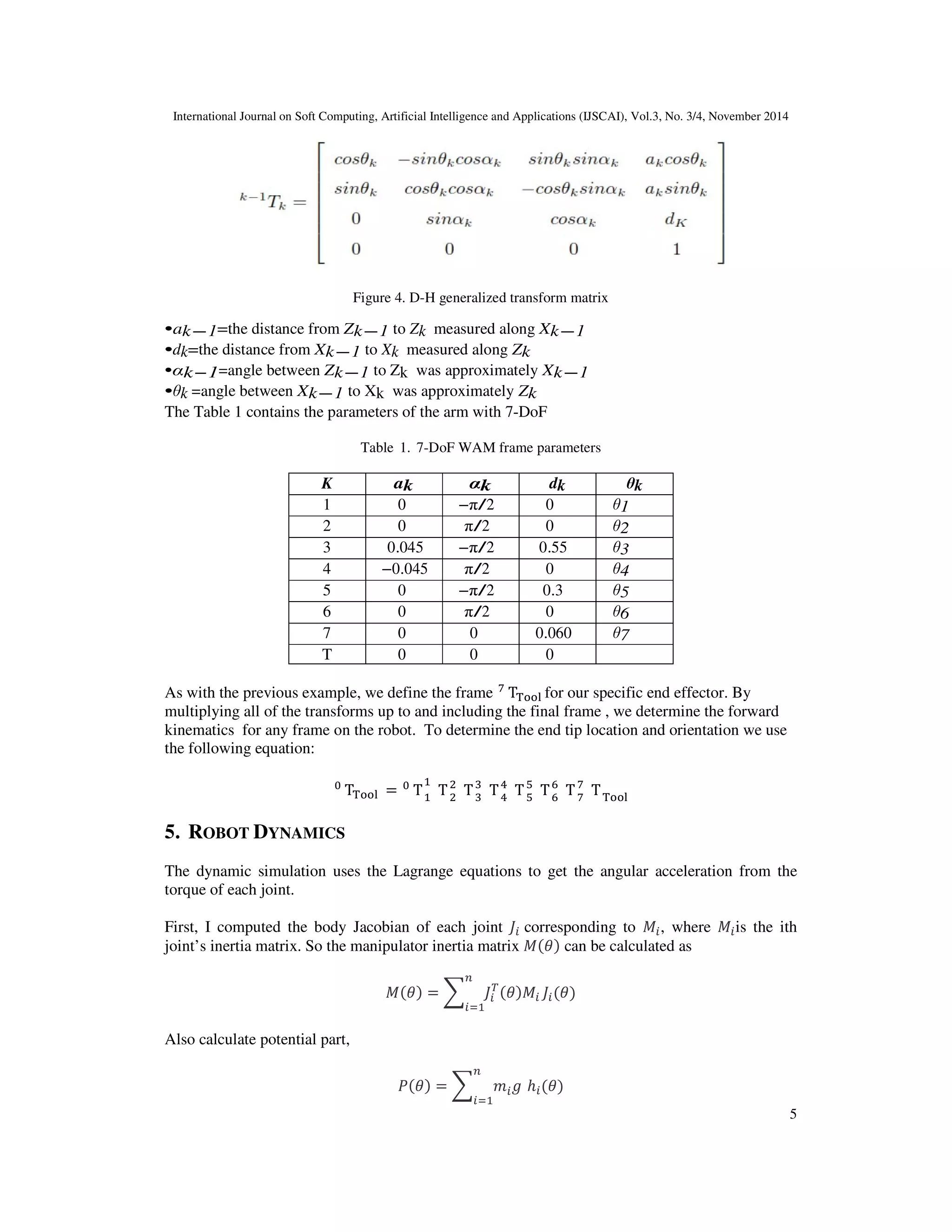
This paper presents a motion planning and controlling an arm of a humanoid robot for grasping
and manipulating of a moving object without cameras. We used an algorithm to control the end
effector pose (position and orientation) with respect to the pose of objects which can be moved in
the workspace of the robot. The proposed algorithm successfully grasped a moving object in a
reasonable time.
After introducing the grasp object problem, a discussion is made to distinguish the actual solution
among the others published in the literature. A description of the Rapidly-Exploring Random
Trees (RRT) is detailed in section 2. Then, in section 3, we give a brief overview of the transpose
of the Jacobian. The next section contains a description of the WAM™ arm. In Section 5
contains the Robot Dynamics. In Section 6, some results are given. Section 7 presents
conclusions drawn from this work.
2. RAPIDLY-EXPLORING RANDOM TREES (RRT)
In previous work [15],[16], approaching the motion planning problem was based on placing the
end effector at pre-configured locations, computed using the inverse kinematics(IK) applied to
some initial samples taken from the goal region. These locations are then set as goals for a
randomized planner, such as an RRT or BiRRT [17], [18]. The solution presented by this
approach remain unfinished because of the miss considered probabilistic aspect. The issue is that
the planner is forced to use numbers priori chosen from the goal regions.
Another way to tackle the grasp planning, certain types of workspace goals, is to explore the
configuration space of the robot with a heuristic search tree, and try to push the exploration
toward one goal region [19]. Nevertheless, the goal regions and heuristics presented in [20] are
3. International Journal on Soft Computing, Artificial Intelligence and Applications (IJSCAI), Vol.3, No. 3/4, November 2014
3
highly problem specific to generalize and tricky to adjust. Drumwright and Ng-Thow-Hing [21]
employ a similar strategy of extending toward a randomly-generated IK solution for a workspace
point. In [22], Vande Weghe et al. present the RRT-JT algorithm, which uses a forward-searching
tree to explore the C-space and a gradient-descent heuristic based on the Jacobian-transpose to
bias the tree toward a work-space goal point.
[23] present two probabilistically complete planners: an extension of RRT-JT, and a new
algorithm called IKBiRRT. Both algorithms function by interleaving exploration of the robot's C-
space with exploitation of WGRs(Workspace Goal Regions). The extended RRT-JT (Figure 2) is
designed for robots that do not have such algorithms and is able to combine the configuration
space exploration of RRTs with a workspace goal bias to produce direct paths through complex
environments extremely efficiently, without the need for any inverse kinematics.
Figure1. Configuration space(C-space)
3. USING THE JACOBIAN
Given a robot arm configuration q∈Q (the configuration space) and a desired end effector goal
xg∈X, where X is the space of end effector positions R3, we are interested in computing an
extension in configuration space from q to wards xg. Although the mapping from Q to X is often
nonlinear and hence expensive to deduct, its derivative the Jacobian,is a linear map from the
tangent space of Q to that of X, that can be computed easily (Jq˙=ẋ , where x∈X is the end
effector position (or pose) corresponding to q). Ideally, to drive the end effector to a desired
configuration xg, (d xg /dt≈0: object moves slowly) we could compute the error e(t)=( xg −x) and
run a controller of the form q˙=KJ−1e, where K is a positive gain. This simple controller is
capable to attain the target without considering any possible barriers or articulation limits.
However this turn into a complex controller, where the inverse of the Jacobian must be done at
each time step. To escape this expensive approach, we use alternatively the transpose of the
Jacobian and the control law fall into the form of q˙=KJTe. The controller eliminates the large
overhead of computing the inverse by using the easy-to-compute Jacobian instead. It is easy to
show that, under the same obstacle-free requirements as the Jacobian inverse controller, the
Jacobian transpose(JT) controller is also guaranteed to reach the goal. The instantaneous motion
of the end effector is given by ẋ =Jq˙ =J(KJTe). The inner product of this Instantaneous motion
with the error vector is given by eTẋ = keTJJTe ≥ 0. As this is always positive, under our
assumptions with obstacles, we may ensure that the controller will be able to make onward
progress towards the target[24].
4. International Journal on Soft Computing, Artificial Intelligence and Applications (IJSCAI), Vol.3, No. 3/4, November 2014
4
Figure 2. Depiction of the RRT-JT algorithm searching in C-space: from the start configuration to (WGRs).
The forward-searching tree is shown with green nodes, the blue regions are obstacles, [14].
4. THE WAM™ ARM
The WAM arm is a robotic back drivable manipulator. It has a stable joint-torque control with a
direct-drive capability. It offers a zero backslash and near zero friction to enhance the
performance of today’s robots. It comes with three main variants 4-DoF, 7- DoF, both with
human-like kinematics, and 4-DoF with 3-DoF Gimbals. Its articulation ranges go beyond those
for conventional robotic arms [25].
We use WAM 7-DoF Arm with attached Barrett Hand.
Figure 3. WAM 7-DoF dimensions and D-H frames, [26].
Figure 3. presents the whole 7-DoF WAM system in the initial position. A positive joint motion
is on the right hand rule, for each axis.The following equation of homogeneous transformation in
Figure 4 is used to determine the transformation between the axes K and K-1.
5. International Journal on Soft Computing, Artificial Intelligence and Applications (IJSCAI), Vol.3, No. 3/4, November 2014
5
Figure 4. D-H generalized transform matrix
•ak−1=the distance from Zk−1 to Zk measured along Xk−1
•dk=the distance from Xk−1 to Xk measured along Zk
•αk−1=angle between Zk−1 to Zk was approximately Xk−1
•θk =angle between Xk−1 to Xk was approximately Zk
The Table 1 contains the parameters of the arm with 7-DoF
Table 1. 7-DoF WAM frame parameters
K ak αk dk θk
1 0 −π/2 0 θ1
2 0 π/2 0 θ2
3 0.045 −π/2 0.55 θ3
4 −0.045 π/2 0 θ4
5 0 −π/2 0.3 θ5
6 0 π/2 0 θ6
7 0 0 0.060 θ7
T 0 0 0
As with the previous example, we define the frame
T for our specific end effector. By
multiplying all of the transforms up to and including the final frame , we determine the forward
kinematics for any frame on the robot. To determine the end tip location and orientation we use
the following equation:
T =
T
T
T
T
6.
7. T
T
T
T
5. ROBOT DYNAMICS
The dynamic simulation uses the Lagrange equations to get the angular acceleration from the
torque of each joint.
First, I computed the body Jacobian of each joint corresponding to , where is the ith
joint’s inertia matrix. So the manipulator inertia matrix can be calculated as
=
Also calculate potential part,
=
ℎ
8. International Journal on Soft Computing, Artificial Intelligence and Applications (IJSCAI), Vol.3, No. 3/4, November 2014
6
Second, I computed the torques of each joint using Lagrange equation, which is,
!
−
= #
where τ represents the torque of the joint and,
$, ! =
1
2
!
! −
After expanding the components of the equation, the equation is as following:
) + +$, !
! + ,$, ! = #
where +$, ! is the Coriolis and centrifugal force term and ,$, ! is the gravity term and
= -
9. .T
and
! =
23
24
,
) =
253
245 .
6. RESULTS AND ANALYSIS
To demonstrate and illustrate the proposed procedure, we present an example which the robot is
equipped with a 7-DoF arm (see Figure 3) and a three-fingered Barrett hand(in fact in each time
there are three tests: test1, test2 and test3 ). The goal is to follow a moving model mug, stably
holding it, pick it up and move it to the desired position while avoiding the existing obstacles. The
mug was moving in a straight line trajectory in the space with velocity range 8-32 mm/s. The
initial positions of the end effector were (-0.730m,0.140m ,2.168m) and those of the moving
object were (-0.005m,-0.200m ,1.105m). In order to grasp the moving object stably and move it,
the robot hand reaches the object than it closes its fingers.
6.1. Grasping object in the environment without obstacles
6.1.1. Object moves with velocity V1= 8mm/s:
The transformation equations used to update the manipulator's joints until the distance between
the end effector and the moving object almost equal to zero. Once the position of the contact is
achieved, the Barret hand closes its fingers and grasps the object.
Figure 5: Successful grasping of a moving object
10. International Journal on Soft Computing, Artificial Intelligence and Applications (IJSCAI), Vol.3, No. 3/4, November 2014
7
As mentioned in Figure 5, the grasping of the object is done successfully. Figure 5.a show that
the hand of the robot keeps at a distance from the object, the Barret hand and the object are
in the initial position, Figure 5.b the object moves with the velocity V1= 8mm/s and the robot
moves to the position of the centroid of the object, opens the fingers, closes the fingers and
finally grasps the object. In Figure 5.c the robot picks up the object and moves it to the desired
position.
To capture the moving object safety and to lift it up stably without slippage, the end effector
needs to be as controlled as the relation between their position and the object’ones. So they
determine the actual position of the moving object, and pick the closest distance between the end
effector and the target.
Figure 6: The trajectory of the object
Those tree figures represent the same trajectory of a moving object with the same velocity V1 in a
different dimension. Figure 6.a illustrates the trajectory based on the Z axis, while figure 6.b
illustrates the trajectory in the plane(Y,Z), and figure 6.c is in the space(X,Y,Z). The object
moves in a straight line.
Figure 7: The trajectory of the object and the end effector
Figure 7.a illustrates the curves of the third test: the robot grasps the object in time Tgrasp= 3.75
s, which moves according to the Z axis with velocity V1, Figure 7.b represents the curves of the
first test: the robot grasps the object in time Tgrasp= 3.99 s, which moves in the plane(Y,Z) with
velocity V1, and in Figure 7.c the curves of the second test: the robot grasps the object in time
Tgrasp= 2.81 s, which moves in the space(X,Y,Z) with velocity V1.
11. International Journal on Soft Computing, Artificial Intelligence and Applications (IJSCAI), Vol.3, No. 3/4, November 2014
8
Table 2. Object moves with V1
according (Z)axis in(Y,Z) in(X,Y,Z)
Tgras
p(s)
Tend(s) Tgrasp(
s)
Tend(s
)
Tgrasp(
s)
Tend(s)
test
1
2.91 9.94 3.99 10.08 3.22 8.27
test
2
2.40 6.55 2.55 6.28 2.81 6.49
test
3
3.75 6.8 3.21 8.15 4.17-11.3 15.26
The table 2 provides the results in separately; the time for grasping the moving object and, the
time to move the object to the desired position, the object moves with velocity V1. Times are nigh
in the different test. In test3 where the object moves in the space, we note two times to grasping:
the first grasping attempt fails, the robot does a second grasp and it succeeds.
6.1.2. Object moves with velocity V2=4V1:
Figure 8: The trajectory of the end effector and the object
Figure 8.a the curves of the second test: the robot grasps the object in time Tgrasp= 4.07 s, the
object moves according to the Z axis with velocity V2, Figure 8.b the curves of the third test: the
robot grasps the object in time Tgrasp= 3.48 s, it moves in the plane (Y, Z) with velocity V2,
Figure 8.c the curves of the second test: the robot grasps the object in time Tgrasp= 3.02 s, the
latter moves in the space(X,Y,Z) with velocity V2.
Table 3. OBJECT moves with V2
according (Z)axis in(Y,Z) in(X,Y,Z)
Tgrasp(s) Tend(s) Tgrasp(s) Tend(s) Tgrasp(s) Tend(s)
test1 3.89 8.57 2.9 7.54 3.75 8.73
test2 4.07 9.93 3.05 8.57 3.02 8.18
test3 3.51 11.4 3.48 7.48 3.21 11.8
The table 3 presents results separately of the time for grasping the moving object which moves
with velocity V2=4V1 and the time to move the object to the desired position.
12. International Journal on Soft Computing, Artificial Intelligence and Applications (IJSCAI), Vol.3, No. 3/4, November 2014
9
If we increase the velocity of the object, we see that the results are nigh but slightly higher.
Therefore, increasing the speed affects on the time of grasping the moving object, even the
direction of movement of the object affects on the time of grasping.
As shown in the tables, our algorithm successfully picked it up 100% of the time, and our robot
successfully grasped the objects. We demonstrate that the robot is able to grasp the moving object
in a reasonable time.
6.2 . Grasping object in the presence of one obstacle in the environment:
6.2.1. Object moves with velocity V1= 8mm/s:
Figure 9. Grasps a moving object while avoiding obstacle with success.
As presented in Figure 9, the grasping of the object is done successfully. In Figure 9.a, the Barret
hand and the object are in their initial locations. The object moves with a velocity of 8mm/s. In
Figure 9.b, the robot reach the centroid of the object, while keep avoiding any encountered
obstacles, and finally grasps the object and closes the fingers. In figure 9.c the robot pick up the
object while avoiding obstacle and in figure 9.d the robot moves the object to a desired position.
To capture a moving object safety without collision and to lift up the object stably without
slippage, the end effectors needs to be controlled while considering the relation between the
position of the end effectors, the position of the moving object and the position of the obstacle.
The end effectors determines the position of the obstacle (in the middle between the object and
the end effectors) and the moving object and selects the shortest distance from its current
position to the moving object, while avoiding obstacle in the environment.
13. International Journal on Soft Computing, Artificial Intelligence and Applications (IJSCAI), Vol.3, No. 3/4, November 2014
10
Figure 10. The trajectory of the end effector and the object
Figure 10.a illustrates the curves of the first test: the robot grasps the object in time Tgrasp= 2.45
s, which moves according to the Z axis with velocity V1, figure 10.b illustrates the curves of the
third test: the robot grasps the object in time Tgrasp= 3.03 s, which moves in the plane(Y,Z)
with velocity V1, figure 10.c illustrates the curves of the second test: the robot grasps the object
in time Tgrasp= 2.91 s, which moves in the space(X,Y,Z) with velocity V1.
Table 4.object moves with V1 in the presence of obstacle
according
(Z)axis
in(Y,Z) in(X,Y,Z)
Tgras
p(s)
Tend(s
)
Tgrasp
(s)
Tend(s
)
Tgrasp
(s)
Tend(s
)
test1 2.45 8.91 3.11 7.63 5.16 11.38
test2 2.95 9.08 2.83 9.33 2.91 7.07
test3 3.18 9.74 3.03 7.6 4.24 8.77
The table 4 presents results separately of the time for grasping the moving object which moves
with velocity V1 while avoiding obstacle, and the time to move the object to the desired position.
Times are nigh in the different test. The direction of movement of the object affects on the time
grasping (Tgrasp) and on the time to move the object to desired position (Tend).
6.2.2. Object moves with velocity V2=4V1:
Figure 11. The trajectory of the end effector and the object
14. International Journal on Soft Computing, Artificial Intelligence and Applications (IJSCAI), Vol.3, No. 3/4, November 2014
11
Figure 11.a illustrates the curves of the second test: the robot grasps the object in time Tgrasp=
2.43 s, which moves according to the Z axis with velocity , figure 11.b illustrates the curves of
the second test: the robot grasps the object in time Tgrasp= 2.74 s, which moves in the plane (Y,
Z) with velocity V2, figure 11.c illustrates the curves of the second test: the robot grasps the
object in time Tgrasp= 2.42 s, which moves in the space(X,Y,Z) with velocity V2.
Table 5. object moves with V2 in the presence of obstacle
according (Z)axis in(Y,Z) in(X,Y,Z)
Tgrasp(s) Tend(s) Tgrasp(s) Tend(s) Tgrasp(s) Tend(s)
test1 2.96 9.47 3.58 9.57 3 9.51
test2 2.43 8.18 2.74 7.6 2.42 7.16
test3 2.37 6.87 2.63 8.13 2.54 7.35
The table 5 presents results separately of the time for grasping the moving object which moves
with velocity V2=4V1 while avoiding obstacle and the time to move the object to the desired
position.
If we increase the velocity of the object, we see that the results are nigh but slightly higher.
Therefore, increasing the speed affects on the time of grasping the moving object, even the
direction of movement of the object affects on the time of grasping, we note that in the presence
of obstacles the times are slightly higher than in the absence of obstacles.
As shown in the tables, our algorithm successfully picked it up 100% of the time, and our robot
successfully grasped the objects. We demonstrate that the robot is able to grasp the moving object
in a reasonable time. The times recorded in the presence of the obstacle are slightly higher than
recorded in the absence of the obstacle.
6.3. Grasping object in the presence of two obstacles in the environment:
In the presence of obstacles, we plan a path in 7-DoF configuration space that takes the end
effector from the starting position to a goal position, avoiding obstacles. For computing the goal
orientation of the end effector and the configuration of the fingers, we used a criterion that
attempts to minimize the opening of the hand without touching the object being grasped or other
nearby obstacles. Finally finds a shortest path from the starting position to possible target
positions.
15. International Journal on Soft Computing, Artificial Intelligence and Applications (IJSCAI), Vol.3, No. 3/4, November 2014
12
6.3.1. Two obstacles between the object and the desired position(see Figure 12):
Figure 12. Two obstacles between the object and the desired position
The presence of two obstacles between the object and the desired position affects on the time to
move the object to the desired position.
Figure 13. The trajectory of the end effector and the object while avoiding two obstacles between the object
and the desired position
Figure 13.a illustrates the curves of the second test: the robot grasps the object in time Tgrasp=
3.67 s and Tend= 8.99 s, which moves according to the Z axis with velocity V2, figure 13.b
illustrates the curves of the second test: the robot grasps the object in time Tgrasp= 2.93 s and
Tend= 8.83 s, which moves in the plane (Y, Z) with velocity V2, figure 13.c illustrates the
curves of the second test: the robot grasps the object in time Tgrasp= 3.12 s and Tend= 10.62 s,
which moves in the space(X,Y,Z) with velocity V2.
16. International Journal on Soft Computing, Artificial Intelligence and Applications (IJSCAI), Vol.3, No. 3/4, November 2014
13
6.3.2. Two obstacles between the arm and the object(see Figure 14):
Figure 14. Two obstacles between the arm and the object
The presence of two obstacles between the arm and the object affects on the time to grasp the
moving object.
Figure 15. The trajectory of the end effector and the object while avoiding two obstacles between the arm
and the object
Figure 15.a illustrates the curves of the second test: the robot grasps the object in time Tgrasp=
3.21 s and Tend= 7.93 s, which moves according to the Z axis with velocity V2, figure 15.b
illustrates the curves of the second test: the robot grasps the object in time Tgrasp= 3.37 s and
Tend= 8.98 s, which moves in the plane (Y, Z) with velocity V2, figure 15.c illustrates the curves
of the second test: the robot grasps the object in time Tgrasp= 3.47 s and Tend= 7.50 s, which
moves in the space(X,Y,Z) with velocity V2.
17. International Journal on Soft Computing, Artificial Intelligence and Applications (IJSCAI), Vol.3, No. 3/4, November 2014
14
6.4. Grasping object in the presence of three obstacles in the environment:
Figure 16. WAM Arm avoids three obstacles
In figure 16, the robot successfully grasping the item. Figure 16.a shows that the hand of the
robot keeps a distance from the object, the Barret hand and the object are in the initial
position, in figure 16.b the object moves with the velocity V1= 8mm/s and the robot moves to the
position of the centroid of the object, it chooses the shortest way to the object between the two
obstacles, opens the fingers, closes them and finally grasps it in Tgrasp=2.46s. In figure 16.c the
robot picks it up while avoiding obstacle and in figure 16.d the robot moves it to the desired
position in Tend= 6.68s.
Table 6. Object moves with V1 in the presence of three obstacles
according (Z) axis in(Y,Z) in(X,Y,Z)
Tgrasp(s) Tend(s) Tgrasp(s) Tend(s) Tgrasp(s) Tend(s)
test1 2.38 7.14 3.20 8.43 2.88 9.08
test2 2.56 7.88 2.50 7.30 2.46 6.68
test3 2.13 7.20 2.50 8.20 2.67 7.04
The table 6 presents results of the time for grasping the moving object which moves with velocity
V1 while avoiding three obstacles and the time to move it to the desired position.
If we increase the number of the obstacles, the time of grasping the object was reduced. The
choice of the trajectory by the robot is reduced. The robot chooses the shortest trajectory to the
object.
18. International Journal on Soft Computing, Artificial Intelligence and Applications (IJSCAI), Vol.3, No. 3/4, November 2014
15
Figure 17. WAM Arm avoids three obstacles
As shown in the image sequence of figure 17, the robot successfully grasping the item. Figure
17.a shows that the hand of the robot keeps a distance from the object, the Barret hand and
the object are in the initial position, in figure 17.b the object moves with the velocity V1= 8mm/s
and the robot moves to the position of the centroid of the object, opens the fingers, closes them
and finally grasps it in Tgrasp=2.78s. In figure 17.c the robot picks it up while avoiding obstacle
, it chooses the shortest way to the object between the two obstacles and in figure 17.d the robot
moves it to the desired position in Tend= 6.90s.
7. CONCLUSIONS
So far, we have presented a simulation of grasping a moving object with different velocities in
terme to deplace it to a desired position while avoiding obstacles using the 7-DoF robotic arm
with the Barret hand in which we involve the RRT algorithm. In fact, this algorithm allows us
overcome the problem of the inverse kinematics by exploiting the nature of the Jacobian as a
transformation from a configuration space to workspace.
We set forth separately the time of grasping the moving object shifting with different velocity in
the presence and the absence of obstacles and the time to put this object in a desired position.
Firstly, it moves with velocity V1 Second it moves with velocity V2=4 V1. The proposed
algorithm successfully holding the moving object in a rational time putting it in the aim station.
Times are nigh in the different test. The presence of obstacles increases the speed of grasping the
object. The direction of movement affects on the time of holding the item and on the time to put
it in the desired position. The times recorded in the presence of the obstacle are slightly higher
than recorded in the absence of them.
In this article, we have studied an algorithm dedicated for grasping a moving target while
trying to escape a fixed obstacle. A future work will tend to enhance the present
algorithm, with introduction of movable obstacles.
19. International Journal on Soft Computing, Artificial Intelligence and Applications (IJSCAI), Vol.3, No. 3/4, November 2014
16
REFERENCES
[1] F.Ruggiero,Grasp and manipulation of objects with am ulti-fingered hand in unstructured
environments ,Ph.D.Thesis, UNIVERSITA DEGLISTUDI DI NAPOLI (2010).
[2] T.Adam Leper, Kayden Hsiao, Strategies for human-in-the-loop robotic grasping, Robot
Manipulation and Programming (2012).
[3] K.Nagase,Y.Aiyana,Grasp motion planning with redundant dof of grasping pose, Journal of Robotics
and Mechatronics Vol.25No.3 (2013).
[4] H. Faster, A robot ping pong player: optimized mechanics, high performance 3dvision, and
intelligent sensor control, Robotersystemepp. 161170 (1990).
[5] M.-S.Kim, Robot visual servo through trajectory estimation of amoving object using kalman filter
emerging intelligent computing technology and applications,D.-S.Huang, etal.,Eds., ed: Springer
Berlin /Heidel- bergvol.5754(2009)pp.1122–1130.
[6] F.Husain, Real time tracking and grasping of a moving object from range video(2013).
[7] N.Hushing, Control of a robotic manipulator to grasp a moving tar- get using vision,.IEEE Int.
Conf.Robotics and Automation (1990)604-609.
[8] A. Kiva, on adaptive vision feed back control of robotic manipulators, in: Proc. IEEE Conf. Decision
and Control2,1991,pp.1883–1888.
[9] B.M.. .J. Canny., Easily computable optimum grasps in2-dand 3-d,In Proc. IEEE International
Conference on Robotics and Automation (1994) pages739–747.
[10] J.B.Balkenius, C., Event prediction and object motion estimation in the development of visual
attention, Proceedings of the Fifth International Workshop on Epigenetic (2005).
[11] A.-B. S.Yeoh, P., Accurate real-time object tracking with linear predic- tion method, Proceedings of
International Conferenceon Image Processing Volume3 (2003).
[12] Z.-K.Matas, J., Learning efficient linear predictors for motion estimation, Proceedings of 5 Indian
Conference on Computer Vision, Graphics and Image Processing, Springer-Verlag, Madurai, India
(2006).
[13] J.-w. P. Sang-joo Kim, J. Lee., Implementation of tracking and capturing a moving object using a
mobile robot, International journal of control automation and systems 3(2005)444.
[14] D. Berenson, Manipulation Planning with Workspace Goal Regions, The Robotics Institute, Carnegie
Mellon University, USA (2009).
[15] J. K. M. Stilman, J.-U. Schamburek,T. Asfour, Manipulation planning among movable obstacles, in
IROS (2007).
[16] K.K.Y.Hirano, S.Yoshizawa, Image-based object recognition and dexteroushand/arm motion
planning using rrts for grasping in cluttered scene, in IROS (2005).
[17] S. LaValle, J. Kuffner, Rapidly-exploring random trees: Progress and prospects, in WAFR
(2000).
[18] S.M. LaValle, Planning algorithms, Cambridge, U.K.: Cambridge University Press, available at
http://planning.cs.uiuc.edu/(2006).
[19] R.D.D.Bertram, J.Kuffner, T.Asfour, An integrated approach to inverse kinematics and path planning
for redundant manipulators, in ICRA (2006).
[20] E. Drumwright, V.Ng-Thow-Hing, Toward interactive reaching in static environments for humanoid
robots, in Proc.IEEE/RSJ International Conference on Intelligent Robots and Systems
(2006)pp.846–851.
[21] D.F.M. Vande Weghe, S.Srinivasa, Randomized path planning forredundant manipulators with out
inverse kinematics, in Humanoids (2007).
[22] S.S.S.Dmitry Berenson, Pittsburgh and by the National Science Founda- tionunder GrantNo.EEC-
0540865 (2009).
[23] M.V.Weghe, Randomized path planning for redundant manipulators with- out inverse kinematics.
[24] E.L.Damian, Grasp planning for object manipulation by an autonomous robot, Master’s thesis,
National Institute of Applied Sciences of T oulouze (2006).
[25] M.W.Spong,M.Vidyasagar, Robot dynamics and control (1989).
[26] WAM Arm User’s Guide, www.barrett.com
20. International Journal on Soft Computing, Artificial Intelligence and Applications (IJSCAI), Vol.3, No. 3/4, November 2014
17
Authors
Ali CHAABANI was born in Kairouan,Tunisia, in 1987. He received, from the Sfax
National School of Engineering (ENIS), the Principal Engineering Diploma in
Computer science in 2011, from the National Institute of Applied Sciences and
Technology (INSAT) the Master of Computer science and Automation in 2013.Now,
he is a PhD student in Tunis National School of Engineering (ENIT) and researcher in
Informatics Laboratory for Industrial Systems (LISI) at the National Institute of
Applied Sciences and Technology (INSAT).
Mohamed Sahbi BELLAMINE is an assistant professor in the National Institute of
Applied Sciences and Technology, University of Carthage. He is a member of
Laboratory of Computer Science of Industrials Systems (LISI). His domain of interests
is Human-Robot Interaction, Social Sociable robots.
Moncef GASMI was born in Tunis,Tunisia, in 1958. He received the Principal
Engineering Diploma in Electrical Engineering in 1984 from the Tunis National School
of Engineering (ENIT), the Master of Systems Analysis and Computational Treatment
in 1985, the Doctorate in Automatic Control in 1989 and the State Doctorate in
Electrical Engineering in 2001. Now, he teach as a Professor and Director of the
Informatics Laboratory for Industrial Systems (LISI) at the National Institute of Applied
Sciences and Technology (INSAT). His interest are about