SlideShare a Scribd company logo
1 of 319
Steam Power Plant and Steam Generators (Boilers)
Steam Power Plant
• Steam power plants are producing about half of
the total power requirement in India.
• In a steam Power plant, thermal energy is used
to raise steam, that is used to run steam turbines
to produce mechanical energy.
• This mechanical energy is converted into
electrical energy in a generator.
• Steam power plants are suitable for large scale
production of electrical power.
Selection of Site for Steam Power
Plant
• The factors to be considered while selecting a
site for a steam power plant are as follows-
1) Availability of fuel
2) Transportation
3) Availability of water
4) Ash Disposal
5) Nature of land
6) Space Area
1)Availability of fuel:
The site selected should have abundant sources
of fuel (generally coal, petroleum or natural gas).
A steam power plant using Coal as fuel needs
about 1,500 tones of coal for every 100 MW of
power produced.
2) Transportation:
Though having a plant at the fuel source does not
require transportation for fuel, it may be away from
the place of use.
This leads to high transmission costs and loss of
power, hence possible to locate a site for
economical power transmission and fuel
transmission.
Rope-ways or railway are the better choices of
transportation at the interior places.
Sea transportation is economical for plants and
fuel source near sea shores.
3) Availability of water:
A steam power plant requires high volumes of
water for use as feed water, ash handling and
mainly for condensing.
About 50 to 60 thousand tones of water per hour
is required for every 100 MW of power developed,
as cooling water and makeup water for the feed.
A good quality of drinking water is also essential for
the use of employees.
4) Ash Disposal:
• Generally the steam power plants produce ash
about 20 to 30% of fuel burnt.
• The ash to be disposed may be several
thousand tones a day.
• Hence the site selected should have provision
for proper disposal of ash.
5) Nature of land:
• The soil of the site selected should have a good
bearing capacity as it has to support huge
structures and dynamic forces in operating
conditions.
• A bearing capacity of 10 kgf/cm2 is essential to set
up a steam power plant.
6) Space Area:
Steam power plants need the maximum space
area all other power plants.
They require larger space areas for coal yards,
buildings, machinery & equipment, cooling
towers, ash disposal and for residential purpose.
About 500 acres of land is necessary for every
100 MW of power produced.
Layout of a Steam Power Plant
Essential components and systems of a
steam power plant-
1) Turbine Generator
2) Furnace Boiler
3) Fuel Handling System
4) Ash Handling System
5) Draught System
6) Condensing System
7) Water Cooling System
8) Lubrication System
1) Turbine Generator
• This is the central power system where electrical
energy is generated. In the turbine velocity and
pressure energy of the steam is converted into
kinetic energy, turbines are directly coupled to the
generators which develop electrical energy.
• The steam turbines used may be either impulse or
reaction turbines based on the requirements of
power generation.
• The turbines are equipped with governing
systems to control the power output of the plants.
2) Furnace-Boiler
• This is the unit of the plant where steam is
generated by burning fuels.
• The type of fuel used may be solid, liquid, gaseous
or pulverized based on the availability of fuel and
design of furnace.
• A combination of fuels is also possible.
• Water used to raise steam must be free from any
suspended or dissolved impurities.
• The impure water may lead to scale formation and
corrosion of the boiler plate or may cause foaming
which all hamper the boiler operation.
The type of boiler used depends upon the
pressure and quantity of steam required.
3) Fuel handling system
• Steam power plants generally use coal or
pulverized coal as the fuel.
• The fuel is required in large quantities, which
necessitates a fuel handling system.
• Usually, belt conveyors or bucket elevator are
used for handling the fuel.
4) Ash handling System
• The ash produced in a steam power plant
amounts to about 10-20 percent of the fuel burnt.
• This should be removed from the furnace and
disposed.
• This is done by a proper ash handling system.
The system used may be either mechanical,
hydraulic, pneumatic or steam jet type.
• This selection is based on the quantity of ash to
be handled and the type of boiler used.
5) Draught System
• This system is essential to supply required
quantity of air for combustion of the fuel, to
force the flue gases through the furnace boiler
system and finally to discharge the gases to the
atmosphere through a chimney.
• The draught system may be either natural or
mechanical type.
6) Condensing System
• The used steam is pure having a higher
temperature which can be condensed and fed to
the boiler.
• This increases the efficiency of the plant.
Generally water to steam type of condensers are
used with necessary pumping arrangements.
7) Water Cooling System
• The quantity of water used in condensing the
steam is very high and should be reused in the
condenser.
• This water gets heated up after condensing the
steam and this water is to be cooled for
recirculation.
• This is achieved by cooling towers, where water
is pumped to a high altitude and allowed to flow
over baffles.
• During this the water gets cooled which is
pumped back to the condensing unit.
8) Lubrication System
• The turbines and generators are run at high
speeds (3000 rpm).
• A proper lubrication system is essential to keep
the system running continuously.
• The lubrication system not only avoids wear and
tear but also provides a little cooling effect for
the bearings of the system.
8) Other Accessories.
• In addition to the above systems a steam power
plant, is also equipped with accessories like
economiser, super heater, de super heater,
air pre heater, soot blowers and furnace
cleaning units.
FUELS FOR STEAM GENARATION
• Steam power plant uses fossil fuels to generate
steam.
• The fuel may be in different form such as solid,
liquid, pulverized or gaseous.
• The selection of the type of fuel depends on the
availability of fuels and economical conditions.
Types of Fuels
• The important fuels are as follows-
1) Solid fuels
2) Liquid fuels
3) Gaseous fuels
1) Solid fuels
• Coal is the major fuel used for thermal power plants to
generate steam.
• Coal occurs in nature, which was formed by the decay
of vegetable matters buried under the earth millions of
years ago under pressure and heat.
• This phenomenon of transformation of vegetable
matter into coal under earths crust is known as
Metamorphism.
• The type of coal available under the earths surface
depends upon the period of metamorphism and the
type of vegetable matter buried, also the pressure and
temperature conditions.
• The major constituents in coal moisture (5-
40%),volatile matter (combustible & or
incombustible substances about 50%) and ash
(20-50%).
• The chemical substances in the coal are carbon,
hydrogen, nitrogen, oxygen and sulphur.
• In the metamorphism phenomenon, the vegetable
matters undergo the transformation from peat to
anthracite coal, with intermediate forms of lignite
and bituminous coal.
2) Liquid Fuels
• All types of liquid fuels used are derived from crude
petroleum and its by-products.
• The petroleum or crude oil consists of 80-85% C, 10-
15% hydrogen, and varying percentages of sulphur,
nitrogen, oxygen and compounds of vanadium.
• The crude oil is refined by fractional distillation process
to obtain fuel oils, for industrial as well as for domestic
purposes.
• The fractions from light oil to heavy oil are naphtha,
gasoline, kerosene, diesel and finally heavy fuel oil.
• The heavy fuel oil is used for generation of steam.
The use of liquid fuels in thermal power plants has many
advantages over the use of solid fuels.
Some important advantages are as follows:
1) The storage and handling of liquid fuels is much easier than
solid and gaseous fuels.
2) Excess air required for the complete combustion of liquid
fuels is less, as compared to the solid fuels.
3) Fire control is easy and hence changes in load can be met
easily and quickly.
4) There are no requirements of ash handling and disposal.
5) The system is very clean, and hence the labour required is
relatively less compared to the operation with solid fuels.
3) Gaseous Fuels
• For the generation of steam in gas fired thermal
plants, either natural gas or manufactured gaseous
fuels are used.
• However, manufactured gases are costlier than the
natural gas.
• Generally, natural gas is used for power plants as it
is available in abundance.
• The natural gas is generally obtained from gas wells
and petroleum wells.
• The major constituent in natural gas is methane, about
60-65%, and also contains small amounts of other
hydrocarbons such as ethane, naphthene and
aromatics, carbon dioxide and nitrogen.
• The natural gas is transported from the source to the
place of use through pipes, for distances to several
hundred kilometers.
• The natural gas is colourless, odourless and non-toxic.
• Its calorific value ranges from 25,000 to 50,000 kJ/m3,
in accordance with the percentage of methane in the
gas.
• The artificial gases are producer gas, water gas
coke-oven gas; and the Blast furnace gas.
• Generally, power plants fired with artificial gases
are not found.
• The gaseous fuels have advantages similar to those
of liquid fuels, except for the storage problems.
• The major disadvantage of power plant using
natural gas is that it should be setup near the
source, otherwise the transportation losses are too
high.
Fuel Feeding & Firing Systems
• In India, steam power plants use coal as the fuel,
since coal is the major source and also it is available
in abundance.
• Power plants with smaller outputs are using liquid
fuels like diesel oil and heavy fuel oils.
• All major steam power plants are run by burning
coal.
• Coal is generally referred to as fuel, which is used
either in solid or powdered form.
• The coal in powdered form is termed the pulverized
coal.
• The economical working of a steam power plant
depends upon the efficient combustion of fuel.
Hence fuel feeding and firing system to the furnace
plays an important role.
• The different firing methods are:
1. For solid fuel
• a) Hand firing
• b) Mechanical stoker firing
2. For pulverised fuel
• a) Unit system,
• b) Bin or central system
Hand Firing :
Though hand firing is simple and cheaper it is not
generally used, because of the following reasons:
1) It has low combustion efficiency.
2) Slow response to the load fluctuations.
3) Combustion control is difficult.
4) Suitable only for small power plants.
Mechanical Stoker Firing :
Even though it is costlier, generally they are used
to feed the solid fuels in small and medium size
power plants, because of the following reasons:
• 1) Combustion is more efficient.
• 2) Fuel handling is automatic and combustion
control is easier.
• 3) Faster response to load fluctuations.
• 4) Low quality fuels can be successfully burnt.
• 5) Suitable for small to high capacity plants.
Principle of Stokers
The different types of stokers work on the
following principles.
a) Principle of overfeed stokers
b) Principle of under feed stoker
a) Principle of overfeed stokers
• A fully built up overfeed stoker will have the beds
of green coal (raw coal), incandescent coke and
ash over the grate.
• In this the primary air enters the grate from the
bottom, which cools the grate while moving up
and gets heated as it passes through hot ash
bed.
• The hot air then passes through the bed of
incandescent coke, where oxygen reacts with the
carbon in the coke to form carbon dioxide, carbon
monoxide and hydrogen.
• Part of carbon dioxide formed reacts with carbon
in the fuel to form carbon monoxide.
• The gases leaving the bed of incandescent coke
consist of nitrogen, carbon dioxide, carbon
monoxide, hydrogen and water.
• To these gases, then an additional air termed the
secondary air is supplied from the sides to burn the
combustible gases like the carbon monoxide,
hydrogen and other volatile matters.
• The burnt hot gases entering the boiler consist of
carbon dioxide, nitrogen, oxygen, and water.
• It may also contain carbon monoxide, if the
combustion is incomplete.
• The primary and secondary air to the stoker are
supplied under pressure with the help of blowers.
b) Principle of under feed stoker
• In this the coal is charged from the bottom, and the
primary air under pressure also moves from the
bottom through the holes in the grate.
• This stoker has the layers of ash, incandescent coke
bed and raw coal, in the reverse direction as
compared to that of the overfeed stoker.
• In operation the primary air entering from the bottom
through the grate holes comes in contact with the
coal and then passes through the bed of
incandescent coke.
• In operation the primary air entering from the bottom
through the grate holes comes in contact with the
green coal and then passes through the bed of
incandescent coke.
• Initially, air reacts with carbon in the coke to form
carbon dioxide, and the moisture in the air reacts to
release carbon dioxide, carbon monoxide and
hydrogen.
• While these gases pass over the ash bed, secondary
air is supplied for their complete combustion.
• This method is most suitable for semi-bituminous and
bituminous coals which have high volatile-matter.
Types of Stokers
• Different types of stokers are
1. Over feed stokers
• a) conveyer stoker
• i) Chain grate stoker
• ii) Traveling grate stoker
• b) Spreader stoker
2. Under feed stokers
• a) single retort stoker
• b) Multi-retort stoker
1) Chain & traveling grate stokers
• The chain grate and traveling grate stoker are similar in
operation, but differ only in grate construction. `
Chain Grate or Traveling Grate Stoker Boiler
 Coal is fed on one end of a moving
steel chain grate
 Coal burns and ash drops off at end
 Coal grate controls rate of coal feed
into furnace by controlling the
thickness of the fuel bed.
 Coal must be uniform in size as
large lumps will not burn out
completely
 Bed thickness decreases from coal
feed end to rear end and so more
air at front and less air at rear end
to be supplied
 Water tube boiler
• A chain grate stoker consists of an endless chain
which forms the support for the fuel bed.
• The chain is made of cast iron links connected by
pins.
• The chain is held over two sprockets as shown
figure, and travels from one end of the furnace to
the other end.
• The sprocket at the front end is driven by an
electric motor.
• The coal is fed at the front end through a hopper
which is carried by the chain to the other end,
hence into the furnace.
• The air necessary for the combustion of the fuel
is supplied through the air inlets below the
traveling grate.
• The secondary air is supplied through the
openings in the top roof as shown in figure.
• The rate of fuel supplied to the grate and hence the
heat to the boiler can be controlled by two means.
• The first means is to control the depth of the coal
bed on the grate by controlling the feed to the
hopper. In the second method, the speed of the
chain grate can be adjusted to meet the boiler
operation requirements.
• The chain grate stokers are widely used for burning
non-caking (that does not form a solid mass while
burning), free burning, volatile and high ash content
coals.
Advantages of chain grate stokers
1) It is simple in construction and operation.
2) Its initial and maintenance costs very low.
3) It doesn't have ash cleaning problems.
4) Combustion control is simple, by control of feed
or chain speed, along with the air supply.
5) Its combustion efficiency is high.
Disadvantages
1) It is suitable only for small capacity plants.
2) Coal losses are high as the un burnt coal may also
move with ash.
3) If caking coal is used ash clinker problems may rise.
• In the traveling grate stoker, the chain grate is
replaced by grate bars that support the burning fuel.
• Also the grate is inclined towards the inlet of the
furnace.
• The fuel movement is accomplished and controlled
by vibration of the grate.
• The air supply similar to the chain grate stoker.
2) Spreader or Sprinkler Stoker
• In this type stoker, coal from the hopper is fed on
to a rotating feeder which in turn feeds the, to a
spreader or sprinkler, and feed according to the
requirements.
• Feeder is a rotating drum fitted with blades on its
periphery.
• Other type of feeders such as reciprocations,
endless belts or spiral worms can also be used.
• The feeder continuously supply the coal on to the
spreader, a fast moving drum with blades, which
in turn distributes and feeds the coal on to the
grate as shown in figure.
• The fuel feed rate and the supplied to the boiler
can be controlled by controlling the feed to the
hopper or by controlling the spreader speed.
• Fig. shows the schematic arrangement of a
spreader stoker.
• In this type stoker, coal from the hopper is fed on
to a rotating feeder which in turn feeds the, to a
spreader or sprinkler, and feed according to the
requirements.
• Feeder is a rotating drum fitted with blades on its
periphery. Other type of feeders such as
reciprocating rams, endless belts or spiral
worms can also be used.
• The feeder continuously supplies the coal on to
the spreader, a fast moving drum with blades,
which in turn distributes and feeds the coal on to
the grate as shown in figure.
• The fuel feed rate and the supplied to the boiler
can be controlled by controlling the feed to the
hopper ar by controlling the spreader speed.
Advantages of spreader stoker
1) Its operation is simple and economical.
2) A wide variety of low quality coals can be burnt
successfully.
3) Preheated air can be used for improving the
efficiency of operation.
4) The fuel burns rapidly and hence the caking
tendency is very low, even with the use of caking
coals.
5) It can responds quickly to load variations;
Disadvantages
1) It is not possible to burn varying sizes of coal
and only crushed, sized coal can be used.
2) A part of the charge is burnt in suspension and
hence fly ash is discharged with flue gases.
This necessitates an suitable dust (or fly ash)
collector system.
3) Un burnt carbon particles may escape through
the flues and reduce the combustion efficiency.
3) Single Retort Stoker
• The principle of
construction of a single
retort stoker is
illustrated in Fig.
• In this stoker, fuel is
burnt on a retort.
• The fuel is fed through
a hopper and pushed
on to the retort by a
piston ram movement.
• With the feeding from the bottom, gradually the
burning coat rises up.
• Above the green coal an incandescent coke
layer is formed, and above which the ash layer is
formed.
• With the continuous feeding of green coal, the
ash level rises that is removed by ash raker.
4) Multi Retort Stoker
• It contains of a series of retorts (5 to 20) with
tuyers and pushers.
• It also consists of a fuel hopper and a coal pusher
at the hopper end as shown in figure.
• The coal fed through the hopper is pushed by the
main pusher driven by a ram.
The distributing pushers in the retorts push the
coal and distribute it to all the retorts.
• The movement of the fuel bed by the pushers
helps in minimizing the clinker formation.
• The primary air enters the wind box below the
retorts, and flows through the retorts.
• An air damper is provided at the air inlet in the
wind box to control the airflow to the furnace.
• The airflow to the extension grate at its entry is
further controlled by another damper, since the
extension grate requires small quantity of air
with less fuel burning on it.
• The ash formed from all the retorts falls into the
ash pit.
Advantages of multi retort stoker
1) Since the combustion rate is high, such a stoker
is most suitable for high capacity power plants.
2) The combustion efficiency of this stoker is very
high.
3) As the fuel is pushed off by the pushers, they
perform the cleaning action as well.
4) Automatic combustion control can be adopted in
this stoker.
5) This stoker can respond quickly to variations in
demand.
Disadvantages
• 1) The operation and maintenance is expensive.
• 2) The initial investment is high.
• 3) Ash clinker problems may arise.
• 4) It needs a larger area for installation and
operation.
• 5) Low grade, high ash fuels cannot be burnt
successfully.
Pulverized Coal Firing
• In pulverised fuel firing system, the coal is
powdered and then charged into the combustion
chamber with the help of hot air current.
• The main purpose of pulverizing coal is to
increase the surface area of exposure to the
combustion process, which results in faster and
efficient combustion.
• In burning the pulverized coal, the secondary air
required for the complete combustion of fuel is
supplied separately to the combustion chamber.
The resulting turbulence in the combustion
chamber helps for uniform mixing of fuel and air.
• The air required to carry the pulverized coal and
dry it before entering the combustion chamber
is termed the Priming Air, and the air supplied
separately for complete combustion is termed
the Secondary Air.
• Pulverized coal firing systems are universally
adopted far large scale power plants.
• The choice of pulverized fuel firing system
depends upon the size of the boiler unit, type of
coal available, cost of coal, type of load (i.e.,
fluctuating or constant), the load factor and
availability of trained personnel.
• Generally such systems are not economical for
small capacity thermal power plants.
Advantages of using pulverised coal
1) A wide variety of low grade fuels (coal) can be
used and burnt easily.
2) Greater surface area is exposed for combustion
and hence combustion is faster and efficient.
3) The system is free from clinker and slagging
troubles.
4) Combustion control is easy, and hence the
system gives fast response to load changes.
5) Preheated secondary air (up to 350°C) can be used,
resulting in rapid flame propagation and faster heat
supply to the boiler.
6) The pulverizing system can be maintained or
repaired without affecting the combustion process.
7) It has a very high rate of heat release.
8) Banking losses (un burnt fuel with ash) are lower,
as compared to stoker firing.
9) The boilers can be started from cold very rapidly.
10) Usually combustion will be smokeless.
Disadvantages of Pulverised system
1) The capital investment of the system is high as it
requires additional equipments (for pulverizing,
and handling).
2) Its operation and maintenance costs are very
high.
3) It produces fly-ash/fine dust and needs costly fly-
ash removal equipments like electrostatic
precipitators.
4) The chances of explosion are high as coal
burns like a gas.
5) The storage of powdered coal requires special
attention as it has possibilities of fire
hazards.
6) Skilled workers are required for safe-operation
and maintenance.
7) Air pollution takes place by the emission of
fine particles of grit and dirt.
8) The removal of liquid slag formed from low
fusion temperature ash requires special
handling equipments.
Pulverised Fuel Burning System
• There are two common methods of pulverized
fuel burning systems-
1. Unit system
2. Central or Bin system
a) Unit System
• In this system, each burner and a pulveriser
constitute a unit.
• It consists of a raw coal bunker, a feeder,
pulverizing mill, separator, and the burner.
• In operation, the raw coal is supplied to the
bunker, where it is crushed to the required sizes.
• The crushed coal is then fed to the pulverizing
mill through the feeder at the required rate,
depending upon the combustion requirements.
• Hot gases are passed through the feeder to dry
the coal.
• The dried coal is pulverised in the mill and it is
carried to the burner.
• An induced draft fan is used at the pulverizer to
carry the powdered coal to the burner.
• A separator is provided to separate the grains of
bigger size from the powder and returned to the
pulveriser for further crushing.
Advantages
1) It is simple in operation and economical than the
central system.
2) Combustion is controlled directly after pulveriser.
3) Maintenance cost is low.
4) Fuel supply to the burner can be controlled
easily.
Disadvantages
1) The performance of the pulverizing mill is poor as the
system operates at variable loads.
2) The total capacity of mills must be higher than the
central system.
3) The unit system of fuel burning is less flexible.
4) Whenever any of the auxiliaries fails the burner has to
be put-off.
5) Wear and tear of the fan blades is more since it handles
hot air and coal particles.
6) Strict maintenance of pulverizing mill is a must for
perfect operation of the system.
b) Central or Bin System
• Fig. shows schematic arrangement and the
principle of operation of a central, or bin system
for burning pulverised coal.
• The crushed raw coal is dried using hot air or flue
gases and fed to the pulveriser.
• The pulverised coal from the pulverizing mill is
passed to the cyclone separator where over-
sized particles are separated and fed back to
the mill.
• The pulverised coal is then transferred from the
separator to the central bunker (bin) through a
conveyer system.
• The pressurized air from the forced draft fan,
supplies the stored coal to the burner.
• This air not only carries the fuel, but also acts as
the primary air for the combustion of the fuel.
• Secondary air is supplied to the burner
separately to assist in the complete combustion.
Advantages
1) It is simple in operation and economical than the
central system.
2) Combustion is controlled directly after pulveriser.
3) Maintenance cost is low.
4) Fuel supply to the burner can be controlled
easily.
Disadvantages
1) The performance of the pulverizing mill is poor as the
system operates at variable loads.
2) The total capacity of mills must be higher than the central
system.
3) The unit system of fuel burning is less flexible.
4) Whenever any of the auxiliaries fails the burner has to be
put-off.
5) Wear and tear of the fan blades is more since it handles
hot air and coal particles.
6) Strict maintenance of pulverizing mill is a must for perfect
operation of the system.
Advantages of Central system
1) Central system is highly flexible and hence can
meet any quick changes in the demand.
2) Burner operation is independent of coal
pulverization.
3) The pulverizing mill can be stopped when there
is a good stock of pulverised fuel in the bin.
4) The fan wear is less as it handles only natural
air.
5) Coal size can be controlled efficiently.
Disadvantages
1) Central system is expensive, and occupies
more space.
2) It requires complicated coal handling systems.
3) Power consumption in auxiliaries is high.
4) Chances of fire hazards are more since the
pulverised fuel is stored.
5) Operation and maintenance costs are high.
Pulverised Coal Burners
• Burners are devices that allow uniform mixing of
fuel with air hence lead to efficient and complete
combustion.
• The burner receives the fuel along with the
primary air in a central passage, while the
secondary air is supplied around the passage.
• A good design of the burner is essential to
achieve complete combustion of the fuel.
Thus a good burner should meet a number of
design requirements.
The important requirements of an efficient
pulverised coal burner are as follows:
1) It should mix the fuel and primary air thoroughly and
inject the mixture into the furnace.
2) It should create proper· turbulence for air-fuel mixing and
maintain a stable combustion.
3) It should be able to control the flame shape and flame
travel by varying the amount of secondary air.
4) Coal-air mixture should move away from the burner at a
rate equal to the flame travel so as to avoid flash back.
5) It should be projected properly to avoid over heating,
wear and internal fires.
TYPES OF BURNERS
• There are four types of burners used for the
pulverised fuel burning.
• The principles of operation of these burners are
briefly discussed.
1) long-Flame or U-Flame or Stream lined burner
2) Short Flame or Turbulent Burner
3) Tangential Burners
4) Cyclone Burner
1) long-Flame or
U - Flame or
Stream lined
burner
• The arrangement of a
long flame, U-shaped
burner is schematically
shown Fig.
• The burner is placed
such that it produces a
long, u-shaped flame.
Pulverized
• The burner injects a mixture of primary air and fuel
vertically downwards in thin streams practically with
no turbulence and produces a long flame.
• Secondary hot air is supplied at right angles to the
flame which provides necessary turbulence and
mixing for proper and rapid combustion.
• A tertiary air is supplied around the burner for better
mixing of the fuel with air.
• In this burner due to long flame travel, high volatile
coals can be burnt easily.
• Velocity of the air-fuel mixture at the burner tip is
around of 25 m/sec.
2) Short Flame or Turbulent Burner
• The schematic arrangement of a short-flame or
turbulent burner is illustrated in fig.
•
Pulverized
• These burners are generally built into the
furnace walls, so that the flame is projected
horizontally into the furnace.
• Primary air and the fuel mixture is combined with
secondary air at the burner periphery, before the
entry into the furnace as shown in figure.
• This burner gives out a turbulent mixture which
burns rapidly and combustion is completed within a
short distance.
• Therefore, the combustion rate is high.
• The velocity of mixture at the burner tip is about
50 m/sec.
• In such burners, the bituminous coal can be burnt
easily.
• Modern high capacity power plants use such
burners.
3) Tangential Burners
• These burners are built into the furnace walls at
the corners.
• They inject the air-fuel mixture tangentially to an
imaginary circle in the centre of furnace.
• As the flames intercept, it leads to a swirling
action.
• This produces sufficient turbulence in the furnace
for complete combustion.
• Hence in such burners, there is no need to
produce high turbulence within the burners.
Tangential burners give fast and high heat release
rates.
Pulverized Fuel Boiler
Tangential firing
Coal is pulverised to a fine powder, so that less than 2% is +300
microns, and 70-75% is below 75 microns.
Coal is blown with part of the combustion air into the boiler
plant through a series of burner nozzles.
• Combustion takes place at
temperatures from 1300-1700°C
• One of the most popular system for
firing pulverized coal is the
tangential firing using four burners
corner to corner to create a fire ball
at the center of the furnace.
• Theses burners can also be constructed so as to
move up and down through some angle, ±30
degrees. With this arrangement, the position of the
turbulent mixture and the point of combustion can
be raised or lowered, and hence the furnace
temperature can be easily controlled.
• In these burners, fly ash produced in the
combustion process may get deposited on the
exposed furnace wall surfaces and solidify as slag.
This in turn will affect the heat transfer capability of
the boiler.
• This can be avoided by providing sufficient heat
absorbing surface to cool the molten ash below
its softening temperature by radiation, before it
reaches the furnace wall surfaces.
• This problem does not exist in modern boilers,
since the furnace walls are water-cooled type.
4) Cyclone Burner
• This burner burns the coal particles in
suspension, thus avoiding fly-ash problems,
which is common in other types of burners.
• This burner uses crushed coal (about 5 to 6
mm size) instead of pulverised coal.
• This burner can easily burn low grade coal with
high ash and moisture content.
• Also, this can burn biofuels such as rice husk.
• The principle of operation of a cyclone burner is
illustrated in Fig.
• The cyclone burner consists of a horizontal
cylinder of about 3 m diameter and about 4 m
length.
• The cylinder wall is water cooled, while the
inside surface is lined ,with chrome ore.
• The horizontal axis of the burner is slightly
inclined towards the boiler.
• The coal used in cyclone burner is crushed to
about 6 mm size.
• Coal and primary air (about 25% of the combustion
or secondary air) are admitted tangentially into the
cylinder so as to produce a strong centrifugal motion
and turbulence to the coal particles.
• The primary air and fuel mixture flows centrifugally
along the cylinder walls towards the furnace.
• From the top of the burner, the secondary air is also
admitted tangentially, at a high velocity (about
100 m/s).
• The high velocity secondary air causes further
increase in the centrifugal motion, leading to a highly
turbulent whirling motion of the coal air mixture.
• Tertiary air (about 5 to 10% of the secondary air)
is admitted , axially at the centre as shown in fig,
so as to move the turbulent coal-air mixture
towards the furnace.
• The coal is burnt completely within the burner and
only hot gases enter the furnace.
• Such burners produce high heat and
temperatures (about 1000°C).
• Due to high temperature burning, the ash melts in
the form of slag, and is drained out periodically at
the bottom.
Advantages of cyclone burner
1) Since it uses crushed coal, it saves the cost of
pulverization.
2) All the incombustible are retained in cyclone
burner, and hence the boiler fouling problems
are reduced.
3) It requires less excess air, as it uses forced
draught.
4) Slag-recovery is around 80% and dust passing
to the stack is about 10%. Thus simple
equipment can be used for dust removal.
5) Fly ash problem is reduced to a great extent.
6) Low grade fuels can be used.
Disadvantages
I) It requires high pressure draught and
consumes higher power.
2) It produces more oxides of nitrogen, which
creates atmospheric pollution.
Pulverizing Mills
• The coal is pulverised by abrasion, crushing or
impact (hammer) action.
• The different types of pulverizing mills used are
as follows:
1. Ball Mill
2. Ball and Race Mill
3. Bowl Mill
4. Hammer Mill
1. Ball Mill
• It consists of a large steel drum, a hopper, classifier
and exhauster.
• The steel drum is the pulversier, which is partly
filled with steel balls of different sizes.
• The diameter of the balls varies from 25 to 50 mm.
• The drum is driven by a drive mechanism, and
rotates at a speed of about 120 m/min (peripheral
velocity).
• In operation, sized raw coal (about 60 mm) is fed to
the hopper.
• Coal passes through the classifiers and enters the
steel drum through the screw conveyors on either
sides as shown in figure.
• As the drum is continuously rotating, the coal is
impacted between balls, gets crushed and
pulverised.
• Hot air, heated from the-flues is passed into the
drum.
• Hot air carries the powdered coal and passes
through the classifier.
• In the classifier the over sized coal particles are
separated and sent back to the drum along with
the raw coal for further powdering.
• Two induced draft fans pick up the pulverised
coal from the classifier, and sent to the burners.
• A typical ball mill to pulverize 10 tones of coal
requires about 30 tones of steel balls, and
consumes about 25 kW of power per tone of coal
pulverised.
2. Ball & Race Mill
• This mill is also termed the contact mill, since the
pulverizing action takes place between two races
that are in contact with rolling balls.
• It consists of an upper stationary race, and 10
moving race and balls in between the races as
shown in figure.
• The lower race driven by bevel gears.
• The coal is fed through the side hopper mounted
at the top of the mill.
• In operation, the fed coal from the hopper enters
the race gaps through circumference periphery.
• The coal comes between the balls and the races
and crushed.
• There also exists abrasion action between the
ball/race and the coal.
• coal in between the races and the balls is
continuously crushed in this fashion pulverised.
• The races are forced together under the action of
springs, so as to a the crushing force on the coal.
• Also, the spring pressure can be varied to suit
pulverizing size needs.
• Hot air is supplied to the mill through the annular
space surrounding the race by a forced draught fan.
• The hot primary air picks up the pulverized coal,
rises up the mill and passes through the classifier.
• In the classifier, the large sized coal particle are
thrown out by centrifugal action, while the fine
powder moves along with the air.
• From the classifier, fully powdered coal is
supplied to the burners.
• A typical ball and race mill consumes about 15
kW of power per tone of the coal pulverised.
• Compared to ball mills, such mills are simple in
construction, easy economical for operation.
• Also ball and race mills require lesser floor area
consume less power.
Bowl Mill
• It consists of a moving bowl driven by an electric
motor.
• The stationary rollers are located on the bowl wall.
• The rollers are spring loaded to adjust the
pulverizing pressure.
• The coal fed from the hopper is ground in between
the rollers and the rotating bowl.
• Hot air enters the bowl from the bottom and carries
with it the powdered coal particles.
• The large sized particles are separated in the
classifier and fall back into the bowl.
• The pulverised coal from the mill is sucked by an
induced draft fan and is supplied to the burners, as
shown in figure.
Fuel Oil Burning Systems
• Burners are used for burning fuel oil.
• Basically, a burner is designed to atomize or
vaporize the oil, mix it with suitable amount of air
and allow for the efficient combustion.
• The different types of oil burners are:
1. Vaporizing burners
a) Atmospheric pressure burner
b) Recirculation burner
c) Wick type burner
2. Atomizing burners
a) Rotary cup-type
b) Mechanical or oil pressure burner
c) Steam or high pressure air burner
• Vaporizing burners are widely used in domestic
and industrial applications.
• In such burners the fuel is vaporized by heating.
• In atomizing burners the fuel oil is atomized, that
is split into fine particles so as to increase the
area of exposure to the air.
• For this purpose, centrifugal force, or oil under
high pressure, or the high pressure air or steam
are commonly used.
1) Rotary cup burner
• The construction of a common rotary cup oil
burner is schematically illustrated in Fig.
• It consists of a horizontal rotary cup that runs at a
high speed (about 3000 rpm).
• The oil is supplied at the center though the inlet
port, and it is sprayed on the inner surface of the
rim of the high speed rotary cup.
• The oil is spun off the high speed cup due to
centrifugal force as very fine particles into the air
stream entering the cup periphery, thus
atomizing the oil.
• The direction of rotation of the cup and the
direction of flow of air are opposite such that
both mix thoroughly by swirling action as they
leave the burner, and burn easily.
• Such burners have a wide capacity ranges, as
the rate of oil burnt can be easily regulated by
controlling the inlet port size at the centre of the
cup.
2) Mechanical or oil pressure burner
• The construction of a typical oil pressure burner
is schematically illustrated in Fig.
• In these burners the oil is subjected to high
pressure and atomized by passing it through an
orifice.
• The oil is supplied under high pressure of 10 to
20 bar.
• Usually the oil passes through a swirl chamber
and thoroughly get mixed with primary air.
• As the oil under pressure is ejected out of the
orifice, it breaks down into fine particles, forms a
conical oil mist and easily undergoes combustion.
The oil flow through the orifice can be regulated
with the help of control piston (plunger), which
closes the tangential slots to the required level.
3) Steam or high pressure air burner
• In these burners the oil is atomized with the help
of high pressure compressed air or steam.
• The high pressure air or steam enters the nozzle
and mixes with the fuel.
• The air and oil ,are supplied through two
different channels, and are mixed either within
the nozzle before leaving it or outside the nozzle
after leaving it.
• The principle of such burners is schematically
shown in Fig:
The principle of such burners is schematically
shown in Fig:
Coal Handling
• Coal handling refers to the process of conveying
the coal from the point of unloading to the place of
use.
• It is carried out by several means depending upon
the requirements of the power plant.
• The important equipment used for transporting the
coal are in a power plant are as follows:
• 1) Belt conveyors
• 2) Screw conveyors
• 3) Bucket elevators
• 4) Grab Bucket elevators
1) Belt Conveyor
• It is basically an endless moving belt over which
the coal is moved, The belt is connected to a pair
of drums at the ends, and supported at the upper
portion by a series of rollers (idlers) at regular
intervals, as illustrated in Fig.
• The belt is usually made of strong and flexible
materials such as rubber or canvas.
• Belt conveyors are useful for transportation of
large quantity of coal over long distances in power
plants.
• The belt is inclined at about 15-20 degrees from
the charge end to the discharge end.
• The average speed of belt conveyors is in the
range of 50 to 100 m/minute.
Advantages
1) It is simple in construction and operation.
2) The operation is smooth and clean.
3) It requires less power compared to other
systems.
4) Large quantities of coal can be conveyed quickly
and continuously.
5) It is comparatively cheaper in maintenance and
operation.
2) Screw Conveyors
• It consists of an endless helical screw around a
shaft.
• It is supported on two bearings and one side of, the
shaft is coupled with a driving motor.
• The screw is covered with a cylindrical trough,
Coal is transported along the helical screw as it
rotates in the trough.
• The diameter of the screw is about 200mm and it
runs at about 100 rpm.
• A screw conveyor is most suitable for medium
scale coal transportation (about 100 to 125 tones/
hour).
Advantages
1) It is relatively inexpensive.
2) It requires minimum space for operation.
3) It is very simple and compact.
4) It can be made dust - tight.
Disadvantages
1) Power consumption is comparatively high.
2) It is suitable for only short distance
transportation (around 20 to 30 m).
3) Wear and tear of the parts is more.
3) Bucket Elevators
• This type of conveyer is used for moving the coal
vertically up.
• It consists of a number of buckets fixed on to a
chain moving over two sprockets, as shown in
Fig.
• In this, coil is picked up by the up-moving
buckets from the bottom part of the conveyer.
The coal form the buckets id discharged at the
top due to centrifugal force as the buckets
change the direction.
• Usually such conveyors can transport coal to
height of up to 30 m.
4) Grab Bucket Elevator
• The construction of a grab bucket elevator
illustrated in Fig.
• It consists of a crane which can lift the coal and
move Circumferentially in a given location.
• This system is most suitable for handling coal at
the coal store yard.
• Thus used to load coal from the yard to the
wagon tippler, which then moves inside the
plant.
• This elevator has the unique advantage of operating as a
crane as well as moving in all directions.
• This helps in lifting the coal using the, grab bucket from
the yard, change its direction, move to the required
distance and unload it onto the wagon tippler.
• The grab bucket with bottom closed condition picks up
the coal from the heap and when moved to the wagon
opens its split opening bottom, thereby dumping the coal
onto the wagon.
Flow of Coal in Power Plants
• The flow of coal in a power plant takes place in
the following sequences:
1) Storage yard to wagon tippler using grab bucket
elevator.
2) Wagon tippler to belt conveyor:
3) Belt conveyor to crusher, and then to separator.
4) Separator to belt conveyor to bucket elevator.
5) Bucket elevator, to pulveriser.
6) Pulveriser to bin to furnace.
Line diagram of the coal flow
sequences.
Line diagram of the coal flow sequences.
1) The raw coal from the storage yard is lifted and
loaded to the wagon tippler using a grab bucket
elevator.
Grab bucket elevator is conveniently load coal as
it operates like a crane and moves as well in all
directions.
2.) The wagon tippler moves on rails from the
storage yard to the belt conveyor and the coal is
unloaded by tilting the wagon tippler by a tilting
mechanism.
3) The belt conveyor carries the raw coal to a size
crusher where the coal is crushed to 50 mm size
and passes to a vibration separator.
Oversized pieces from the separator are lifted
and transported back to the crusher using a
bucket elevator.
4) The sized coal then moves on to another belt
conveyor and lifted up by another bucket
elevator (if necessary) to the hopper of the
pulverizing mill.
5) The coal is then powdered in the pulverizing mill,
where hot air is passed to remove the moisture
from the coal and for easy powdering action.
The powdered coal is sucked by an induced draft
fan and passed through the cyclone separator, and
the fuel is stored in a bin.
Over sized coal from the cyclone separator falls
back to the pulverizing mill.
6) The fuel from the storage bin is then fed through
the pulverised fuel feeder by a forced draft fan to
the burner mounted in the furnace walls.
Ash Handling
• Coal based steam power plants produce a large
quantity of ash.
• The amount of ash produced is about 20 to 30%
of the coal burnt.
• Ash handling in power plants is a major problem
since the ash taken out from the furnace is hot,
dusty, massive to handle and comes out with
some gases that are hazardous to hearth.
• Generally, before handling the ash from the furnace
is first quenched in water for the following reason
1) Water quenching reduces the temperature of ash,
hence can be handled easily.
2) It dilutes the ash, thus reducing its corrosive
characteristics.
3) Large lumps of ash clinkers get disintegrated after
quenching, thus making easier to handle.
4) On quenching, the dust particles and some
hazardous gases in the ash get dissolve in water,
and reduce the pollution problems.
Requirements of Ash Handling
Equipments
1) Capital investment; operating and maintenance charges
should be low.
2) It should be able to handle large quantities of ash.
3) It should be capable of handling clinkers, soot, and dust
smoothly.
4) It should operate with minimum noise.
5) It should be capable of handling ashes with different
chemical composition hence varieties of fuels can be
used.
6) It should handle effectively both hot and wet ashes.
7) It should be corrosion and wear resistant.
8) It should have high ash handling rate to deal with
sudden change in operating conditions.
Types of Ash Handling Systems
• There are four types of ash handling systems:
1. Mechanical handling system
2. Hydraulic handling system.
3. Pneumatic handling system
4. Steam jet handling system
1. Mechanical Ash Handling system
These are suitable for small and medium coal power
plants.
• It is a conveyor based ash handling system.
• In this, the hot ash from the furnace is dumped to a
water trough, where it gets quenched.
• The quenched ash is discharged over to a belt
conveyor.
• The cooled ash is then conveyed by the bell a distant
dumping site, from where it is collected in bunkers and
transported by means of trucks for further disposal.
2. Hydraulic Ash Handling system
• In this system, ash is carried by a high velocity
stream of water through a channel, and dumped to
the ash sump. There are two categories in this -
low velocity and high velocity systems.
• (a) Low Velocity System
• In this system, the hot ash from the furnaces is
discharged into a flowing water channel.
• The water flows at a low velocity (3-5 m/sec) and
carries the ash along with it.
• At the sump ash is separated from the water and the
water is reused.
• The typical ash carrying capacity of this system is
about 50 tones/hour and can carry ashes up to 1km.
(b) High Velocity System
• In this, the hot ash from the furnace is quenched by
a set of water jets.
• Another set or nozzles at the lower portion of the
system, give out high velocity water jets, which
provide the driving force to carry the ash to sump.
• The cooled ash with high velocity water is carried to
the sump, where water and ash are separated, the
typical ash handling capacity of such a system is
about 100 tones/hour and distances up to 2 km
can be easily covered.
• Troughs and sumps for this system are constructed using
corrosion resistant materials, since the ash is highly corrosive.
Advantages (High Velocity System)
1) It is a clean and dust free system.
2) Since it is fully covered, it does not pose any
health hazards problems.
3) It can carry higher quantity of ash and hence
suitable for large capacity power plants.
4) It can carry ashes to higher distances (2 km) at
faster rates.
5) Molten ash can also be handled safely and
easily.
3. Pneumatic Ash Handling System
• In this system, ash from the furnace is crushed in
crushers to small size, so that it can be handled
easily by pneumatic means.
• This powdered ash and dust ate picked up by a
high velocity stream of air created by the
exhauster at the discharge end.
• This ash is separated from the air in the primary
and secondary cyclone separators and collected
in the hopper.
• The air is exhausted to atmosphere after passing
through the filter.
• The collected ash is conveyed through trucks to
the dumping yard.
• The exhauster used may be an induced draft fan,
steam jet or water-jet type.
• If an induced draft fan is used, suitable air filter or
air-washers are necessary for cleaning the air
before being released to the atmosphere.
• The ash carrying capacity of a pneumatic system
is about 10 to 30 tones/hours.
• This system is suitable for handling abrasive ash,
as well as fine dusty materials such as fly-ash
and soot.
Advantages
1) It can conveniently handle both fly ash and soot.
2) Ash is handled in dry state and hence there are
no chances of sticking or choking in any part of
the system.
3) The system is highly flexible.
4) Conveyor pipe line requires less space
5) It is an economical system and the cost per tone
of ash discharged is low.
Disadvantages
1) It makes more noise than other systems
2) The wear and tear of pipe line is more as dry
ash comes in direct contact, and hence
maintenance charges are more.
3) This is suitable only for small capacity plants.
4. Steam Jet System
In this system, steam under high pressure carries
the ashes through a pipe line, under high velocity.
• The ash is deposited in the hopper at the other side
of the pipe line.
• This is not used widely as the pipe wear is more,
noise is heavy and also the capacity of ash
discharge is very low (about 15 T/h).
High pressure boilers
• High pressure boilers are used in thermal power
plants to fulfill the requirements of high pressure
steam to run steam turbines; which in turn run the
electric generators to produce electric power.
As the name indicates these are capable of rising
steam to a high pressure and temperature up to
250 bars and at 550°C as against 30 bar and
about 400°C by the conventional boilers.
• High pressure boilers facilitate the use of low
grade fuels and economical design and efficient
boiler construction.
• Thus high pressure boilers yield higher thermal
efficiency
• Usually high pressure boilers are water tube
types, the boiler walls are used as the heat
exchangers, and use pulverised coal for steam
generation.
Boiler Types and Classifications
Water Tube Boiler
• Water flow through tubes
• Water Tubes surrounded by
hot gas
Application
• Used for Power Plants
• Steam capacities range from
4.5- 120 t/hr
Characteristics
• High Capital Cost
• Used for high pressure high
capacity steam boiler
Features of High Pressure Boilers
• The important features of high pressure boilers
are as follows:
1) Forced circulation of water
2) Use of smaller diameter tubes
3) Pressurized combustion
4) Space area
5) Power output
1) Forced circulation of water : Since
the inside pressure of high-pressure boilers is
very high, natural water circulation is not possible.
Hence water pumps are used to maintain forced
circulation or feed water through the boiler tubes.
Forced circulation facilitates
(a) positive circulation of water,
(b) increased rate of heat transfer,
(c) the use of smaller boiler drum/or less number of
steam drums, in case multiple drum are used.
2) Use of smaller diameter tubes:
High pressure Boilers are equipped with large
number of smaller diameter tubes, because of
which the surface area exposed to the flue
gases is more.
This helps in:
(a) more effective use of the fuel,
(b) reduced pressure loss, and
(c) control of quality of steam produced.
3) Pressurized combustion:
In high-pressure boilers, the required air for
combustion is generally supplied by the
blowers.
Because of this low grade fuels can be burnt
more efficiently.
This also increases the rate of firing of fuels
and hence the rate of heat transfers.
4) Space area:
Since high-pressure boilers are more compact,
they require lesser floor area for their location
per unit quantity of steam generated.
5) Power output:
As these boilers generate high pressure and high
temperature steam (250 bars, 550°C), it leads to
higher output of the plants.
Advantages of High Pressure Boilers
1) Low grade fuels can be successfully burnt
because of pressurized combustion.
2) The tendency of scale formation is reduced due
to the high velocity of water through the tubes.
3) They require lesser floor area and adopt
economical constructions. Hence they are
economical for higher plant outputs.
4) As all parts are uniformly heated, there is no risk
of overheating & thermal stresses.
5) Because of forced circulation of water the
components can be laid horizontally since there
is no need for natural circulation.
6) Steam can be raised at a faster rate to meet the
varying load demands.
7) These boilers can start quickly and generate
steam from cold.
Demerits of High Pressure Boilers
1) Since they work under high pressure and temperature,
chances of explosion are more, and it necessitates the
use of high quality materials for construction.
2) Accessories like blowers, feed water pumps, water
circulating pumps etc., are essential and this increases the
initial investment of the power plant.
3) Since a large number of accessories are essential for the
safe and continuous operation of the boiler, the cost of
maintenance is very high.
4) Expert and skilled personnel are required to operate the
high pressure boilers.
5) The number of working parts are more, which leads to a
higher erection time.
Natural and Forced Circulation
In a good boiler design, proper circulation of water is
essential to generate steam.
• The water is required to be circulated from the boiler
drum through the water tubes for heat
absorption/generation of steam and back to the
drum.
• This circulation can be achieved by two means:
natural circulation and forced circulation.
• Natural circulation of water takes place due to
difference in densities of cold water and hot water.
• In this type of circulation, saturated water comes
down the boiler drum by gravity through the down
comer tube, and reaches the bottom header of the
water tubes.
• As the heat is absorbed by the riser tube, the water
partially boils with the formation of bubbles/steam
and then flows back to the boiler drum.
• The density of the steam water mixture in the riser
tube is lower than the density of the saturated water
in the down comer.
• This difference in density sets up circulation current
from the down comer to the riser to the drum.
• As the steam formation takes place, the water
loss is compensated by the continuous supply of
feed water to the drum, and the wet steam from
the boiler drum is taken through the super
heater and finally for use in the turbine.
• The difference in density of the saturated liquid
and the saturated vapour decreases with
increase in the boiler pressure.
• This difference in density becomes zero when
the steam pressure reaches a critical value Pc.
•Hence, at this critical pressure (180 bar) the natural
circulation of water completely stops.
•In such situations the water has to be subjected to forced
circulation.
•For this purpose a circulation pump is used in the down
comer line.
•The flow rate of the saturated water in the down comer and
the flow rate of steam from the boiler drum are related by
the term circulation ratio.
•It is given by the relation,
Flow rate of saturated water in the down comers
C. R = -----------------------------------------------------------------
Flow rate of steam released from the boiler
•The circulation ratio should be kept between 6 and 25.
• Types of High Pressure Boilers
• The different types of high pressure boilers are:
1. La Mont Boiler
2. Loeffler Boiler
3. Benson Boiler
4. Velox Boiler
5. Schmidt Hartmann Boiler
1. La Mont Boiler
• This boiler is designed to generate about 50
tones of superheated steam up to a pressure of
150 bar and 500°C. Fig. shows the schematic
diagram of a La Mont boiler, illustrating the flow
of water, steam and flues.
La Mont Boiler
• The feed water from the hot water sump is
supplied to the boiler drum, at a high pressure
(about 2.5 bar higher than the boiler pressure).
• The water is passed through the economiser to
improve the thermal efficiency, by utilising the
waste flues.
• Forced circulation of the water is maintained by
the circulating pump from the boiler drum
through the evaporator tubes, and back to the
drum.
• The pumped water is distributed by a distribution
header to a set of nozzles into the radiant
evaporator, which then flows to the convective
evaporator.
• The amount of water circulated by this pump is about
10 times of evaporation taking place in the
evaporators.
• This prevents ·the over heating of the evaporator
tubes.
• The wet steam generated in the evaporators is
collected in the boiler drum. The dry steam is
separated in the boiler drum, which then passes
through a super heater to obtain the superheated
steam, and finally to the steam turbine.
2. Loeffler Boiler
• One of the main problems in the La Mont boiler
is the salt deposition on the inner surface of the
water tubes.
• The salt deposited not only reduces the heat
transfer efficiency, but also increases the
danger of overheating of the tubes.
• This problem was over come in the Loeffler
boiler design.
• This boiler can raise about 100 tones of steam
per hour and up to a pressure of 140 bar.
• The steam drum of this boiler is located away
from the furnace.
• The feed water is pumped to the boiler drum
through the economizer.
• The drum is also connected to the super heated
steam line which converts the pumped water in
the drum into saturated steam.
• This saturated steam is circulated by a pump to
the radiant and convective super heaters.
• This steam flows to the prime movers and a part
of this is used in the drum for evaporating the
water in it.
3. Benson Boiler (Once Through Boiler)
• Benson boiler is another innovative design that
eliminated the salt and water bubble formation
in the evaporator tubes as in the La Mont boiler.
• The specialty of this boiler is that there is no boiler
drum.
• This boiler is also known as Once through boiler,
since the feed water is converted directly into
superheated steam through the pipe lines and
evaporators without being stored in drums.
• This boiler can work with a capacity of 150 tones per
hour, up to a pressure of 500 bar and a temperature
of 650°C.
• The special feature of this type of boiler is that there is no
steam drum in it.
• The feed water is pumped to the economizer, which flows
through the radiant evaporator tubes and is evaporated
partially.
• The wet steam generated then passes through the
convective intermediate evaporator where it is converted
into saturated high pressure steam (225 bar).
This steam finally passes through the super heater and to
the steam turbine.
Merits of Benson Boiler
1) The total boiler cost and weight is less as there is
no steam drum.
2) A Benson boiler occupies lesser space area.
3) All the joints in Benson boiler are welded and
because of lesser number of components the
erection is faster.
4) As this boiler works at a high pressure of 250 bar
there is no danger of bubble formation even when
sudden fall of demand occurs.
5) Possibility of explosion does not raise as there is no
boiler drum.
6) Benson boiler can be started very quickly from cold.
Demerits of Benson Boiler
1) It has low steam, capacity and hence not
suitable for high power outputs.
2) There are possibilities of overheating of
economizer, evaporator and super heater, in
cases of feed water pump problems in running
conditions.
3) It can not meet sudden, raise, in demand.
4. Velox Boiler
• This boiler design makes use of pressurized
combustion, to achieve a higher rate of heat
transfer from a smaller surface area.
• The special feature of this boiler is that the flue
gases are expanded in a gas turbine before
being discharged to the atmosphere, which
runs an axial flow compressor.
• The axial flow compressor is used to pressurize
the atmospheric air to the operating furnace
pressure to facilitate pressurized combustion.
• The compressor is driven by the gas turbine with
reduction gears (as the turbine speed is very
high).
• This system thus makes efficient use of the fuel
in a smaller area for heat transfer.
• In the steam line, the feed water from the
economizer passes through a steam separating
unit.
• The steam is separated due to the centrifugal
effect of the water entering through the spiral
flow arrangement.
• The separated water is then fed to the
evaporator by a water circulating pump.
• The steam separated in the separator as well as
the steam from the evaporator together enter the
super heater.
• This superheated steam finally passes to the
prime mover for operation.
5. Schmidt - Hartmann Boiler
• This boiler makes use of two steam pressure
circuits to raise the steam.
• A closed primary steam circuit is used to evaporate
the water in the secondary circuit and the steam
produced in the secondary circuit is used for running
the prime mover.
• The closed primary circuit uses-distilled water and
the steam is raised at a pressure of about 100 bar.
• This steam is used to generate steam in the
secondary or main evaporator.
• This is achieved by the submerged heating coils in
the evaporator of the primary circuit.
• Then the condensate of this circuit is used to preheat
the feed water of the secondary circuit, and finally
flows back to the primary evaporator.
• The primary circuit also includes a steam separator
and a non-return valve as shown in figure.
• The preheated feed water in the secondary circuit
then passes to the main evaporator and the generated
steam at about 60 bar is superheated in the super
heater and finally passed to the prime mover.
• The flow in the primary circuit, however, takes place
due to the natural circulation.
Methods of Feed Water Treatment
• The basic objective of the feed water treatment is to
remove the suspended, solid and dissolved
impurities from it before being supplied to boiler.
• The dissolved impurities in the feed water can be
removed either before supplying to the boiler by
External Treatment or-by Internal Treatment after
supplying to the boiler.
• a) Internal Treatment
• b) External Water Treatment .
a) Internal Treatment
• This treatment is given to the feed water to make
it chemically inactive and hence to prevent scale
formation, corrosion, priming, foaming and
embrittlement problems.
• This treatment is performed by adding chemicals
to the feed water either to precipitate the
impurities to form insoluble sludge or to convert
them into ineffective salts.
• The sludge can be later removed mechanically
from the boiler drum during shutdowns.
b) External Water Treatment
• The raw water needs external treatment when the
quantity of the make up water required is large and
contains suspended, dissolved and solid impurities.
• The suspended impurities are removed by
mechanical treatment, dissolved gases by thermal
treatment, and dissolved solids by chemical
(Zeolite) process.
• External methods include both mechanical and
thermal treatment processes.
Draught systems :
Draught systems are essential for flue gas
propagation.
Flue gas propagation is the process of movement of
the hot gases from the combustion chamber through
boiler pipes, economizer, air pre-heater and finally to
the chimney.
The function of draught is to supply required quantity
of air for combustion, propagate the flues and
remove the flues from the system.
A difference in pressure is required to move the
air through the fuel bed to produce a flow of hot
gases i.e., propagation of the flue gases through
the boiler, economizer, pre heater and to the
chimney by over coming the pressure losses in
the system.
This difference in pressure required to maintain
a constant flow of air, through the boiler systems
and finally to discharge the hot flues to the
atmosphere through chimney is termed the
draught.
Chimney:
The most common method to achieve this difference
in pressure, the draught, is to provide a chimney.
Chimney is a tall hollow structure, which creates the
required draught due to difference in pressure from
the ground level to some altitude in the atmosphere
(we know that the pressure drops as the altitude
increases. In a chimney, the higher pressure at the
ground level drives the flues to the low pressure area
at a higher altitude).
• Chimneys are made of steel, bricks or concrete.
• Brick and concrete chimneys are generally used
as they have a longer life.
• The average life of concrete chimneys is about 50
years.
• The life of steel chimneys is about 25 years,
which depends upon the maintenance and care
taken to prevent corrosion.
• Chimneys ere provided with lightning conductor to
protect from thunder lightning and aircraft warning
light as they are at higher altitudes.
Types of Draught systems
1. Natural Draught
2. Mechanical Draught
a) Forced Draught
b) Induced Draught
c) Balanced Draught
1. Natural Draught
• Natural draught is used in small capacity power
plants. The natural draught is created with the help
of a tall chimney.
• This mayor may not be sufficient to overcome the
losses in the system.
• Draught is caused by the difference in weight at a
column of cold external air and that of similar
column of hot gases in the chimney.
The performance of the system depends primarily
on the height of the chimney and the average
temperature of the hot gases in the furnace.
Advantages of Natural Draught
1) No external power is required to run the
system.
2) It requires small capital investment.
3) Maintenance costs are minimum.
4) The exhausts are discharged at a high altitude
and -hence atmosphere pollution is less at lower
levels.
5) The system has a long life.
Limitations
• 1) The maximum pressure created by natural draught
is very low (20mm of water).
• 2) For sufficient draught, the flue gases should be
discharged at a higher temperature, which reduces the
plant efficiency.
• 3) Economizer and pre heater cannot be used to
recover heat from the flue gases.
• 4) The system wilt have poor combustion efficiency,
since the velocity of air is low.
• 5) It cannot produce higher draughts under peak
loads, hence not flexible.
Mechanical Draught
• There are two types of mechanical draught
systems, depending upon the type of fan used
for creating the draught effect.
• If a forced draught fan is used it is termed a
forced draught system, and if an induced
draught fan is used it is termed an induced
draught system.
• In this system, a blower is provided before the
furnace.
• The blower forces the air through the furnace,
economiser, air preheater and finally to the stack.
• This system is termed a positive or forced draught
system, since the pressure throughout the system is
above atmospheric, and the flues are force driven.
• The function of chimney in this arrangement is only to
discharge the exhaust at high altitudes.
The chimney has got nothing to do with draught
creation and hence its height need not be too much,
but a higher altitude is desirable to discharge the flues
to minimise atmospheric pollution.
b) Induced Draught
• In this system, a blower is installed before the chimney
which sucks air into the system and creates a low
pressure condition below atmospheric pressure.
• This causes the air to be induced into· the furnace
through the entrance ports and hot gases flow through
the boiler, economizer, preheater, blower and· then
finally to the chimney.
• The action of induced draught is similar to the action
of natural draught chimney, but the draught produced
it independent of the temperature of hot gases.
Hence, maximum heat can be recovered in the air pre
heater and economizer, and comparatively cooler
gases can be discharged to the atmosphere.
Comparison between Forced Draught and Induced
Draught Systems
1) The induced draught handles a higher volume of gases at high
temperature, therefore the size of fan required and power to
drive it are larger as compared to· the forced draught system.
2) Water cooled bearings are required in induced draught system
since the hot gases come in contact with the fan.
3) There are chances of air leakage in the forced draught
system, since the pressure inside the furnace is above
atmospheric. In the induced draught, the pressure is below
atmospheric (suction), hence there are no chances of leakage.
4) In the induced draught system, air flow is more uniform
through the grate and furnace, as compared to the forced
draught system.
5) In an induced draught system, cold air may rush into the
furnace while fuel charging doors are opened. This cold air
rush will reduce the heat transfer efficiency.
6) The fan blade wear is more in induced draught system as the
blades come in contact with hot gases.
c) Balanced Draught
• Balanced draught is a combination of both forced
draught and induced draught.
• In this system, both forced draught and induced
draught fans are used, thus eliminating the difficulties
of forced draught and induced draught systems.
• The forced draught fan provided at the entry to the
furnace supplies the air through the fuel bed/grate,
while the induced draught fan sucks in the hot flues
from the furnace and discharges them at the chimney.
• Forced draught supplies sufficient air for combustion
and induced draught prevents blow off flames when
the doors are opened.
Advantages of Mechanical Draught over Natural
Draught
1) In a mechanical draught system, the rate of combustion is high
since high draught is available.
2) The rate of air flow, hence the combustion can be controlled by
changing the draught pressures through the fan operations.
3) The operation of the mechanical draught system does not
depend on the environmental temperature. However, the
natural draught is highly dependent on the environmental
temperature.
4) Low grade fuels can be easily burnt in mechanical draught
system since a higher level of draught is available in a
mechanical draught system.
5) In mechanical draughts, maximum heat can be recovered and
hence the overall efficiency is higher.
6) The chimney height need not be as high as that of natural
draught as its function is only to discharge the flues.
Calculation of Chimney Height
• The amount of natural draught produced in a furnace depends
upon the height of the chimney and the differences between the
temperatures of flues and the atmospheric air.
• Thus to obtain a desired amount of draught it is essential to
determine the height of a chimney based on the, temperature
conditions of the fuels arid atmospheric air.
• The height of chimney can be calculated as below.
Let, H = Height of the chimney, m
W = Weight of air required/kg of fuel, kg
Ta = Absolute temperature of air, Kelvin
Tg = Absolute temperature of the flues, Kelvin
The weight of the flue gases produced per kg of fuel = (W+1) kg
We know that, volume of chimney gases at 273 K = Volume of 1
kg of air at 273 K
29.27x273
Since, V = RT / P = 1.03xl04
= O.7758 m3
• Hence, volume of W kg of air at T a K is given by
the relation,
• V = O.7758xTa x W m3
• 273
• and Density of air at Ta K is given by,
• Pa = W x 273 / O.7758 x Ta x W
• 353 -- kg/m3
• Ta
• Similarly, Density of flue gases at Ta K is,
• (W +1) x 273
• = O.7758xTg x W
• (W +1) x 353 kg/m3
• W Tg
• We know, pressure due to a column of air at height H,
• p = p H kg/m2
• Similarly, pressure due to a column of hot gases at
height H,
• p = p H kg/m2
• By definition, draught is equal to difference of pressure,
• and P = Pa - Pg
• = H (p - P )
• = H ( 353 _ (W + 1) X 353 )
• Ta W Tg
• P = 353 H [ 1 _ (W + 1) ] kg/m2
• Ta W x Tg
• where, P is the theoretical or static draught.
• If the draught P is measured in terms of water
column h, then
• hw = 353 H [ 1 _ (W + 1) ] mm of water
• Ta W x Tg
• Draught Head in terms of column of hot gases
• Let hg = height of column of hot gases in meters
equivalent to draught P
Boiler Accessories
• A boiler requires many accessories for continuous
trouble-free functioning and steam generation.
• Some accessories are needed to increase the
efficiency of the boiler.
• High economy in power generation can be achieved
by utilising the heat energy to the maximum extent.
• The typical heat utilisation in the boiler furnace is of
the order of 70% only.
• That means about 30% of the heat is carried by the
exhaust gases, which constitutes a huge loss, if
discharged directly to the atmosphere.
• There are various means to recover part of this heat
energy.
• Some of the essential boiler accessories useful for
waste heat recovery, in the sequence, are as
follows:
1. Super heater
2. Re heater
3. Economizer
4. Air pre heater
• The temperature of the hot gases burnt in the
furnace is of the order of 1200°C to 13500C,
depending upon the quality of the coal used for
combustion.
• About 70% of the heat is utilised in the furnace to
heat the water tubes to raise steam, and the flues
are still at a higher temperature about 6500.
The rest of the heat is then utilised in super heater,
reheater, economiser and air pre heater.
• When the flues pass out of the super heater,
reheater and economizer, the temperature of the
hot gases is about 4000C.
The heat available from these gases is then
utilised in the air pre heater, and exit the pre
heater at about 160°C.
With this utilisation of the hot gases, the efficiency
of the plant is improved to a great extent.
Other essential accessories include:
1. De super heater
2. Soot blower
• These principle of operation of these accessories
is briefly described in the following subsections.
Super heater
• As the name implies, the function of a super
heater is to superheat the steam coming from
the boiler.
• The steam generated in a boiler is not fully
saturated, it contains some water particles
(dryness fraction will be less than 1).
• If used directly, the water particles in the wet
steam cause corrosion of the turbine blades, lead
to reduced turbine efficiency, life and later failure
of the blades itself.
• The super heater completely saturates the wet
steam (produces dry steam) and increases its
temperature.
A superheated steam has high heat content, and
hence has an increased capacity to do work.
• This in turn improves the overall efficiency of the
power plant.
• The super heaters are made of steel tubes of 25 to
50 mm diameter, and formed in series of U
shapes.
• Super heaters can be classified based on the
heat transfer method.
• There are three types of super heaters, as
follows:
1) Convective super heater-
• absorbs heat from the hot gases by convection.
• This is the primary super heater, that receives
nearly saturated steam from the boiler drum.
• Tills super heater is located in the convective
zone of the furnace, just before the economizer.
2.) Radiant super heater
- absorbs heat from the hot gases by radiation.
• This is the secondary super heater, that receives
steam from the primary super heater.
• This super heater is located in the radiant zone of
the furnace, adjacent to tile water wall so that it
absorbs heat by radiation from the hot gases .
3.) Combined convective and radiant super
heater - absorbs heat both by convection and
radiation from the hot gases.
This is also termed the pendant super heater, and
is another secondary super heater used in a
steam power plants.
Usually the steam from the radiant super heater
passes through a de super heater, where high
quality water is directly sprayed on to the steam.
The de super heater maintains the required
temperature in the steam after passing through the
final stage or the pendant super heater.
Re heaters
• In a boiler, the super heaters are used to superheat
the steam before being expanded in the high pressure
(HP) turbine.
• The steam from the HP turbine loses the pressure and
temperature.
• This steam before being sent to the next stage
(intermediate IP or low pressure LP) turbine, it need to
be improved again.
• This is done by passing this steam through a re
heater.
• Thus, a re heater is similar to a super heater, except
that it adds heat to the steam coming out of the HP
turbine, before being expanded in the IP or LP
turbine.
• A re heater is generally located above the primary
or convective super heater in the path of the hot
flues.
• It is made of steel tubes mounted horizontally,
perpendicular to the flue direction.
Economizer
• The function of an economiser is to heat the feed
water, before being supplied to the boiler, using the
products of combustion discharged from the boiler.
• Generally feed water is heated 20-30°C below the
boiling point.
• The economiser makes use of waste flues; recovers
heat energy and hence the name economizer.
• Thus the economiser increases the boiler
efficiency.
• As an approximation, it is shown that the boiler
efficiency increases by 1% for every 6°C raise in the
feed water temperature.
• The flues passing through the economizer
chamber transfer the heat energy to the water
flowing through the steel tubes.
• The maximum temperature desirable is 20 –
300C below the boiling point, as at temperatures
above 85°C the steam bubbles begin to form
and the feed pump cannot supply steam-water
mixture properly.
• To overcome this problem the feed water pump
is generally located before the economizer.
• The feed water pump pumps either raw water
(after proper treatment) or condensate from the
condenser.
• The feed water flowing through the economizer
gets heated and enters the boiler under pressure.
• A non-return valve is provided to avoid return flow
of feed water or steam from the boiler, when the
feed pump is not in operation.
• The pump pressure is always higher (about 2 bar
more) an the boiler pressure in operation.
Advantages of Economiser
• 1) It recovers the waste heat to a greater extent.
• 2) It reduces the fuel consumption per unit
power produced.
• 3) It improves the efficiency of the power plant.
• 4) It reduces the soot and fly-ash being
discharged to atmosphere to some extent.
Air Pre heater:
The function of an air preheater, as the name
indicates, is to preheat the air being supplied to
the furnace for combustion.
This makes use of the flues discharged from the
furnace and from the economiser.
As this also recovers further heat from the flues, it
increases the boiler efficiency.
An increase in temperature of the 20°C increases
the boiler efficiency by 1 %.
• Some times, it can be considered as the secondary
function of an air pre heater to heat the air which is
being used to dry the coal (to remove the moisture)
in the pulverizing mills.
This helps in proper grinding of the coal and further
combustion of the pulverised coal.
• The air pre heaters can be classified as follows:
• 1. Recuperative pre heater
• a. Tubular type
• b. Plate type
• ·2. Regenerative pre heater
• a. Brick type .
• b. Rotary (Ljungstrom) type
1. Recuperative Air Pre heater
• The principle of operation of this type of pre
heater is similar to an economiser.
• In this type, the heat is directly transferred from
the hot flues to the air to be preheated, with an
intermediate heat transfer metallic medium.
• Based on the type of intermediate medium
construction used to transfer heat from the flues
to the air being heated ,there are two types of
recuperative pre heaters - tubular and plate
type.
• In tubular type; the flues pass through a number
of tubes and the air to be preheated passes
over the tubes.
• Tubular recuperative pre heater are usually
counter-flaw-type, with tube in shell arrangement.
• The hot flues flow downward through the tubes,
while the air to be preheated around the hot tubes,
and absorb the heat.
• Baffles are provided in the shell, so as to increase
the length air flow path around the tubes, and
maximize heat transfer from the hot flues.
• In plate type, a series of plates are arranged in
parallel in a chamber as shown in Fig.
• In this, the flues pass in between alternate plates,
while the air to be preheated by side of the
alternate plates.
2. Regenerative Air Preheater
• These are heat energy storage type pre heaters,
and contain some energy storage medium, termed
the matrix.
• This matrix is alternately exposed to flow of hot
flues and cold air to be preheated, thus completing
one operation in two cycles.
• In the first cycle, the hot flues flow through the
matrix, and the matrix absorb heat energy.
• In the next cycle, cold air passes over the hot
matrix and absorbs the heat.
• There are two types of pre heaters based on the
matrix used.
• The commonly used types are - brick type and the
rotary type.
a) Brick type Preheater
• In this the heat is first absorbed by a brick work,
which is then desorbed to a stream of cold air.
• The operation in this type of preheater is performed
into two cycles.
• In the first cycle hot flues pass over a checquer brick
work, and give out the heat to the bricks.
• Then in the other cycle, cold air is passed over these
hot bricks to recover the heat.
• The system consists of two checquer brick
constructions CB1 and CB2 as shown.
• It also consists of a valve which allows the air and
flues in opposite directions at position P1 and change
their directions simultaneously at position P2.
• The operation is performed in two cycles.
First Cycle: The valve is at position P1 and the flues
enter the brick construction CB1, transfer the heat to them
and pass to chimney, during which the air-line to the
burner is closed.
Simultaneously, the air to be heated enters the brick
construction CB2 which has been heated in the previous
cycle.
The air absorbs the heat energy from the bricks and
passes to the burner line. During this the chimney line is
kept closed.
Second Cycle: During this cycle, the valve is at position
P2 and the above cycle is performed in reverse direction.
Now the flues enter the brick construction CB2 an heat the
bricks, and finally escape to the chimney.
• On the other side, the air to be heated enters the brick
work CB1, absorbs the heat and passes to the burner
line. Now the chimney line is kept closed.
Advantages
1) Combustion efficiency is improved.
2) Low grade fuels can be burnt successfully.
3) Steam rising capacity is increased.
4) Fuel consumption is reduced.
b) Rotary (Ljungstrom) type Pre heater
• The rotary or Ljungstrom air pre heater is a
simple, compact and effectively regenerative
system.
• The construction of a rotary preheater is shown
in Fig.
• It consists of a rotor with about 12 to 18 radial
sectors.
• Each sector is packed with plain or corrugated
steel metals plates.
• Two sectors, opposite to one another
Ljungstrom or rotary air preheater
• are left blank which act as a seal to prevent leakage of
air to hot flue side and vice versa.
• The rotor is rotated at a low speed (about 2 to 4 rpm).
• The hot flues and air flow through these sectors at
opposite zones. In the hot flue zone, the sectors
progressively-coming in contact with the hot gases
absorb heat and store .as sensible heat.
• As the heated sectors enter the air zone, they
progressively release the stored heat energy to the air,
thus heating it.
• At the same time the sectors that are cold (or already
released heat) progressively enter the hot zone and
start absorbing heat.
• This process of heat absorption from hot flues and
heat release to cold air continues.
Advantages
1) Rotary air pre heaters are simple and compact in
construction.
2) They operate continuously, and have good heat transfer
efficiency.
3) They are economical in operation.
Disadvantages
1) The sealing between flues and air zones, and vice-versa
is difficult.
2) Due its constructional features, the rotary air preheater
creates large pressure drops both for the hot flues and
the air, thereby consuming sufficient power.
3) Fly ash accumulation in the flue paths is a common
problem.
Desuperheater
• It is essential to control the superheat temperature,
otherwise it may lead to overheating of superheated
tubes and initial stages of the turbine, causing
operational problems.
• The device used to control the superheat temperature
is termed a desuperheater.
• The various methods used to control the superheat
temperatures are as follows:
• 1) Bypassing the hot gases. When the temperature of
the superheated steam raises' sufficiently high, then
the hot gases are bypassed with the help of dampers.
2) Tilting the burners : The direction of the burners
can be tilted when the steam temperature is high,
Thereby reducing the heat supply to the
superheaters. This, in turn reduces the steam
temperatures.
3) Desuperheater : Another method of controlling the
temperature of the superheated steam is by the use
of desuperheater. This uses a water spray to cool
the portion of the superheater section, when the
temperature of the steam is too high.
4) Immersion in the steam drum: In this method a
portion of the superheater is kept immersed in the
water of the boiler drum through a bypass valve.
Whenever the need for temperature control rises,
the superheated steam is diverted to the immersed
line by operating the bypass valve. In normal
operations the valve is kept closed.
Soot Blowers
• The products of combustion always carry soot with
them.
• Soot is a fine dust like particle, light in weight and
floats in gases. Soot is gradually collected on the
boiler tubes, economizer and air pre heater.
With the increase in thickness of the soot on the
tubes, the rate of heat transfer from the gases to
the tubes also reduces.
• This leads to increased consumption of fuel.
• To remove the soot from the surface of the tubes
soot-blowers are used.
• Soot blowers release high pressure steam or
compressed air through nozzles on to the tubes,
from where the soot is to be removed.
• The arrangement of the soot blower nozzles is done
depending upon the cleaning requirements.
• The soot blowing operation is done periodically.
• Cooling water is essential in a steam power plant to
condense the steam from the steam turbines.
• The quantity of cooling water required is so high that
it cannot be let out after use.
• A 100 MW plant needs about 10,000 tones of cooling
water per day.
• This necessitates the need for recirculation of the
cooling water.
• The used water absorbs heat from the condenser
and cannot be recirculated unless cooled to a
minimum temperature.
• This function of cooling is achieved by a structure
termed Cooling Tower.
There are two types of cooling towers - wet
and dry type.
• In wet cooling towers, the turbine exhaust steam is
condensed in a condenser where the heat is
transferred to cooling water medium. This hot water is
cooled in cooling towers.
• Wet cooling tower is a large, tall structure from the top
of which the hot water from the condenser is allowed
to fall.
• The falling water comes in contact with air entering
from bottom and gets cooled.
• In the dry cooling towers, either the turbine exhaust
steam is directly condensed in the cooling tower, or
the hot water from the condenser is cooled in the
tower.
• Such cooling towers are used in plants where
sufficient cooling water is available.
• Cooling towers are built with either wood, steel or
concrete.
• For large power plants, generally concrete
structures of hyperbolic shape are used.
• Because these provide efficient cooling and have
high cooling capacities.
• The cooling towers can be either wet or dry type,
and are classified based on the type of air
draught used cool the water.
• The different types of cooling towers used in
power plants are:
1. Wet type
• a) Natural draught cooling tower
• b) Forced draught cooling tower
• c) Induced draught cooling tower
2. Dry type
• a) Direct type
• b) Indirect type
Natural Draught Cooling Tower – Wet type
• This is a wet type of cooling tower, and is
generally used in large capacity power plants.
• It consists of a huge hyperbolic concrete
structure, with openings at the bottom.
• At the lowest portion of the structure a water
pond is constructed for the collection of the
cooling water.
• In operation, the cooling water from the
condenser is to the top of the cooling tower.
• The water is sprayed from the top, and falls
sprinkles.
• Because of the height, natural draught is created
and the air rises bottom.
• The falling water comes in contact with the rising
air and gets cooled water is collected in the pond
and pumped back to the condenser.
• Make up water is added to the pond periodically.
• The height of the cooling tower ranges from 50 m
to 80 m, with base diameter up to 40 m.
Forced Draught Cooling Tower· Wet type
• Forced draught cooling towers are smaller in
size and are used in small capacity power
plants.
• Since the height of the cooling tower is smaller
and it has a rectangular section, the natural
draught created very low.
• Hence, to create a draught, a forced draught a
fan is provided at the bottom
• The cooling tower is a rectangular section having
baffles / obstruction at the centre.
• A forced draught fan is provided at the bottom, and
it pressurises the air.
• The hot water from the condenser is sprayed from
the top and while falling through the
baffles/obstacles it comes in contact with the
raising forced draught air and gets cooled.
• The cooled water is collected in the pond and
recirculated.
• Make up water is added to the pond periodically.
Induced Draught Cooling Tower - Wet type
• This is similar in construction and operation to a
forced draught cooling tower, except for the induced
draught fan.
• This is suitable for small capacity power plants.
• It has a rectangular section with opening at the
bottom for the air entry.
• In operation the induced draught fan sucks air
through the baffles from the openings at the bottom
of the tower.
• The hot water pumped from the condenser is
sprayed at the top.
• The falling water comes in contact with the raising
air and gets cooled.
• The cooled water is collected in the pond and
pumped back to the condenser.
• Make up water is added periodically to the pond.
Dry type direct cooling tower
• In this, the exhaust steam is collected in a large
steam header at the top.
• A number of steel tubes are connected to the
steam header, through which the steam is
passed to the condensate header at the bottom.
The steam tubes are provided with external fins,
so as to increase the heat transfer rate and
hence condense the steam in the tubes.
• The steam condenses as water in the
condensate headers, and is collected in a
condensate tank.
• From the tank the water is pumped to the feed
water line.
Indirect Dry Cooling Tower
• There are three types of indirect dry cooling
towers.
• a) Indirect dry cooling tower with a conventional
surface condenser
• This cooling tower uses two heat exchangers in
series.
• The first one is the conventional surface
condenser, where the turbine exhaust steam is
condensed using cooling water as the coolant.
• The condensate is used as feed water.
• The second heat exchanger is the hot water to air
heat exchanger, in which the hot water from the
surface condenser is cooled with the help of
finned tubing similar to the dry cooling tower
concept.
• The steam at temperature Ts from the turbine is
first condensed in the surface condenser.
• At this heat exchanger by absorbing heat from
steam, the water temperature raises from T1 to T2.
• The hot water is (at T2) then passed through a
series of steel tubes in the dry cooling tower.
• The steel tubing are provided with external fins, so
as to increase the heat transfer rate and hence cool
the hot water in the tubes.
• The cooling is assisted in the tower with the help of
two 10 fans (or a large hyperbolic natural draught
tower can also be used, depending upon the
cooling requirements).
module1.ppt about energy resources with sketch

More Related Content

Similar to module1.ppt about energy resources with sketch

Steam Power Plant
Steam Power PlantSteam Power Plant
Steam Power PlantAhmad Bilal
 
Thermal Power Plant or Thermal Energy (Chapter-2)
Thermal Power Plant or Thermal Energy (Chapter-2)Thermal Power Plant or Thermal Energy (Chapter-2)
Thermal Power Plant or Thermal Energy (Chapter-2)Tesfaye Birara
 
Thermal Power Station
Thermal Power StationThermal Power Station
Thermal Power StationDinesh Sharma
 
Presentation on thermal power plant
Presentation on thermal power plantPresentation on thermal power plant
Presentation on thermal power plantRashmi Nimje
 
1727092 634985076667011250
1727092 6349850766670112501727092 634985076667011250
1727092 634985076667011250akshar56
 
Presentation sai,varun.
Presentation sai,varun.Presentation sai,varun.
Presentation sai,varun.Sai Kumar
 
Unit 2 conventional energy
Unit 2   conventional energyUnit 2   conventional energy
Unit 2 conventional energynagendran mohan
 
Thermal power plant
Thermal power plantThermal power plant
Thermal power plantaman Singh
 
Ntpc dadri ppt by pc sharma
Ntpc dadri ppt by pc sharmaNtpc dadri ppt by pc sharma
Ntpc dadri ppt by pc sharmaPrakash Sharma
 
Thermal power plant | Electrical Engineering | Notes | Source of Energy
Thermal power plant | Electrical Engineering | Notes | Source of EnergyThermal power plant | Electrical Engineering | Notes | Source of Energy
Thermal power plant | Electrical Engineering | Notes | Source of EnergyJayant Suthar
 
Thermal Power Station
Thermal Power StationThermal Power Station
Thermal Power StationRaji Kumar
 
power plant engineering Unit 1
power plant engineering Unit 1power plant engineering Unit 1
power plant engineering Unit 1BHUPALAM VENKATESH
 
SUMMER TRAINING AT NTPC DADRI GAS SECTION
SUMMER TRAINING AT NTPC DADRI GAS SECTIONSUMMER TRAINING AT NTPC DADRI GAS SECTION
SUMMER TRAINING AT NTPC DADRI GAS SECTIONAMIT KUMAR
 
2 Thermal Power Plants.pptx
2 Thermal Power Plants.pptx2 Thermal Power Plants.pptx
2 Thermal Power Plants.pptxTalhaKhanzada3
 

Similar to module1.ppt about energy resources with sketch (20)

Steam plan
Steam planSteam plan
Steam plan
 
Steam Power Plant
Steam Power PlantSteam Power Plant
Steam Power Plant
 
Thermal Power Plant or Thermal Energy (Chapter-2)
Thermal Power Plant or Thermal Energy (Chapter-2)Thermal Power Plant or Thermal Energy (Chapter-2)
Thermal Power Plant or Thermal Energy (Chapter-2)
 
Thermal Power Station
Thermal Power StationThermal Power Station
Thermal Power Station
 
Presentation on thermal power plant
Presentation on thermal power plantPresentation on thermal power plant
Presentation on thermal power plant
 
1727092 634985076667011250
1727092 6349850766670112501727092 634985076667011250
1727092 634985076667011250
 
Ntpc dadri ppt
Ntpc dadri pptNtpc dadri ppt
Ntpc dadri ppt
 
Presentation sai,varun.
Presentation sai,varun.Presentation sai,varun.
Presentation sai,varun.
 
Ntpc2 111125042448-phpapp02
Ntpc2 111125042448-phpapp02Ntpc2 111125042448-phpapp02
Ntpc2 111125042448-phpapp02
 
Unit 2 conventional energy
Unit 2   conventional energyUnit 2   conventional energy
Unit 2 conventional energy
 
Thermal power plant
Thermal power plantThermal power plant
Thermal power plant
 
Ntpc dadri ppt by pc sharma
Ntpc dadri ppt by pc sharmaNtpc dadri ppt by pc sharma
Ntpc dadri ppt by pc sharma
 
Thermal power plant | Electrical Engineering | Notes | Source of Energy
Thermal power plant | Electrical Engineering | Notes | Source of EnergyThermal power plant | Electrical Engineering | Notes | Source of Energy
Thermal power plant | Electrical Engineering | Notes | Source of Energy
 
Thermal Power Station
Thermal Power StationThermal Power Station
Thermal Power Station
 
Kstps ppt
Kstps pptKstps ppt
Kstps ppt
 
power plant engineering Unit 1
power plant engineering Unit 1power plant engineering Unit 1
power plant engineering Unit 1
 
Steam power plant presentation
Steam power plant presentationSteam power plant presentation
Steam power plant presentation
 
Ppt aman
Ppt amanPpt aman
Ppt aman
 
SUMMER TRAINING AT NTPC DADRI GAS SECTION
SUMMER TRAINING AT NTPC DADRI GAS SECTIONSUMMER TRAINING AT NTPC DADRI GAS SECTION
SUMMER TRAINING AT NTPC DADRI GAS SECTION
 
2 Thermal Power Plants.pptx
2 Thermal Power Plants.pptx2 Thermal Power Plants.pptx
2 Thermal Power Plants.pptx
 

Recently uploaded

Call Girls in Nagpur Suman Call 7001035870 Meet With Nagpur Escorts
Call Girls in Nagpur Suman Call 7001035870 Meet With Nagpur EscortsCall Girls in Nagpur Suman Call 7001035870 Meet With Nagpur Escorts
Call Girls in Nagpur Suman Call 7001035870 Meet With Nagpur EscortsCall Girls in Nagpur High Profile
 
HARDNESS, FRACTURE TOUGHNESS AND STRENGTH OF CERAMICS
HARDNESS, FRACTURE TOUGHNESS AND STRENGTH OF CERAMICSHARDNESS, FRACTURE TOUGHNESS AND STRENGTH OF CERAMICS
HARDNESS, FRACTURE TOUGHNESS AND STRENGTH OF CERAMICSRajkumarAkumalla
 
Porous Ceramics seminar and technical writing
Porous Ceramics seminar and technical writingPorous Ceramics seminar and technical writing
Porous Ceramics seminar and technical writingrakeshbaidya232001
 
Extrusion Processes and Their Limitations
Extrusion Processes and Their LimitationsExtrusion Processes and Their Limitations
Extrusion Processes and Their Limitations120cr0395
 
Coefficient of Thermal Expansion and their Importance.pptx
Coefficient of Thermal Expansion and their Importance.pptxCoefficient of Thermal Expansion and their Importance.pptx
Coefficient of Thermal Expansion and their Importance.pptxAsutosh Ranjan
 
Booking open Available Pune Call Girls Koregaon Park 6297143586 Call Hot Ind...
Booking open Available Pune Call Girls Koregaon Park  6297143586 Call Hot Ind...Booking open Available Pune Call Girls Koregaon Park  6297143586 Call Hot Ind...
Booking open Available Pune Call Girls Koregaon Park 6297143586 Call Hot Ind...Call Girls in Nagpur High Profile
 
Introduction to IEEE STANDARDS and its different types.pptx
Introduction to IEEE STANDARDS and its different types.pptxIntroduction to IEEE STANDARDS and its different types.pptx
Introduction to IEEE STANDARDS and its different types.pptxupamatechverse
 
Call for Papers - African Journal of Biological Sciences, E-ISSN: 2663-2187, ...
Call for Papers - African Journal of Biological Sciences, E-ISSN: 2663-2187, ...Call for Papers - African Journal of Biological Sciences, E-ISSN: 2663-2187, ...
Call for Papers - African Journal of Biological Sciences, E-ISSN: 2663-2187, ...Christo Ananth
 
High Profile Call Girls Nagpur Isha Call 7001035870 Meet With Nagpur Escorts
High Profile Call Girls Nagpur Isha Call 7001035870 Meet With Nagpur EscortsHigh Profile Call Girls Nagpur Isha Call 7001035870 Meet With Nagpur Escorts
High Profile Call Girls Nagpur Isha Call 7001035870 Meet With Nagpur Escortsranjana rawat
 
Microscopic Analysis of Ceramic Materials.pptx
Microscopic Analysis of Ceramic Materials.pptxMicroscopic Analysis of Ceramic Materials.pptx
Microscopic Analysis of Ceramic Materials.pptxpurnimasatapathy1234
 
(MEERA) Dapodi Call Girls Just Call 7001035870 [ Cash on Delivery ] Pune Escorts
(MEERA) Dapodi Call Girls Just Call 7001035870 [ Cash on Delivery ] Pune Escorts(MEERA) Dapodi Call Girls Just Call 7001035870 [ Cash on Delivery ] Pune Escorts
(MEERA) Dapodi Call Girls Just Call 7001035870 [ Cash on Delivery ] Pune Escortsranjana rawat
 
UNIT-III FMM. DIMENSIONAL ANALYSIS
UNIT-III FMM.        DIMENSIONAL ANALYSISUNIT-III FMM.        DIMENSIONAL ANALYSIS
UNIT-III FMM. DIMENSIONAL ANALYSISrknatarajan
 
Decoding Kotlin - Your guide to solving the mysterious in Kotlin.pptx
Decoding Kotlin - Your guide to solving the mysterious in Kotlin.pptxDecoding Kotlin - Your guide to solving the mysterious in Kotlin.pptx
Decoding Kotlin - Your guide to solving the mysterious in Kotlin.pptxJoão Esperancinha
 
247267395-1-Symmetric-and-distributed-shared-memory-architectures-ppt (1).ppt
247267395-1-Symmetric-and-distributed-shared-memory-architectures-ppt (1).ppt247267395-1-Symmetric-and-distributed-shared-memory-architectures-ppt (1).ppt
247267395-1-Symmetric-and-distributed-shared-memory-architectures-ppt (1).pptssuser5c9d4b1
 
Call Girls Service Nashik Vaishnavi 7001305949 Independent Escort Service Nashik
Call Girls Service Nashik Vaishnavi 7001305949 Independent Escort Service NashikCall Girls Service Nashik Vaishnavi 7001305949 Independent Escort Service Nashik
Call Girls Service Nashik Vaishnavi 7001305949 Independent Escort Service NashikCall Girls in Nagpur High Profile
 
(PRIYA) Rajgurunagar Call Girls Just Call 7001035870 [ Cash on Delivery ] Pun...
(PRIYA) Rajgurunagar Call Girls Just Call 7001035870 [ Cash on Delivery ] Pun...(PRIYA) Rajgurunagar Call Girls Just Call 7001035870 [ Cash on Delivery ] Pun...
(PRIYA) Rajgurunagar Call Girls Just Call 7001035870 [ Cash on Delivery ] Pun...ranjana rawat
 
SPICE PARK APR2024 ( 6,793 SPICE Models )
SPICE PARK APR2024 ( 6,793 SPICE Models )SPICE PARK APR2024 ( 6,793 SPICE Models )
SPICE PARK APR2024 ( 6,793 SPICE Models )Tsuyoshi Horigome
 
MANUFACTURING PROCESS-II UNIT-2 LATHE MACHINE
MANUFACTURING PROCESS-II UNIT-2 LATHE MACHINEMANUFACTURING PROCESS-II UNIT-2 LATHE MACHINE
MANUFACTURING PROCESS-II UNIT-2 LATHE MACHINESIVASHANKAR N
 

Recently uploaded (20)

Call Girls in Nagpur Suman Call 7001035870 Meet With Nagpur Escorts
Call Girls in Nagpur Suman Call 7001035870 Meet With Nagpur EscortsCall Girls in Nagpur Suman Call 7001035870 Meet With Nagpur Escorts
Call Girls in Nagpur Suman Call 7001035870 Meet With Nagpur Escorts
 
HARDNESS, FRACTURE TOUGHNESS AND STRENGTH OF CERAMICS
HARDNESS, FRACTURE TOUGHNESS AND STRENGTH OF CERAMICSHARDNESS, FRACTURE TOUGHNESS AND STRENGTH OF CERAMICS
HARDNESS, FRACTURE TOUGHNESS AND STRENGTH OF CERAMICS
 
Call Us -/9953056974- Call Girls In Vikaspuri-/- Delhi NCR
Call Us -/9953056974- Call Girls In Vikaspuri-/- Delhi NCRCall Us -/9953056974- Call Girls In Vikaspuri-/- Delhi NCR
Call Us -/9953056974- Call Girls In Vikaspuri-/- Delhi NCR
 
Porous Ceramics seminar and technical writing
Porous Ceramics seminar and technical writingPorous Ceramics seminar and technical writing
Porous Ceramics seminar and technical writing
 
Extrusion Processes and Their Limitations
Extrusion Processes and Their LimitationsExtrusion Processes and Their Limitations
Extrusion Processes and Their Limitations
 
Coefficient of Thermal Expansion and their Importance.pptx
Coefficient of Thermal Expansion and their Importance.pptxCoefficient of Thermal Expansion and their Importance.pptx
Coefficient of Thermal Expansion and their Importance.pptx
 
Booking open Available Pune Call Girls Koregaon Park 6297143586 Call Hot Ind...
Booking open Available Pune Call Girls Koregaon Park  6297143586 Call Hot Ind...Booking open Available Pune Call Girls Koregaon Park  6297143586 Call Hot Ind...
Booking open Available Pune Call Girls Koregaon Park 6297143586 Call Hot Ind...
 
Introduction to IEEE STANDARDS and its different types.pptx
Introduction to IEEE STANDARDS and its different types.pptxIntroduction to IEEE STANDARDS and its different types.pptx
Introduction to IEEE STANDARDS and its different types.pptx
 
Call for Papers - African Journal of Biological Sciences, E-ISSN: 2663-2187, ...
Call for Papers - African Journal of Biological Sciences, E-ISSN: 2663-2187, ...Call for Papers - African Journal of Biological Sciences, E-ISSN: 2663-2187, ...
Call for Papers - African Journal of Biological Sciences, E-ISSN: 2663-2187, ...
 
High Profile Call Girls Nagpur Isha Call 7001035870 Meet With Nagpur Escorts
High Profile Call Girls Nagpur Isha Call 7001035870 Meet With Nagpur EscortsHigh Profile Call Girls Nagpur Isha Call 7001035870 Meet With Nagpur Escorts
High Profile Call Girls Nagpur Isha Call 7001035870 Meet With Nagpur Escorts
 
Microscopic Analysis of Ceramic Materials.pptx
Microscopic Analysis of Ceramic Materials.pptxMicroscopic Analysis of Ceramic Materials.pptx
Microscopic Analysis of Ceramic Materials.pptx
 
(MEERA) Dapodi Call Girls Just Call 7001035870 [ Cash on Delivery ] Pune Escorts
(MEERA) Dapodi Call Girls Just Call 7001035870 [ Cash on Delivery ] Pune Escorts(MEERA) Dapodi Call Girls Just Call 7001035870 [ Cash on Delivery ] Pune Escorts
(MEERA) Dapodi Call Girls Just Call 7001035870 [ Cash on Delivery ] Pune Escorts
 
UNIT-III FMM. DIMENSIONAL ANALYSIS
UNIT-III FMM.        DIMENSIONAL ANALYSISUNIT-III FMM.        DIMENSIONAL ANALYSIS
UNIT-III FMM. DIMENSIONAL ANALYSIS
 
Decoding Kotlin - Your guide to solving the mysterious in Kotlin.pptx
Decoding Kotlin - Your guide to solving the mysterious in Kotlin.pptxDecoding Kotlin - Your guide to solving the mysterious in Kotlin.pptx
Decoding Kotlin - Your guide to solving the mysterious in Kotlin.pptx
 
247267395-1-Symmetric-and-distributed-shared-memory-architectures-ppt (1).ppt
247267395-1-Symmetric-and-distributed-shared-memory-architectures-ppt (1).ppt247267395-1-Symmetric-and-distributed-shared-memory-architectures-ppt (1).ppt
247267395-1-Symmetric-and-distributed-shared-memory-architectures-ppt (1).ppt
 
Call Girls Service Nashik Vaishnavi 7001305949 Independent Escort Service Nashik
Call Girls Service Nashik Vaishnavi 7001305949 Independent Escort Service NashikCall Girls Service Nashik Vaishnavi 7001305949 Independent Escort Service Nashik
Call Girls Service Nashik Vaishnavi 7001305949 Independent Escort Service Nashik
 
(PRIYA) Rajgurunagar Call Girls Just Call 7001035870 [ Cash on Delivery ] Pun...
(PRIYA) Rajgurunagar Call Girls Just Call 7001035870 [ Cash on Delivery ] Pun...(PRIYA) Rajgurunagar Call Girls Just Call 7001035870 [ Cash on Delivery ] Pun...
(PRIYA) Rajgurunagar Call Girls Just Call 7001035870 [ Cash on Delivery ] Pun...
 
SPICE PARK APR2024 ( 6,793 SPICE Models )
SPICE PARK APR2024 ( 6,793 SPICE Models )SPICE PARK APR2024 ( 6,793 SPICE Models )
SPICE PARK APR2024 ( 6,793 SPICE Models )
 
9953056974 Call Girls In South Ex, Escorts (Delhi) NCR.pdf
9953056974 Call Girls In South Ex, Escorts (Delhi) NCR.pdf9953056974 Call Girls In South Ex, Escorts (Delhi) NCR.pdf
9953056974 Call Girls In South Ex, Escorts (Delhi) NCR.pdf
 
MANUFACTURING PROCESS-II UNIT-2 LATHE MACHINE
MANUFACTURING PROCESS-II UNIT-2 LATHE MACHINEMANUFACTURING PROCESS-II UNIT-2 LATHE MACHINE
MANUFACTURING PROCESS-II UNIT-2 LATHE MACHINE
 

module1.ppt about energy resources with sketch

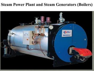
  • 1. Steam Power Plant and Steam Generators (Boilers)
  • 2. Steam Power Plant • Steam power plants are producing about half of the total power requirement in India. • In a steam Power plant, thermal energy is used to raise steam, that is used to run steam turbines to produce mechanical energy. • This mechanical energy is converted into electrical energy in a generator. • Steam power plants are suitable for large scale production of electrical power.
  • 3. Selection of Site for Steam Power Plant • The factors to be considered while selecting a site for a steam power plant are as follows- 1) Availability of fuel 2) Transportation 3) Availability of water 4) Ash Disposal 5) Nature of land 6) Space Area
  • 4. 1)Availability of fuel: The site selected should have abundant sources of fuel (generally coal, petroleum or natural gas). A steam power plant using Coal as fuel needs about 1,500 tones of coal for every 100 MW of power produced.
  • 5. 2) Transportation: Though having a plant at the fuel source does not require transportation for fuel, it may be away from the place of use. This leads to high transmission costs and loss of power, hence possible to locate a site for economical power transmission and fuel transmission. Rope-ways or railway are the better choices of transportation at the interior places. Sea transportation is economical for plants and fuel source near sea shores.
  • 6. 3) Availability of water: A steam power plant requires high volumes of water for use as feed water, ash handling and mainly for condensing. About 50 to 60 thousand tones of water per hour is required for every 100 MW of power developed, as cooling water and makeup water for the feed. A good quality of drinking water is also essential for the use of employees.
  • 7. 4) Ash Disposal: • Generally the steam power plants produce ash about 20 to 30% of fuel burnt. • The ash to be disposed may be several thousand tones a day. • Hence the site selected should have provision for proper disposal of ash.
  • 8. 5) Nature of land: • The soil of the site selected should have a good bearing capacity as it has to support huge structures and dynamic forces in operating conditions. • A bearing capacity of 10 kgf/cm2 is essential to set up a steam power plant.
  • 9. 6) Space Area: Steam power plants need the maximum space area all other power plants. They require larger space areas for coal yards, buildings, machinery & equipment, cooling towers, ash disposal and for residential purpose. About 500 acres of land is necessary for every 100 MW of power produced.
  • 10. Layout of a Steam Power Plant Essential components and systems of a steam power plant- 1) Turbine Generator 2) Furnace Boiler 3) Fuel Handling System 4) Ash Handling System 5) Draught System 6) Condensing System 7) Water Cooling System 8) Lubrication System
  • 11.
  • 12. 1) Turbine Generator • This is the central power system where electrical energy is generated. In the turbine velocity and pressure energy of the steam is converted into kinetic energy, turbines are directly coupled to the generators which develop electrical energy. • The steam turbines used may be either impulse or reaction turbines based on the requirements of power generation. • The turbines are equipped with governing systems to control the power output of the plants.
  • 13. 2) Furnace-Boiler • This is the unit of the plant where steam is generated by burning fuels. • The type of fuel used may be solid, liquid, gaseous or pulverized based on the availability of fuel and design of furnace. • A combination of fuels is also possible. • Water used to raise steam must be free from any suspended or dissolved impurities. • The impure water may lead to scale formation and corrosion of the boiler plate or may cause foaming which all hamper the boiler operation. The type of boiler used depends upon the pressure and quantity of steam required.
  • 14. 3) Fuel handling system • Steam power plants generally use coal or pulverized coal as the fuel. • The fuel is required in large quantities, which necessitates a fuel handling system. • Usually, belt conveyors or bucket elevator are used for handling the fuel.
  • 15. 4) Ash handling System • The ash produced in a steam power plant amounts to about 10-20 percent of the fuel burnt. • This should be removed from the furnace and disposed. • This is done by a proper ash handling system. The system used may be either mechanical, hydraulic, pneumatic or steam jet type. • This selection is based on the quantity of ash to be handled and the type of boiler used.
  • 16. 5) Draught System • This system is essential to supply required quantity of air for combustion of the fuel, to force the flue gases through the furnace boiler system and finally to discharge the gases to the atmosphere through a chimney. • The draught system may be either natural or mechanical type.
  • 17. 6) Condensing System • The used steam is pure having a higher temperature which can be condensed and fed to the boiler. • This increases the efficiency of the plant. Generally water to steam type of condensers are used with necessary pumping arrangements.
  • 18. 7) Water Cooling System • The quantity of water used in condensing the steam is very high and should be reused in the condenser. • This water gets heated up after condensing the steam and this water is to be cooled for recirculation. • This is achieved by cooling towers, where water is pumped to a high altitude and allowed to flow over baffles. • During this the water gets cooled which is pumped back to the condensing unit.
  • 19. 8) Lubrication System • The turbines and generators are run at high speeds (3000 rpm). • A proper lubrication system is essential to keep the system running continuously. • The lubrication system not only avoids wear and tear but also provides a little cooling effect for the bearings of the system.
  • 20. 8) Other Accessories. • In addition to the above systems a steam power plant, is also equipped with accessories like economiser, super heater, de super heater, air pre heater, soot blowers and furnace cleaning units.
  • 21. FUELS FOR STEAM GENARATION • Steam power plant uses fossil fuels to generate steam. • The fuel may be in different form such as solid, liquid, pulverized or gaseous. • The selection of the type of fuel depends on the availability of fuels and economical conditions.
  • 22. Types of Fuels • The important fuels are as follows- 1) Solid fuels 2) Liquid fuels 3) Gaseous fuels
  • 23. 1) Solid fuels • Coal is the major fuel used for thermal power plants to generate steam. • Coal occurs in nature, which was formed by the decay of vegetable matters buried under the earth millions of years ago under pressure and heat. • This phenomenon of transformation of vegetable matter into coal under earths crust is known as Metamorphism. • The type of coal available under the earths surface depends upon the period of metamorphism and the type of vegetable matter buried, also the pressure and temperature conditions.
  • 24. • The major constituents in coal moisture (5- 40%),volatile matter (combustible & or incombustible substances about 50%) and ash (20-50%). • The chemical substances in the coal are carbon, hydrogen, nitrogen, oxygen and sulphur. • In the metamorphism phenomenon, the vegetable matters undergo the transformation from peat to anthracite coal, with intermediate forms of lignite and bituminous coal.
  • 25. 2) Liquid Fuels • All types of liquid fuels used are derived from crude petroleum and its by-products. • The petroleum or crude oil consists of 80-85% C, 10- 15% hydrogen, and varying percentages of sulphur, nitrogen, oxygen and compounds of vanadium. • The crude oil is refined by fractional distillation process to obtain fuel oils, for industrial as well as for domestic purposes. • The fractions from light oil to heavy oil are naphtha, gasoline, kerosene, diesel and finally heavy fuel oil. • The heavy fuel oil is used for generation of steam.
  • 26. The use of liquid fuels in thermal power plants has many advantages over the use of solid fuels. Some important advantages are as follows: 1) The storage and handling of liquid fuels is much easier than solid and gaseous fuels. 2) Excess air required for the complete combustion of liquid fuels is less, as compared to the solid fuels. 3) Fire control is easy and hence changes in load can be met easily and quickly. 4) There are no requirements of ash handling and disposal. 5) The system is very clean, and hence the labour required is relatively less compared to the operation with solid fuels.
  • 27. 3) Gaseous Fuels • For the generation of steam in gas fired thermal plants, either natural gas or manufactured gaseous fuels are used. • However, manufactured gases are costlier than the natural gas. • Generally, natural gas is used for power plants as it is available in abundance. • The natural gas is generally obtained from gas wells and petroleum wells.
  • 28. • The major constituent in natural gas is methane, about 60-65%, and also contains small amounts of other hydrocarbons such as ethane, naphthene and aromatics, carbon dioxide and nitrogen. • The natural gas is transported from the source to the place of use through pipes, for distances to several hundred kilometers. • The natural gas is colourless, odourless and non-toxic. • Its calorific value ranges from 25,000 to 50,000 kJ/m3, in accordance with the percentage of methane in the gas.
  • 29. • The artificial gases are producer gas, water gas coke-oven gas; and the Blast furnace gas. • Generally, power plants fired with artificial gases are not found. • The gaseous fuels have advantages similar to those of liquid fuels, except for the storage problems. • The major disadvantage of power plant using natural gas is that it should be setup near the source, otherwise the transportation losses are too high.
  • 30. Fuel Feeding & Firing Systems • In India, steam power plants use coal as the fuel, since coal is the major source and also it is available in abundance. • Power plants with smaller outputs are using liquid fuels like diesel oil and heavy fuel oils. • All major steam power plants are run by burning coal. • Coal is generally referred to as fuel, which is used either in solid or powdered form. • The coal in powdered form is termed the pulverized coal.
  • 31. • The economical working of a steam power plant depends upon the efficient combustion of fuel. Hence fuel feeding and firing system to the furnace plays an important role. • The different firing methods are: 1. For solid fuel • a) Hand firing • b) Mechanical stoker firing 2. For pulverised fuel • a) Unit system, • b) Bin or central system
  • 32. Hand Firing : Though hand firing is simple and cheaper it is not generally used, because of the following reasons: 1) It has low combustion efficiency. 2) Slow response to the load fluctuations. 3) Combustion control is difficult. 4) Suitable only for small power plants.
  • 33. Mechanical Stoker Firing : Even though it is costlier, generally they are used to feed the solid fuels in small and medium size power plants, because of the following reasons: • 1) Combustion is more efficient. • 2) Fuel handling is automatic and combustion control is easier. • 3) Faster response to load fluctuations. • 4) Low quality fuels can be successfully burnt. • 5) Suitable for small to high capacity plants.
  • 34. Principle of Stokers The different types of stokers work on the following principles. a) Principle of overfeed stokers b) Principle of under feed stoker
  • 35. a) Principle of overfeed stokers • A fully built up overfeed stoker will have the beds of green coal (raw coal), incandescent coke and ash over the grate. • In this the primary air enters the grate from the bottom, which cools the grate while moving up and gets heated as it passes through hot ash bed.
  • 36.
  • 37. • The hot air then passes through the bed of incandescent coke, where oxygen reacts with the carbon in the coke to form carbon dioxide, carbon monoxide and hydrogen. • Part of carbon dioxide formed reacts with carbon in the fuel to form carbon monoxide. • The gases leaving the bed of incandescent coke consist of nitrogen, carbon dioxide, carbon monoxide, hydrogen and water.
  • 38.
  • 39. • To these gases, then an additional air termed the secondary air is supplied from the sides to burn the combustible gases like the carbon monoxide, hydrogen and other volatile matters. • The burnt hot gases entering the boiler consist of carbon dioxide, nitrogen, oxygen, and water. • It may also contain carbon monoxide, if the combustion is incomplete. • The primary and secondary air to the stoker are supplied under pressure with the help of blowers.
  • 40. b) Principle of under feed stoker • In this the coal is charged from the bottom, and the primary air under pressure also moves from the bottom through the holes in the grate. • This stoker has the layers of ash, incandescent coke bed and raw coal, in the reverse direction as compared to that of the overfeed stoker. • In operation the primary air entering from the bottom through the grate holes comes in contact with the coal and then passes through the bed of incandescent coke.
  • 41.
  • 42. • In operation the primary air entering from the bottom through the grate holes comes in contact with the green coal and then passes through the bed of incandescent coke. • Initially, air reacts with carbon in the coke to form carbon dioxide, and the moisture in the air reacts to release carbon dioxide, carbon monoxide and hydrogen. • While these gases pass over the ash bed, secondary air is supplied for their complete combustion. • This method is most suitable for semi-bituminous and bituminous coals which have high volatile-matter.
  • 43. Types of Stokers • Different types of stokers are 1. Over feed stokers • a) conveyer stoker • i) Chain grate stoker • ii) Traveling grate stoker • b) Spreader stoker 2. Under feed stokers • a) single retort stoker • b) Multi-retort stoker
  • 44. 1) Chain & traveling grate stokers • The chain grate and traveling grate stoker are similar in operation, but differ only in grate construction. `
  • 45. Chain Grate or Traveling Grate Stoker Boiler  Coal is fed on one end of a moving steel chain grate  Coal burns and ash drops off at end  Coal grate controls rate of coal feed into furnace by controlling the thickness of the fuel bed.  Coal must be uniform in size as large lumps will not burn out completely  Bed thickness decreases from coal feed end to rear end and so more air at front and less air at rear end to be supplied  Water tube boiler
  • 46. • A chain grate stoker consists of an endless chain which forms the support for the fuel bed. • The chain is made of cast iron links connected by pins. • The chain is held over two sprockets as shown figure, and travels from one end of the furnace to the other end. • The sprocket at the front end is driven by an electric motor.
  • 47. • The coal is fed at the front end through a hopper which is carried by the chain to the other end, hence into the furnace. • The air necessary for the combustion of the fuel is supplied through the air inlets below the traveling grate. • The secondary air is supplied through the openings in the top roof as shown in figure.
  • 48. • The rate of fuel supplied to the grate and hence the heat to the boiler can be controlled by two means. • The first means is to control the depth of the coal bed on the grate by controlling the feed to the hopper. In the second method, the speed of the chain grate can be adjusted to meet the boiler operation requirements. • The chain grate stokers are widely used for burning non-caking (that does not form a solid mass while burning), free burning, volatile and high ash content coals.
  • 49. Advantages of chain grate stokers 1) It is simple in construction and operation. 2) Its initial and maintenance costs very low. 3) It doesn't have ash cleaning problems. 4) Combustion control is simple, by control of feed or chain speed, along with the air supply. 5) Its combustion efficiency is high.
  • 50. Disadvantages 1) It is suitable only for small capacity plants. 2) Coal losses are high as the un burnt coal may also move with ash. 3) If caking coal is used ash clinker problems may rise. • In the traveling grate stoker, the chain grate is replaced by grate bars that support the burning fuel. • Also the grate is inclined towards the inlet of the furnace. • The fuel movement is accomplished and controlled by vibration of the grate. • The air supply similar to the chain grate stoker.
  • 51. 2) Spreader or Sprinkler Stoker • In this type stoker, coal from the hopper is fed on to a rotating feeder which in turn feeds the, to a spreader or sprinkler, and feed according to the requirements. • Feeder is a rotating drum fitted with blades on its periphery. • Other type of feeders such as reciprocations, endless belts or spiral worms can also be used.
  • 52.
  • 53. • The feeder continuously supply the coal on to the spreader, a fast moving drum with blades, which in turn distributes and feeds the coal on to the grate as shown in figure. • The fuel feed rate and the supplied to the boiler can be controlled by controlling the feed to the hopper or by controlling the spreader speed.
  • 54. • Fig. shows the schematic arrangement of a spreader stoker. • In this type stoker, coal from the hopper is fed on to a rotating feeder which in turn feeds the, to a spreader or sprinkler, and feed according to the requirements. • Feeder is a rotating drum fitted with blades on its periphery. Other type of feeders such as reciprocating rams, endless belts or spiral worms can also be used.
  • 55. • The feeder continuously supplies the coal on to the spreader, a fast moving drum with blades, which in turn distributes and feeds the coal on to the grate as shown in figure. • The fuel feed rate and the supplied to the boiler can be controlled by controlling the feed to the hopper ar by controlling the spreader speed.
  • 56. Advantages of spreader stoker 1) Its operation is simple and economical. 2) A wide variety of low quality coals can be burnt successfully. 3) Preheated air can be used for improving the efficiency of operation. 4) The fuel burns rapidly and hence the caking tendency is very low, even with the use of caking coals. 5) It can responds quickly to load variations;
  • 57. Disadvantages 1) It is not possible to burn varying sizes of coal and only crushed, sized coal can be used. 2) A part of the charge is burnt in suspension and hence fly ash is discharged with flue gases. This necessitates an suitable dust (or fly ash) collector system. 3) Un burnt carbon particles may escape through the flues and reduce the combustion efficiency.
  • 58. 3) Single Retort Stoker • The principle of construction of a single retort stoker is illustrated in Fig. • In this stoker, fuel is burnt on a retort. • The fuel is fed through a hopper and pushed on to the retort by a piston ram movement.
  • 59.
  • 60. • With the feeding from the bottom, gradually the burning coat rises up. • Above the green coal an incandescent coke layer is formed, and above which the ash layer is formed. • With the continuous feeding of green coal, the ash level rises that is removed by ash raker.
  • 61. 4) Multi Retort Stoker • It contains of a series of retorts (5 to 20) with tuyers and pushers. • It also consists of a fuel hopper and a coal pusher at the hopper end as shown in figure. • The coal fed through the hopper is pushed by the main pusher driven by a ram. The distributing pushers in the retorts push the coal and distribute it to all the retorts. • The movement of the fuel bed by the pushers helps in minimizing the clinker formation.
  • 62.
  • 63. • The primary air enters the wind box below the retorts, and flows through the retorts. • An air damper is provided at the air inlet in the wind box to control the airflow to the furnace. • The airflow to the extension grate at its entry is further controlled by another damper, since the extension grate requires small quantity of air with less fuel burning on it. • The ash formed from all the retorts falls into the ash pit.
  • 64. Advantages of multi retort stoker 1) Since the combustion rate is high, such a stoker is most suitable for high capacity power plants. 2) The combustion efficiency of this stoker is very high. 3) As the fuel is pushed off by the pushers, they perform the cleaning action as well. 4) Automatic combustion control can be adopted in this stoker. 5) This stoker can respond quickly to variations in demand.
  • 65. Disadvantages • 1) The operation and maintenance is expensive. • 2) The initial investment is high. • 3) Ash clinker problems may arise. • 4) It needs a larger area for installation and operation. • 5) Low grade, high ash fuels cannot be burnt successfully.
  • 66. Pulverized Coal Firing • In pulverised fuel firing system, the coal is powdered and then charged into the combustion chamber with the help of hot air current. • The main purpose of pulverizing coal is to increase the surface area of exposure to the combustion process, which results in faster and efficient combustion.
  • 67. • In burning the pulverized coal, the secondary air required for the complete combustion of fuel is supplied separately to the combustion chamber. The resulting turbulence in the combustion chamber helps for uniform mixing of fuel and air. • The air required to carry the pulverized coal and dry it before entering the combustion chamber is termed the Priming Air, and the air supplied separately for complete combustion is termed the Secondary Air.
  • 68. • Pulverized coal firing systems are universally adopted far large scale power plants. • The choice of pulverized fuel firing system depends upon the size of the boiler unit, type of coal available, cost of coal, type of load (i.e., fluctuating or constant), the load factor and availability of trained personnel. • Generally such systems are not economical for small capacity thermal power plants.
  • 69. Advantages of using pulverised coal 1) A wide variety of low grade fuels (coal) can be used and burnt easily. 2) Greater surface area is exposed for combustion and hence combustion is faster and efficient. 3) The system is free from clinker and slagging troubles. 4) Combustion control is easy, and hence the system gives fast response to load changes.
  • 70. 5) Preheated secondary air (up to 350°C) can be used, resulting in rapid flame propagation and faster heat supply to the boiler. 6) The pulverizing system can be maintained or repaired without affecting the combustion process. 7) It has a very high rate of heat release. 8) Banking losses (un burnt fuel with ash) are lower, as compared to stoker firing. 9) The boilers can be started from cold very rapidly. 10) Usually combustion will be smokeless.
  • 71. Disadvantages of Pulverised system 1) The capital investment of the system is high as it requires additional equipments (for pulverizing, and handling). 2) Its operation and maintenance costs are very high. 3) It produces fly-ash/fine dust and needs costly fly- ash removal equipments like electrostatic precipitators. 4) The chances of explosion are high as coal burns like a gas.
  • 72. 5) The storage of powdered coal requires special attention as it has possibilities of fire hazards. 6) Skilled workers are required for safe-operation and maintenance. 7) Air pollution takes place by the emission of fine particles of grit and dirt. 8) The removal of liquid slag formed from low fusion temperature ash requires special handling equipments.
  • 73. Pulverised Fuel Burning System • There are two common methods of pulverized fuel burning systems- 1. Unit system 2. Central or Bin system
  • 74. a) Unit System • In this system, each burner and a pulveriser constitute a unit. • It consists of a raw coal bunker, a feeder, pulverizing mill, separator, and the burner. • In operation, the raw coal is supplied to the bunker, where it is crushed to the required sizes.
  • 75.
  • 76. • The crushed coal is then fed to the pulverizing mill through the feeder at the required rate, depending upon the combustion requirements. • Hot gases are passed through the feeder to dry the coal. • The dried coal is pulverised in the mill and it is carried to the burner. • An induced draft fan is used at the pulverizer to carry the powdered coal to the burner. • A separator is provided to separate the grains of bigger size from the powder and returned to the pulveriser for further crushing.
  • 77. Advantages 1) It is simple in operation and economical than the central system. 2) Combustion is controlled directly after pulveriser. 3) Maintenance cost is low. 4) Fuel supply to the burner can be controlled easily.
  • 78. Disadvantages 1) The performance of the pulverizing mill is poor as the system operates at variable loads. 2) The total capacity of mills must be higher than the central system. 3) The unit system of fuel burning is less flexible. 4) Whenever any of the auxiliaries fails the burner has to be put-off. 5) Wear and tear of the fan blades is more since it handles hot air and coal particles. 6) Strict maintenance of pulverizing mill is a must for perfect operation of the system.
  • 79. b) Central or Bin System • Fig. shows schematic arrangement and the principle of operation of a central, or bin system for burning pulverised coal. • The crushed raw coal is dried using hot air or flue gases and fed to the pulveriser. • The pulverised coal from the pulverizing mill is passed to the cyclone separator where over- sized particles are separated and fed back to the mill.
  • 80.
  • 81. • The pulverised coal is then transferred from the separator to the central bunker (bin) through a conveyer system. • The pressurized air from the forced draft fan, supplies the stored coal to the burner. • This air not only carries the fuel, but also acts as the primary air for the combustion of the fuel. • Secondary air is supplied to the burner separately to assist in the complete combustion.
  • 82. Advantages 1) It is simple in operation and economical than the central system. 2) Combustion is controlled directly after pulveriser. 3) Maintenance cost is low. 4) Fuel supply to the burner can be controlled easily.
  • 83. Disadvantages 1) The performance of the pulverizing mill is poor as the system operates at variable loads. 2) The total capacity of mills must be higher than the central system. 3) The unit system of fuel burning is less flexible. 4) Whenever any of the auxiliaries fails the burner has to be put-off. 5) Wear and tear of the fan blades is more since it handles hot air and coal particles. 6) Strict maintenance of pulverizing mill is a must for perfect operation of the system.
  • 84. Advantages of Central system 1) Central system is highly flexible and hence can meet any quick changes in the demand. 2) Burner operation is independent of coal pulverization. 3) The pulverizing mill can be stopped when there is a good stock of pulverised fuel in the bin. 4) The fan wear is less as it handles only natural air. 5) Coal size can be controlled efficiently.
  • 85. Disadvantages 1) Central system is expensive, and occupies more space. 2) It requires complicated coal handling systems. 3) Power consumption in auxiliaries is high. 4) Chances of fire hazards are more since the pulverised fuel is stored. 5) Operation and maintenance costs are high.
  • 86. Pulverised Coal Burners • Burners are devices that allow uniform mixing of fuel with air hence lead to efficient and complete combustion. • The burner receives the fuel along with the primary air in a central passage, while the secondary air is supplied around the passage. • A good design of the burner is essential to achieve complete combustion of the fuel. Thus a good burner should meet a number of design requirements.
  • 87. The important requirements of an efficient pulverised coal burner are as follows: 1) It should mix the fuel and primary air thoroughly and inject the mixture into the furnace. 2) It should create proper· turbulence for air-fuel mixing and maintain a stable combustion. 3) It should be able to control the flame shape and flame travel by varying the amount of secondary air. 4) Coal-air mixture should move away from the burner at a rate equal to the flame travel so as to avoid flash back. 5) It should be projected properly to avoid over heating, wear and internal fires.
  • 88. TYPES OF BURNERS • There are four types of burners used for the pulverised fuel burning. • The principles of operation of these burners are briefly discussed. 1) long-Flame or U-Flame or Stream lined burner 2) Short Flame or Turbulent Burner 3) Tangential Burners 4) Cyclone Burner
  • 89. 1) long-Flame or U - Flame or Stream lined burner • The arrangement of a long flame, U-shaped burner is schematically shown Fig. • The burner is placed such that it produces a long, u-shaped flame. Pulverized
  • 90. • The burner injects a mixture of primary air and fuel vertically downwards in thin streams practically with no turbulence and produces a long flame. • Secondary hot air is supplied at right angles to the flame which provides necessary turbulence and mixing for proper and rapid combustion. • A tertiary air is supplied around the burner for better mixing of the fuel with air. • In this burner due to long flame travel, high volatile coals can be burnt easily. • Velocity of the air-fuel mixture at the burner tip is around of 25 m/sec.
  • 91. 2) Short Flame or Turbulent Burner • The schematic arrangement of a short-flame or turbulent burner is illustrated in fig. • Pulverized
  • 92. • These burners are generally built into the furnace walls, so that the flame is projected horizontally into the furnace. • Primary air and the fuel mixture is combined with secondary air at the burner periphery, before the entry into the furnace as shown in figure.
  • 93. • This burner gives out a turbulent mixture which burns rapidly and combustion is completed within a short distance. • Therefore, the combustion rate is high. • The velocity of mixture at the burner tip is about 50 m/sec. • In such burners, the bituminous coal can be burnt easily. • Modern high capacity power plants use such burners.
  • 94. 3) Tangential Burners • These burners are built into the furnace walls at the corners. • They inject the air-fuel mixture tangentially to an imaginary circle in the centre of furnace. • As the flames intercept, it leads to a swirling action. • This produces sufficient turbulence in the furnace for complete combustion. • Hence in such burners, there is no need to produce high turbulence within the burners. Tangential burners give fast and high heat release rates.
  • 95.
  • 96. Pulverized Fuel Boiler Tangential firing Coal is pulverised to a fine powder, so that less than 2% is +300 microns, and 70-75% is below 75 microns. Coal is blown with part of the combustion air into the boiler plant through a series of burner nozzles. • Combustion takes place at temperatures from 1300-1700°C • One of the most popular system for firing pulverized coal is the tangential firing using four burners corner to corner to create a fire ball at the center of the furnace.
  • 97. • Theses burners can also be constructed so as to move up and down through some angle, ±30 degrees. With this arrangement, the position of the turbulent mixture and the point of combustion can be raised or lowered, and hence the furnace temperature can be easily controlled. • In these burners, fly ash produced in the combustion process may get deposited on the exposed furnace wall surfaces and solidify as slag. This in turn will affect the heat transfer capability of the boiler.
  • 98. • This can be avoided by providing sufficient heat absorbing surface to cool the molten ash below its softening temperature by radiation, before it reaches the furnace wall surfaces. • This problem does not exist in modern boilers, since the furnace walls are water-cooled type.
  • 99. 4) Cyclone Burner • This burner burns the coal particles in suspension, thus avoiding fly-ash problems, which is common in other types of burners. • This burner uses crushed coal (about 5 to 6 mm size) instead of pulverised coal. • This burner can easily burn low grade coal with high ash and moisture content. • Also, this can burn biofuels such as rice husk. • The principle of operation of a cyclone burner is illustrated in Fig.
  • 100.
  • 101. • The cyclone burner consists of a horizontal cylinder of about 3 m diameter and about 4 m length. • The cylinder wall is water cooled, while the inside surface is lined ,with chrome ore. • The horizontal axis of the burner is slightly inclined towards the boiler. • The coal used in cyclone burner is crushed to about 6 mm size.
  • 102. • Coal and primary air (about 25% of the combustion or secondary air) are admitted tangentially into the cylinder so as to produce a strong centrifugal motion and turbulence to the coal particles. • The primary air and fuel mixture flows centrifugally along the cylinder walls towards the furnace. • From the top of the burner, the secondary air is also admitted tangentially, at a high velocity (about 100 m/s). • The high velocity secondary air causes further increase in the centrifugal motion, leading to a highly turbulent whirling motion of the coal air mixture.
  • 103. • Tertiary air (about 5 to 10% of the secondary air) is admitted , axially at the centre as shown in fig, so as to move the turbulent coal-air mixture towards the furnace. • The coal is burnt completely within the burner and only hot gases enter the furnace. • Such burners produce high heat and temperatures (about 1000°C). • Due to high temperature burning, the ash melts in the form of slag, and is drained out periodically at the bottom.
  • 104. Advantages of cyclone burner 1) Since it uses crushed coal, it saves the cost of pulverization. 2) All the incombustible are retained in cyclone burner, and hence the boiler fouling problems are reduced. 3) It requires less excess air, as it uses forced draught. 4) Slag-recovery is around 80% and dust passing to the stack is about 10%. Thus simple equipment can be used for dust removal. 5) Fly ash problem is reduced to a great extent. 6) Low grade fuels can be used.
  • 105. Disadvantages I) It requires high pressure draught and consumes higher power. 2) It produces more oxides of nitrogen, which creates atmospheric pollution.
  • 106. Pulverizing Mills • The coal is pulverised by abrasion, crushing or impact (hammer) action. • The different types of pulverizing mills used are as follows: 1. Ball Mill 2. Ball and Race Mill 3. Bowl Mill 4. Hammer Mill
  • 107. 1. Ball Mill • It consists of a large steel drum, a hopper, classifier and exhauster. • The steel drum is the pulversier, which is partly filled with steel balls of different sizes. • The diameter of the balls varies from 25 to 50 mm. • The drum is driven by a drive mechanism, and rotates at a speed of about 120 m/min (peripheral velocity). • In operation, sized raw coal (about 60 mm) is fed to the hopper. • Coal passes through the classifiers and enters the steel drum through the screw conveyors on either sides as shown in figure.
  • 108.
  • 109.
  • 110.
  • 111. • As the drum is continuously rotating, the coal is impacted between balls, gets crushed and pulverised. • Hot air, heated from the-flues is passed into the drum. • Hot air carries the powdered coal and passes through the classifier. • In the classifier the over sized coal particles are separated and sent back to the drum along with the raw coal for further powdering. • Two induced draft fans pick up the pulverised coal from the classifier, and sent to the burners. • A typical ball mill to pulverize 10 tones of coal requires about 30 tones of steel balls, and consumes about 25 kW of power per tone of coal pulverised.
  • 112. 2. Ball & Race Mill • This mill is also termed the contact mill, since the pulverizing action takes place between two races that are in contact with rolling balls.
  • 113.
  • 114. • It consists of an upper stationary race, and 10 moving race and balls in between the races as shown in figure. • The lower race driven by bevel gears. • The coal is fed through the side hopper mounted at the top of the mill. • In operation, the fed coal from the hopper enters the race gaps through circumference periphery. • The coal comes between the balls and the races and crushed.
  • 115. • There also exists abrasion action between the ball/race and the coal. • coal in between the races and the balls is continuously crushed in this fashion pulverised. • The races are forced together under the action of springs, so as to a the crushing force on the coal. • Also, the spring pressure can be varied to suit pulverizing size needs. • Hot air is supplied to the mill through the annular space surrounding the race by a forced draught fan. • The hot primary air picks up the pulverized coal, rises up the mill and passes through the classifier.
  • 116. • In the classifier, the large sized coal particle are thrown out by centrifugal action, while the fine powder moves along with the air. • From the classifier, fully powdered coal is supplied to the burners. • A typical ball and race mill consumes about 15 kW of power per tone of the coal pulverised. • Compared to ball mills, such mills are simple in construction, easy economical for operation. • Also ball and race mills require lesser floor area consume less power.
  • 117. Bowl Mill • It consists of a moving bowl driven by an electric motor. • The stationary rollers are located on the bowl wall. • The rollers are spring loaded to adjust the pulverizing pressure. • The coal fed from the hopper is ground in between the rollers and the rotating bowl. • Hot air enters the bowl from the bottom and carries with it the powdered coal particles. • The large sized particles are separated in the classifier and fall back into the bowl. • The pulverised coal from the mill is sucked by an induced draft fan and is supplied to the burners, as shown in figure.
  • 118.
  • 119.
  • 120.
  • 121. Fuel Oil Burning Systems • Burners are used for burning fuel oil. • Basically, a burner is designed to atomize or vaporize the oil, mix it with suitable amount of air and allow for the efficient combustion. • The different types of oil burners are: 1. Vaporizing burners a) Atmospheric pressure burner b) Recirculation burner c) Wick type burner 2. Atomizing burners a) Rotary cup-type b) Mechanical or oil pressure burner c) Steam or high pressure air burner
  • 122. • Vaporizing burners are widely used in domestic and industrial applications. • In such burners the fuel is vaporized by heating. • In atomizing burners the fuel oil is atomized, that is split into fine particles so as to increase the area of exposure to the air. • For this purpose, centrifugal force, or oil under high pressure, or the high pressure air or steam are commonly used.
  • 123. 1) Rotary cup burner • The construction of a common rotary cup oil burner is schematically illustrated in Fig.
  • 124. • It consists of a horizontal rotary cup that runs at a high speed (about 3000 rpm). • The oil is supplied at the center though the inlet port, and it is sprayed on the inner surface of the rim of the high speed rotary cup. • The oil is spun off the high speed cup due to centrifugal force as very fine particles into the air stream entering the cup periphery, thus atomizing the oil.
  • 125. • The direction of rotation of the cup and the direction of flow of air are opposite such that both mix thoroughly by swirling action as they leave the burner, and burn easily. • Such burners have a wide capacity ranges, as the rate of oil burnt can be easily regulated by controlling the inlet port size at the centre of the cup.
  • 126. 2) Mechanical or oil pressure burner • The construction of a typical oil pressure burner is schematically illustrated in Fig. • In these burners the oil is subjected to high pressure and atomized by passing it through an orifice.
  • 127. • The oil is supplied under high pressure of 10 to 20 bar. • Usually the oil passes through a swirl chamber and thoroughly get mixed with primary air. • As the oil under pressure is ejected out of the orifice, it breaks down into fine particles, forms a conical oil mist and easily undergoes combustion. The oil flow through the orifice can be regulated with the help of control piston (plunger), which closes the tangential slots to the required level.
  • 128. 3) Steam or high pressure air burner • In these burners the oil is atomized with the help of high pressure compressed air or steam. • The high pressure air or steam enters the nozzle and mixes with the fuel. • The air and oil ,are supplied through two different channels, and are mixed either within the nozzle before leaving it or outside the nozzle after leaving it. • The principle of such burners is schematically shown in Fig:
  • 129. The principle of such burners is schematically shown in Fig:
  • 130. Coal Handling • Coal handling refers to the process of conveying the coal from the point of unloading to the place of use. • It is carried out by several means depending upon the requirements of the power plant. • The important equipment used for transporting the coal are in a power plant are as follows: • 1) Belt conveyors • 2) Screw conveyors • 3) Bucket elevators • 4) Grab Bucket elevators
  • 131. 1) Belt Conveyor • It is basically an endless moving belt over which the coal is moved, The belt is connected to a pair of drums at the ends, and supported at the upper portion by a series of rollers (idlers) at regular intervals, as illustrated in Fig. • The belt is usually made of strong and flexible materials such as rubber or canvas. • Belt conveyors are useful for transportation of large quantity of coal over long distances in power plants.
  • 132. • The belt is inclined at about 15-20 degrees from the charge end to the discharge end. • The average speed of belt conveyors is in the range of 50 to 100 m/minute.
  • 133. Advantages 1) It is simple in construction and operation. 2) The operation is smooth and clean. 3) It requires less power compared to other systems. 4) Large quantities of coal can be conveyed quickly and continuously. 5) It is comparatively cheaper in maintenance and operation.
  • 134. 2) Screw Conveyors • It consists of an endless helical screw around a shaft. • It is supported on two bearings and one side of, the shaft is coupled with a driving motor. • The screw is covered with a cylindrical trough, Coal is transported along the helical screw as it rotates in the trough. • The diameter of the screw is about 200mm and it runs at about 100 rpm. • A screw conveyor is most suitable for medium scale coal transportation (about 100 to 125 tones/ hour).
  • 135.
  • 136.
  • 137. Advantages 1) It is relatively inexpensive. 2) It requires minimum space for operation. 3) It is very simple and compact. 4) It can be made dust - tight.
  • 138. Disadvantages 1) Power consumption is comparatively high. 2) It is suitable for only short distance transportation (around 20 to 30 m). 3) Wear and tear of the parts is more.
  • 139. 3) Bucket Elevators • This type of conveyer is used for moving the coal vertically up. • It consists of a number of buckets fixed on to a chain moving over two sprockets, as shown in Fig. • In this, coil is picked up by the up-moving buckets from the bottom part of the conveyer. The coal form the buckets id discharged at the top due to centrifugal force as the buckets change the direction. • Usually such conveyors can transport coal to height of up to 30 m.
  • 140.
  • 141.
  • 142. 4) Grab Bucket Elevator • The construction of a grab bucket elevator illustrated in Fig. • It consists of a crane which can lift the coal and move Circumferentially in a given location. • This system is most suitable for handling coal at the coal store yard. • Thus used to load coal from the yard to the wagon tippler, which then moves inside the plant.
  • 143.
  • 144.
  • 145. • This elevator has the unique advantage of operating as a crane as well as moving in all directions. • This helps in lifting the coal using the, grab bucket from the yard, change its direction, move to the required distance and unload it onto the wagon tippler. • The grab bucket with bottom closed condition picks up the coal from the heap and when moved to the wagon opens its split opening bottom, thereby dumping the coal onto the wagon.
  • 146. Flow of Coal in Power Plants • The flow of coal in a power plant takes place in the following sequences: 1) Storage yard to wagon tippler using grab bucket elevator. 2) Wagon tippler to belt conveyor: 3) Belt conveyor to crusher, and then to separator. 4) Separator to belt conveyor to bucket elevator. 5) Bucket elevator, to pulveriser. 6) Pulveriser to bin to furnace.
  • 147. Line diagram of the coal flow sequences.
  • 148. Line diagram of the coal flow sequences. 1) The raw coal from the storage yard is lifted and loaded to the wagon tippler using a grab bucket elevator. Grab bucket elevator is conveniently load coal as it operates like a crane and moves as well in all directions. 2.) The wagon tippler moves on rails from the storage yard to the belt conveyor and the coal is unloaded by tilting the wagon tippler by a tilting mechanism.
  • 149. 3) The belt conveyor carries the raw coal to a size crusher where the coal is crushed to 50 mm size and passes to a vibration separator. Oversized pieces from the separator are lifted and transported back to the crusher using a bucket elevator. 4) The sized coal then moves on to another belt conveyor and lifted up by another bucket elevator (if necessary) to the hopper of the pulverizing mill.
  • 150. 5) The coal is then powdered in the pulverizing mill, where hot air is passed to remove the moisture from the coal and for easy powdering action. The powdered coal is sucked by an induced draft fan and passed through the cyclone separator, and the fuel is stored in a bin. Over sized coal from the cyclone separator falls back to the pulverizing mill. 6) The fuel from the storage bin is then fed through the pulverised fuel feeder by a forced draft fan to the burner mounted in the furnace walls.
  • 151. Ash Handling • Coal based steam power plants produce a large quantity of ash. • The amount of ash produced is about 20 to 30% of the coal burnt. • Ash handling in power plants is a major problem since the ash taken out from the furnace is hot, dusty, massive to handle and comes out with some gases that are hazardous to hearth.
  • 152. • Generally, before handling the ash from the furnace is first quenched in water for the following reason 1) Water quenching reduces the temperature of ash, hence can be handled easily. 2) It dilutes the ash, thus reducing its corrosive characteristics. 3) Large lumps of ash clinkers get disintegrated after quenching, thus making easier to handle. 4) On quenching, the dust particles and some hazardous gases in the ash get dissolve in water, and reduce the pollution problems.
  • 153. Requirements of Ash Handling Equipments 1) Capital investment; operating and maintenance charges should be low. 2) It should be able to handle large quantities of ash. 3) It should be capable of handling clinkers, soot, and dust smoothly. 4) It should operate with minimum noise. 5) It should be capable of handling ashes with different chemical composition hence varieties of fuels can be used. 6) It should handle effectively both hot and wet ashes. 7) It should be corrosion and wear resistant. 8) It should have high ash handling rate to deal with sudden change in operating conditions.
  • 154. Types of Ash Handling Systems • There are four types of ash handling systems: 1. Mechanical handling system 2. Hydraulic handling system. 3. Pneumatic handling system 4. Steam jet handling system
  • 155. 1. Mechanical Ash Handling system These are suitable for small and medium coal power plants. • It is a conveyor based ash handling system. • In this, the hot ash from the furnace is dumped to a water trough, where it gets quenched. • The quenched ash is discharged over to a belt conveyor. • The cooled ash is then conveyed by the bell a distant dumping site, from where it is collected in bunkers and transported by means of trucks for further disposal.
  • 156.
  • 157.
  • 158. 2. Hydraulic Ash Handling system • In this system, ash is carried by a high velocity stream of water through a channel, and dumped to the ash sump. There are two categories in this - low velocity and high velocity systems. • (a) Low Velocity System • In this system, the hot ash from the furnaces is discharged into a flowing water channel. • The water flows at a low velocity (3-5 m/sec) and carries the ash along with it. • At the sump ash is separated from the water and the water is reused. • The typical ash carrying capacity of this system is about 50 tones/hour and can carry ashes up to 1km.
  • 159. (b) High Velocity System • In this, the hot ash from the furnace is quenched by a set of water jets. • Another set or nozzles at the lower portion of the system, give out high velocity water jets, which provide the driving force to carry the ash to sump. • The cooled ash with high velocity water is carried to the sump, where water and ash are separated, the typical ash handling capacity of such a system is about 100 tones/hour and distances up to 2 km can be easily covered.
  • 160. • Troughs and sumps for this system are constructed using corrosion resistant materials, since the ash is highly corrosive.
  • 161. Advantages (High Velocity System) 1) It is a clean and dust free system. 2) Since it is fully covered, it does not pose any health hazards problems. 3) It can carry higher quantity of ash and hence suitable for large capacity power plants. 4) It can carry ashes to higher distances (2 km) at faster rates. 5) Molten ash can also be handled safely and easily.
  • 162. 3. Pneumatic Ash Handling System • In this system, ash from the furnace is crushed in crushers to small size, so that it can be handled easily by pneumatic means. • This powdered ash and dust ate picked up by a high velocity stream of air created by the exhauster at the discharge end. • This ash is separated from the air in the primary and secondary cyclone separators and collected in the hopper. • The air is exhausted to atmosphere after passing through the filter.
  • 163.
  • 164. • The collected ash is conveyed through trucks to the dumping yard. • The exhauster used may be an induced draft fan, steam jet or water-jet type. • If an induced draft fan is used, suitable air filter or air-washers are necessary for cleaning the air before being released to the atmosphere. • The ash carrying capacity of a pneumatic system is about 10 to 30 tones/hours. • This system is suitable for handling abrasive ash, as well as fine dusty materials such as fly-ash and soot.
  • 165. Advantages 1) It can conveniently handle both fly ash and soot. 2) Ash is handled in dry state and hence there are no chances of sticking or choking in any part of the system. 3) The system is highly flexible. 4) Conveyor pipe line requires less space 5) It is an economical system and the cost per tone of ash discharged is low.
  • 166. Disadvantages 1) It makes more noise than other systems 2) The wear and tear of pipe line is more as dry ash comes in direct contact, and hence maintenance charges are more. 3) This is suitable only for small capacity plants.
  • 167. 4. Steam Jet System In this system, steam under high pressure carries the ashes through a pipe line, under high velocity. • The ash is deposited in the hopper at the other side of the pipe line. • This is not used widely as the pipe wear is more, noise is heavy and also the capacity of ash discharge is very low (about 15 T/h).
  • 168.
  • 169. High pressure boilers • High pressure boilers are used in thermal power plants to fulfill the requirements of high pressure steam to run steam turbines; which in turn run the electric generators to produce electric power. As the name indicates these are capable of rising steam to a high pressure and temperature up to 250 bars and at 550°C as against 30 bar and about 400°C by the conventional boilers.
  • 170. • High pressure boilers facilitate the use of low grade fuels and economical design and efficient boiler construction. • Thus high pressure boilers yield higher thermal efficiency • Usually high pressure boilers are water tube types, the boiler walls are used as the heat exchangers, and use pulverised coal for steam generation.
  • 171.
  • 172.
  • 173. Boiler Types and Classifications Water Tube Boiler • Water flow through tubes • Water Tubes surrounded by hot gas Application • Used for Power Plants • Steam capacities range from 4.5- 120 t/hr Characteristics • High Capital Cost • Used for high pressure high capacity steam boiler
  • 174. Features of High Pressure Boilers • The important features of high pressure boilers are as follows: 1) Forced circulation of water 2) Use of smaller diameter tubes 3) Pressurized combustion 4) Space area 5) Power output
  • 175. 1) Forced circulation of water : Since the inside pressure of high-pressure boilers is very high, natural water circulation is not possible. Hence water pumps are used to maintain forced circulation or feed water through the boiler tubes. Forced circulation facilitates (a) positive circulation of water, (b) increased rate of heat transfer, (c) the use of smaller boiler drum/or less number of steam drums, in case multiple drum are used.
  • 176. 2) Use of smaller diameter tubes: High pressure Boilers are equipped with large number of smaller diameter tubes, because of which the surface area exposed to the flue gases is more. This helps in: (a) more effective use of the fuel, (b) reduced pressure loss, and (c) control of quality of steam produced.
  • 177. 3) Pressurized combustion: In high-pressure boilers, the required air for combustion is generally supplied by the blowers. Because of this low grade fuels can be burnt more efficiently. This also increases the rate of firing of fuels and hence the rate of heat transfers.
  • 178. 4) Space area: Since high-pressure boilers are more compact, they require lesser floor area for their location per unit quantity of steam generated. 5) Power output: As these boilers generate high pressure and high temperature steam (250 bars, 550°C), it leads to higher output of the plants.
  • 179. Advantages of High Pressure Boilers 1) Low grade fuels can be successfully burnt because of pressurized combustion. 2) The tendency of scale formation is reduced due to the high velocity of water through the tubes. 3) They require lesser floor area and adopt economical constructions. Hence they are economical for higher plant outputs. 4) As all parts are uniformly heated, there is no risk of overheating & thermal stresses.
  • 180. 5) Because of forced circulation of water the components can be laid horizontally since there is no need for natural circulation. 6) Steam can be raised at a faster rate to meet the varying load demands. 7) These boilers can start quickly and generate steam from cold.
  • 181. Demerits of High Pressure Boilers 1) Since they work under high pressure and temperature, chances of explosion are more, and it necessitates the use of high quality materials for construction. 2) Accessories like blowers, feed water pumps, water circulating pumps etc., are essential and this increases the initial investment of the power plant. 3) Since a large number of accessories are essential for the safe and continuous operation of the boiler, the cost of maintenance is very high. 4) Expert and skilled personnel are required to operate the high pressure boilers. 5) The number of working parts are more, which leads to a higher erection time.
  • 182. Natural and Forced Circulation In a good boiler design, proper circulation of water is essential to generate steam. • The water is required to be circulated from the boiler drum through the water tubes for heat absorption/generation of steam and back to the drum. • This circulation can be achieved by two means: natural circulation and forced circulation. • Natural circulation of water takes place due to difference in densities of cold water and hot water.
  • 183.
  • 184. • In this type of circulation, saturated water comes down the boiler drum by gravity through the down comer tube, and reaches the bottom header of the water tubes. • As the heat is absorbed by the riser tube, the water partially boils with the formation of bubbles/steam and then flows back to the boiler drum. • The density of the steam water mixture in the riser tube is lower than the density of the saturated water in the down comer. • This difference in density sets up circulation current from the down comer to the riser to the drum.
  • 185.
  • 186. • As the steam formation takes place, the water loss is compensated by the continuous supply of feed water to the drum, and the wet steam from the boiler drum is taken through the super heater and finally for use in the turbine. • The difference in density of the saturated liquid and the saturated vapour decreases with increase in the boiler pressure. • This difference in density becomes zero when the steam pressure reaches a critical value Pc.
  • 187. •Hence, at this critical pressure (180 bar) the natural circulation of water completely stops. •In such situations the water has to be subjected to forced circulation. •For this purpose a circulation pump is used in the down comer line. •The flow rate of the saturated water in the down comer and the flow rate of steam from the boiler drum are related by the term circulation ratio. •It is given by the relation, Flow rate of saturated water in the down comers C. R = ----------------------------------------------------------------- Flow rate of steam released from the boiler •The circulation ratio should be kept between 6 and 25.
  • 188.
  • 189. • Types of High Pressure Boilers • The different types of high pressure boilers are: 1. La Mont Boiler 2. Loeffler Boiler 3. Benson Boiler 4. Velox Boiler 5. Schmidt Hartmann Boiler
  • 190. 1. La Mont Boiler • This boiler is designed to generate about 50 tones of superheated steam up to a pressure of 150 bar and 500°C. Fig. shows the schematic diagram of a La Mont boiler, illustrating the flow of water, steam and flues.
  • 192. • The feed water from the hot water sump is supplied to the boiler drum, at a high pressure (about 2.5 bar higher than the boiler pressure). • The water is passed through the economiser to improve the thermal efficiency, by utilising the waste flues. • Forced circulation of the water is maintained by the circulating pump from the boiler drum through the evaporator tubes, and back to the drum.
  • 193. • The pumped water is distributed by a distribution header to a set of nozzles into the radiant evaporator, which then flows to the convective evaporator. • The amount of water circulated by this pump is about 10 times of evaporation taking place in the evaporators. • This prevents ·the over heating of the evaporator tubes. • The wet steam generated in the evaporators is collected in the boiler drum. The dry steam is separated in the boiler drum, which then passes through a super heater to obtain the superheated steam, and finally to the steam turbine.
  • 194. 2. Loeffler Boiler • One of the main problems in the La Mont boiler is the salt deposition on the inner surface of the water tubes. • The salt deposited not only reduces the heat transfer efficiency, but also increases the danger of overheating of the tubes. • This problem was over come in the Loeffler boiler design. • This boiler can raise about 100 tones of steam per hour and up to a pressure of 140 bar.
  • 195. • The steam drum of this boiler is located away from the furnace. • The feed water is pumped to the boiler drum through the economizer. • The drum is also connected to the super heated steam line which converts the pumped water in the drum into saturated steam. • This saturated steam is circulated by a pump to the radiant and convective super heaters. • This steam flows to the prime movers and a part of this is used in the drum for evaporating the water in it.
  • 196. 3. Benson Boiler (Once Through Boiler) • Benson boiler is another innovative design that eliminated the salt and water bubble formation in the evaporator tubes as in the La Mont boiler. • The specialty of this boiler is that there is no boiler drum. • This boiler is also known as Once through boiler, since the feed water is converted directly into superheated steam through the pipe lines and evaporators without being stored in drums.
  • 197.
  • 198. • This boiler can work with a capacity of 150 tones per hour, up to a pressure of 500 bar and a temperature of 650°C. • The special feature of this type of boiler is that there is no steam drum in it. • The feed water is pumped to the economizer, which flows through the radiant evaporator tubes and is evaporated partially. • The wet steam generated then passes through the convective intermediate evaporator where it is converted into saturated high pressure steam (225 bar). This steam finally passes through the super heater and to the steam turbine.
  • 199. Merits of Benson Boiler 1) The total boiler cost and weight is less as there is no steam drum. 2) A Benson boiler occupies lesser space area. 3) All the joints in Benson boiler are welded and because of lesser number of components the erection is faster. 4) As this boiler works at a high pressure of 250 bar there is no danger of bubble formation even when sudden fall of demand occurs. 5) Possibility of explosion does not raise as there is no boiler drum. 6) Benson boiler can be started very quickly from cold.
  • 200. Demerits of Benson Boiler 1) It has low steam, capacity and hence not suitable for high power outputs. 2) There are possibilities of overheating of economizer, evaporator and super heater, in cases of feed water pump problems in running conditions. 3) It can not meet sudden, raise, in demand.
  • 201. 4. Velox Boiler • This boiler design makes use of pressurized combustion, to achieve a higher rate of heat transfer from a smaller surface area. • The special feature of this boiler is that the flue gases are expanded in a gas turbine before being discharged to the atmosphere, which runs an axial flow compressor. • The axial flow compressor is used to pressurize the atmospheric air to the operating furnace pressure to facilitate pressurized combustion.
  • 202. • The compressor is driven by the gas turbine with reduction gears (as the turbine speed is very high). • This system thus makes efficient use of the fuel in a smaller area for heat transfer. • In the steam line, the feed water from the economizer passes through a steam separating unit. • The steam is separated due to the centrifugal effect of the water entering through the spiral flow arrangement.
  • 203. • The separated water is then fed to the evaporator by a water circulating pump. • The steam separated in the separator as well as the steam from the evaporator together enter the super heater. • This superheated steam finally passes to the prime mover for operation.
  • 204. 5. Schmidt - Hartmann Boiler • This boiler makes use of two steam pressure circuits to raise the steam. • A closed primary steam circuit is used to evaporate the water in the secondary circuit and the steam produced in the secondary circuit is used for running the prime mover. • The closed primary circuit uses-distilled water and the steam is raised at a pressure of about 100 bar. • This steam is used to generate steam in the secondary or main evaporator. • This is achieved by the submerged heating coils in the evaporator of the primary circuit.
  • 205. • Then the condensate of this circuit is used to preheat the feed water of the secondary circuit, and finally flows back to the primary evaporator. • The primary circuit also includes a steam separator and a non-return valve as shown in figure. • The preheated feed water in the secondary circuit then passes to the main evaporator and the generated steam at about 60 bar is superheated in the super heater and finally passed to the prime mover. • The flow in the primary circuit, however, takes place due to the natural circulation.
  • 206. Methods of Feed Water Treatment • The basic objective of the feed water treatment is to remove the suspended, solid and dissolved impurities from it before being supplied to boiler. • The dissolved impurities in the feed water can be removed either before supplying to the boiler by External Treatment or-by Internal Treatment after supplying to the boiler. • a) Internal Treatment • b) External Water Treatment .
  • 207. a) Internal Treatment • This treatment is given to the feed water to make it chemically inactive and hence to prevent scale formation, corrosion, priming, foaming and embrittlement problems. • This treatment is performed by adding chemicals to the feed water either to precipitate the impurities to form insoluble sludge or to convert them into ineffective salts. • The sludge can be later removed mechanically from the boiler drum during shutdowns.
  • 208. b) External Water Treatment • The raw water needs external treatment when the quantity of the make up water required is large and contains suspended, dissolved and solid impurities. • The suspended impurities are removed by mechanical treatment, dissolved gases by thermal treatment, and dissolved solids by chemical (Zeolite) process. • External methods include both mechanical and thermal treatment processes.
  • 209. Draught systems : Draught systems are essential for flue gas propagation. Flue gas propagation is the process of movement of the hot gases from the combustion chamber through boiler pipes, economizer, air pre-heater and finally to the chimney. The function of draught is to supply required quantity of air for combustion, propagate the flues and remove the flues from the system.
  • 210. A difference in pressure is required to move the air through the fuel bed to produce a flow of hot gases i.e., propagation of the flue gases through the boiler, economizer, pre heater and to the chimney by over coming the pressure losses in the system. This difference in pressure required to maintain a constant flow of air, through the boiler systems and finally to discharge the hot flues to the atmosphere through chimney is termed the draught.
  • 211. Chimney: The most common method to achieve this difference in pressure, the draught, is to provide a chimney. Chimney is a tall hollow structure, which creates the required draught due to difference in pressure from the ground level to some altitude in the atmosphere (we know that the pressure drops as the altitude increases. In a chimney, the higher pressure at the ground level drives the flues to the low pressure area at a higher altitude).
  • 212. • Chimneys are made of steel, bricks or concrete. • Brick and concrete chimneys are generally used as they have a longer life. • The average life of concrete chimneys is about 50 years. • The life of steel chimneys is about 25 years, which depends upon the maintenance and care taken to prevent corrosion. • Chimneys ere provided with lightning conductor to protect from thunder lightning and aircraft warning light as they are at higher altitudes.
  • 213. Types of Draught systems 1. Natural Draught 2. Mechanical Draught a) Forced Draught b) Induced Draught c) Balanced Draught
  • 214. 1. Natural Draught • Natural draught is used in small capacity power plants. The natural draught is created with the help of a tall chimney. • This mayor may not be sufficient to overcome the losses in the system. • Draught is caused by the difference in weight at a column of cold external air and that of similar column of hot gases in the chimney. The performance of the system depends primarily on the height of the chimney and the average temperature of the hot gases in the furnace.
  • 215.
  • 216. Advantages of Natural Draught 1) No external power is required to run the system. 2) It requires small capital investment. 3) Maintenance costs are minimum. 4) The exhausts are discharged at a high altitude and -hence atmosphere pollution is less at lower levels. 5) The system has a long life.
  • 217. Limitations • 1) The maximum pressure created by natural draught is very low (20mm of water). • 2) For sufficient draught, the flue gases should be discharged at a higher temperature, which reduces the plant efficiency. • 3) Economizer and pre heater cannot be used to recover heat from the flue gases. • 4) The system wilt have poor combustion efficiency, since the velocity of air is low. • 5) It cannot produce higher draughts under peak loads, hence not flexible.
  • 218. Mechanical Draught • There are two types of mechanical draught systems, depending upon the type of fan used for creating the draught effect. • If a forced draught fan is used it is termed a forced draught system, and if an induced draught fan is used it is termed an induced draught system.
  • 219.
  • 220. • In this system, a blower is provided before the furnace. • The blower forces the air through the furnace, economiser, air preheater and finally to the stack. • This system is termed a positive or forced draught system, since the pressure throughout the system is above atmospheric, and the flues are force driven. • The function of chimney in this arrangement is only to discharge the exhaust at high altitudes. The chimney has got nothing to do with draught creation and hence its height need not be too much, but a higher altitude is desirable to discharge the flues to minimise atmospheric pollution.
  • 221. b) Induced Draught • In this system, a blower is installed before the chimney which sucks air into the system and creates a low pressure condition below atmospheric pressure. • This causes the air to be induced into· the furnace through the entrance ports and hot gases flow through the boiler, economizer, preheater, blower and· then finally to the chimney. • The action of induced draught is similar to the action of natural draught chimney, but the draught produced it independent of the temperature of hot gases. Hence, maximum heat can be recovered in the air pre heater and economizer, and comparatively cooler gases can be discharged to the atmosphere.
  • 222.
  • 223. Comparison between Forced Draught and Induced Draught Systems 1) The induced draught handles a higher volume of gases at high temperature, therefore the size of fan required and power to drive it are larger as compared to· the forced draught system. 2) Water cooled bearings are required in induced draught system since the hot gases come in contact with the fan. 3) There are chances of air leakage in the forced draught system, since the pressure inside the furnace is above atmospheric. In the induced draught, the pressure is below atmospheric (suction), hence there are no chances of leakage. 4) In the induced draught system, air flow is more uniform through the grate and furnace, as compared to the forced draught system. 5) In an induced draught system, cold air may rush into the furnace while fuel charging doors are opened. This cold air rush will reduce the heat transfer efficiency. 6) The fan blade wear is more in induced draught system as the blades come in contact with hot gases.
  • 224. c) Balanced Draught • Balanced draught is a combination of both forced draught and induced draught. • In this system, both forced draught and induced draught fans are used, thus eliminating the difficulties of forced draught and induced draught systems. • The forced draught fan provided at the entry to the furnace supplies the air through the fuel bed/grate, while the induced draught fan sucks in the hot flues from the furnace and discharges them at the chimney. • Forced draught supplies sufficient air for combustion and induced draught prevents blow off flames when the doors are opened.
  • 225.
  • 226. Advantages of Mechanical Draught over Natural Draught 1) In a mechanical draught system, the rate of combustion is high since high draught is available. 2) The rate of air flow, hence the combustion can be controlled by changing the draught pressures through the fan operations. 3) The operation of the mechanical draught system does not depend on the environmental temperature. However, the natural draught is highly dependent on the environmental temperature. 4) Low grade fuels can be easily burnt in mechanical draught system since a higher level of draught is available in a mechanical draught system. 5) In mechanical draughts, maximum heat can be recovered and hence the overall efficiency is higher. 6) The chimney height need not be as high as that of natural draught as its function is only to discharge the flues.
  • 227. Calculation of Chimney Height • The amount of natural draught produced in a furnace depends upon the height of the chimney and the differences between the temperatures of flues and the atmospheric air. • Thus to obtain a desired amount of draught it is essential to determine the height of a chimney based on the, temperature conditions of the fuels arid atmospheric air. • The height of chimney can be calculated as below. Let, H = Height of the chimney, m W = Weight of air required/kg of fuel, kg Ta = Absolute temperature of air, Kelvin Tg = Absolute temperature of the flues, Kelvin The weight of the flue gases produced per kg of fuel = (W+1) kg We know that, volume of chimney gases at 273 K = Volume of 1 kg of air at 273 K 29.27x273 Since, V = RT / P = 1.03xl04 = O.7758 m3
  • 228. • Hence, volume of W kg of air at T a K is given by the relation, • V = O.7758xTa x W m3 • 273 • and Density of air at Ta K is given by, • Pa = W x 273 / O.7758 x Ta x W • 353 -- kg/m3 • Ta • Similarly, Density of flue gases at Ta K is, • (W +1) x 273 • = O.7758xTg x W • (W +1) x 353 kg/m3 • W Tg
  • 229. • We know, pressure due to a column of air at height H, • p = p H kg/m2 • Similarly, pressure due to a column of hot gases at height H, • p = p H kg/m2 • By definition, draught is equal to difference of pressure, • and P = Pa - Pg • = H (p - P ) • = H ( 353 _ (W + 1) X 353 ) • Ta W Tg • P = 353 H [ 1 _ (W + 1) ] kg/m2 • Ta W x Tg • where, P is the theoretical or static draught.
  • 230. • If the draught P is measured in terms of water column h, then • hw = 353 H [ 1 _ (W + 1) ] mm of water • Ta W x Tg • Draught Head in terms of column of hot gases • Let hg = height of column of hot gases in meters equivalent to draught P
  • 231. Boiler Accessories • A boiler requires many accessories for continuous trouble-free functioning and steam generation. • Some accessories are needed to increase the efficiency of the boiler. • High economy in power generation can be achieved by utilising the heat energy to the maximum extent. • The typical heat utilisation in the boiler furnace is of the order of 70% only.
  • 232. • That means about 30% of the heat is carried by the exhaust gases, which constitutes a huge loss, if discharged directly to the atmosphere. • There are various means to recover part of this heat energy. • Some of the essential boiler accessories useful for waste heat recovery, in the sequence, are as follows: 1. Super heater 2. Re heater 3. Economizer 4. Air pre heater
  • 233. • The temperature of the hot gases burnt in the furnace is of the order of 1200°C to 13500C, depending upon the quality of the coal used for combustion. • About 70% of the heat is utilised in the furnace to heat the water tubes to raise steam, and the flues are still at a higher temperature about 6500. The rest of the heat is then utilised in super heater, reheater, economiser and air pre heater.
  • 234. • When the flues pass out of the super heater, reheater and economizer, the temperature of the hot gases is about 4000C. The heat available from these gases is then utilised in the air pre heater, and exit the pre heater at about 160°C. With this utilisation of the hot gases, the efficiency of the plant is improved to a great extent. Other essential accessories include: 1. De super heater 2. Soot blower • These principle of operation of these accessories is briefly described in the following subsections.
  • 235. Super heater • As the name implies, the function of a super heater is to superheat the steam coming from the boiler. • The steam generated in a boiler is not fully saturated, it contains some water particles (dryness fraction will be less than 1). • If used directly, the water particles in the wet steam cause corrosion of the turbine blades, lead to reduced turbine efficiency, life and later failure of the blades itself.
  • 236.
  • 237. • The super heater completely saturates the wet steam (produces dry steam) and increases its temperature. A superheated steam has high heat content, and hence has an increased capacity to do work. • This in turn improves the overall efficiency of the power plant. • The super heaters are made of steel tubes of 25 to 50 mm diameter, and formed in series of U shapes.
  • 238. • Super heaters can be classified based on the heat transfer method. • There are three types of super heaters, as follows: 1) Convective super heater- • absorbs heat from the hot gases by convection. • This is the primary super heater, that receives nearly saturated steam from the boiler drum. • Tills super heater is located in the convective zone of the furnace, just before the economizer.
  • 239. 2.) Radiant super heater - absorbs heat from the hot gases by radiation. • This is the secondary super heater, that receives steam from the primary super heater. • This super heater is located in the radiant zone of the furnace, adjacent to tile water wall so that it absorbs heat by radiation from the hot gases .
  • 240. 3.) Combined convective and radiant super heater - absorbs heat both by convection and radiation from the hot gases. This is also termed the pendant super heater, and is another secondary super heater used in a steam power plants. Usually the steam from the radiant super heater passes through a de super heater, where high quality water is directly sprayed on to the steam. The de super heater maintains the required temperature in the steam after passing through the final stage or the pendant super heater.
  • 241. Re heaters • In a boiler, the super heaters are used to superheat the steam before being expanded in the high pressure (HP) turbine. • The steam from the HP turbine loses the pressure and temperature. • This steam before being sent to the next stage (intermediate IP or low pressure LP) turbine, it need to be improved again.
  • 242. • This is done by passing this steam through a re heater. • Thus, a re heater is similar to a super heater, except that it adds heat to the steam coming out of the HP turbine, before being expanded in the IP or LP turbine. • A re heater is generally located above the primary or convective super heater in the path of the hot flues. • It is made of steel tubes mounted horizontally, perpendicular to the flue direction.
  • 243.
  • 244. Economizer • The function of an economiser is to heat the feed water, before being supplied to the boiler, using the products of combustion discharged from the boiler. • Generally feed water is heated 20-30°C below the boiling point. • The economiser makes use of waste flues; recovers heat energy and hence the name economizer. • Thus the economiser increases the boiler efficiency. • As an approximation, it is shown that the boiler efficiency increases by 1% for every 6°C raise in the feed water temperature.
  • 245.
  • 246. • The flues passing through the economizer chamber transfer the heat energy to the water flowing through the steel tubes. • The maximum temperature desirable is 20 – 300C below the boiling point, as at temperatures above 85°C the steam bubbles begin to form and the feed pump cannot supply steam-water mixture properly. • To overcome this problem the feed water pump is generally located before the economizer.
  • 247. • The feed water pump pumps either raw water (after proper treatment) or condensate from the condenser. • The feed water flowing through the economizer gets heated and enters the boiler under pressure. • A non-return valve is provided to avoid return flow of feed water or steam from the boiler, when the feed pump is not in operation. • The pump pressure is always higher (about 2 bar more) an the boiler pressure in operation.
  • 248. Advantages of Economiser • 1) It recovers the waste heat to a greater extent. • 2) It reduces the fuel consumption per unit power produced. • 3) It improves the efficiency of the power plant. • 4) It reduces the soot and fly-ash being discharged to atmosphere to some extent.
  • 249. Air Pre heater: The function of an air preheater, as the name indicates, is to preheat the air being supplied to the furnace for combustion. This makes use of the flues discharged from the furnace and from the economiser. As this also recovers further heat from the flues, it increases the boiler efficiency. An increase in temperature of the 20°C increases the boiler efficiency by 1 %.
  • 250.
  • 251.
  • 252. • Some times, it can be considered as the secondary function of an air pre heater to heat the air which is being used to dry the coal (to remove the moisture) in the pulverizing mills. This helps in proper grinding of the coal and further combustion of the pulverised coal. • The air pre heaters can be classified as follows: • 1. Recuperative pre heater • a. Tubular type • b. Plate type • ·2. Regenerative pre heater • a. Brick type . • b. Rotary (Ljungstrom) type
  • 253. 1. Recuperative Air Pre heater • The principle of operation of this type of pre heater is similar to an economiser. • In this type, the heat is directly transferred from the hot flues to the air to be preheated, with an intermediate heat transfer metallic medium. • Based on the type of intermediate medium construction used to transfer heat from the flues to the air being heated ,there are two types of recuperative pre heaters - tubular and plate type. • In tubular type; the flues pass through a number of tubes and the air to be preheated passes over the tubes.
  • 254. • Tubular recuperative pre heater are usually counter-flaw-type, with tube in shell arrangement. • The hot flues flow downward through the tubes, while the air to be preheated around the hot tubes, and absorb the heat. • Baffles are provided in the shell, so as to increase the length air flow path around the tubes, and maximize heat transfer from the hot flues. • In plate type, a series of plates are arranged in parallel in a chamber as shown in Fig. • In this, the flues pass in between alternate plates, while the air to be preheated by side of the alternate plates.
  • 255. 2. Regenerative Air Preheater • These are heat energy storage type pre heaters, and contain some energy storage medium, termed the matrix. • This matrix is alternately exposed to flow of hot flues and cold air to be preheated, thus completing one operation in two cycles. • In the first cycle, the hot flues flow through the matrix, and the matrix absorb heat energy. • In the next cycle, cold air passes over the hot matrix and absorbs the heat. • There are two types of pre heaters based on the matrix used. • The commonly used types are - brick type and the rotary type.
  • 256.
  • 257. a) Brick type Preheater • In this the heat is first absorbed by a brick work, which is then desorbed to a stream of cold air. • The operation in this type of preheater is performed into two cycles. • In the first cycle hot flues pass over a checquer brick work, and give out the heat to the bricks. • Then in the other cycle, cold air is passed over these hot bricks to recover the heat. • The system consists of two checquer brick constructions CB1 and CB2 as shown. • It also consists of a valve which allows the air and flues in opposite directions at position P1 and change their directions simultaneously at position P2. • The operation is performed in two cycles.
  • 258. First Cycle: The valve is at position P1 and the flues enter the brick construction CB1, transfer the heat to them and pass to chimney, during which the air-line to the burner is closed. Simultaneously, the air to be heated enters the brick construction CB2 which has been heated in the previous cycle. The air absorbs the heat energy from the bricks and passes to the burner line. During this the chimney line is kept closed. Second Cycle: During this cycle, the valve is at position P2 and the above cycle is performed in reverse direction. Now the flues enter the brick construction CB2 an heat the bricks, and finally escape to the chimney. • On the other side, the air to be heated enters the brick work CB1, absorbs the heat and passes to the burner line. Now the chimney line is kept closed.
  • 259. Advantages 1) Combustion efficiency is improved. 2) Low grade fuels can be burnt successfully. 3) Steam rising capacity is increased. 4) Fuel consumption is reduced.
  • 260. b) Rotary (Ljungstrom) type Pre heater • The rotary or Ljungstrom air pre heater is a simple, compact and effectively regenerative system. • The construction of a rotary preheater is shown in Fig. • It consists of a rotor with about 12 to 18 radial sectors. • Each sector is packed with plain or corrugated steel metals plates. • Two sectors, opposite to one another
  • 261. Ljungstrom or rotary air preheater • are left blank which act as a seal to prevent leakage of air to hot flue side and vice versa. • The rotor is rotated at a low speed (about 2 to 4 rpm). • The hot flues and air flow through these sectors at opposite zones. In the hot flue zone, the sectors progressively-coming in contact with the hot gases absorb heat and store .as sensible heat. • As the heated sectors enter the air zone, they progressively release the stored heat energy to the air, thus heating it. • At the same time the sectors that are cold (or already released heat) progressively enter the hot zone and start absorbing heat. • This process of heat absorption from hot flues and heat release to cold air continues.
  • 262.
  • 263. Advantages 1) Rotary air pre heaters are simple and compact in construction. 2) They operate continuously, and have good heat transfer efficiency. 3) They are economical in operation. Disadvantages 1) The sealing between flues and air zones, and vice-versa is difficult. 2) Due its constructional features, the rotary air preheater creates large pressure drops both for the hot flues and the air, thereby consuming sufficient power. 3) Fly ash accumulation in the flue paths is a common problem.
  • 264. Desuperheater • It is essential to control the superheat temperature, otherwise it may lead to overheating of superheated tubes and initial stages of the turbine, causing operational problems. • The device used to control the superheat temperature is termed a desuperheater. • The various methods used to control the superheat temperatures are as follows: • 1) Bypassing the hot gases. When the temperature of the superheated steam raises' sufficiently high, then the hot gases are bypassed with the help of dampers.
  • 265.
  • 266. 2) Tilting the burners : The direction of the burners can be tilted when the steam temperature is high, Thereby reducing the heat supply to the superheaters. This, in turn reduces the steam temperatures. 3) Desuperheater : Another method of controlling the temperature of the superheated steam is by the use of desuperheater. This uses a water spray to cool the portion of the superheater section, when the temperature of the steam is too high. 4) Immersion in the steam drum: In this method a portion of the superheater is kept immersed in the water of the boiler drum through a bypass valve. Whenever the need for temperature control rises, the superheated steam is diverted to the immersed line by operating the bypass valve. In normal operations the valve is kept closed.
  • 267. Soot Blowers • The products of combustion always carry soot with them. • Soot is a fine dust like particle, light in weight and floats in gases. Soot is gradually collected on the boiler tubes, economizer and air pre heater. With the increase in thickness of the soot on the tubes, the rate of heat transfer from the gases to the tubes also reduces. • This leads to increased consumption of fuel. • To remove the soot from the surface of the tubes soot-blowers are used. • Soot blowers release high pressure steam or compressed air through nozzles on to the tubes, from where the soot is to be removed.
  • 268.
  • 269. • The arrangement of the soot blower nozzles is done depending upon the cleaning requirements. • The soot blowing operation is done periodically. • Cooling water is essential in a steam power plant to condense the steam from the steam turbines. • The quantity of cooling water required is so high that it cannot be let out after use. • A 100 MW plant needs about 10,000 tones of cooling water per day. • This necessitates the need for recirculation of the cooling water. • The used water absorbs heat from the condenser and cannot be recirculated unless cooled to a minimum temperature. • This function of cooling is achieved by a structure termed Cooling Tower.
  • 270. There are two types of cooling towers - wet and dry type. • In wet cooling towers, the turbine exhaust steam is condensed in a condenser where the heat is transferred to cooling water medium. This hot water is cooled in cooling towers. • Wet cooling tower is a large, tall structure from the top of which the hot water from the condenser is allowed to fall. • The falling water comes in contact with air entering from bottom and gets cooled.
  • 271. • In the dry cooling towers, either the turbine exhaust steam is directly condensed in the cooling tower, or the hot water from the condenser is cooled in the tower. • Such cooling towers are used in plants where sufficient cooling water is available. • Cooling towers are built with either wood, steel or concrete. • For large power plants, generally concrete structures of hyperbolic shape are used. • Because these provide efficient cooling and have high cooling capacities.
  • 272. • The cooling towers can be either wet or dry type, and are classified based on the type of air draught used cool the water. • The different types of cooling towers used in power plants are: 1. Wet type • a) Natural draught cooling tower • b) Forced draught cooling tower • c) Induced draught cooling tower 2. Dry type • a) Direct type • b) Indirect type
  • 273. Natural Draught Cooling Tower – Wet type • This is a wet type of cooling tower, and is generally used in large capacity power plants. • It consists of a huge hyperbolic concrete structure, with openings at the bottom. • At the lowest portion of the structure a water pond is constructed for the collection of the cooling water. • In operation, the cooling water from the condenser is to the top of the cooling tower.
  • 274. • The water is sprayed from the top, and falls sprinkles. • Because of the height, natural draught is created and the air rises bottom. • The falling water comes in contact with the rising air and gets cooled water is collected in the pond and pumped back to the condenser. • Make up water is added to the pond periodically. • The height of the cooling tower ranges from 50 m to 80 m, with base diameter up to 40 m.
  • 275. Forced Draught Cooling Tower· Wet type • Forced draught cooling towers are smaller in size and are used in small capacity power plants. • Since the height of the cooling tower is smaller and it has a rectangular section, the natural draught created very low. • Hence, to create a draught, a forced draught a fan is provided at the bottom
  • 276. • The cooling tower is a rectangular section having baffles / obstruction at the centre. • A forced draught fan is provided at the bottom, and it pressurises the air. • The hot water from the condenser is sprayed from the top and while falling through the baffles/obstacles it comes in contact with the raising forced draught air and gets cooled. • The cooled water is collected in the pond and recirculated. • Make up water is added to the pond periodically.
  • 277. Induced Draught Cooling Tower - Wet type • This is similar in construction and operation to a forced draught cooling tower, except for the induced draught fan. • This is suitable for small capacity power plants. • It has a rectangular section with opening at the bottom for the air entry. • In operation the induced draught fan sucks air through the baffles from the openings at the bottom of the tower. • The hot water pumped from the condenser is sprayed at the top. • The falling water comes in contact with the raising air and gets cooled. • The cooled water is collected in the pond and pumped back to the condenser. • Make up water is added periodically to the pond.
  • 278. Dry type direct cooling tower • In this, the exhaust steam is collected in a large steam header at the top. • A number of steel tubes are connected to the steam header, through which the steam is passed to the condensate header at the bottom. The steam tubes are provided with external fins, so as to increase the heat transfer rate and hence condense the steam in the tubes. • The steam condenses as water in the condensate headers, and is collected in a condensate tank. • From the tank the water is pumped to the feed water line.
  • 279. Indirect Dry Cooling Tower • There are three types of indirect dry cooling towers. • a) Indirect dry cooling tower with a conventional surface condenser • This cooling tower uses two heat exchangers in series. • The first one is the conventional surface condenser, where the turbine exhaust steam is condensed using cooling water as the coolant. • The condensate is used as feed water. • The second heat exchanger is the hot water to air heat exchanger, in which the hot water from the surface condenser is cooled with the help of finned tubing similar to the dry cooling tower concept.
  • 280. • The steam at temperature Ts from the turbine is first condensed in the surface condenser. • At this heat exchanger by absorbing heat from steam, the water temperature raises from T1 to T2. • The hot water is (at T2) then passed through a series of steel tubes in the dry cooling tower. • The steel tubing are provided with external fins, so as to increase the heat transfer rate and hence cool the hot water in the tubes. • The cooling is assisted in the tower with the help of two 10 fans (or a large hyperbolic natural draught tower can also be used, depending upon the cooling requirements).