CONTENTS
• Course Outlines
•Course Information
• Course Aims
• Course Learning Outcomes (CLOs) and Mapping With Program Learning Outcomes (PLOs)
• Teaching and Learning Activities
• Weakly Schedules
• Grading Criteria
• Recommended Books and References
• Concept of Stress
• Types of Stresses
• Axially loaded Compound Bars
2
3.
COURSE OUTLINES
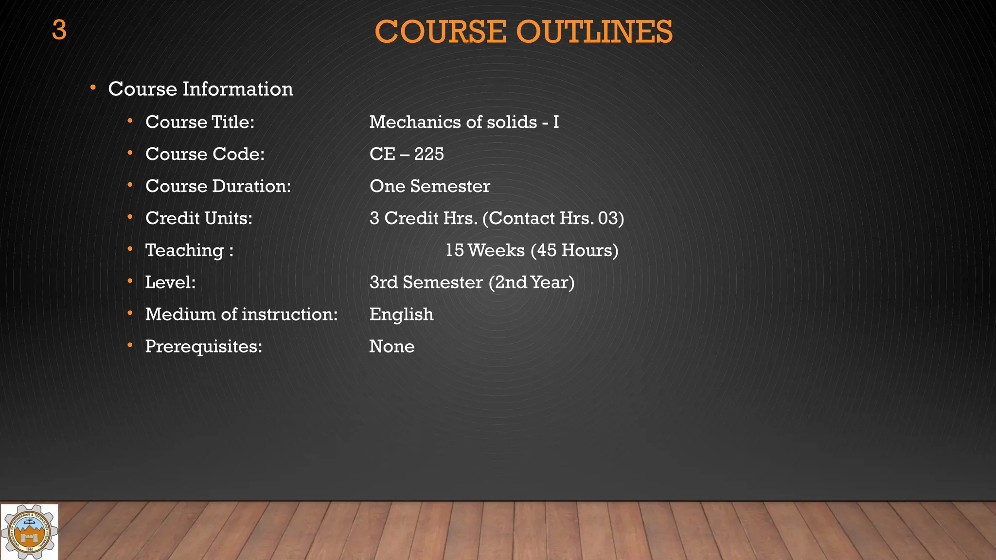
• CourseInformation
• Course Title: Mechanics of solids - I
• Course Code: CE – 225
• Course Duration: One Semester
• Credit Units: 3 Credit Hrs. (Contact Hrs. 03)
• Teaching : 15 Weeks (45 Hours)
• Level: 3rd Semester (2nd Year)
• Medium of instruction: English
• Prerequisites: None
3
4.
COURSE OUTLINES
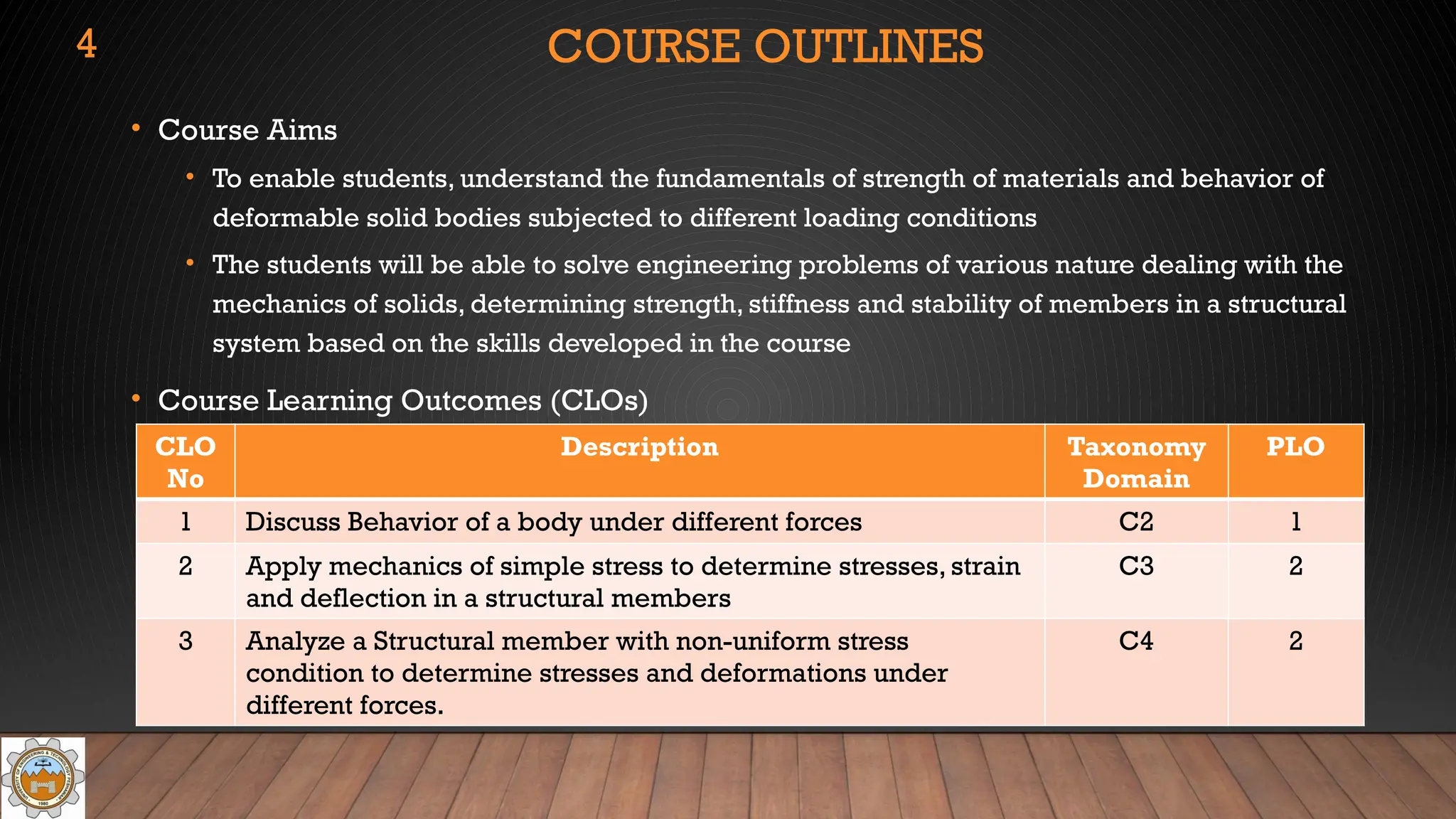
• CourseAims
• To enable students, understand the fundamentals of strength of materials and behavior of
deformable solid bodies subjected to different loading conditions
• The students will be able to solve engineering problems of various nature dealing with the
mechanics of solids, determining strength, stiffness and stability of members in a structural
system based on the skills developed in the course
• Course Learning Outcomes (CLOs)
CLO
No
Description Taxonomy
Domain
PLO
1 Discuss Behavior of a body under different forces C2 1
2 Apply mechanics of simple stress to determine stresses, strain
and deflection in a structural members
C3 2
3 Analyze a Structural member with non-uniform stress
condition to determine stresses and deformations under
different forces.
C4 2
4
5.
COURSE OUTLINES
• Teachingand Learning Activities (TLAs):
Course learning outcomes will be achieved through all or a suitable combination of the
following teaching strategies.
• Quizzes
• Classroom discussions
• In-class activities
• Homework assignments
• Self-study
• Mid-term major examination
• Final comprehensive examination
5
6.
COURSE OUTLINES
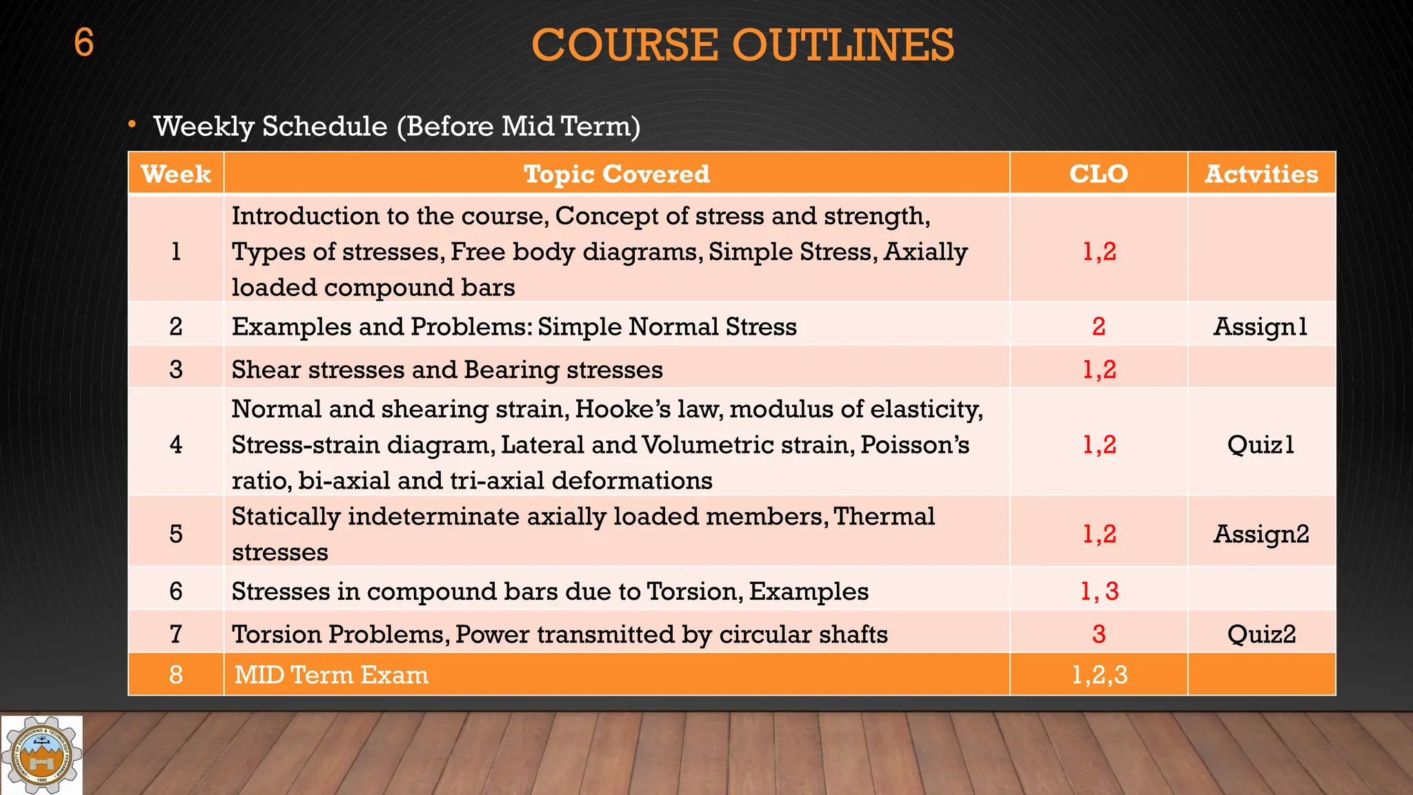
• WeeklySchedule (Before Mid Term)
Week Topic Covered CLO Actvities
1
Introduction to the course, Concept of stress and strength,
Types of stresses, Free body diagrams, Simple Stress, Axially
loaded compound bars
1,2
2 Examples and Problems: Simple Normal Stress 2 Assign1
3 Shear stresses and Bearing stresses 1,2
4
Normal and shearing strain, Hooke’s law, modulus of elasticity,
Stress-strain diagram, Lateral and Volumetric strain, Poisson’s
ratio, bi-axial and tri-axial deformations
1,2 Quiz1
5
Statically indeterminate axially loaded members,Thermal
stresses
1,2 Assign2
6 Stresses in compound bars due to Torsion, Examples 1, 3
7 Torsion Problems, Power transmitted by circular shafts 3 Quiz2
8 MID Term Exam 1,2,3
6
7.
COURSE OUTLINES
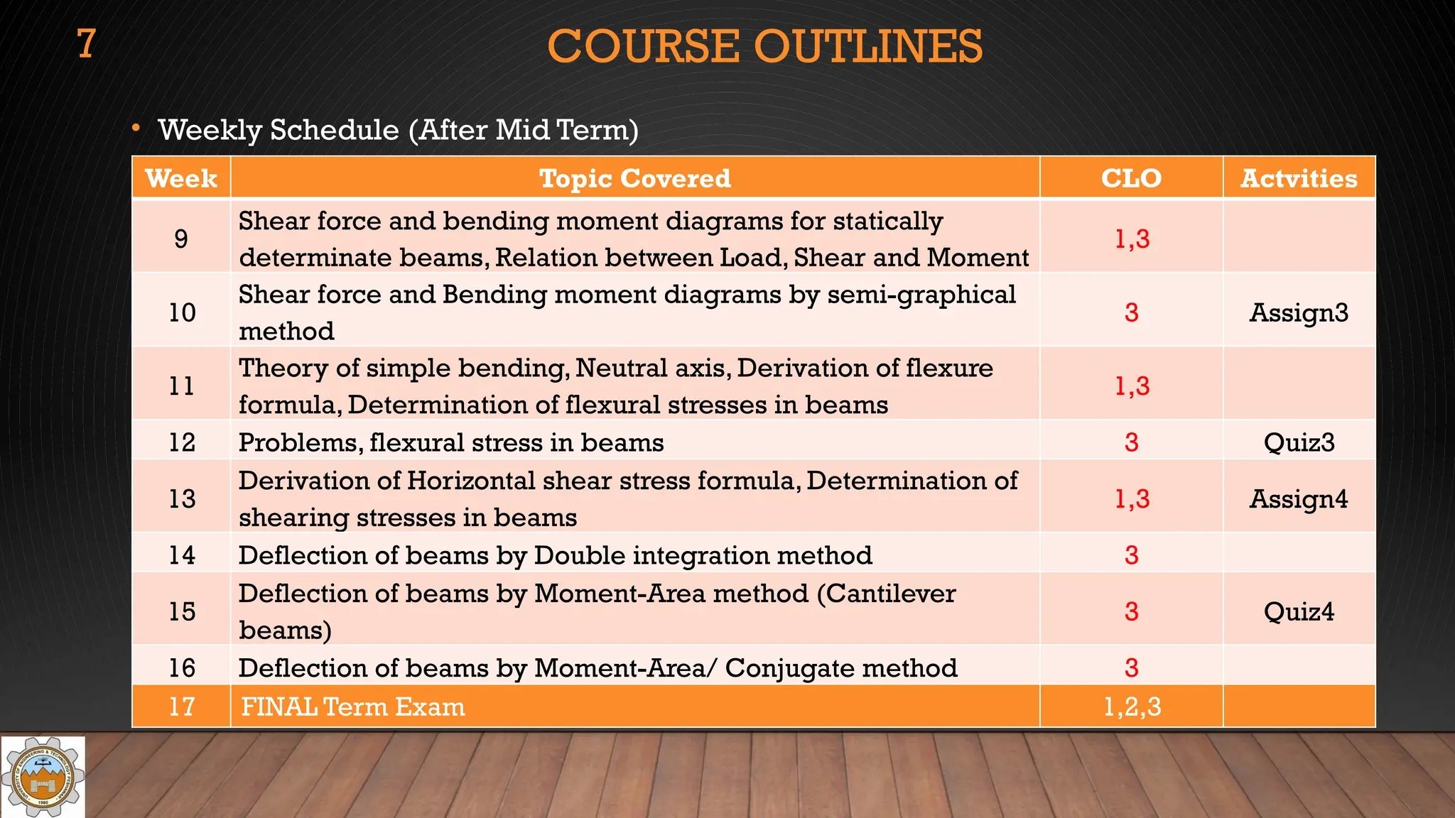
• WeeklySchedule (After Mid Term)
Week Topic Covered CLO Actvities
9
Shear force and bending moment diagrams for statically
determinate beams, Relation between Load, Shear and Moment
1,3
10
Shear force and Bending moment diagrams by semi-graphical
method
3 Assign3
11
Theory of simple bending, Neutral axis, Derivation of flexure
formula, Determination of flexural stresses in beams
1,3
12 Problems, flexural stress in beams 3 Quiz3
13
Derivation of Horizontal shear stress formula, Determination of
shearing stresses in beams
1,3 Assign4
14 Deflection of beams by Double integration method 3
15
Deflection of beams by Moment-Area method (Cantilever
beams)
3 Quiz4
16 Deflection of beams by Moment-Area/ Conjugate method 3
17 FINAL Term Exam 1,2,3
7
8.
COURSE OUTLINES
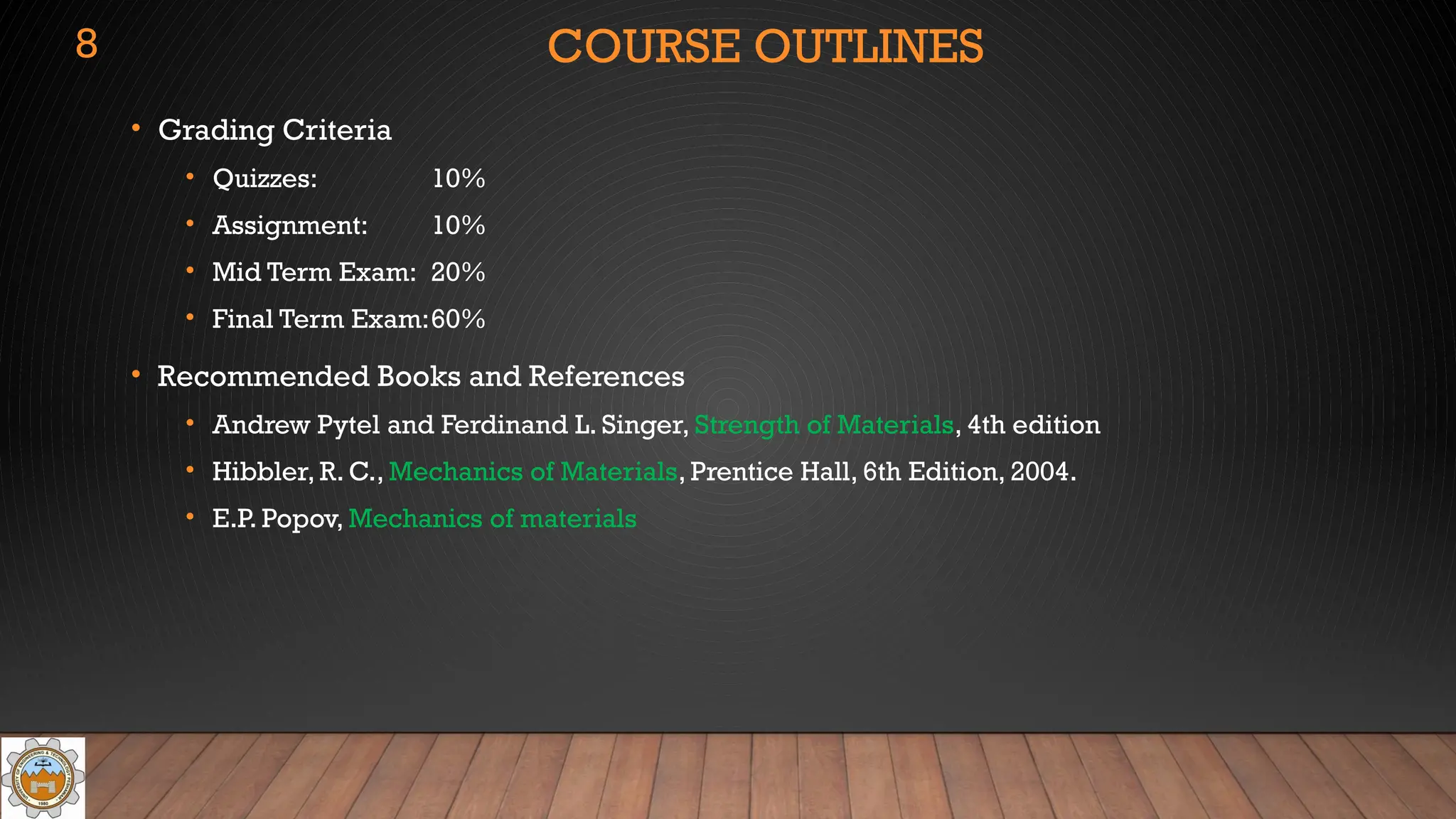
• GradingCriteria
• Quizzes: 10%
• Assignment: 10%
• Mid Term Exam: 20%
• Final Term Exam:60%
• Recommended Books and References
• Andrew Pytel and Ferdinand L. Singer, Strength of Materials, 4th edition
• Hibbler, R. C., Mechanics of Materials, Prentice Hall, 6th Edition, 2004.
• E.P. Popov, Mechanics of materials
8
9.
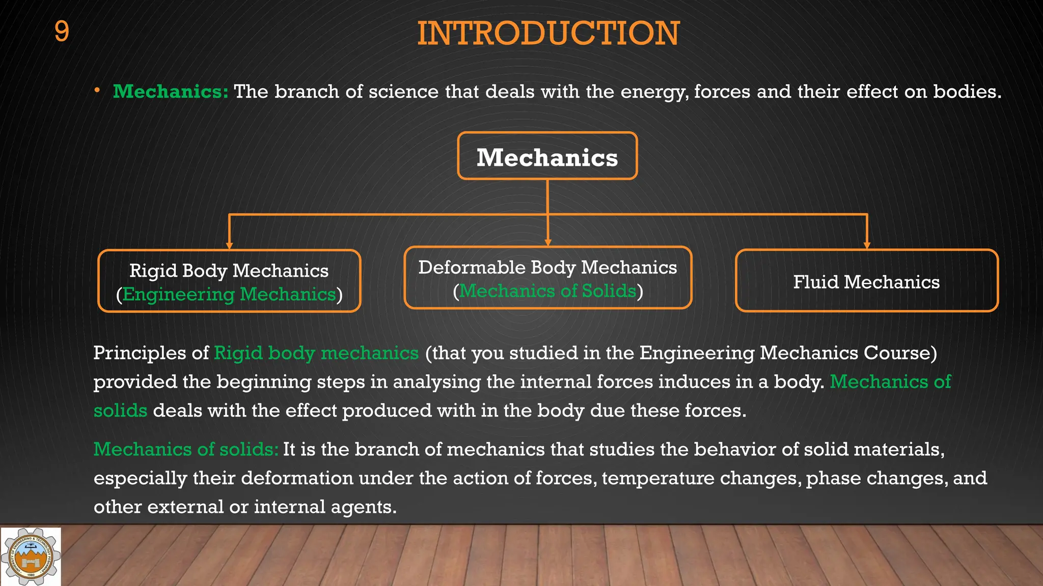
• Mechanics: Thebranch of science that deals with the energy, forces and their effect on bodies.
Principles of Rigid body mechanics (that you studied in the Engineering Mechanics Course)
provided the beginning steps in analysing the internal forces induces in a body. Mechanics of
solids deals with the effect produced with in the body due these forces.
Mechanics of solids: It is the branch of mechanics that studies the behavior of solid materials,
especially their deformation under the action of forces, temperature changes, phase changes, and
other external or internal agents.
Mechanics
INTRODUCTION
9
Rigid Body Mechanics
(Engineering Mechanics)
Deformable Body Mechanics
(Mechanics of Solids) Fluid Mechanics
10.
CONCEPT OF STRESS
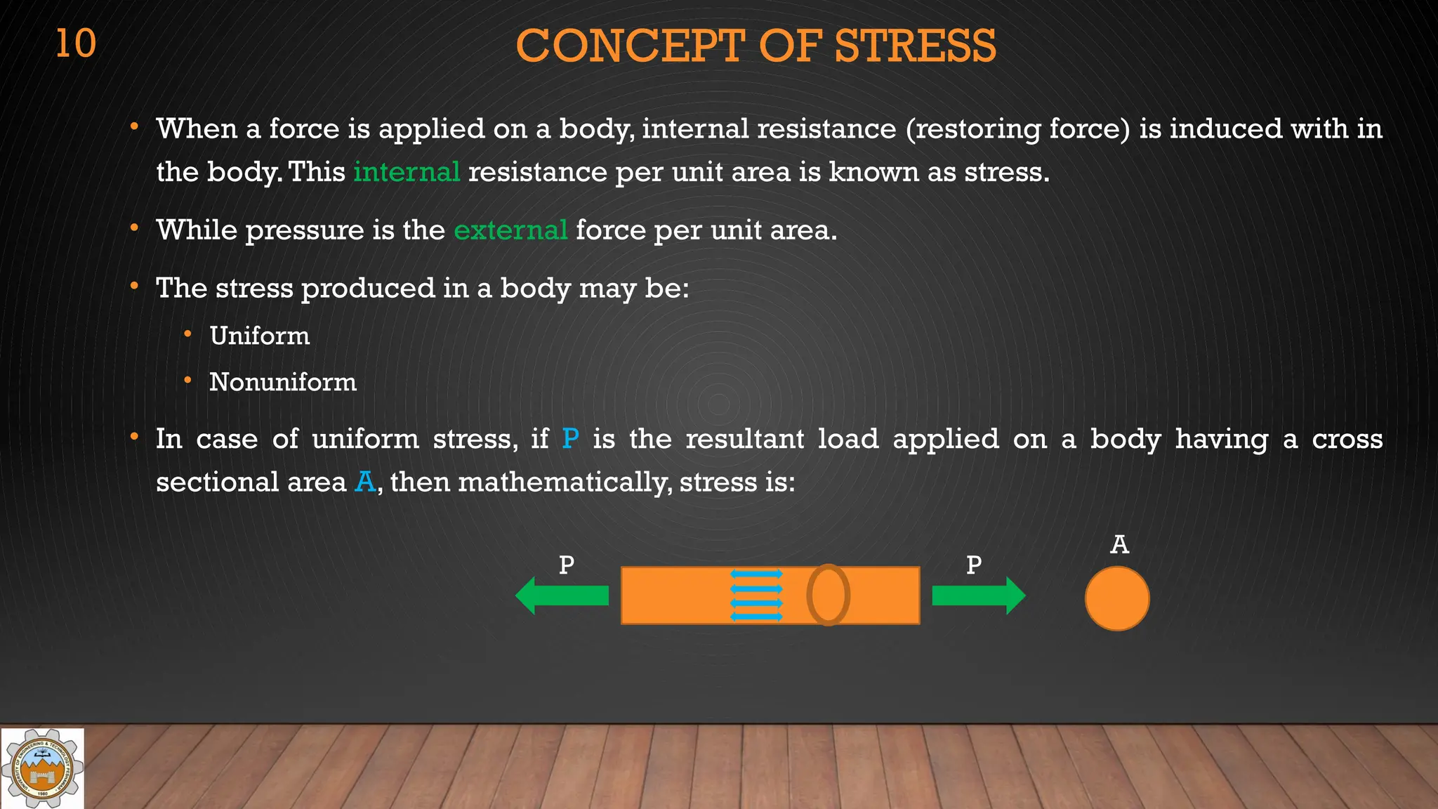
•When a force is applied on a body, internal resistance (restoring force) is induced with in
the body.This internal resistance per unit area is known as stress.
• While pressure is the external force per unit area.
• The stress produced in a body may be:
• Uniform
• Nonuniform
• In case of uniform stress, if P is the resultant load applied on a body having a cross
sectional area A, then mathematically, stress is:
P P
A
10
11.
CONCEPT OF STRESS(CONT..)
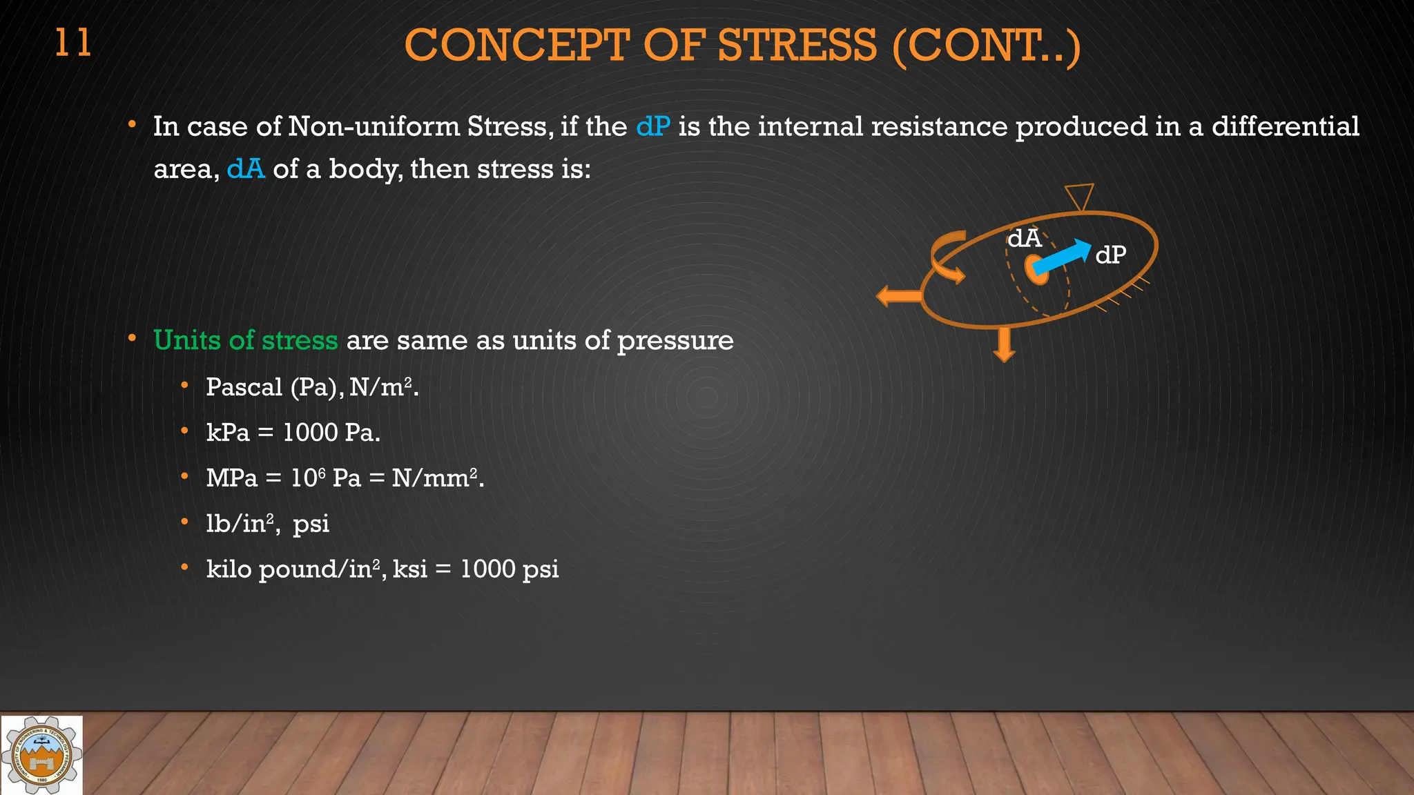
• In case of Non-uniform Stress, if the dP is the internal resistance produced in a differential
area, dA of a body, then stress is:
• Units of stress are same as units of pressure
• Pascal (Pa), N/m2
.
• kPa = 1000 Pa.
• MPa = 106
Pa = N/mm2
.
• lb/in2
, psi
• kilo pound/in2
, ksi = 1000 psi
dP
dA
11
12.
CONCEPT OF STRESS(CONT..)
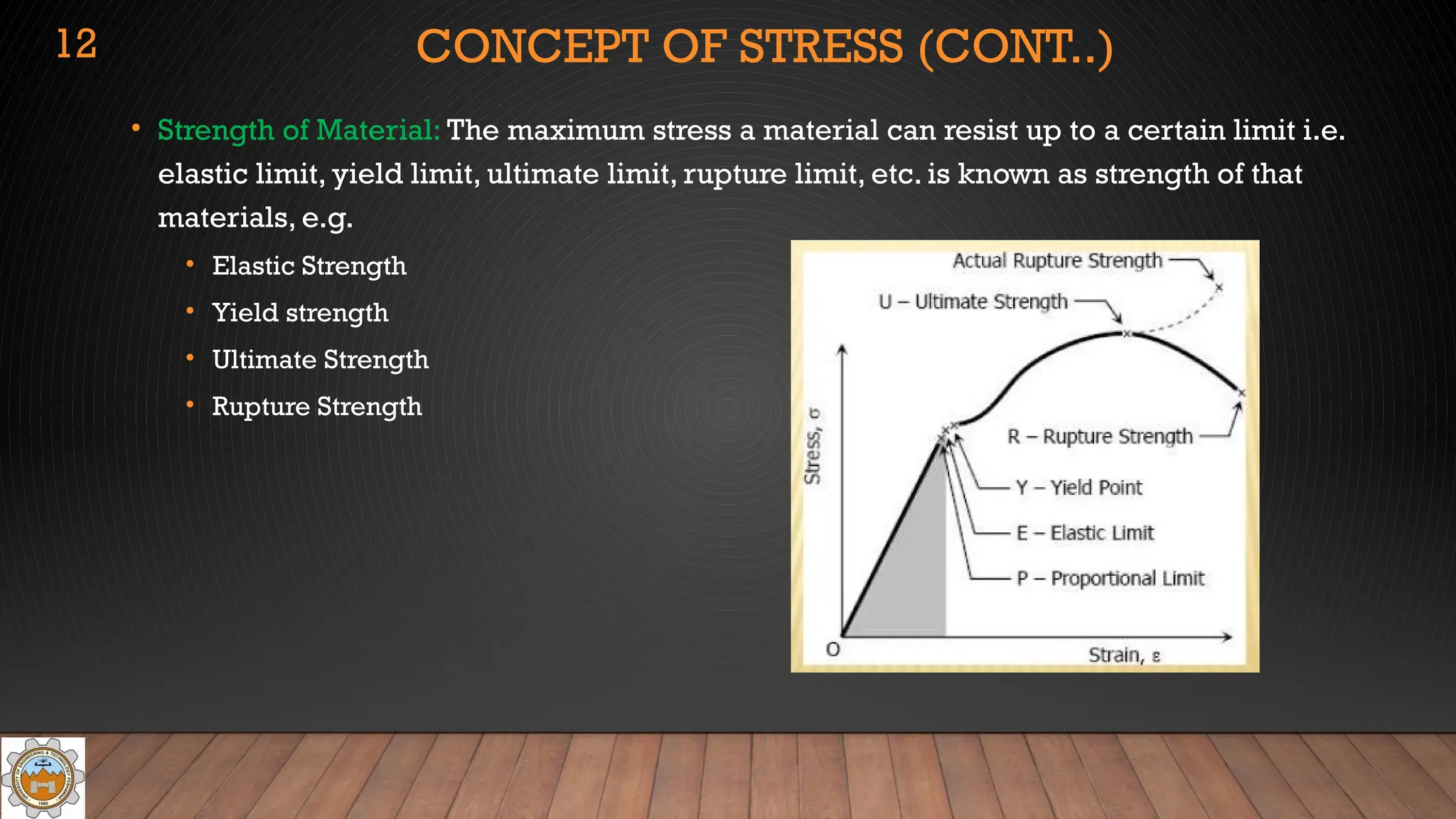
• Strength of Material: The maximum stress a material can resist up to a certain limit i.e.
elastic limit, yield limit, ultimate limit, rupture limit, etc. is known as strength of that
materials, e.g.
• Elastic Strength
• Yield strength
• Ultimate Strength
• Rupture Strength
12
13.
TYPES OF STRESSES
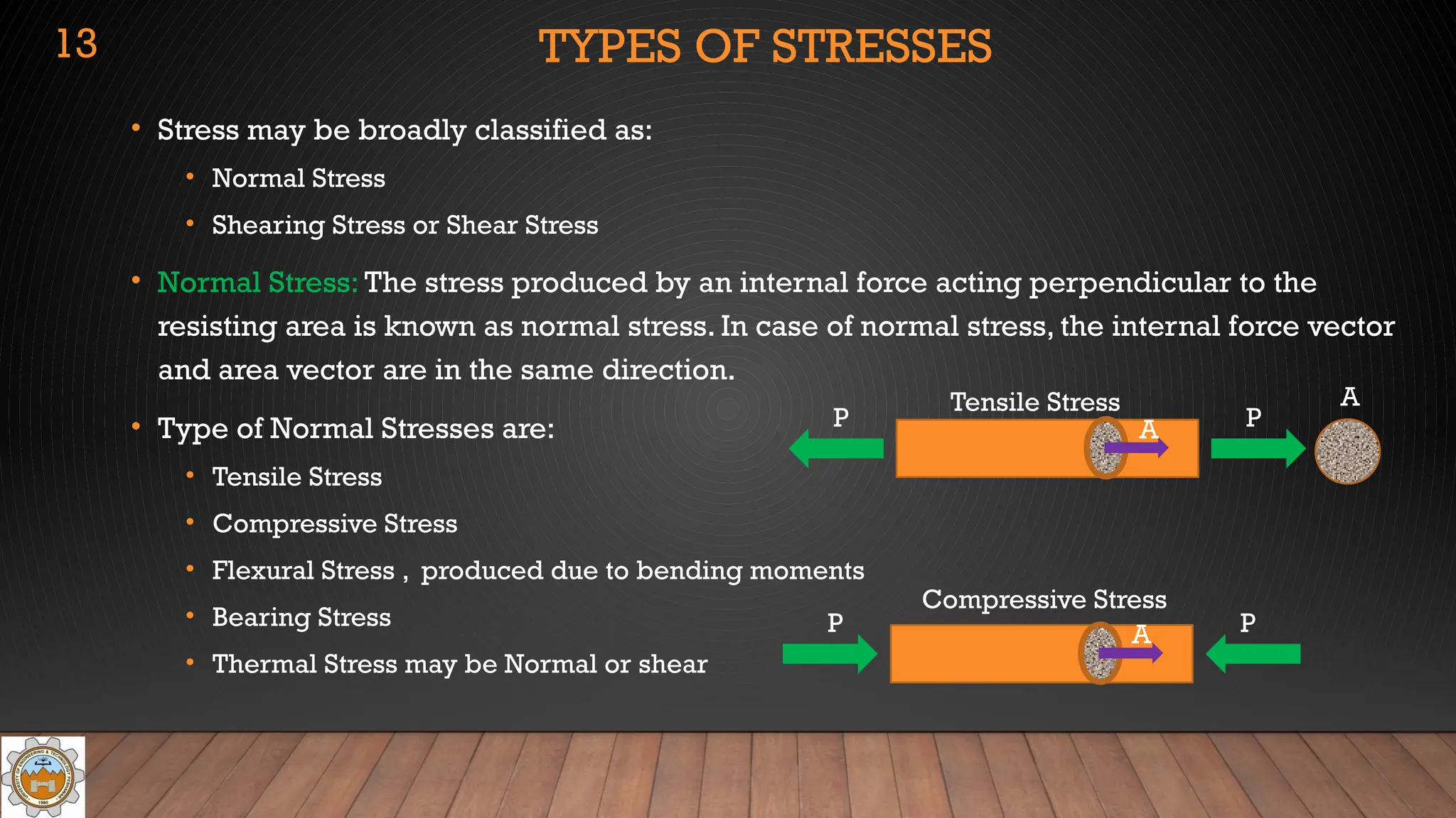
•Stress may be broadly classified as:
• Normal Stress
• Shearing Stress or Shear Stress
• Normal Stress: The stress produced by an internal force acting perpendicular to the
resisting area is known as normal stress. In case of normal stress, the internal force vector
and area vector are in the same direction.
• Type of Normal Stresses are:
• Tensile Stress
• Compressive Stress
• Flexural Stress , produced due to bending moments
• Bearing Stress
• Thermal Stress may be Normal or shear
P P
A
A
Tensile Stress
P P
A
Compressive Stress
13
14.
TYPES OD STRESSES(CONT..)
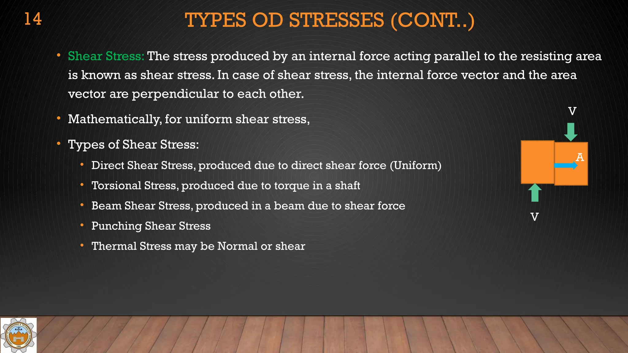
• Shear Stress: The stress produced by an internal force acting parallel to the resisting area
is known as shear stress. In case of shear stress, the internal force vector and the area
vector are perpendicular to each other.
• Mathematically, for uniform shear stress,
• Types of Shear Stress:
• Direct Shear Stress, produced due to direct shear force (Uniform)
• Torsional Stress, produced due to torque in a shaft
• Beam Shear Stress, produced in a beam due to shear force
• Punching Shear Stress
• Thermal Stress may be Normal or shear
A
V
V
14
15.
AXIALLY LOADED COMPOUNDBARS
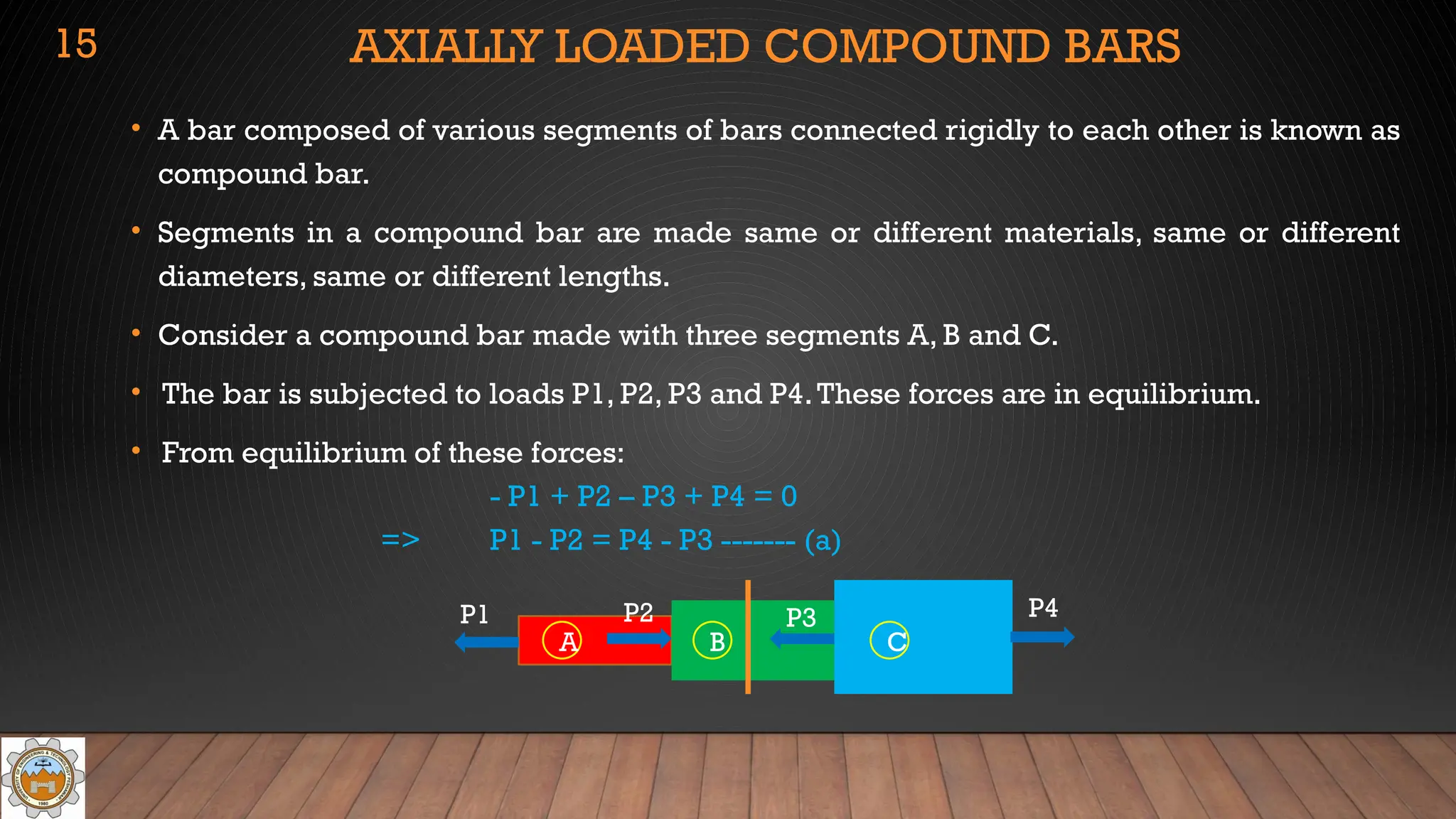
• A bar composed of various segments of bars connected rigidly to each other is known as
compound bar.
• Segments in a compound bar are made same or different materials, same or different
diameters, same or different lengths.
• Consider a compound bar made with three segments A, B and C.
• The bar is subjected to loads P1, P2, P3 and P4.These forces are in equilibrium.
• From equilibrium of these forces:
- P1 + P2 – P3 + P4 = 0
=> P1 - P2 = P4 - P3 ------- (a)
15
P1 P2 P3 P4
A B C
16.
AXIALLY LOADED COMPOUNDBARS (CONT..)
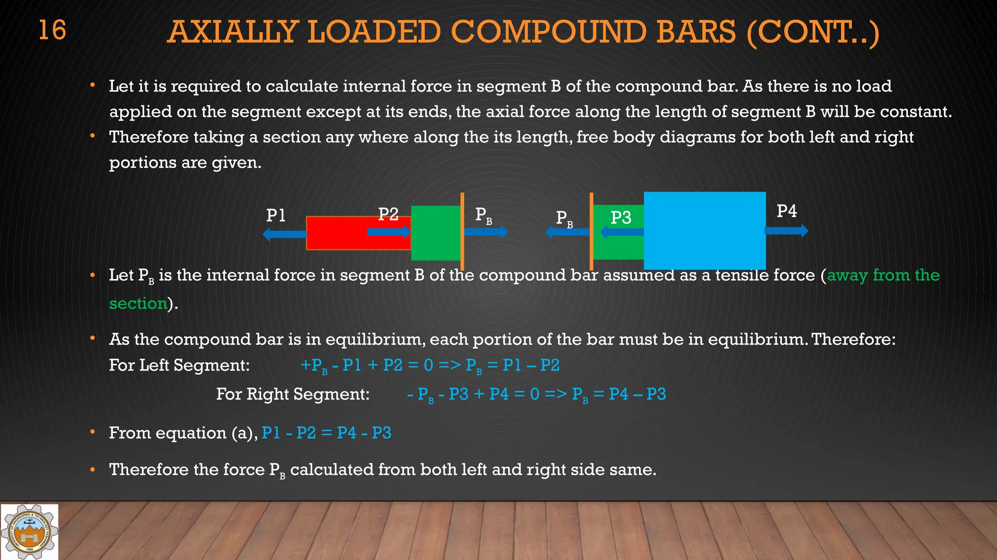
• Let it is required to calculate internal force in segment B of the compound bar. As there is no load
applied on the segment except at its ends, the axial force along the length of segment B will be constant.
• Therefore taking a section any where along the its length, free body diagrams for both left and right
portions are given.
• Let PB is the internal force in segment B of the compound bar assumed as a tensile force (away from the
section).
• As the compound bar is in equilibrium, each portion of the bar must be in equilibrium.Therefore:
For Left Segment: +PB - P1 + P2 = 0 => PB = P1 – P2
For Right Segment: - PB - P3 + P4 = 0 => PB = P4 – P3
• From equation (a), P1 - P2 = P4 - P3
• Therefore the force PB calculated from both left and right side same.
16
P1 P2 P3 P4
PB PB
17.
PROBLEM: SIMPLE STRESS
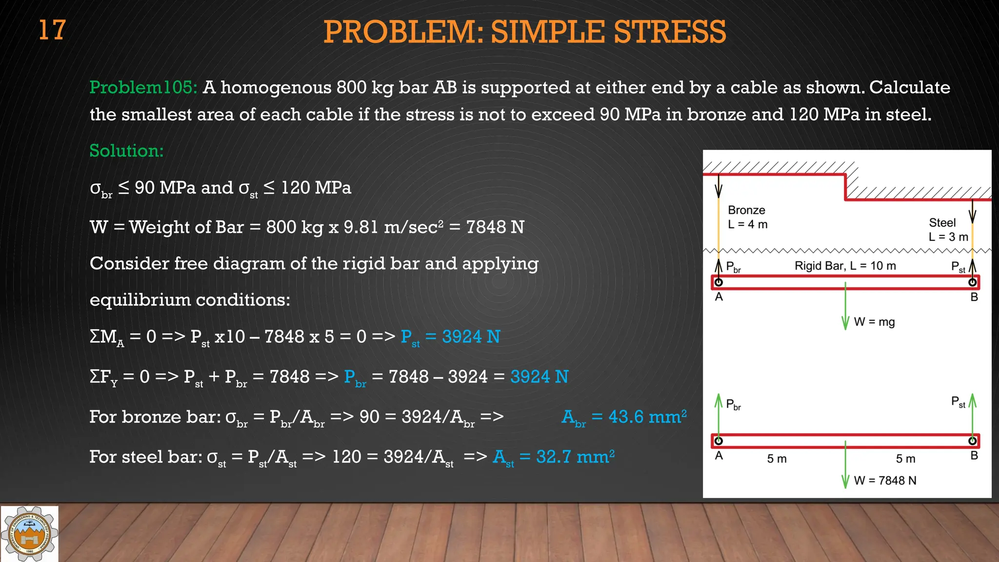
Problem105:A homogenous 800 kg bar AB is supported at either end by a cable as shown. Calculate
the smallest area of each cable if the stress is not to exceed 90 MPa in bronze and 120 MPa in steel.
Solution:
σbr ≤ 90 MPa and σst ≤ 120 MPa
W = Weight of Bar = 800 kg x 9.81 m/sec2
= 7848 N
Consider free diagram of the rigid bar and applying
equilibrium conditions:
M
Σ A = 0 => Pst x10 – 7848 x 5 = 0 => Pst = 3924 N
F
Σ Y = 0 => Pst + Pbr = 7848 => Pbr = 7848 – 3924 = 3924 N
For bronze bar: σbr = Pbr/Abr => 90 = 3924/Abr => Abr = 43.6 mm2
For steel bar: σst = Pst/Ast => 120 = 3924/Ast => Ast = 32.7 mm2
17
18.
PROBLEM: SIMPLE STRESS
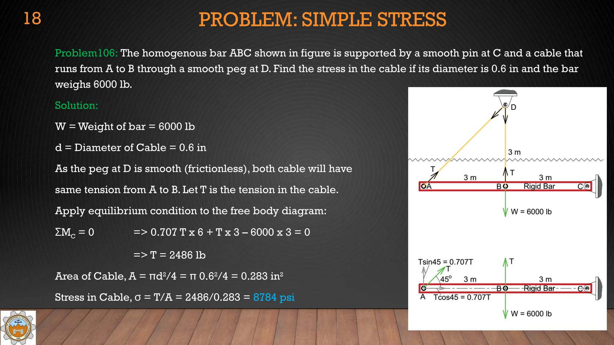
Problem106:The homogenous bar ABC shown in figure is supported by a smooth pin at C and a cable that
runs from A to B through a smooth peg at D. Find the stress in the cable if its diameter is 0.6 in and the bar
weighs 6000 lb.
Solution:
W = Weight of bar = 6000 lb
d = Diameter of Cable = 0.6 in
As the peg at D is smooth (frictionless), both cable will have
same tension from A to B. Let T is the tension in the cable.
Apply equilibrium condition to the free body diagram:
M
Σ C = 0 => 0.707 T x 6 + T x 3 – 6000 x 3 = 0
=> T = 2486 lb
Area of Cable, A = πd2
/4 = π 0.62
/4 = 0.283 in2
Stress in Cable, σ = T/A = 2486/0.283 = 8784 psi
18
19.
PROBLEM: SIMPLE STRESS
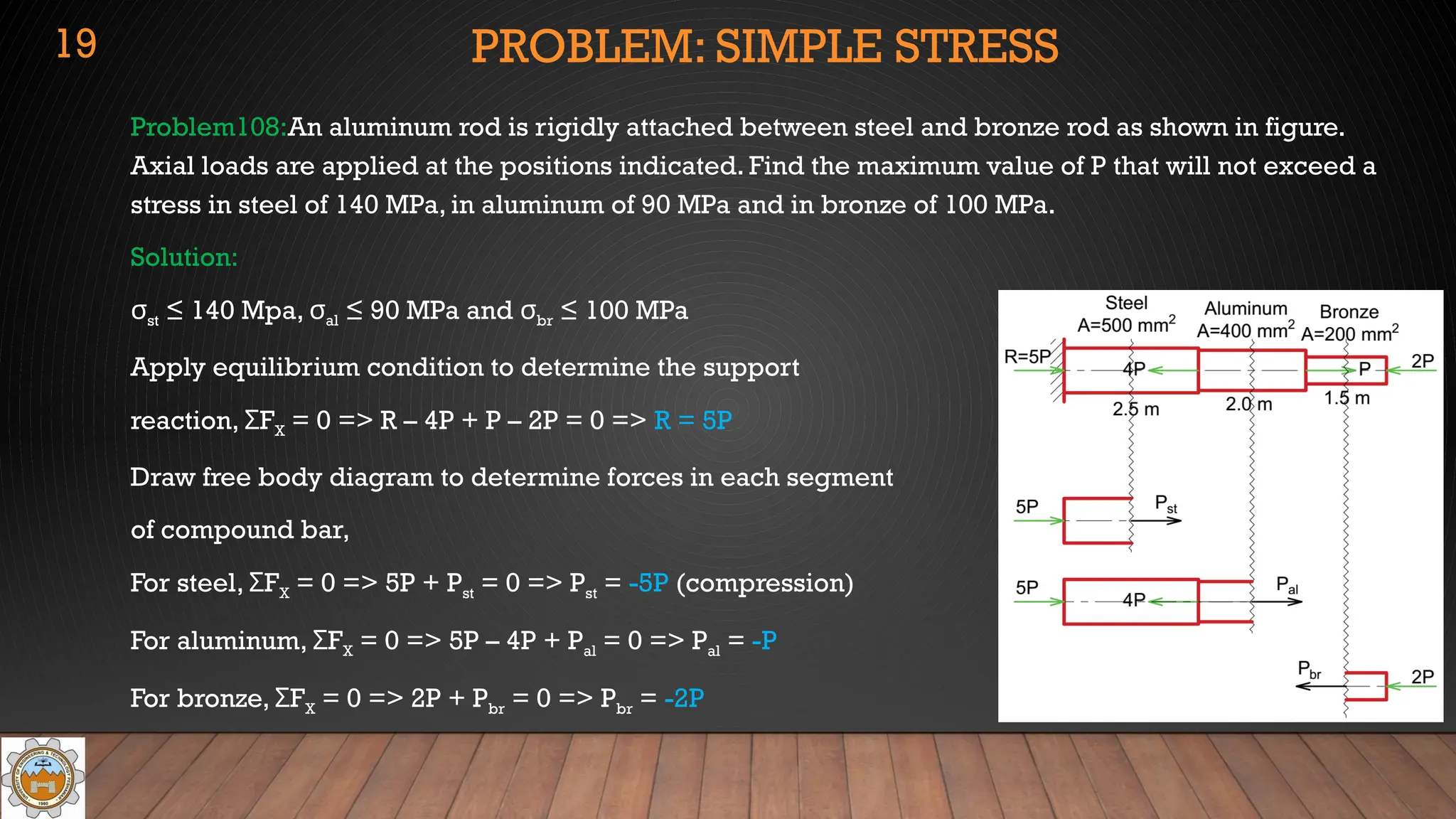
Problem108:Analuminum rod is rigidly attached between steel and bronze rod as shown in figure.
Axial loads are applied at the positions indicated. Find the maximum value of P that will not exceed a
stress in steel of 140 MPa, in aluminum of 90 MPa and in bronze of 100 MPa.
Solution:
σst ≤ 140 Mpa, σal ≤ 90 MPa and σbr ≤ 100 MPa
Apply equilibrium condition to determine the support
reaction, F
Σ X = 0 => R – 4P + P – 2P = 0 => R = 5P
Draw free body diagram to determine forces in each segment
of compound bar,
For steel, F
Σ X = 0 => 5P + Pst = 0 => Pst = -5P (compression)
For aluminum, F
Σ X = 0 => 5P – 4P + Pal = 0 => Pal = -P
For bronze, F
Σ X = 0 => 2P + Pbr = 0 => Pbr = -2P
19
20.
PROBLEM: SIMPLE STRESS
Problem108(Cont..):
If the stress in steel reaches its limiting stress in compression, then:
σst = |Pst/Ast| => 140 = 5P/500 => P = 14,000 N = 14 kN
Similarly, if the stress in aluminum reaches its limiting stress in compression, then:
σal = |Pal/Aal| => 90 = P/400 => P = 36,000 N = 36 kN
Similarly, if the stress in bronze reaches its limiting stress in compression, then:
σal = |Pal/Aal| => 100 = 2P/200 => P = 10,000 N = 10 kN
To keep the stresses with their limits in all three segments of the compound bars, the value
of P should the lowest in the above three calculated values of P.Therefore, the maximum
value of P will be, P = 10 kN
20
21.
PROBLEM: SIMPLE STRESS
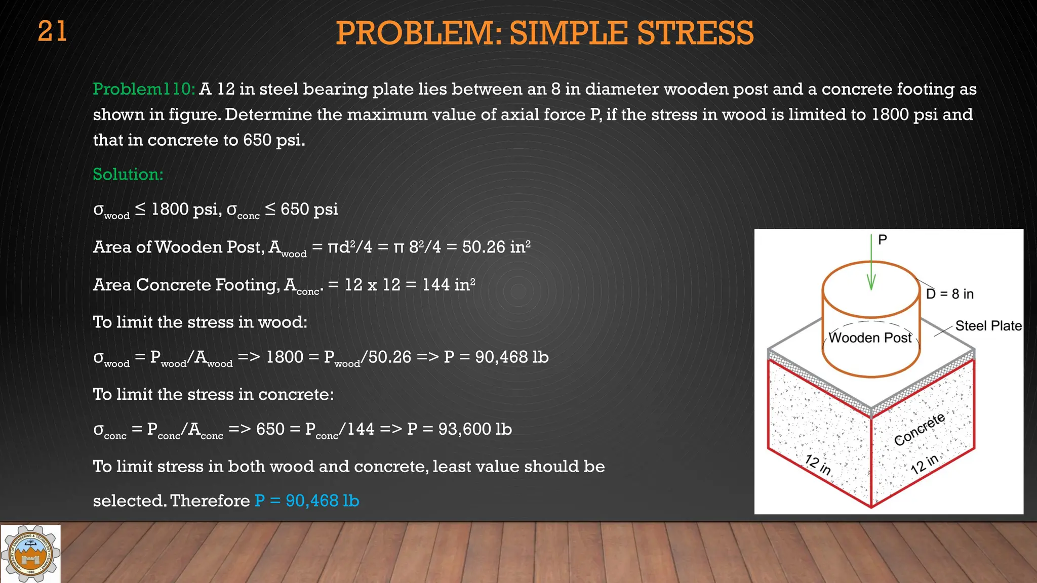
Problem110:A 12 in steel bearing plate lies between an 8 in diameter wooden post and a concrete footing as
shown in figure. Determine the maximum value of axial force P, if the stress in wood is limited to 1800 psi and
that in concrete to 650 psi.
Solution:
σwood ≤ 1800 psi, σconc ≤ 650 psi
Area of Wooden Post, Awood = πd2
/4 = π 82
/4 = 50.26 in2
Area Concrete Footing, Aconc. = 12 x 12 = 144 in2
To limit the stress in wood:
σwood = Pwood/Awood => 1800 = Pwood/50.26 => P = 90,468 lb
To limit the stress in concrete:
σconc = Pconc/Aconc => 650 = Pconc/144 => P = 93,600 lb
To limit stress in both wood and concrete, least value should be
selected.Therefore P = 90,468 lb
21
22.
UNIFORM SHEARING STRESS
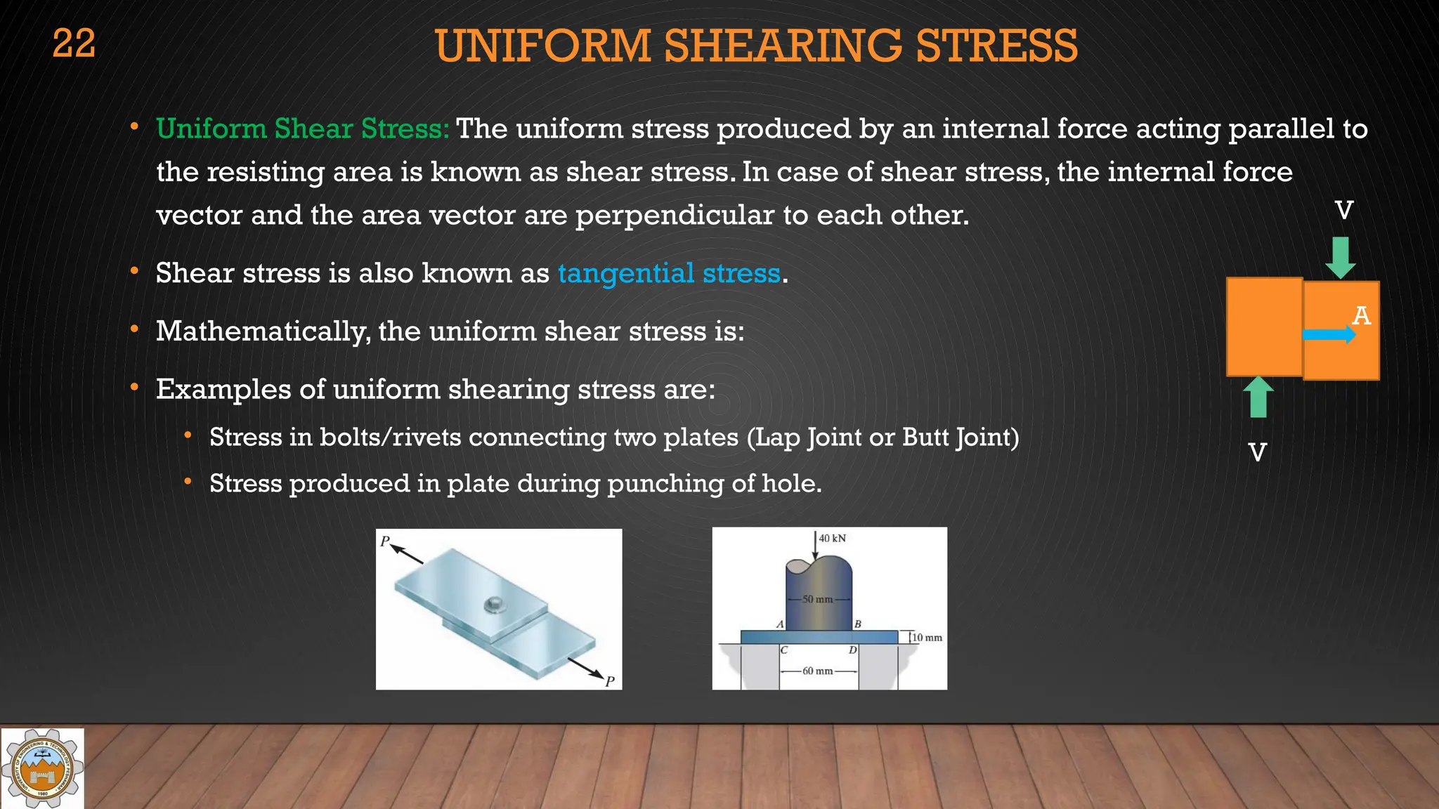
•Uniform Shear Stress: The uniform stress produced by an internal force acting parallel to
the resisting area is known as shear stress. In case of shear stress, the internal force
vector and the area vector are perpendicular to each other.
• Shear stress is also known as tangential stress.
• Mathematically, the uniform shear stress is:
• Examples of uniform shearing stress are:
• Stress in bolts/rivets connecting two plates (Lap Joint or Butt Joint)
• Stress produced in plate during punching of hole.
22
A
V
V
23.
UNIFORM SHEARING STRESS
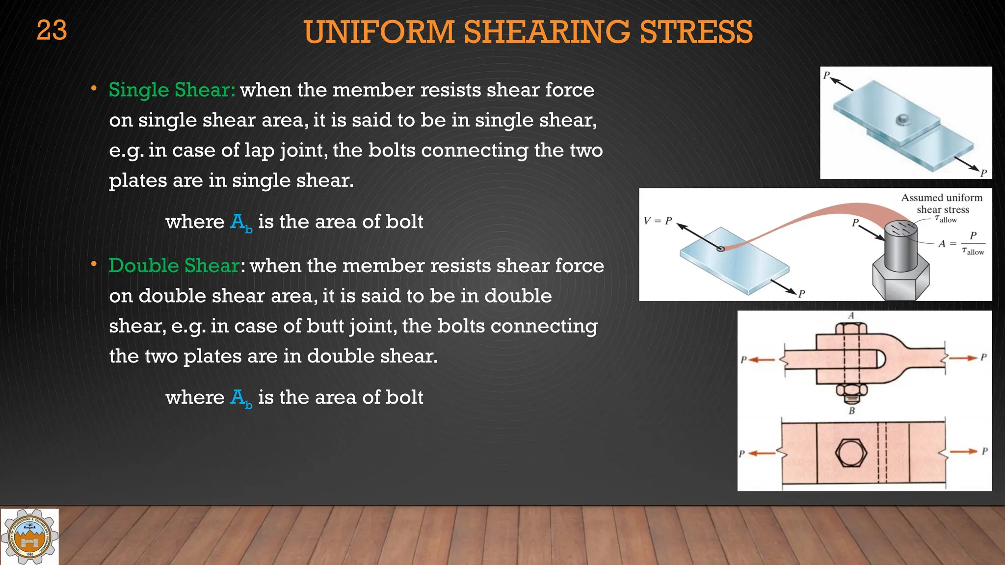
•Single Shear: when the member resists shear force
on single shear area, it is said to be in single shear,
e.g. in case of lap joint, the bolts connecting the two
plates are in single shear.
where Ab is the area of bolt
• Double Shear: when the member resists shear force
on double shear area, it is said to be in double
shear, e.g. in case of butt joint, the bolts connecting
the two plates are in double shear.
where Ab is the area of bolt
23
24.
UNIFORM SHEARING STRESS
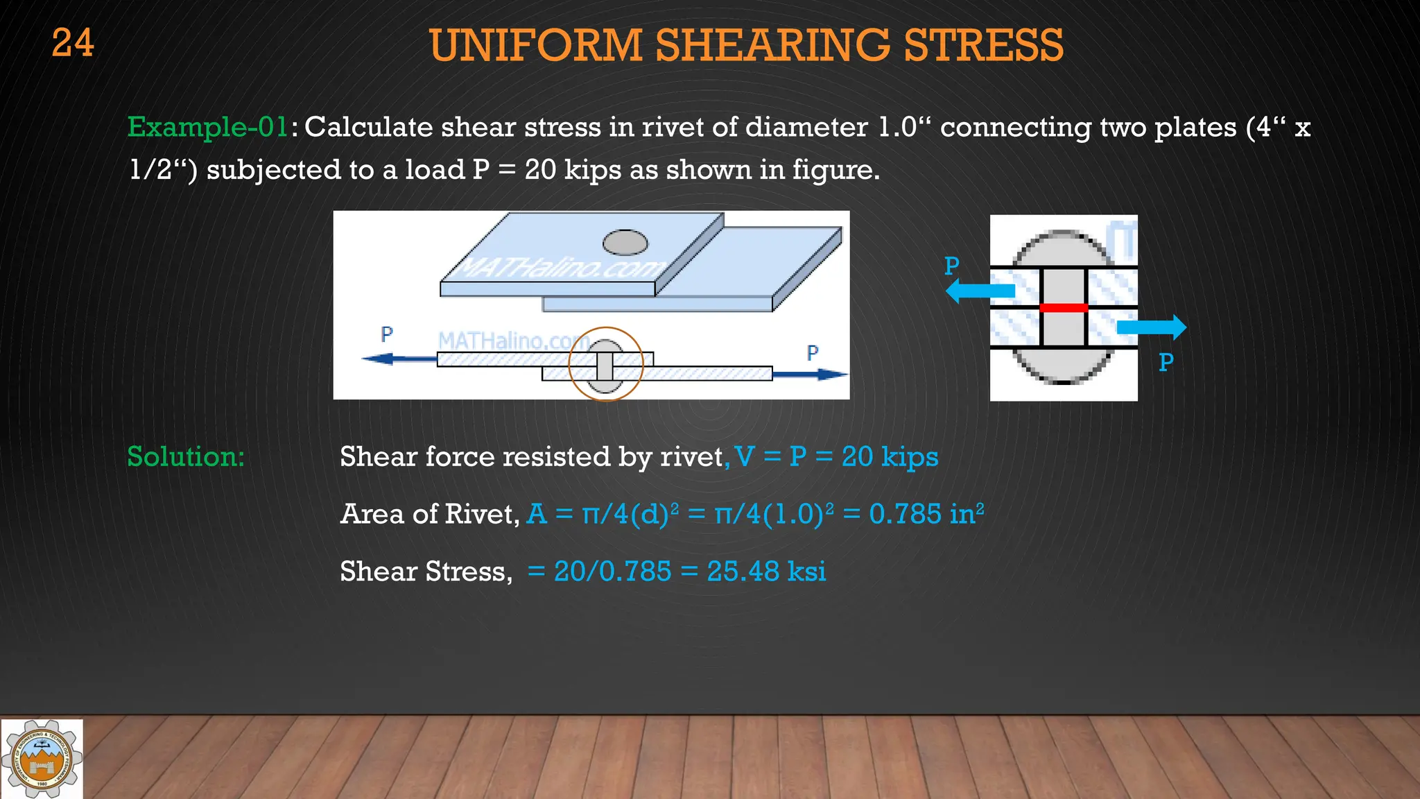
Example-01:Calculate shear stress in rivet of diameter 1.0“ connecting two plates (4“ x
1/2“) subjected to a load P = 20 kips as shown in figure.
Solution: Shear force resisted by rivet,V = P = 20 kips
Area of Rivet, A = π/4(d)2
= π/4(1.0)2
= 0.785 in2
Shear Stress, = 20/0.785 = 25.48 ksi
24
P
P
25.
UNIFORM SHEARING STRESS
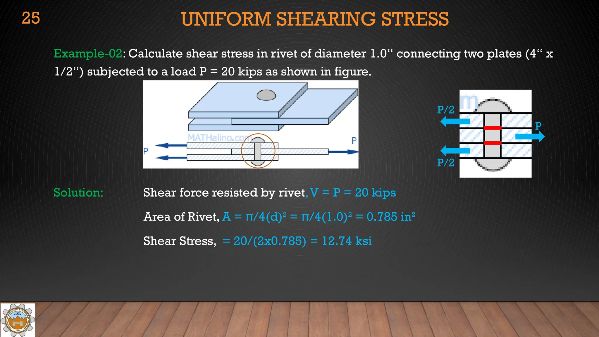
Example-02:Calculate shear stress in rivet of diameter 1.0“ connecting two plates (4“ x
1/2“) subjected to a load P = 20 kips as shown in figure.
Solution: Shear force resisted by rivet,V = P = 20 kips
Area of Rivet, A = π/4(d)2
= π/4(1.0)2
= 0.785 in2
Shear Stress, = 20/(2x0.785) = 12.74 ksi
25
P
P/2
P/2
26.
UNIFORM SHEARING STRESS
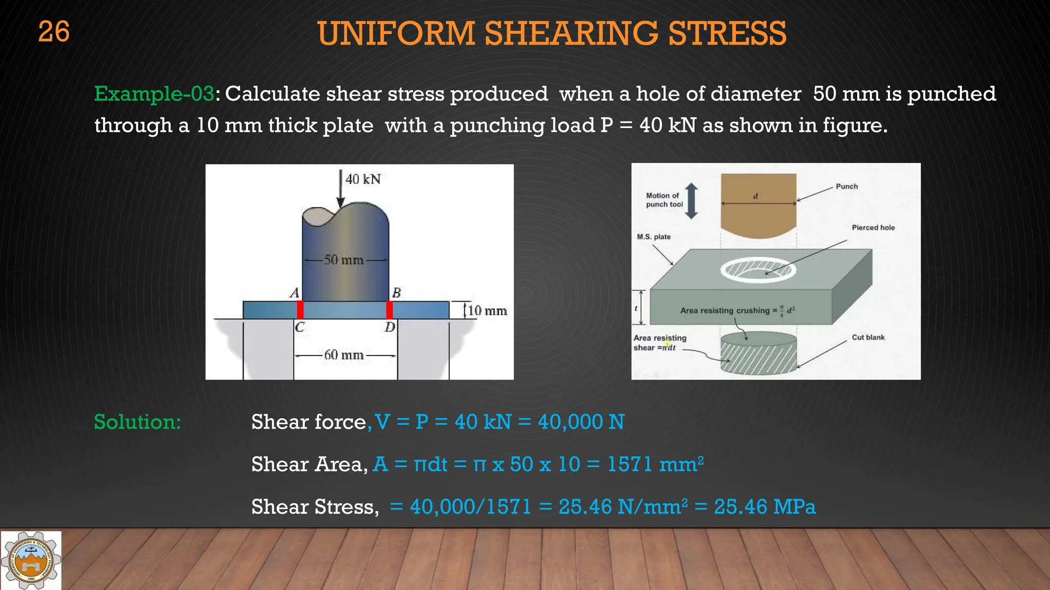
Example-03:Calculate shear stress produced when a hole of diameter 50 mm is punched
through a 10 mm thick plate with a punching load P = 40 kN as shown in figure.
Solution: Shear force,V = P = 40 kN = 40,000 N
Shear Area, A = πdt = π x 50 x 10 = 1571 mm2
Shear Stress, = 40,000/1571 = 25.46 N/mm2
= 25.46 MPa
26
27.
PROBLEMS: SHEARING STRESS
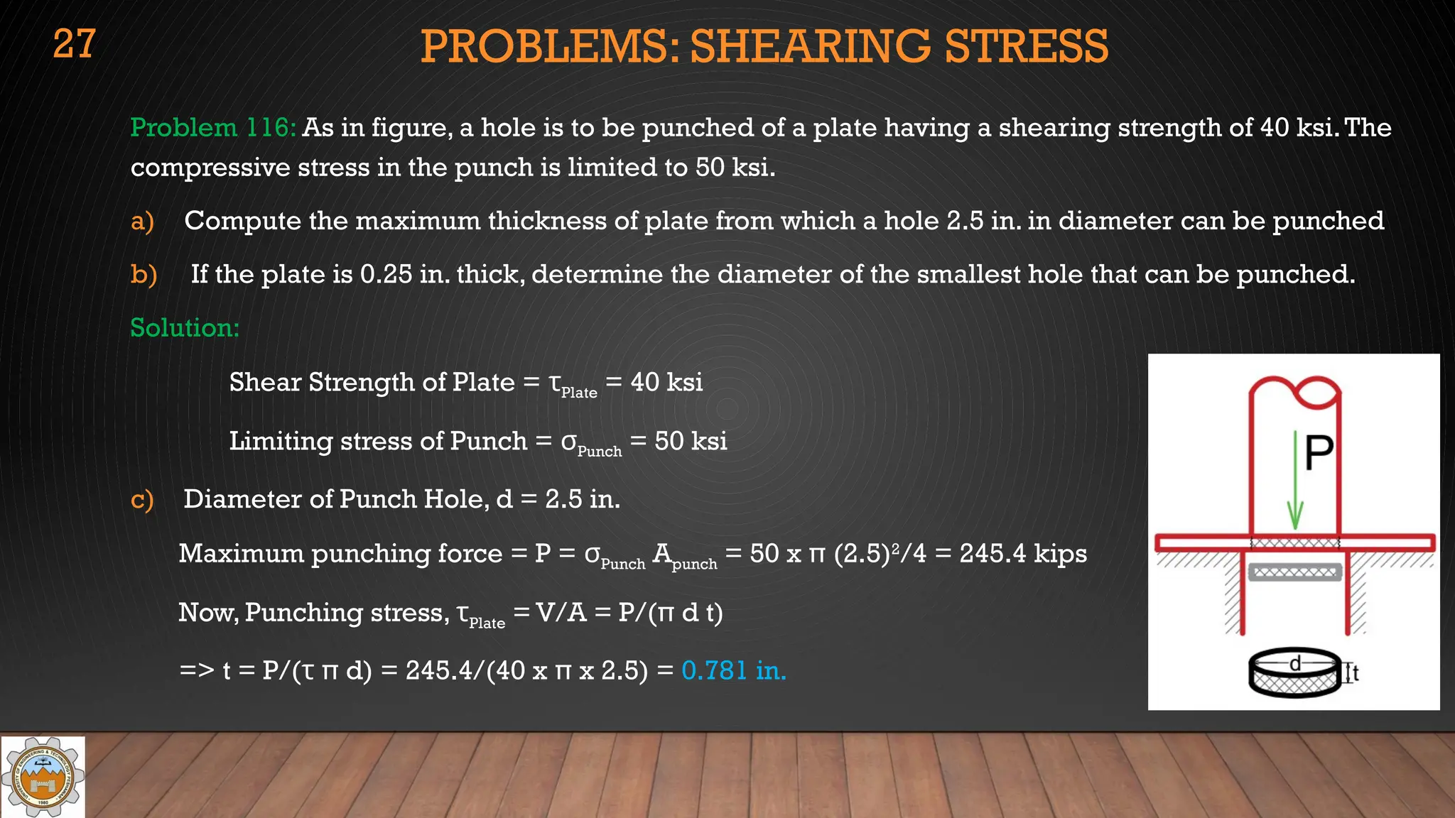
Problem116: As in figure, a hole is to be punched of a plate having a shearing strength of 40 ksi.The
compressive stress in the punch is limited to 50 ksi.
a) Compute the maximum thickness of plate from which a hole 2.5 in. in diameter can be punched
b) If the plate is 0.25 in. thick, determine the diameter of the smallest hole that can be punched.
Solution:
Shear Strength of Plate = τPlate = 40 ksi
Limiting stress of Punch = σPunch = 50 ksi
c) Diameter of Punch Hole, d = 2.5 in.
Maximum punching force = P = σPunch Apunch = 50 x π (2.5)2
/4 = 245.4 kips
Now, Punching stress, τPlate = V/A = P/(π d t)
=> t = P/(τ π d) = 245.4/(40 x π x 2.5) = 0.781 in.
27
28.
PROBLEMS: SHEARING STRESS
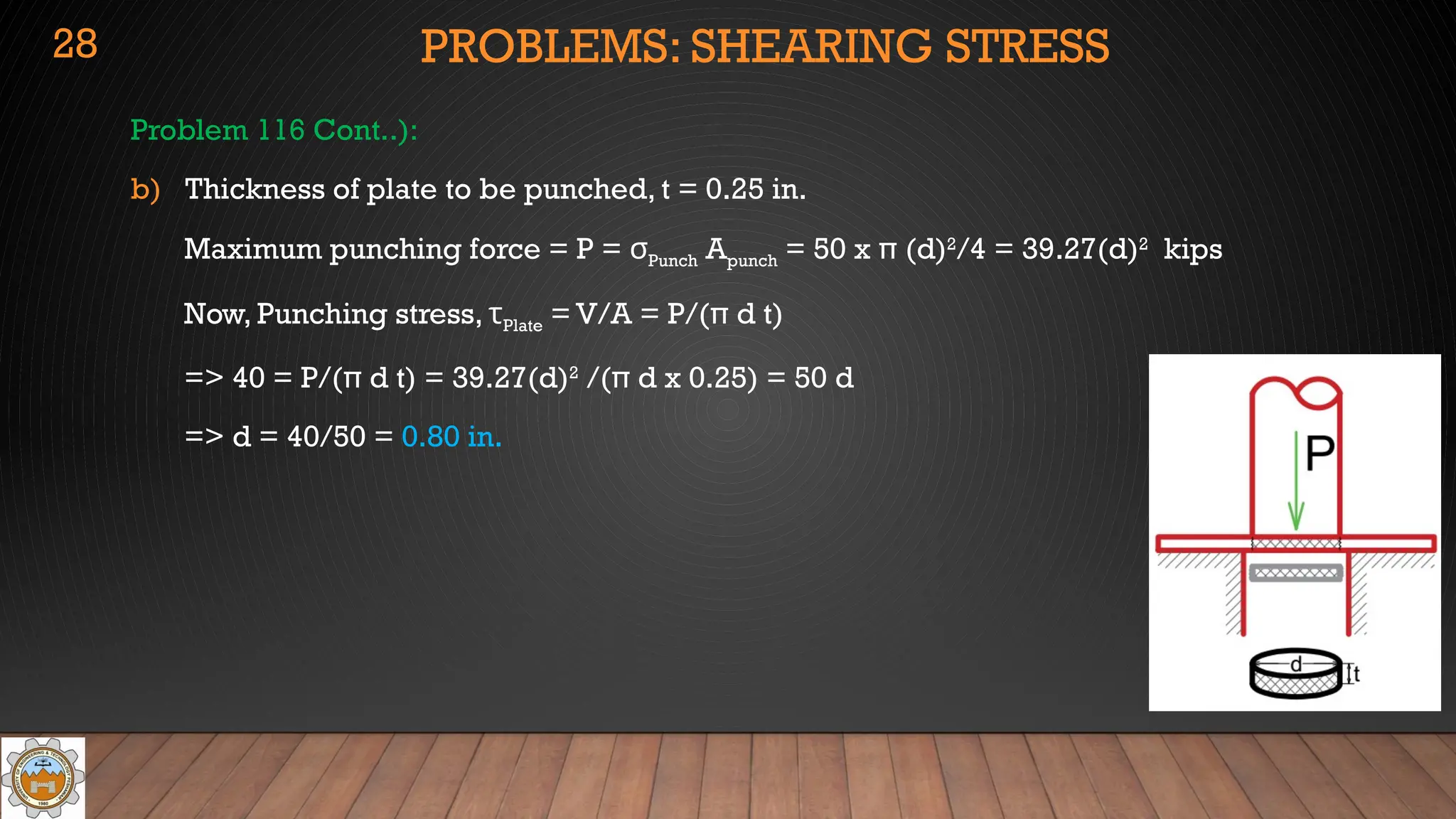
Problem116 Cont..):
b) Thickness of plate to be punched, t = 0.25 in.
Maximum punching force = P = σPunch Apunch = 50 x π (d)2
/4 = 39.27(d)2
kips
Now, Punching stress, τPlate = V/A = P/(π d t)
=> 40 = P/(π d t) = 39.27(d)2
/(π d x 0.25) = 50 d
=> d = 40/50 = 0.80 in.
28
29.
PROBLEMS: SHEARING STRESS
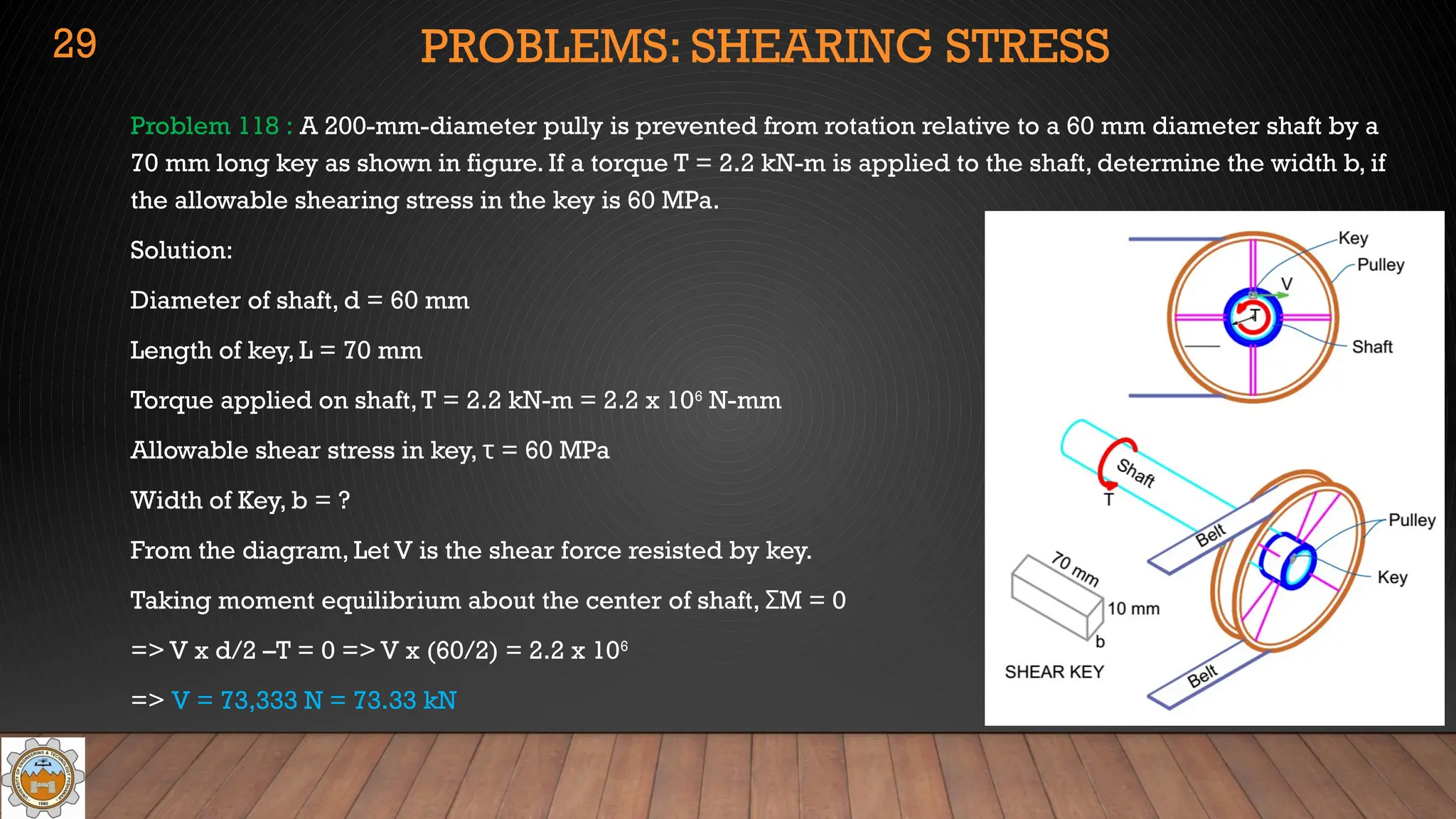
Problem118 : A 200-mm-diameter pully is prevented from rotation relative to a 60 mm diameter shaft by a
70 mm long key as shown in figure. If a torque T = 2.2 kN-m is applied to the shaft, determine the width b, if
the allowable shearing stress in the key is 60 MPa.
Solution:
Diameter of shaft, d = 60 mm
Length of key, L = 70 mm
Torque applied on shaft,T = 2.2 kN-m = 2.2 x 10⁶
N-mm
Allowable shear stress in key, τ = 60 MPa
Width of Key, b = ?
From the diagram, Let V is the shear force resisted by key.
Taking moment equilibrium about the center of shaft, M = 0
Σ
=> V x d/2 –T = 0 => V x (60/2) = 2.2 x 106
=> V = 73,333 N = 73.33 kN
29
30.
PROBLEMS: SHEARING STRESS
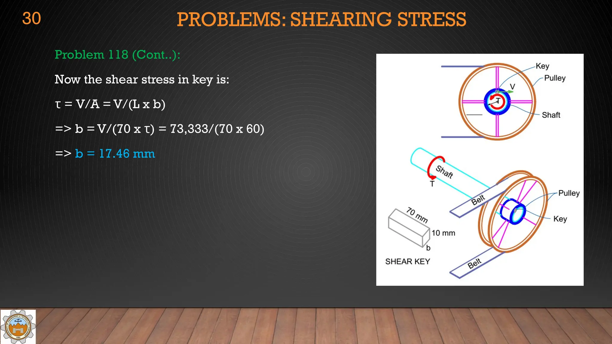
Problem118 (Cont..):
Now the shear stress in key is:
τ = V/A = V/(L x b)
=> b = V/(70 x τ) = 73,333/(70 x 60)
=> b = 17.46 mm
30
31.
PROBLEMS: SHEARING STRESS
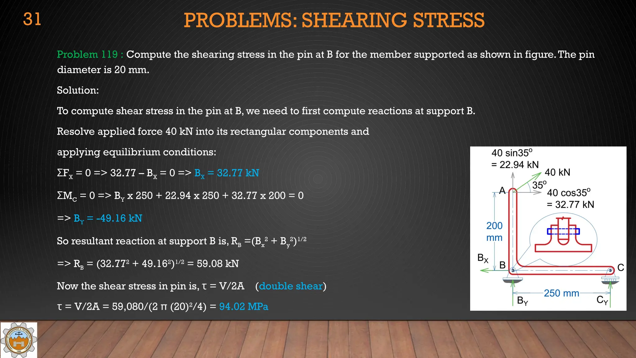
Problem119 : Compute the shearing stress in the pin at B for the member supported as shown in figure.The pin
diameter is 20 mm.
Solution:
To compute shear stress in the pin at B, we need to first compute reactions at support B.
Resolve applied force 40 kN into its rectangular components and
applying equilibrium conditions:
F
Σ X = 0 => 32.77 – BX = 0 => BX = 32.77 kN
M
Σ C = 0 => BY x 250 + 22.94 x 250 + 32.77 x 200 = 0
=> BY = -49.16 kN
So resultant reaction at support B is, RB =(Bx
2
+ By
2
)1/2
=> RB = (32.772
+ 49.162
)1/2
= 59.08 kN
Now the shear stress in pin is, τ = V/2A (double shear)
τ = V/2A = 59,080/(2 π (20)2
/4) = 94.02 MPa
31
32.
PROBLEMS: SHEARING STRESS
Problem121 : Referring to figure, compute the maximum force P that can apply by the machine operator if the
shearing stress in the pin at B and the axial stress in the control rod at C are limited to 4000 psi and 5000 psi
respectively.The diameters are 0.25 in for the pin and 0.50 in for the rod. Assume single shear for the pin at B.
Solution:
τpin ≤ 4000 psi, σrod ≤ 5000 psi
dpin =0.25 in, drod = 0.50 in.
Resolving Tension in rod into its rectangular components,
and applying equilibrium conditions:
M
Σ B = 0 => P x 6 –T sin(10) x 2 = 0 => T = 17.276 P (a)
F
Σ X = 0 => Tcos10 – BX = 0=> BX = 0.9848 T
M
Σ C = 0 => P x 8 – BY x 2 = 0 => BY = 4P
Shear force in pin is,V = (Bx
2
+ By
2
)1/2
= [(0.9848T)2
+ (4P)2
]1/2
(b)
32
33.
PROBLEMS: SHEARING STRESS
Problem121 (Cont..):
Putting value of T from equation (a) into equation (b)
V = [(0.9848T)2
+ (4P)2
]1/2
= [(17.013P)2
+ (4P)2
]1/2
= 17.477 P
Now limiting shear stress in pin, τ = V/A (single shear)
=> 4000 = 17.477 P/(π (0.25)2
/4)
=> P = 11.23 lb
Now limiting axial stress in rod, = T/A
σ
=> 5000 = 17.276P/ /(π (0.5)2
/4) from equation (a)
=> P = 56.83 lb
To limit both stress simultaneously, least value of P should be selected,
P = 11.23 lb
33
34.
BEARING STRESS
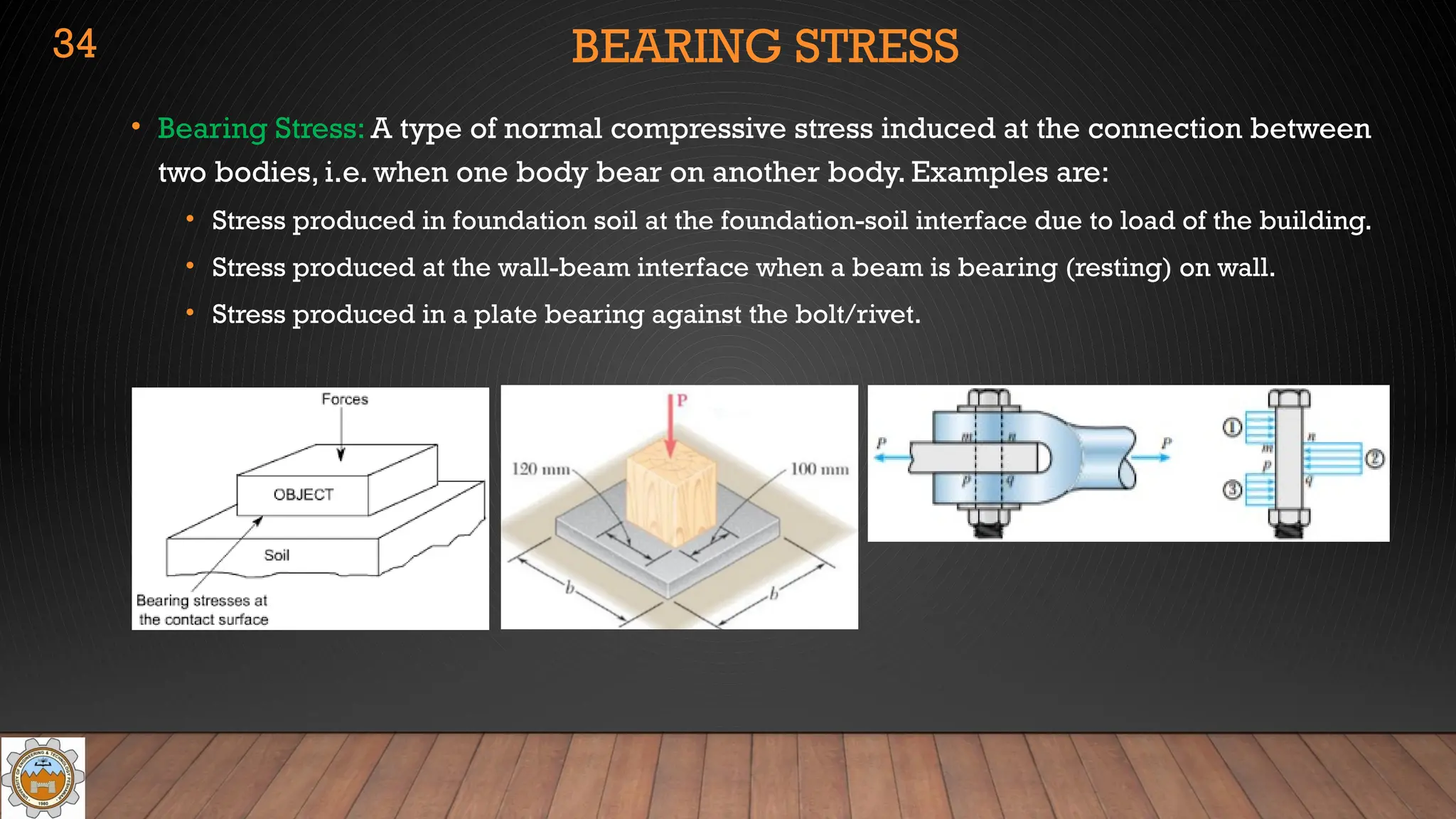
• BearingStress: A type of normal compressive stress induced at the connection between
two bodies, i.e. when one body bear on another body. Examples are:
• Stress produced in foundation soil at the foundation-soil interface due to load of the building.
• Stress produced at the wall-beam interface when a beam is bearing (resting) on wall.
• Stress produced in a plate bearing against the bolt/rivet.
34
35.
BEARING STRESS
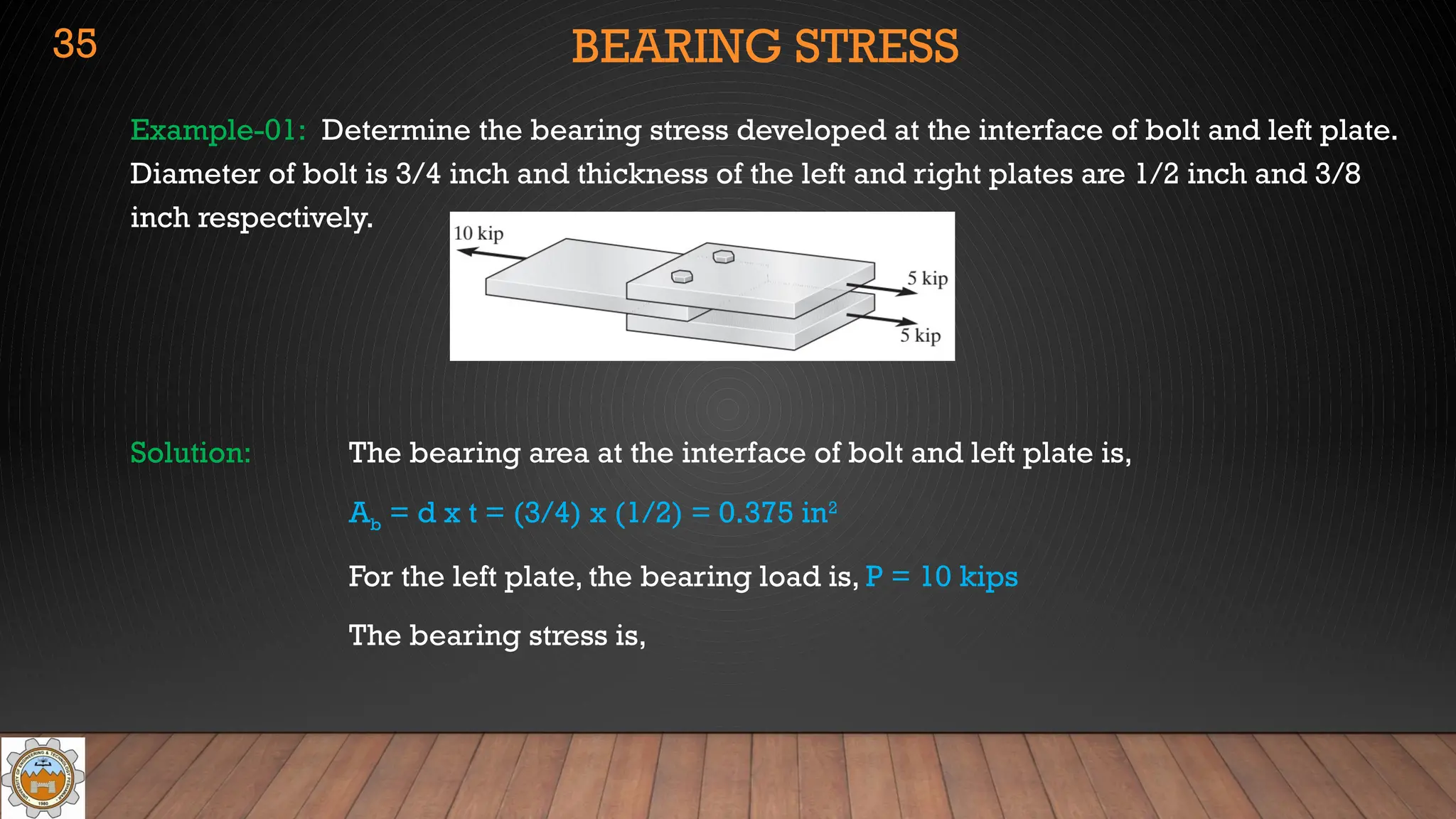
Example-01: Determinethe bearing stress developed at the interface of bolt and left plate.
Diameter of bolt is 3/4 inch and thickness of the left and right plates are 1/2 inch and 3/8
inch respectively.
Solution: The bearing area at the interface of bolt and left plate is,
Ab = d x t = (3/4) x (1/2) = 0.375 in2
For the left plate, the bearing load is, P = 10 kips
The bearing stress is,
35
36.
BEARING STRESS
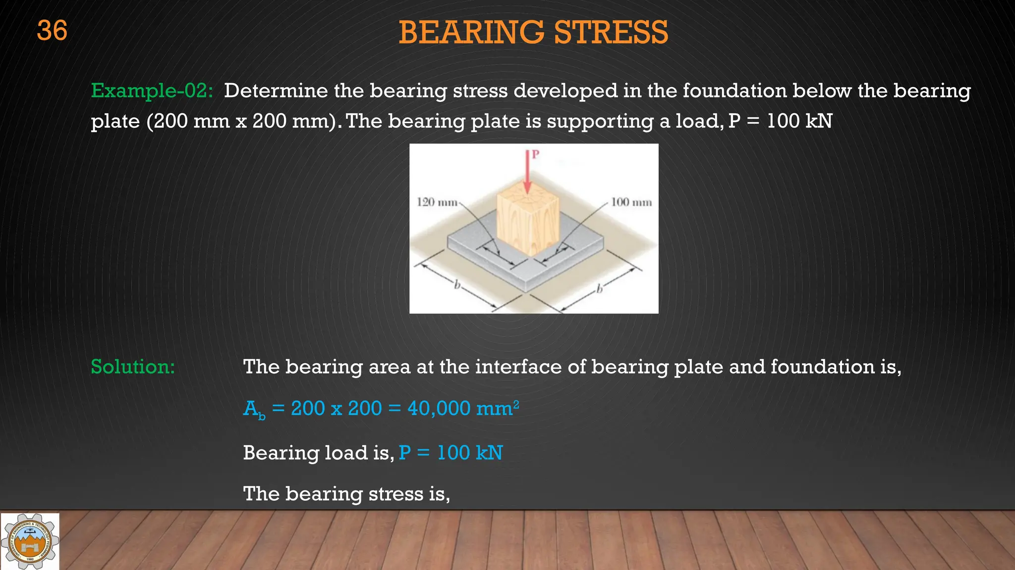
Example-02: Determinethe bearing stress developed in the foundation below the bearing
plate (200 mm x 200 mm).The bearing plate is supporting a load, P = 100 kN
Solution: The bearing area at the interface of bearing plate and foundation is,
Ab = 200 x 200 = 40,000 mm2
Bearing load is, P = 100 kN
The bearing stress is,
36
37.
PROBLEMS: BEARING STRESS
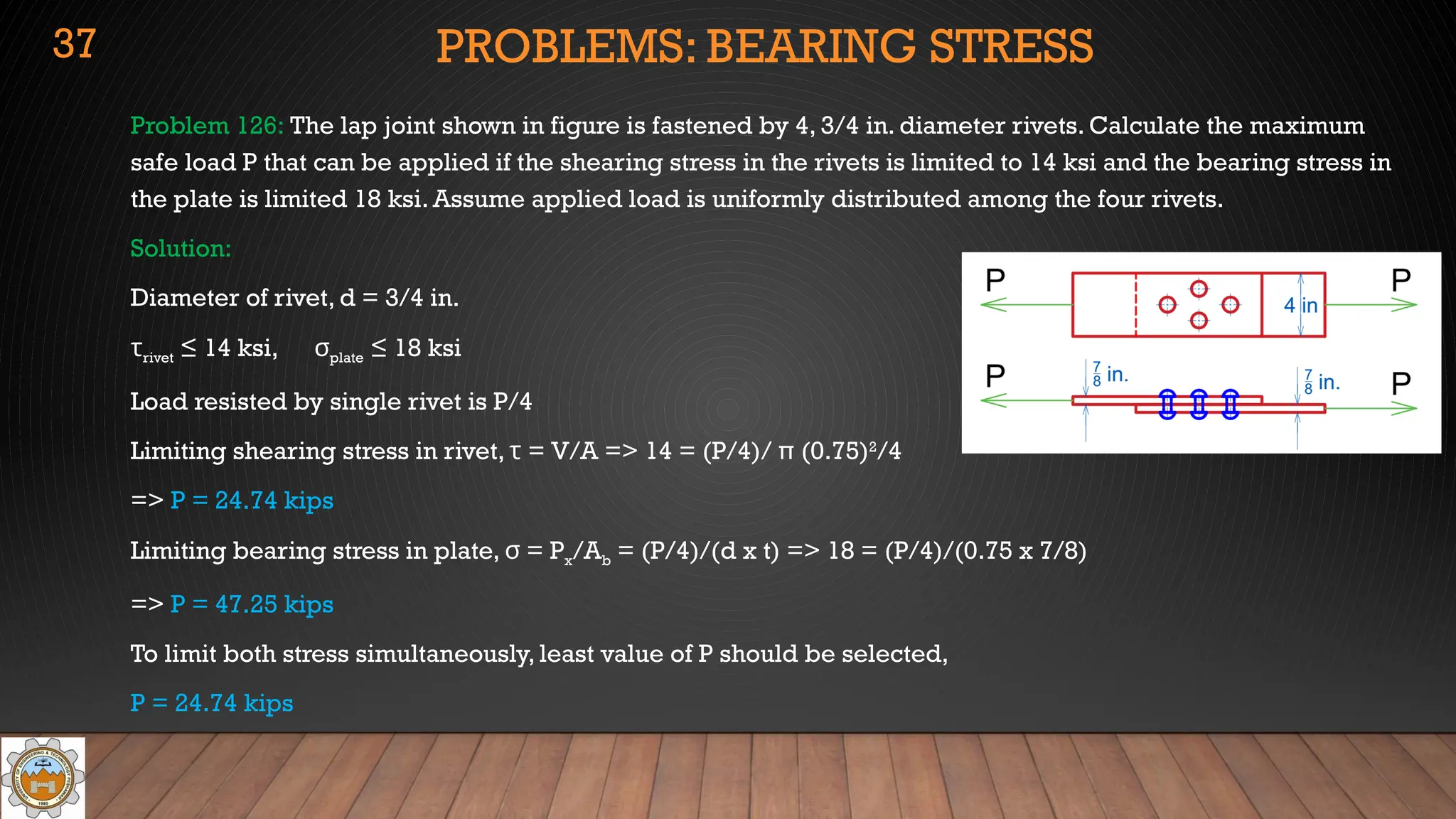
Problem126: The lap joint shown in figure is fastened by 4, 3/4 in. diameter rivets. Calculate the maximum
safe load P that can be applied if the shearing stress in the rivets is limited to 14 ksi and the bearing stress in
the plate is limited 18 ksi. Assume applied load is uniformly distributed among the four rivets.
Solution:
Diameter of rivet, d = 3/4 in.
τrivet ≤ 14 ksi, σplate ≤ 18 ksi
Load resisted by single rivet is P/4
Limiting shearing stress in rivet, τ = V/A => 14 = (P/4)/ π (0.75)2
/4
=> P = 24.74 kips
Limiting bearing stress in plate, = P
σ x/Ab = (P/4)/(d x t) => 18 = (P/4)/(0.75 x 7/8)
=> P = 47.25 kips
To limit both stress simultaneously, least value of P should be selected,
P = 24.74 kips
37
38.
PROBLEMS: BEARING STRESS
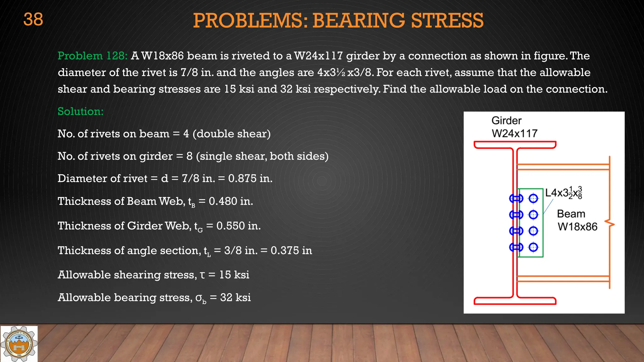
Problem128: A W18x86 beam is riveted to a W24x117 girder by a connection as shown in figure.The
diameter of the rivet is 7/8 in. and the angles are 4x3½x3/8. For each rivet, assume that the allowable
shear and bearing stresses are 15 ksi and 32 ksi respectively. Find the allowable load on the connection.
Solution:
No. of rivets on beam = 4 (double shear)
No. of rivets on girder = 8 (single shear, both sides)
Diameter of rivet = d = 7/8 in. = 0.875 in.
Thickness of Beam Web, tB = 0.480 in.
Thickness of Girder Web, tG = 0.550 in.
Thickness of angle section, tL = 3/8 in. = 0.375 in
Allowable shearing stress, τ = 15 ksi
Allowable bearing stress, σb = 32 ksi
38
39.
PROBLEMS: BEARING STRESS
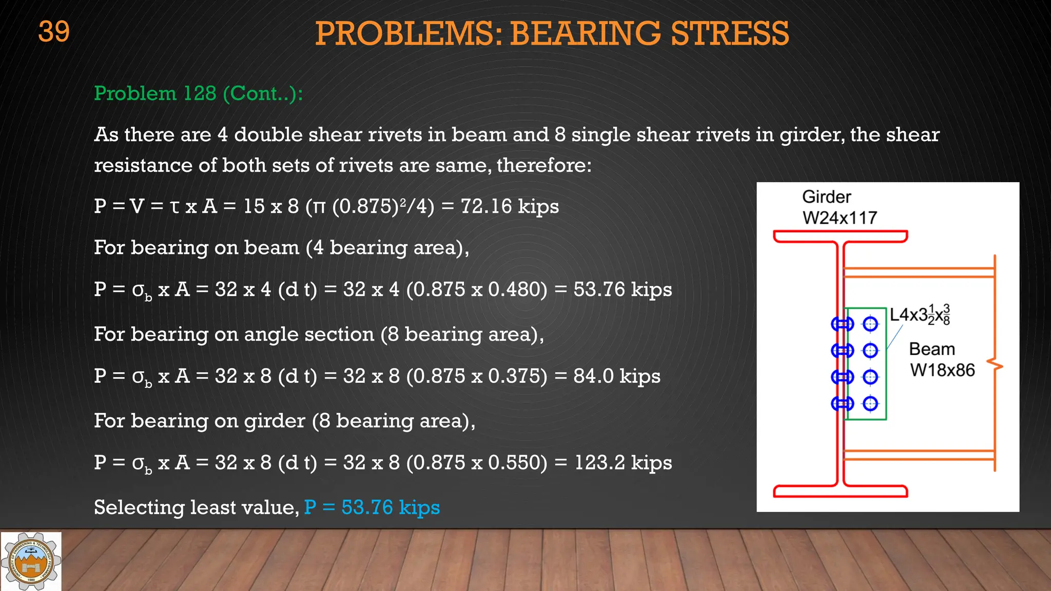
Problem128 (Cont..):
As there are 4 double shear rivets in beam and 8 single shear rivets in girder, the shear
resistance of both sets of rivets are same, therefore:
P = V = τ x A = 15 x 8 (π (0.875)2
/4) = 72.16 kips
For bearing on beam (4 bearing area),
P = σb x A = 32 x 4 (d t) = 32 x 4 (0.875 x 0.480) = 53.76 kips
For bearing on angle section (8 bearing area),
P = σb x A = 32 x 8 (d t) = 32 x 8 (0.875 x 0.375) = 84.0 kips
For bearing on girder (8 bearing area),
P = σb x A = 32 x 8 (d t) = 32 x 8 (0.875 x 0.550) = 123.2 kips
Selecting least value, P = 53.76 kips
39
40.
PROBLEMS: BEARING STRESS
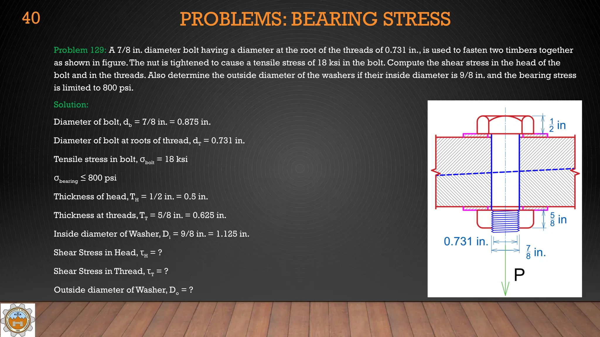
Problem129: A 7/8 in. diameter bolt having a diameter at the root of the threads of 0.731 in., is used to fasten two timbers together
as shown in figure.The nut is tightened to cause a tensile stress of 18 ksi in the bolt. Compute the shear stress in the head of the
bolt and in the threads. Also determine the outside diameter of the washers if their inside diameter is 9/8 in. and the bearing stress
is limited to 800 psi.
Solution:
Diameter of bolt, db = 7/8 in. = 0.875 in.
Diameter of bolt at roots of thread, dT = 0.731 in.
Tensile stress in bolt, σbolt = 18 ksi
σbearing ≤ 800 psi
Thickness of head,TH = 1/2 in. = 0.5 in.
Thickness at threads,TT = 5/8 in. = 0.625 in.
Inside diameter of Washer, Di = 9/8 in. = 1.125 in.
Shear Stress in Head, τH = ?
Shear Stress in Thread, τT = ?
Outside diameter of Washer, Do = ?
40
41.
PROBLEMS: BEARING STRESS
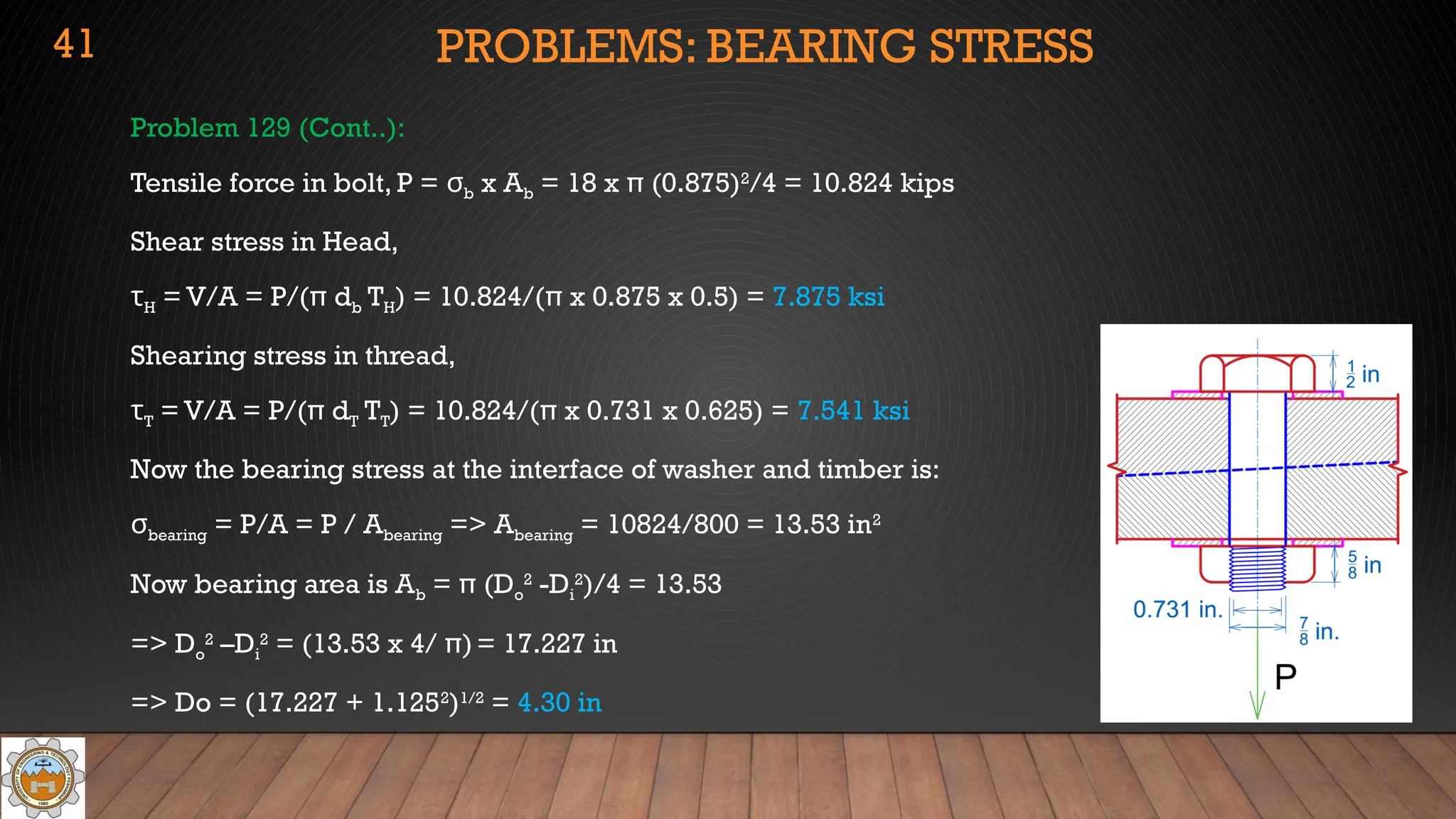
Problem129 (Cont..):
Tensile force in bolt, P = σb x Ab = 18 x π (0.875)2
/4 = 10.824 kips
Shear stress in Head,
τH = V/A = P/(π db TH) = 10.824/(π x 0.875 x 0.5) = 7.875 ksi
Shearing stress in thread,
τT = V/A = P/(π dT TT) = 10.824/(π x 0.731 x 0.625) = 7.541 ksi
Now the bearing stress at the interface of washer and timber is:
σbearing = P/A = P / Abearing => Abearing = 10824/800 = 13.53 in2
Now bearing area is Ab = π (Do
2
-Di
2
)/4 = 13.53
=> Do
2
–Di
2
= (13.53 x 4/ π)= 17.227 in
=> Do = (17.227 + 1.1252
)1/2
= 4.30 in
41
![PROBLEMS: SHEARING STRESS
Problem 121 : Referring to figure, compute the maximum force P that can apply by the machine operator if the
shearing stress in the pin at B and the axial stress in the control rod at C are limited to 4000 psi and 5000 psi
respectively.The diameters are 0.25 in for the pin and 0.50 in for the rod. Assume single shear for the pin at B.
Solution:
τpin ≤ 4000 psi, σrod ≤ 5000 psi
dpin =0.25 in, drod = 0.50 in.
Resolving Tension in rod into its rectangular components,
and applying equilibrium conditions:
M
Σ B = 0 => P x 6 –T sin(10) x 2 = 0 => T = 17.276 P (a)
F
Σ X = 0 => Tcos10 – BX = 0=> BX = 0.9848 T
M
Σ C = 0 => P x 8 – BY x 2 = 0 => BY = 4P
Shear force in pin is,V = (Bx
2
+ By
2
)1/2
= [(0.9848T)2
+ (4P)2
]1/2
(b)
32](https://image.slidesharecdn.com/module1courseintroductionsimplestress-250913164441-2da071ff/75/Module1-Course-Introduction-Simple-Stress-pptx-32-2048.jpg)
![PROBLEMS: SHEARING STRESS
Problem 121 (Cont..):
Putting value of T from equation (a) into equation (b)
V = [(0.9848T)2
+ (4P)2
]1/2
= [(17.013P)2
+ (4P)2
]1/2
= 17.477 P
Now limiting shear stress in pin, τ = V/A (single shear)
=> 4000 = 17.477 P/(π (0.25)2
/4)
=> P = 11.23 lb
Now limiting axial stress in rod, = T/A
σ
=> 5000 = 17.276P/ /(π (0.5)2
/4) from equation (a)
=> P = 56.83 lb
To limit both stress simultaneously, least value of P should be selected,
P = 11.23 lb
33](https://image.slidesharecdn.com/module1courseintroductionsimplestress-250913164441-2da071ff/75/Module1-Course-Introduction-Simple-Stress-pptx-33-2048.jpg)