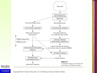
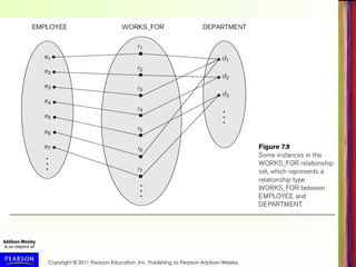
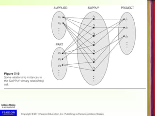
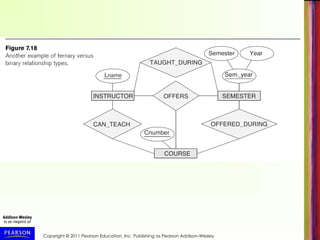
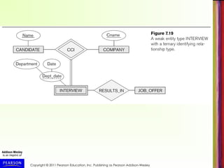
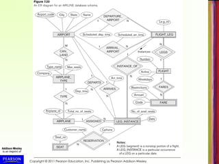
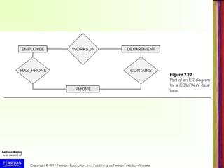
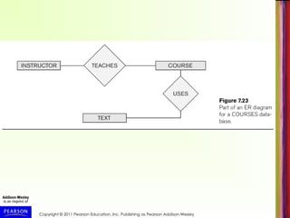
Copyright © 2011 Pearson Education, Inc. Publishing as Pearson Addison-Wesley
Chapter 7
Conceptual
Modeling and
Database Design
Copyright © 2011 Pearson Education, Inc. Publishing as Pearson Addison-Wesley
Chapter 7
Data Modeling Using
the Entity-
Relationship Model
Copyright © 2011 Pearson Education, Inc. Publishing as Pearson Addison-Wesley
Chapter Outline
• Overview of the Database Design Process
• Example Database Application (COMPANY)
• ER Model Concepts
– Entities and Attributes
– Entity Types, Value Sets, and Key Attributes
– Relationships and Relationship Types
– Weak Entity Types
– Roles and Attributes in Relationship Types
• ER Model Notations, Naming Conventions, Design Issues
• ER Diagram for COMPANY Schema
• Alternative Notations – UML class diagrams
• n-ary Relationships with degree n > 2
Copyright © 2011 Pearson Education, Inc. Publishing as Pearson Addison-Wesley
Overview of the Database Design
Process
• Two main activities (see Figure 7.1, next slide):
– Database schema design
– Application programs design
• Focus in this chapter on database schema design
– Given the database requirements, design the
conceptual schema for a database
• Application programs design focuses on the
programs and interfaces that access and update
the database (considered part of software
engineering discipline)
Copyright © 2011 Pearson Education, Inc. Publishing as Pearson Addison-Wesley
The Database Design Process
• Requirements Analysis and Specification is in the
realm of Systems Analysis and Design
– In this chapter, we assume it is already completed
– Briefly discussed in Chapter 10
• This and next chapter focus on Conceptual Design
(see Figure 7.1)
– Physical Design discussed in Chapter 20, after
presenting file structures and indexing (Chapters 17,
18)
– Logical Design presented in Chapter 9
Copyright © 2011 Pearson Education, Inc. Publishing as Pearson Addison-Wesley
The Entity-Relationship (ER) Model
• ER model is a conceptual data model for database design
– Has an associated notation (ER schema diagrams) for
drawing/displaying the database schema
– Many variations of ER model exists
– Also, many extensions (see EER model, Chapter 8)
• Next slide (Figure 7.2) shows a complete ER schema
diagram for a COMPANY database
– We will explain gradually how this design is created
– First we introduce the requirements for the COMPANY
database
– Then we present ER model concepts and diagrammatic
notation gradually, and design the schema step-by-step
Copyright © 2011 Pearson Education, Inc. Publishing as Pearson Addison-Wesley
Example: COMPANY Database
• Create a database schema design based on the
following (simplified) requirements for a
COMPANY Database:
– The company is organized into DEPARTMENTs.
Each department has a name, number and an
employee who manages the department. We keep
track of the start date of the department manager.
A department may have several locations.
– Each department controls a number of
PROJECTs. Each project has a unique name,
unique number and is located at a single location.
Copyright © 2011 Pearson Education, Inc. Publishing as Pearson Addison-Wesley
COMPANY Database (cont.)
– The database will store each EMPLOYEE’s name,
social security number (unique for each
employee), address, salary, sex, and birthdate.
• Each employee works for one department, but may
work on several projects.
• We keep track of the number of hours per week that
an employee currently works on each project.
• We also keep track of the direct supervisor of each
employee.
– An employee can have DEPENDENTs.
• For each dependent, the database keeps track of
their first name, sex, birthdate, and their relationship
to the employee (child, spouse, etc.).
Copyright © 2011 Pearson Education, Inc. Publishing as Pearson Addison-Wesley
ER Model Concepts
• Entities and Attributes
– Entities: Specific objects or things in the mini-world that are
represented in the database.
• Examples: the EMPLOYEE John Smith, the Research
DEPARTMENT, the ProductX PROJECT
– Attributes: Properties used to describe an entity.
• Examples: an EMPLOYEE entity may have the attributes
Name, SSN, Address, Sex, BirthDate
– Data values: A specific entity has a value for each of its
attributes.
• Example: An employee entity may have Name='John Smith',
SSN='123456789', Address ='731, Fondren, Houston, TX',
Sex='M', BirthDate='09-JAN-55‘
– Each attribute has a value set (or data type) associated
with it – e.g. integer, string, subrange, enumerated type, …
Copyright © 2011 Pearson Education, Inc. Publishing as Pearson Addison-Wesley
Types of Attributes
• Simple attribute (sometimes called atomic):
– Each entity has a single value for the attribute. For example, the
SSN or Sex of an employee.
– Not divisible
• Composite attribute (also called compound):
– The attribute may be composed of several components. For
example:
• Address(Apt#, House#, Street, City, State, ZipCode, Country), or
• Name(FirstName, MiddleName, LastName).
• Composition may form a hierarchy where some components are
themselves composite (Figure 7.4, next slide).
• Multi-valued attribute (also called repeating group or
collection):
– An single entity may have multiple values for that attribute. For
example, Color of a CAR or PreviousDegrees of a STUDENT.
• Denoted as {Color} or {PreviousDegrees}.
Copyright © 2011 Pearson Education, Inc. Publishing as Pearson Addison-Wesley
Types of Attributes (cont.)
• Composite and multi-valued attributes may be nested (to
any number of levels).
– Example: PreviousDegrees of a STUDENT can be a
composite multi-valued attribute denoted by
{PreviousDegrees (College, Year, Degree, Field)}
– Multiple PreviousDegrees values can exist for a
particular student
– Each has four subcomponent attributes:
• College, Year, Degree, Field
• Stored vs Derived attribute
• Age & Birth_date
Copyright © 2011 Pearson Education, Inc. Publishing as Pearson Addison-Wesley
Entity Types and Key Attributes
• Entities with the same basic attributes are
grouped (or typed) into an entity type.
– Examples: EMPLOYEE or PROJECT.
• Key attribute: an attribute of an entity type
for which each entity must have a unique
(distinct) value.
– Example: SSN of EMPLOYEE, or
PNUMBER of PROJECT, or PNAME of
PROJECT.
Copyright © 2011 Pearson Education, Inc. Publishing as Pearson Addison-Wesley
Entity Types and Key Attributes (cont.)
• A key attribute may be composite.
– Example: VehicleTagNumber (also known as
LicensePlateNo) of a CAR is a key with two
components (LicNumber, State).
• An entity type may have more than one key.
– The CAR entity type may have two keys:
• VehicleIdentificationNumber (popularly called VIN, unique
number stamped on each new car)
• VehicleTagNumber (Number, State)
• Each key is underlined in ER diagrams (see next
slides)
Copyright © 2011 Pearson Education, Inc. Publishing as Pearson Addison-Wesley
Displaying an Entity type
• In ER diagrams, the entity type name is
displayed in a rectangular box
• Attributes are displayed in ovals
– Each attribute is connected to its entity type
– Components of a composite attribute are
connected to the oval representing the
composite attribute
– Each key attribute is underlined
– Multivalued attributes displayed in double ovals
• See CAR example (Figure 7.7(a)) on next slide
Copyright © 2011 Pearson Education, Inc. Publishing as Pearson Addison-Wesley
Entity Set
• Each entity type will have a collection of individual
entities stored in the database
– Called the entity set
– Previous slide (Figure 7.7(b) show three CAR entities
in the entity set for CAR
– Same name (CAR) refers to both entity type and entity
set
– Object models (see Chapter 11) give different names to
the entity type and the entity set
– Entity set changes over time as entities are created
and deleted – represents current state of database
Copyright © 2011 Pearson Education, Inc. Publishing as Pearson Addison-Wesley
Initial Design of Entity Types for
the COMPANY Database Schema
• Based on the requirements, we can identify four initial
entity types in the COMPANY database:
– DEPARTMENT
– PROJECT
– EMPLOYEE
– DEPENDENT
• Initial design (Figure 7.8) on following slide, will be
refined into final design
• Initial attributes shown are derived from the
requirements description
Copyright © 2011 Pearson Education, Inc. Publishing as Pearson Addison-Wesley
Refining the initial design by introducing
Relationships
• The initial design is typically not complete
• Some aspects in the requirements will be
represented as relationships
• ER model has three main concepts:
– Entities (and their entity types and entity sets)
– Attributes (simple, composite, multivalued)
– Relationships (and their relationship types and
relationship sets)
• We introduce relationship concepts next
Copyright © 2011 Pearson Education, Inc. Publishing as Pearson Addison-Wesley
Relationships and Relationship Types
• A relationship relates two or more distinct entities, with a
specific meaning.
– For example, EMPLOYEE John Smith works on the ProductX
PROJECT, or EMPLOYEE Franklin Wong manages the
Research DEPARTMENT.
• Relationships of the same type are grouped or typed into
a relationship type.
– For example, the WORKS_ON relationship type in which
EMPLOYEEs and PROJECTs participate, or the MANAGES
relationship type in which EMPLOYEEs and DEPARTMENTs
participate.
• The degree of a relationship type is the number of
participating entity types.
– Both MANAGES and WORKS_ON are binary relationships.
Copyright © 2011 Pearson Education, Inc. Publishing as Pearson Addison-Wesley
Relationship Type vs. Relationship Set
• Relationship Type:
– Is the schema description of a relationship
– Identifies the relationship name and the
participating entity types
– Also identifies certain relationship constraints
• Relationship Set:
– The current set of relationship instances
represented in the database
– The current state of a relationship type
Copyright © 2011 Pearson Education, Inc. Publishing as Pearson Addison-Wesley
Relationship Set
• A set of associations (or relationship instances)
between individual entities from the participating
entity sets:
– Example: Figure 7.9 (next slide) shows a
relationship set for WORKS_FOR
– {r1, r2, r3, r4, r5, r6, r7, ...}
– Relationship instance r1=(e1, d1) means
EMPLOYEE e1 WORKS_FOR DEPARTMENT d1
– Associates e1 with d1
Copyright © 2011 Pearson Education, Inc. Publishing as Pearson Addison-Wesley
Relationship Type
• Previous figure displayed the relationship set
• Each instance in the set relates individual
participating entities – one from each participating
entity type
• In ER diagrams, we represent the relationship type
as follows:
– Diamond-shaped box is used to display a relationship
type
– Connected to the participating entity types via straight
lines
– Degree of a relationship type is the number of
participating entity types
Copyright © 2011 Pearson Education, Inc. Publishing as Pearson Addison-Wesley
Refining the COMPANY Initial Design by
Including Relationships
• By examining the requirements, attributes in the initial
design that refer to other entities are converted into
relationships (and removed from the entity types)
• Some of these relationship attributes (Figure 7.8,
repeated on next slide) are:
– The Department attribute of EMPLOYEE refers to the
DEPARTMENT entity that the employee WORKS_FOR
– The Manager attribute of DEPARTMENT refers to the
EMPLOYEE entity who MANAGES the DEPARTMENT
– The Supervisor attribute of EMPLOYEE refers to another
EMPLOYEE entity (this is called a recursive relationship)
– Several other similar attributes are converted into
relationships – can you identify those in next slide?
Copyright © 2011 Pearson Education, Inc. Publishing as Pearson Addison-Wesley
Refining the COMPANY Initial Design by
Including Relationships (cont.)
• Six relationship types are identified for the COMPANY
database schema (see Figure 7.2, repeated next slide)
• All are binary relationships (degree 2)
• Listed below with their participating entity types:
– WORKS_FOR (between EMPLOYEE, DEPARTMENT)
– MANAGES (also between EMPLOYEE, DEPARTMENT)
– CONTROLS (between DEPARTMENT, PROJECT)
– WORKS_ON (between EMPLOYEE, PROJECT)
– SUPERVISION (between EMPLOYEE (as subordinate),
EMPLOYEE (as supervisor))
– DEPENDENTS_OF (between EMPLOYEE, DEPENDENT)
Copyright © 2011 Pearson Education, Inc. Publishing as Pearson Addison-Wesley
Discussion on Relationship
Types
• In the refined design, some attributes from the initial entity
types are refined into relationships:
– Manager of DEPARTMENT -> MANAGES
– Works_on of EMPLOYEE -> WORKS_ON
– Department of EMPLOYEE -> WORKS_FOR
– etc
• In general, more than one relationship type can exist
between the same participating entity types
– MANAGES and WORKS_FOR are distinct relationship
types between EMPLOYEE and DEPARTMENT
– Different meanings and different relationship instances.
Copyright © 2011 Pearson Education, Inc. Publishing as Pearson Addison-Wesley
Recursive Relationship Type
• A relationship type with the same entity type participating
twice in two distinct roles
• Example: the SUPERVISION relationship
• EMPLOYEE participates twice in two distinct roles:
– supervisor (or boss) role
– supervisee (or subordinate) role
– must distinguish the roles in a relationship instance
• Each relationship instance ri relates two distinct
EMPLOYEE entities (see Figure 7.11, next slide):
– One employee in supervisor role (labeled 1 in Fig. 7.11)
– One employee in supervisee role (labeled 2 in Fig. 7.11)
Copyright © 2011 Pearson Education, Inc. Publishing as Pearson Addison-Wesley
Weak Entity Types
• An entity type that does not have a key attribute on its own
• A weak entity must participate in an identifying relationship type with
an owner (or identifying) entity type
• Individual entities are identified by the combination of:
– A partial key of the weak entity type
– The particular entity they are related to in the identifying entity
type
• Example (see Figure 7.2):
– A DEPENDENT entity is identified by the dependent’s first name,
and the specific EMPLOYEE with whom the dependent is related
– Name of DEPENDENT is the partial key
– DEPENDENT is a weak entity type
– EMPLOYEE is its identifying (owner) entity type via the identifying
relationship type DEPENDENT_OF
Copyright © 2011 Pearson Education, Inc. Publishing as Pearson Addison-Wesley
Constraints on Relationships
• Constraints on Relationship Types
– Two main types of constraints on binary relationships
– Cardinality Ratio (specifies maximum participation)
• One-to-one (1:1)
• One-to-many (1:N) or Many-to-one (N:1)
• Many-to-many (M:N)
– Existence Dependency Constraint (specifies minimum
participation) (also called participation constraint)
• zero (optional participation, not existence-dependent)
• one or more (mandatory participation, existence-dependent)
Copyright © 2011 Pearson Education, Inc. Publishing as Pearson Addison-Wesley
Constraints on Relationships (cont.)
• Cardinality ratio specified by labeling 1, M, or N to
relationship lines in ER diagrams.
• See Figure 7.2, repeated in next slide
• Total participation specified by double line, partial
participation by single line.
• These constraints are derived from the real-world
meaning and characteristics of each relationship type
• In some ER diagrammatic notation, it is common to
specify cardinality ration and participation constraint jointly
using (min, max) notation
– Called (min, max) constraints or multiplicities
Copyright © 2011 Pearson Education, Inc. Publishing as Pearson Addison-Wesley
Displaying a Recursive
Relationship Type in ER Diagrams
• In a recursive relationship type.
– Both participations are same entity type in
different roles.
– For example, SUPERVISION relationships
between EMPLOYEE (in role of supervisor or
boss) and (another) EMPLOYEE (in role of
subordinate or worker).
• In ER diagram, need to display role names to
distinguish participations (see Figure 7.2).
• Role names can also be optionally displayed for
other relationship types
Copyright © 2011 Pearson Education, Inc. Publishing as Pearson Addison-Wesley
Attributes of Relationship Types
• A relationship type can have attributes:
– For example, HoursPerWeek of WORKS_ON
– Its value for each relationship instance
describes the number of hours per week that
an EMPLOYEE works on a PROJECT.
• A value of HoursPerWeek depends on a particular
(employee, project) combination
– Most relationship attributes are used with M:N
relationships
• In 1:N relationships, they can be transferred to the
entity type on the N-side of the relationship
Copyright © 2011 Pearson Education, Inc. Publishing as Pearson Addison-Wesley
Alternative (min, max) notation
• Alternative way to specify relationship constraints; pecified on each
participation of an entity type E in a relationship type R
• Specifies that each entity e in E participates in at least min and at
most max relationship instances in R
• Default (no constraint): min=0, max=n (signifying no limits)
• Must have minmax, min0, max 1
• Derived from the knowledge of mini-world constraints
• Examples:
– A department has exactly one manager and an employee can
manage at most one department.
• Specify (0,1) for participation of EMPLOYEE in MANAGES
• Specify (1,1) for participation of DEPARTMENT in MANAGES
– An employee can work for exactly one department but a
department can have any number of employees.
• Specify (1,1) for participation of EMPLOYEE in WORKS_FOR
• Specify (0,n) for participation of DEPARTMENT in WORKS_FOR
Copyright © 2011 Pearson Education, Inc. Publishing as Pearson Addison-Wesley
Alternative (min, max) notation (cont.)
• Figure 7.15 (next slide) shows the complete COMPANY
ER schema diagram with the (min, max) notation
• Also shows all the (optional) role names
• Important: In some popular diagrammatic notations, the
placement of (min, max) are reversed (placed on the other
side of the binary relationship) – for example, in UML
class diagrams (see later in this chapter)
Copyright © 2011 Pearson Education, Inc. Publishing as Pearson Addison-Wesley
Summary of ER Diagrams
• Next two slides (Figure 7.14) summarizes
the ER Diagrammatic notations described
so far
Copyright © 2011 Pearson Education, Inc. Publishing as Pearson Addison-Wesley
Continued next page…
Copyright © 2011 Pearson Education, Inc. Publishing as Pearson Addison-Wesley
Alternative diagrammatic notation
• ER diagrams (as described here) is one popular
method for displaying database schemas
• Many other diagrammatic notations exist in the
literature and in various database design and
modeling tools
• Appendix A illustrates some of the alternative
notations that have been used
• UML class diagrams is representative of an
alternative way of displaying ER concepts that is
used in several automated design tools
Copyright © 2011 Pearson Education, Inc. Publishing as Pearson Addison-Wesley
UML Class Diagrams
• UML (Universal Modeling Language) is a popular
language/methodology for object-oriented software design
• Part of software design is specifying classes using class
diagrams – this is somewhat similar to ER design
• Classes (similar to entity types) as displayed as large
rounded boxes with three sections:
– Top section includes entity type (class) name
– Second section includes attributes
– Third section includes class operations (operations are not
in basic ER model)
• Relationships (called associations) represented as lines
connecting the classes
– Other UML terminology also differs from ER terminology
• UML has many other types of diagrams for software
design (see Chapter 10)
Copyright © 2011 Pearson Education, Inc. Publishing as Pearson Addison-Wesley
UML Class Diagrams (cont.)
• Next slide (Figure 7.16) shows example of UML class
diagrams for the COMPANY database schema
• Multiplicities (similar to (min, max) constraints) placed on
opposite end when compared to our previous notation:
– Displayed as min..max
– * represents no maximum limit on participation (like N)
• Two kinds of relationships
– Association: Relationship between two independent
objects; displayed as lines
– Aggregation: Relationship between object and its parts;
displayed as lines with small diamond at object end
• Weak entity can be represented using concept of
qualified association/aggregation (discriminator
similar to partial key)
• Relationship names are optional; relationship instances
called links; relationship attributes called link attributes
Copyright © 2011 Pearson Education, Inc. Publishing as Pearson Addison-Wesley
Relationships of Higher Degree
• Recall that degree of a relationship type is the
number of participating entities in each instance
• Relationship types of degree 2 are called binary,
degree 3 are ternary, and degree n are n-ary
• Example: A relationship instance in SUPPLY (Figure 7.10 ,
next slide) relates three entities (s, p, j) where s is a
SUPPLIER, p a PART, j a PROJECT such that s currently
supplies part p to project j (with Quantity items per month)
• In general, an n-ary relationship (where n > 2) is not
equivalent to n binary relationships
• Constraints are harder to specify for higher-degree
relationships (n > 2) than for binary relationships
Copyright © 2011 Pearson Education, Inc. Publishing as Pearson Addison-Wesley
Discussion of n-ary relationships
• In general, 3 binary relationships can represent different
information than a single ternary relationship (see Figure
7.17a and b on next slide)
• If needed, the binary and n-ary relationships can all be
included in the schema design
• In some cases, a ternary relationship can be represented
as a weak entity type if the data model allows multiple
identifying relationships (and hence multiple owner entity
types) (see Figure 7.17c)
Copyright © 2011 Pearson Education, Inc. Publishing as Pearson Addison-Wesley
Discussion of n-ary relationships (cont.)
• If a particular binary relationship can be derived
from a higher-degree relationship at all times,
then it is redundant
• For example, TAUGHT_DURING binary
relationship in Figure 7.18 (see next slide) can be
derived from the ternary relationship OFFERS
(based on the meaning of the relationships)
• It all depends on the meaning of the relationships
in the real world
Copyright © 2011 Pearson Education, Inc. Publishing as Pearson Addison-Wesley
Displaying constraints on higher-degree
relationships
• The (min, max) constraints can be displayed on the edges
– however, they do not fully describe the constraints
• Displaying a 1, M, or N indicates additional constraints
– An M or N indicates no constraint
– A 1 indicates that an entity can participate in at most one
relationship instance that has a particular combination of the
other participating entities
• In general, both (min, max) and 1, M, or N are needed to
describe fully the constraints
Copyright © 2011 Pearson Education, Inc. Publishing as Pearson Addison-Wesley
Extended Entity-Relationship
(EER) Model (in next chapter)
• The basic ER model described so far does not
support specialization and generalization
abstractions
• Next chapter illustrates how the ER model can be
extended with
– Type-subtype and set-subset relationships
– Specialization/Generalization Hierarchies
– Notation to display them in EER diagrams
Copyright © 2011 Pearson Education, Inc. Publishing as Pearson Addison-Wesley
Chapter 7 Summary
• ER Model Concepts: Entities, attributes,
relationships
• Constraints in the ER model
• Using ER in step-by-step conceptual schema
design for the COMPANY database
• ER Diagrams - Notation
• Alternative Notations – UML class diagrams,
others
Copyright © 2011 Pearson Education, Inc. Publishing as Pearson Addison-Wesley
Additional Examples
• Next few slides are additional figures from the
chapter, and figures from the Chapter 7 exercises
Copyright © 2011 Pearson Education, Inc. Publishing as Pearson Addison-Wesley

Modern Database Management: Principles, Practices, and Applications

  • 1.
    Copyright © 2011Pearson Education, Inc. Publishing as Pearson Addison-Wesley Chapter 7 Conceptual Modeling and Database Design
  • 2.
    Copyright © 2011Pearson Education, Inc. Publishing as Pearson Addison-Wesley Chapter 7 Data Modeling Using the Entity- Relationship Model
  • 3.
    Copyright © 2011Pearson Education, Inc. Publishing as Pearson Addison-Wesley Chapter Outline • Overview of the Database Design Process • Example Database Application (COMPANY) • ER Model Concepts – Entities and Attributes – Entity Types, Value Sets, and Key Attributes – Relationships and Relationship Types – Weak Entity Types – Roles and Attributes in Relationship Types • ER Model Notations, Naming Conventions, Design Issues • ER Diagram for COMPANY Schema • Alternative Notations – UML class diagrams • n-ary Relationships with degree n > 2
  • 4.
    Copyright © 2011Pearson Education, Inc. Publishing as Pearson Addison-Wesley Overview of the Database Design Process • Two main activities (see Figure 7.1, next slide): – Database schema design – Application programs design • Focus in this chapter on database schema design – Given the database requirements, design the conceptual schema for a database • Application programs design focuses on the programs and interfaces that access and update the database (considered part of software engineering discipline)
  • 5.
    Copyright © 2011Pearson Education, Inc. Publishing as Pearson Addison-Wesley
  • 6.
    Copyright © 2011Pearson Education, Inc. Publishing as Pearson Addison-Wesley The Database Design Process • Requirements Analysis and Specification is in the realm of Systems Analysis and Design – In this chapter, we assume it is already completed – Briefly discussed in Chapter 10 • This and next chapter focus on Conceptual Design (see Figure 7.1) – Physical Design discussed in Chapter 20, after presenting file structures and indexing (Chapters 17, 18) – Logical Design presented in Chapter 9
  • 7.
    Copyright © 2011Pearson Education, Inc. Publishing as Pearson Addison-Wesley The Entity-Relationship (ER) Model • ER model is a conceptual data model for database design – Has an associated notation (ER schema diagrams) for drawing/displaying the database schema – Many variations of ER model exists – Also, many extensions (see EER model, Chapter 8) • Next slide (Figure 7.2) shows a complete ER schema diagram for a COMPANY database – We will explain gradually how this design is created – First we introduce the requirements for the COMPANY database – Then we present ER model concepts and diagrammatic notation gradually, and design the schema step-by-step
  • 8.
    Copyright © 2011Pearson Education, Inc. Publishing as Pearson Addison-Wesley
  • 9.
    Copyright © 2011Pearson Education, Inc. Publishing as Pearson Addison-Wesley Example: COMPANY Database • Create a database schema design based on the following (simplified) requirements for a COMPANY Database: – The company is organized into DEPARTMENTs. Each department has a name, number and an employee who manages the department. We keep track of the start date of the department manager. A department may have several locations. – Each department controls a number of PROJECTs. Each project has a unique name, unique number and is located at a single location.
  • 10.
    Copyright © 2011Pearson Education, Inc. Publishing as Pearson Addison-Wesley COMPANY Database (cont.) – The database will store each EMPLOYEE’s name, social security number (unique for each employee), address, salary, sex, and birthdate. • Each employee works for one department, but may work on several projects. • We keep track of the number of hours per week that an employee currently works on each project. • We also keep track of the direct supervisor of each employee. – An employee can have DEPENDENTs. • For each dependent, the database keeps track of their first name, sex, birthdate, and their relationship to the employee (child, spouse, etc.).
  • 11.
    Copyright © 2011Pearson Education, Inc. Publishing as Pearson Addison-Wesley ER Model Concepts • Entities and Attributes – Entities: Specific objects or things in the mini-world that are represented in the database. • Examples: the EMPLOYEE John Smith, the Research DEPARTMENT, the ProductX PROJECT – Attributes: Properties used to describe an entity. • Examples: an EMPLOYEE entity may have the attributes Name, SSN, Address, Sex, BirthDate – Data values: A specific entity has a value for each of its attributes. • Example: An employee entity may have Name='John Smith', SSN='123456789', Address ='731, Fondren, Houston, TX', Sex='M', BirthDate='09-JAN-55‘ – Each attribute has a value set (or data type) associated with it – e.g. integer, string, subrange, enumerated type, …
  • 12.
    Copyright © 2011Pearson Education, Inc. Publishing as Pearson Addison-Wesley Types of Attributes • Simple attribute (sometimes called atomic): – Each entity has a single value for the attribute. For example, the SSN or Sex of an employee. – Not divisible • Composite attribute (also called compound): – The attribute may be composed of several components. For example: • Address(Apt#, House#, Street, City, State, ZipCode, Country), or • Name(FirstName, MiddleName, LastName). • Composition may form a hierarchy where some components are themselves composite (Figure 7.4, next slide). • Multi-valued attribute (also called repeating group or collection): – An single entity may have multiple values for that attribute. For example, Color of a CAR or PreviousDegrees of a STUDENT. • Denoted as {Color} or {PreviousDegrees}.
  • 13.
    Copyright © 2011Pearson Education, Inc. Publishing as Pearson Addison-Wesley
  • 14.
    Copyright © 2011Pearson Education, Inc. Publishing as Pearson Addison-Wesley Types of Attributes (cont.) • Composite and multi-valued attributes may be nested (to any number of levels). – Example: PreviousDegrees of a STUDENT can be a composite multi-valued attribute denoted by {PreviousDegrees (College, Year, Degree, Field)} – Multiple PreviousDegrees values can exist for a particular student – Each has four subcomponent attributes: • College, Year, Degree, Field • Stored vs Derived attribute • Age & Birth_date
  • 15.
    Copyright © 2011Pearson Education, Inc. Publishing as Pearson Addison-Wesley Entity Types and Key Attributes • Entities with the same basic attributes are grouped (or typed) into an entity type. – Examples: EMPLOYEE or PROJECT. • Key attribute: an attribute of an entity type for which each entity must have a unique (distinct) value. – Example: SSN of EMPLOYEE, or PNUMBER of PROJECT, or PNAME of PROJECT.
  • 16.
    Copyright © 2011Pearson Education, Inc. Publishing as Pearson Addison-Wesley Entity Types and Key Attributes (cont.) • A key attribute may be composite. – Example: VehicleTagNumber (also known as LicensePlateNo) of a CAR is a key with two components (LicNumber, State). • An entity type may have more than one key. – The CAR entity type may have two keys: • VehicleIdentificationNumber (popularly called VIN, unique number stamped on each new car) • VehicleTagNumber (Number, State) • Each key is underlined in ER diagrams (see next slides)
  • 17.
    Copyright © 2011Pearson Education, Inc. Publishing as Pearson Addison-Wesley Displaying an Entity type • In ER diagrams, the entity type name is displayed in a rectangular box • Attributes are displayed in ovals – Each attribute is connected to its entity type – Components of a composite attribute are connected to the oval representing the composite attribute – Each key attribute is underlined – Multivalued attributes displayed in double ovals • See CAR example (Figure 7.7(a)) on next slide
  • 18.
    Copyright © 2011Pearson Education, Inc. Publishing as Pearson Addison-Wesley
  • 19.
    Copyright © 2011Pearson Education, Inc. Publishing as Pearson Addison-Wesley Entity Set • Each entity type will have a collection of individual entities stored in the database – Called the entity set – Previous slide (Figure 7.7(b) show three CAR entities in the entity set for CAR – Same name (CAR) refers to both entity type and entity set – Object models (see Chapter 11) give different names to the entity type and the entity set – Entity set changes over time as entities are created and deleted – represents current state of database
  • 20.
    Copyright © 2011Pearson Education, Inc. Publishing as Pearson Addison-Wesley Initial Design of Entity Types for the COMPANY Database Schema • Based on the requirements, we can identify four initial entity types in the COMPANY database: – DEPARTMENT – PROJECT – EMPLOYEE – DEPENDENT • Initial design (Figure 7.8) on following slide, will be refined into final design • Initial attributes shown are derived from the requirements description
  • 21.
    Copyright © 2011Pearson Education, Inc. Publishing as Pearson Addison-Wesley
  • 22.
    Copyright © 2011Pearson Education, Inc. Publishing as Pearson Addison-Wesley Refining the initial design by introducing Relationships • The initial design is typically not complete • Some aspects in the requirements will be represented as relationships • ER model has three main concepts: – Entities (and their entity types and entity sets) – Attributes (simple, composite, multivalued) – Relationships (and their relationship types and relationship sets) • We introduce relationship concepts next
  • 23.
    Copyright © 2011Pearson Education, Inc. Publishing as Pearson Addison-Wesley Relationships and Relationship Types • A relationship relates two or more distinct entities, with a specific meaning. – For example, EMPLOYEE John Smith works on the ProductX PROJECT, or EMPLOYEE Franklin Wong manages the Research DEPARTMENT. • Relationships of the same type are grouped or typed into a relationship type. – For example, the WORKS_ON relationship type in which EMPLOYEEs and PROJECTs participate, or the MANAGES relationship type in which EMPLOYEEs and DEPARTMENTs participate. • The degree of a relationship type is the number of participating entity types. – Both MANAGES and WORKS_ON are binary relationships.
  • 24.
    Copyright © 2011Pearson Education, Inc. Publishing as Pearson Addison-Wesley Relationship Type vs. Relationship Set • Relationship Type: – Is the schema description of a relationship – Identifies the relationship name and the participating entity types – Also identifies certain relationship constraints • Relationship Set: – The current set of relationship instances represented in the database – The current state of a relationship type
  • 25.
    Copyright © 2011Pearson Education, Inc. Publishing as Pearson Addison-Wesley Relationship Set • A set of associations (or relationship instances) between individual entities from the participating entity sets: – Example: Figure 7.9 (next slide) shows a relationship set for WORKS_FOR – {r1, r2, r3, r4, r5, r6, r7, ...} – Relationship instance r1=(e1, d1) means EMPLOYEE e1 WORKS_FOR DEPARTMENT d1 – Associates e1 with d1
  • 26.
    Copyright © 2011Pearson Education, Inc. Publishing as Pearson Addison-Wesley
  • 27.
    Copyright © 2011Pearson Education, Inc. Publishing as Pearson Addison-Wesley Relationship Type • Previous figure displayed the relationship set • Each instance in the set relates individual participating entities – one from each participating entity type • In ER diagrams, we represent the relationship type as follows: – Diamond-shaped box is used to display a relationship type – Connected to the participating entity types via straight lines – Degree of a relationship type is the number of participating entity types
  • 28.
    Copyright © 2011Pearson Education, Inc. Publishing as Pearson Addison-Wesley Refining the COMPANY Initial Design by Including Relationships • By examining the requirements, attributes in the initial design that refer to other entities are converted into relationships (and removed from the entity types) • Some of these relationship attributes (Figure 7.8, repeated on next slide) are: – The Department attribute of EMPLOYEE refers to the DEPARTMENT entity that the employee WORKS_FOR – The Manager attribute of DEPARTMENT refers to the EMPLOYEE entity who MANAGES the DEPARTMENT – The Supervisor attribute of EMPLOYEE refers to another EMPLOYEE entity (this is called a recursive relationship) – Several other similar attributes are converted into relationships – can you identify those in next slide?
  • 29.
    Copyright © 2011Pearson Education, Inc. Publishing as Pearson Addison-Wesley
  • 30.
    Copyright © 2011Pearson Education, Inc. Publishing as Pearson Addison-Wesley Refining the COMPANY Initial Design by Including Relationships (cont.) • Six relationship types are identified for the COMPANY database schema (see Figure 7.2, repeated next slide) • All are binary relationships (degree 2) • Listed below with their participating entity types: – WORKS_FOR (between EMPLOYEE, DEPARTMENT) – MANAGES (also between EMPLOYEE, DEPARTMENT) – CONTROLS (between DEPARTMENT, PROJECT) – WORKS_ON (between EMPLOYEE, PROJECT) – SUPERVISION (between EMPLOYEE (as subordinate), EMPLOYEE (as supervisor)) – DEPENDENTS_OF (between EMPLOYEE, DEPENDENT)
  • 31.
    Copyright © 2011Pearson Education, Inc. Publishing as Pearson Addison-Wesley
  • 32.
    Copyright © 2011Pearson Education, Inc. Publishing as Pearson Addison-Wesley Discussion on Relationship Types • In the refined design, some attributes from the initial entity types are refined into relationships: – Manager of DEPARTMENT -> MANAGES – Works_on of EMPLOYEE -> WORKS_ON – Department of EMPLOYEE -> WORKS_FOR – etc • In general, more than one relationship type can exist between the same participating entity types – MANAGES and WORKS_FOR are distinct relationship types between EMPLOYEE and DEPARTMENT – Different meanings and different relationship instances.
  • 33.
    Copyright © 2011Pearson Education, Inc. Publishing as Pearson Addison-Wesley Recursive Relationship Type • A relationship type with the same entity type participating twice in two distinct roles • Example: the SUPERVISION relationship • EMPLOYEE participates twice in two distinct roles: – supervisor (or boss) role – supervisee (or subordinate) role – must distinguish the roles in a relationship instance • Each relationship instance ri relates two distinct EMPLOYEE entities (see Figure 7.11, next slide): – One employee in supervisor role (labeled 1 in Fig. 7.11) – One employee in supervisee role (labeled 2 in Fig. 7.11)
  • 34.
    Copyright © 2011Pearson Education, Inc. Publishing as Pearson Addison-Wesley
  • 35.
    Copyright © 2011Pearson Education, Inc. Publishing as Pearson Addison-Wesley Weak Entity Types • An entity type that does not have a key attribute on its own • A weak entity must participate in an identifying relationship type with an owner (or identifying) entity type • Individual entities are identified by the combination of: – A partial key of the weak entity type – The particular entity they are related to in the identifying entity type • Example (see Figure 7.2): – A DEPENDENT entity is identified by the dependent’s first name, and the specific EMPLOYEE with whom the dependent is related – Name of DEPENDENT is the partial key – DEPENDENT is a weak entity type – EMPLOYEE is its identifying (owner) entity type via the identifying relationship type DEPENDENT_OF
  • 36.
    Copyright © 2011Pearson Education, Inc. Publishing as Pearson Addison-Wesley Constraints on Relationships • Constraints on Relationship Types – Two main types of constraints on binary relationships – Cardinality Ratio (specifies maximum participation) • One-to-one (1:1) • One-to-many (1:N) or Many-to-one (N:1) • Many-to-many (M:N) – Existence Dependency Constraint (specifies minimum participation) (also called participation constraint) • zero (optional participation, not existence-dependent) • one or more (mandatory participation, existence-dependent)
  • 37.
    Copyright © 2011Pearson Education, Inc. Publishing as Pearson Addison-Wesley Constraints on Relationships (cont.) • Cardinality ratio specified by labeling 1, M, or N to relationship lines in ER diagrams. • See Figure 7.2, repeated in next slide • Total participation specified by double line, partial participation by single line. • These constraints are derived from the real-world meaning and characteristics of each relationship type • In some ER diagrammatic notation, it is common to specify cardinality ration and participation constraint jointly using (min, max) notation – Called (min, max) constraints or multiplicities
  • 38.
    Copyright © 2011Pearson Education, Inc. Publishing as Pearson Addison-Wesley
  • 39.
    Copyright © 2011Pearson Education, Inc. Publishing as Pearson Addison-Wesley Displaying a Recursive Relationship Type in ER Diagrams • In a recursive relationship type. – Both participations are same entity type in different roles. – For example, SUPERVISION relationships between EMPLOYEE (in role of supervisor or boss) and (another) EMPLOYEE (in role of subordinate or worker). • In ER diagram, need to display role names to distinguish participations (see Figure 7.2). • Role names can also be optionally displayed for other relationship types
  • 40.
    Copyright © 2011Pearson Education, Inc. Publishing as Pearson Addison-Wesley Attributes of Relationship Types • A relationship type can have attributes: – For example, HoursPerWeek of WORKS_ON – Its value for each relationship instance describes the number of hours per week that an EMPLOYEE works on a PROJECT. • A value of HoursPerWeek depends on a particular (employee, project) combination – Most relationship attributes are used with M:N relationships • In 1:N relationships, they can be transferred to the entity type on the N-side of the relationship
  • 41.
    Copyright © 2011Pearson Education, Inc. Publishing as Pearson Addison-Wesley Alternative (min, max) notation • Alternative way to specify relationship constraints; pecified on each participation of an entity type E in a relationship type R • Specifies that each entity e in E participates in at least min and at most max relationship instances in R • Default (no constraint): min=0, max=n (signifying no limits) • Must have minmax, min0, max 1 • Derived from the knowledge of mini-world constraints • Examples: – A department has exactly one manager and an employee can manage at most one department. • Specify (0,1) for participation of EMPLOYEE in MANAGES • Specify (1,1) for participation of DEPARTMENT in MANAGES – An employee can work for exactly one department but a department can have any number of employees. • Specify (1,1) for participation of EMPLOYEE in WORKS_FOR • Specify (0,n) for participation of DEPARTMENT in WORKS_FOR
  • 42.
    Copyright © 2011Pearson Education, Inc. Publishing as Pearson Addison-Wesley Alternative (min, max) notation (cont.) • Figure 7.15 (next slide) shows the complete COMPANY ER schema diagram with the (min, max) notation • Also shows all the (optional) role names • Important: In some popular diagrammatic notations, the placement of (min, max) are reversed (placed on the other side of the binary relationship) – for example, in UML class diagrams (see later in this chapter)
  • 43.
    Copyright © 2011Pearson Education, Inc. Publishing as Pearson Addison-Wesley
  • 44.
    Copyright © 2011Pearson Education, Inc. Publishing as Pearson Addison-Wesley Summary of ER Diagrams • Next two slides (Figure 7.14) summarizes the ER Diagrammatic notations described so far
  • 45.
    Copyright © 2011Pearson Education, Inc. Publishing as Pearson Addison-Wesley Continued next page…
  • 46.
    Copyright © 2011Pearson Education, Inc. Publishing as Pearson Addison-Wesley
  • 47.
    Copyright © 2011Pearson Education, Inc. Publishing as Pearson Addison-Wesley Alternative diagrammatic notation • ER diagrams (as described here) is one popular method for displaying database schemas • Many other diagrammatic notations exist in the literature and in various database design and modeling tools • Appendix A illustrates some of the alternative notations that have been used • UML class diagrams is representative of an alternative way of displaying ER concepts that is used in several automated design tools
  • 48.
    Copyright © 2011Pearson Education, Inc. Publishing as Pearson Addison-Wesley UML Class Diagrams • UML (Universal Modeling Language) is a popular language/methodology for object-oriented software design • Part of software design is specifying classes using class diagrams – this is somewhat similar to ER design • Classes (similar to entity types) as displayed as large rounded boxes with three sections: – Top section includes entity type (class) name – Second section includes attributes – Third section includes class operations (operations are not in basic ER model) • Relationships (called associations) represented as lines connecting the classes – Other UML terminology also differs from ER terminology • UML has many other types of diagrams for software design (see Chapter 10)
  • 49.
    Copyright © 2011Pearson Education, Inc. Publishing as Pearson Addison-Wesley UML Class Diagrams (cont.) • Next slide (Figure 7.16) shows example of UML class diagrams for the COMPANY database schema • Multiplicities (similar to (min, max) constraints) placed on opposite end when compared to our previous notation: – Displayed as min..max – * represents no maximum limit on participation (like N) • Two kinds of relationships – Association: Relationship between two independent objects; displayed as lines – Aggregation: Relationship between object and its parts; displayed as lines with small diamond at object end • Weak entity can be represented using concept of qualified association/aggregation (discriminator similar to partial key) • Relationship names are optional; relationship instances called links; relationship attributes called link attributes
  • 50.
    Copyright © 2011Pearson Education, Inc. Publishing as Pearson Addison-Wesley
  • 51.
    Copyright © 2011Pearson Education, Inc. Publishing as Pearson Addison-Wesley Relationships of Higher Degree • Recall that degree of a relationship type is the number of participating entities in each instance • Relationship types of degree 2 are called binary, degree 3 are ternary, and degree n are n-ary • Example: A relationship instance in SUPPLY (Figure 7.10 , next slide) relates three entities (s, p, j) where s is a SUPPLIER, p a PART, j a PROJECT such that s currently supplies part p to project j (with Quantity items per month) • In general, an n-ary relationship (where n > 2) is not equivalent to n binary relationships • Constraints are harder to specify for higher-degree relationships (n > 2) than for binary relationships
  • 52.
    Copyright © 2011Pearson Education, Inc. Publishing as Pearson Addison-Wesley
  • 53.
    Copyright © 2011Pearson Education, Inc. Publishing as Pearson Addison-Wesley Discussion of n-ary relationships • In general, 3 binary relationships can represent different information than a single ternary relationship (see Figure 7.17a and b on next slide) • If needed, the binary and n-ary relationships can all be included in the schema design • In some cases, a ternary relationship can be represented as a weak entity type if the data model allows multiple identifying relationships (and hence multiple owner entity types) (see Figure 7.17c)
  • 54.
    Copyright © 2011Pearson Education, Inc. Publishing as Pearson Addison-Wesley
  • 55.
    Copyright © 2011Pearson Education, Inc. Publishing as Pearson Addison-Wesley Discussion of n-ary relationships (cont.) • If a particular binary relationship can be derived from a higher-degree relationship at all times, then it is redundant • For example, TAUGHT_DURING binary relationship in Figure 7.18 (see next slide) can be derived from the ternary relationship OFFERS (based on the meaning of the relationships) • It all depends on the meaning of the relationships in the real world
  • 56.
    Copyright © 2011Pearson Education, Inc. Publishing as Pearson Addison-Wesley
  • 57.
    Copyright © 2011Pearson Education, Inc. Publishing as Pearson Addison-Wesley Displaying constraints on higher-degree relationships • The (min, max) constraints can be displayed on the edges – however, they do not fully describe the constraints • Displaying a 1, M, or N indicates additional constraints – An M or N indicates no constraint – A 1 indicates that an entity can participate in at most one relationship instance that has a particular combination of the other participating entities • In general, both (min, max) and 1, M, or N are needed to describe fully the constraints
  • 58.
    Copyright © 2011Pearson Education, Inc. Publishing as Pearson Addison-Wesley Extended Entity-Relationship (EER) Model (in next chapter) • The basic ER model described so far does not support specialization and generalization abstractions • Next chapter illustrates how the ER model can be extended with – Type-subtype and set-subset relationships – Specialization/Generalization Hierarchies – Notation to display them in EER diagrams
  • 59.
    Copyright © 2011Pearson Education, Inc. Publishing as Pearson Addison-Wesley Chapter 7 Summary • ER Model Concepts: Entities, attributes, relationships • Constraints in the ER model • Using ER in step-by-step conceptual schema design for the COMPANY database • ER Diagrams - Notation • Alternative Notations – UML class diagrams, others
  • 60.
    Copyright © 2011Pearson Education, Inc. Publishing as Pearson Addison-Wesley Additional Examples • Next few slides are additional figures from the chapter, and figures from the Chapter 7 exercises
  • 61.
    Copyright © 2011Pearson Education, Inc. Publishing as Pearson Addison-Wesley
  • 62.
    Copyright © 2011Pearson Education, Inc. Publishing as Pearson Addison-Wesley
  • 63.
    Copyright © 2011Pearson Education, Inc. Publishing as Pearson Addison-Wesley
  • 64.
    Copyright © 2011Pearson Education, Inc. Publishing as Pearson Addison-Wesley
  • 65.
    Copyright © 2011Pearson Education, Inc. Publishing as Pearson Addison-Wesley
  • 66.
    Copyright © 2011Pearson Education, Inc. Publishing as Pearson Addison-Wesley