1. 3/23/2010
1
Lecture 5
Multipath Fading Channels
Mobile Communication Systems
Dr Charan Litchfield C.litchfield@gre.ac.uk
22nd October 2008
Resources:
Mobile Communication Systems Oct09
2
Reading:
Chapter 3 of Goldsmith “Wireless Communications”.
Supplemental Reading:
Parsons: “The Mobile Radio Propagation Channel”
References:
“On the correlation and scattering functions of the WSSUS channel for
mobilecommunications”. Sadowsky, J.S.; Katedziski, V., IEEE Trans. Vehic. Technol., Feb.
1998.
“The WSSUS channel model: comments and a generalilisation”. Sadowsky, J.S.; Katedziski, V.,
IEEE Trans. Vehic. Technol. Feb. 1998.
“Fading channels: information-theoretic and communications aspects”, Biglieri, E.; Proakis, J.;
Shamai, S. IEEE Transactions on Information Theory, Oct. 1998.
“Dynamic characteristics of a narrowband land mobile communication channels”, H.A. Barger,
IEEE Trans. Vehic. Technol., Feb. 1998.
Wiley; 2nd
edition,
August 2000
University of
Cambridge,
2005
Multipath Fading
Game Plan:
Mobile Communication Systems Oct09
3
4.1 Shadowing.
4.2 Fast Fading Channels.
4.3 Mathematical Models.
4.4 Probability Models.
Multipath Fading 4
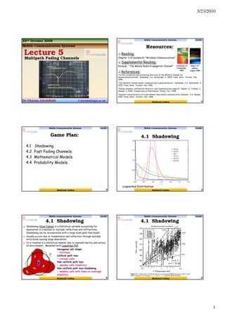
4.1 Shadowing
Mobile Communication Systems Oct09
Lognormal Distribution
Multipath Fading
Shadowing (Slow Fading) is a statistical variable accounting for
absorption in a medium or multiple reflections and diffractions.
Shadowing can be incorporated with a large scale path loss model.
Usually occurs due to transmission and reflection through multiple
structures causing large absorption.
It is treated in a statistical manner due to unpredictability and nature
of environment. Modelled with Lognormal PDF.
5
4.1 Shadowing
Mobile Communication Systems Oct09
Hexagonal cell shape:
- fictitious.
Uniform path loss:
- circular cells.
Non-uniform path loss
- amoeba cells (realistic).
Non-uniform path loss+shadowing
- amoeba cells with holes in coverage
(realistic).
Multipath Fading
4.1 Shadowing
Mobile Communication Systems Oct09
6Multipath Fading
2. 3/23/2010
2
Assumption: shadowing is dominated by the attenuation
from blocking objects.
Attenuation of for depth d:
s(d) = e−αd,
(α: attenuation constant).
Many objects:
s(dt) = e−α∑ di = e−αdt ,
dt = ∑ di is the sum of the random object depths
Cental Limit Theorem (CLT): αdt = log s(dt) ~ N(µ, σ).
log s(dt) is therefore log-normal
7
4.1 Shadowing
Mobile Communication Systems Oct09
Multipath Fading
General Proof: In measurements, the shadowing process
as a dB variable is a Gaussian RV, Xi. This means that
shadowing is a process that is Lognormal. Represent
Lognormal variable as Zi.
{ }( )
{ }( ) .
2σ
ZEZLog
exp
σ2πZ
1
Z
X
(X)P(Z)Pthen
2σ
XEX
exp
σ2π
1
(X)PSince
X.ZLogi.e.,eZisVariabletheoftionTransforma
2
Z
2
e
Z
XL
2
X
2
X
X
e
X
−−
=
∂
∂
=
−−
=
==
Gaussian PDF.
Lognormal PDF.
8
4.1 Shadowing
Mobile Communication Systems Oct09
= ∏∑ i
ie
i
i ZlogX
Shadowing:
Multipath Fading
Fit model to data:Fit model to data:
1. Path loss (K, γγγγ), d0 known:
• “Best fit” line through dB data.
• K obtained from measurements at d0.
• Exponent is MMSE estimate based on data.
• Captures mean due to shadowing.
2. Shadowing variance:
• Variance of data relative to path loss model
(straight line) with MMSE estimate for γγγγ.
9
Mobile Communication Systems Oct09
Multipath Fading
4.1 Shadowing
Why is ψdB a normally distributed? Hint: See slide 8.
10
Mobile Communication Systems Oct09
Multipath Fading
4.1 Shadowing
Outage probability:
Probability that Pr(d) (RX power at a distance d) < Pmin.
If outage occurs, it can be assumed user disconnected or
service cancelled.
For combined Path Loss and Shadowing Model, can write:
( ) ( )
γ−+−σ−= −
ψ
d
d
Log10KLog10PpQ1d,pp 0
1010Tmin
1
minout
( ) ( ) dB
0
1010
T
r
d
d
Log10KLog10dB
P
P
Ψ+
γ−=
),0(N~ 2
dB ψσΨRandom Variable
Mean
11
Mobile Communication Systems Oct09
Multipath Fading
4.1 Shadowing
Gaussian Q function
∫
∞
∂
−
π
=>=
S
2
y
2
y
exp
2
1
)ZX(p)S(Q
Z
p(X)
X
)S(Q1)ZX(p −=<
Useful function for Gaussian Distribution
{ }
∫
∑
∞
∞−
=∂
=∀
1X)X(p
1X)X(p Discrete
Continuous
Xm
12
Mobile Communication Systems Oct09
Multipath Fading
4.1 Shadowing
3. 3/23/2010
3
Gaussian Q function
Proof:
( )
∫
∞
∂
σ
−
−
σπ
=>
Z
2
2
m
X
2
XX
exp
2
1
)ZX(p
σ
−
= mXX
y
),X(N~X 2
m σ
( )SQ)ZX(p
y
2
y
exp
2
1
)ZX(p
mXZ
2
=>⇒
∂
−
π
=>⇒ ∫
∞
σ
−
σ
−
= mXZ
S
Gaussian RV
Change the Variable to
where
noting
)X(p
y
X
)X(p)y(p
⋅σ=
∂
∂
=
13
Mobile Communication Systems Oct09
Multipath Fading
4.1 Shadowing
In cellular communication, can define two outages – that due to
thermal noise, and that due to interference (from other cells).
Interference non trivial problem (since co-channel
interference from large number of additive components
depend on statistical path loss and shadowing properties of
each component).
Define noise: N = kTBw. N0 = kT = -174dBm/Hz for T = 290K.
A Noise outage at edge of cell can be defined as
PN(R)=P(Pr(dBm)
(d)<N(dBm)
)
where is the shadow margin.
( )
σ
=∂
σ
µ−
−
σπ
= ∫∞−
shad
N
2
2
P M
QX
2
)R(x
exp
2
1
)dBm(
)dBm(r
)dBm(Pshad N)R(M )dBm(r
−µ=
14
Mobile Communication Systems Oct09
Multipath Fading
4.1 Shadowing
4.2 Fast Fading Channels
Mobile Communication Systems Oct09
15
Network Analyzer
Multipath Fading
Mobile Communication Systems Oct09
4.2.1 Basic Wave Concepts
16
Sum of sinusoidal components results in another sinusoidal
component with certain amplitude and phase. This is basic
mechanism of fading.
Assumption: Components same frequency.
1φ
1A
2A 2φ
4.2 Fast Fading Channels
Multipath Fading
Mobile Communication Systems Oct09
4.2.1 Basic Wave Concepts
17
( ) ω tωφ = ( ) t
ω
ωφ
=
∂
∂
Important relation – first derivative (w.r.t. ω) of phase
yields time delay – it is also called group delay.
t
Phase response
GT
ω
φ
=
∂
∂
Simple Example: Adding two tones
with Time shift.
t
Σ
( ) t-jωtjω
ee1o/p −
+=
Group Delay
4.2 Fast Fading Channels
Multipath Fading
Mobile Communication Systems Oct09
4.2.1 Basic Wave Concepts
18
Phase delay dependent on frequency. In case of wave
packet (i.e. Such as a pulse) consisting of infinite record
of sinusoidal components with different frequencies, have
phase spectrum – i.e. A single time delay does not yield
equal phase delay on all sinusoidal tones in wave packet.
Brings us towards concepts like filtering.
t
4.2 Fast Fading Channels
Multipath Fading
4. 3/23/2010
4
Mobile Communication Systems Oct09
4.2.2 The Wireless Channel
19
Distortion:
-Fading,
-ISI due to propagation delays. Channel behaves like a filter.
-Channel usually non linear phase response = Phase distortion, ISI.
Model
4.2 Fast Fading Channels
Multipath Fading 20
4.2.3 Two Ray Model
Mobile Communication Systems Oct09
4.2 Fast Fading Channels
Typically a propagation channel – I.e. Fading large scale. For large d,
path difference is:
λd
hh4π
φ
d
h2h
d rtrt
=⇒≈
cd
h2h
T
t
φ rt
d == Time delay
Multipath Fading
Mobile Communication Systems Oct09
21
Wireless
Channel
•EM Models:
-Environment specific.
-Too detailed to be traceable.
•Behavioural Models:
-Estimate Physically Meaningful Parameters.
-Apply to Theoretical Model.
-Very Detailed but traceable.
•Measurement:
-Transmit well structured signal.
-Take “average” measurements.
-Leads to Linear System Approach.
4.2.4 Black Box Approach to Channel
Black BoxX(t) Y(t)
Deterministic
signal
Observed
output signal
4.2 Fast Fading Channels
Multipath Fading
Path loss is a natural phenomenon
occurring due to spreading of
electromagnetic waves radiated by
the transmitter (where the gain of
the antenna is non-singular).
The effect of path loss is such
that the SNR at the receiver
decreases monotonically with
distance from the transmitter.
Waves spread from the radiator in
space where the power flux density
decreases per unit distance.
Mobile Communication Systems Oct09
4.2.5 Introduction to Fast Fading
4.2 Fast Fading Channels
22Multipath Fading
Small-scale multipath fading
Wireless communication typically happens at very high carrier frequency. (eg.
fc = 900 MHz or 1.9 GHz for cellular)
Multipath fading due to constructive and destructive interference of the
transmitted waves. In the case of large scale and slow fading, we usually deal
with a small number of reflected waves. Means the fading is slowly varying
when traversing in environment.
If, however, due to scattering or many reflecting objects where the number
of waves constituting a wave bundle is very large (and scattering parameters
are random), then get fast fading in nonstationary environment.
Channel varies when mobile moves a distance of the order of the carrier
wavelength. This is about 0.3 m for 900 Mhz cellular. For vehicular speeds,
this translates to channel variation of the order of 100 Hz.
Primary driver behind wireless communication system design.
23
Mobile Communication Systems Oct09
4.2.5 Introduction to Fast Fading
4.2 Fast Fading Channels
Multipath Fading
Typical Urban Radio Channel:
Solid Line = Fast Fading.
Dashed Line = Variation in
Statistical Mean (Shadowing
or Slow Fading)
Fast Fading Rayleigh Channel
24
Mobile Communication Systems Oct09
4.2.5 Introduction to Fast Fading
4.2 Fast Fading Channels
Multipath Fading
5. 3/23/2010
5
25
Mobile Communication Systems Oct09
4.2.5 Introduction to Fast Fading
4.2 Fast Fading Channels
Path loss, shadowing => average signal power
loss
Fading around this average.
Subtract out average => fading modeled as
a zero-mean random process
Narrowband Fading channel: Each symbol is
long in time
The channel h(t) is assumed to be
uncorrelated across symbols => single “tap”
in time domain.
Fading w/ many scatterers: Central Limit
Theorem
In-phase (cosine) and quadrature (sine)
components of the snapshot r(0), denoted
as rI (0) and rQ(0) are independent
Gaussian random variables.
Envelope Amplitude:
Received Power:
Single Tap Fading
Base Station (BS)
Mobile Station (MS)
multi-path propagation
Path Delay
Power
path-2
path-2
path-3
path-3
path-1
path-1
Channel Impulse Response:
Channel amplitude |h| correlated at delays ττττ.
Each “tap” value @ kTs Rayleigh distributed
(actually the sum of several sub-paths)
26
Mobile Communication Systems Oct09
4.2.5 Introduction to Fast Fading
4.2 Fast Fading Channels
Multipath Fading
27
Mobile Communication Systems Oct09
4.2.5 Introduction to Fast Fading
4.2 Fast Fading Channels
Multipath Fading
RMS Delay Spread:
28
Mobile Communication Systems Oct09
4.2.5 Introduction to Fast Fading
4.2 Fast Fading Channels
Multipath Fading
Multipath: Time-Dispersion => Frequency Selectivity
The impulse response of the channel is correlated in the time-domain (sum of
“echoes”)
Manifests as a power-delay profile, dispersion in channel autocorrelation
function A(∆τ)
Equivalent to “selectivity” or “deep fades” in the frequency domain
Delay spread: τ ~ 50ns (indoor) – 1µs (outdoor/cellular).
Coherence Bandwidth: Bc = 500kHz (outdoor/cellular) – 20MHz (indoor)
Implications: High data rate: symbol smears onto the adjacent ones (ISI).
Multipath
effects
~ O(1µs)
29
Mobile Communication Systems Oct09
4.2.5 Introduction to Fast Fading
4.2 Fast Fading Channels
Multipath Fading 30
Mobile Communication Systems Oct09
Doppler Shift
4.2.5 Introduction to Fast Fading
tVX ∆=
Distance on x axis
( )cosθtVd =
Phase difference
( )[ ]
cosθ
c
V
f2π
t
φ
λ
cosθtV2π
dKφ
=
==
cosθ
c
V
ffd
=
Doppler Frequency Frequency
Multipath Fading
4.2 Fast Fading Channels
6. 3/23/2010
6
Doppler spread:
Note: opposite sign for doppler shift for the two waves
Effect is roughly like the product of two sinusoids
Mobile Communication Systems Oct09
Doppler Shift
4.2.5 Introduction to Fast Fading
31Multipath Fading
4.2 Fast Fading Channels
Doppler Spread: Effect
Fast oscillations of the order of GHz
Slow envelope oscillations order of 50 Hz => peak-to-zero every 5 ms
A.k.a. Channel coherence time (Tc) = c/4fv
5ms
32
Mobile Communication Systems Oct09
4.2.5 Introduction to Fast Fading
Multipath Fading
4.2 Fast Fading Channels
Mobile Communication Systems Oct09
4.2.5 Introduction to Fast Fading
33
Doppler Spread: Effect
Multipath Fading
4.2 Fast Fading Channels
Doppler: Non-Stationary Impulse Response.
Set of multipaths
changes ~ O(5 ms)
34
Mobile Communication Systems Oct09
4.2.5 Introduction to Fast Fading
4.2 Fast Fading Channels
Multipath Fading
35
The doppler power spectrum shows dispersion/flatness ~ doppler spread (100-200
Hz for vehicular speeds)
Equivalent to “selectivity” or “deep fades” in the time domain correlation
envelope.
Each envelope point in time-domain is drawn from Rayleigh distribution. But
because of Doppler, it is not IID, but correlated for a time period ~ Tc
(correlation time).
Doppler Spread: Ds ~ 100 Hz (vehicular speeds @ 1GHz)
Coherence Time: Tc = 2.5-5ms.
Implications: A deep fade on a tone can persist for 2.5-5 ms! Closed-loop
estimation is valid only for 2.5-5 ms.
Mobile Communication Systems Oct09
4.2.5 Introduction to Fast Fading
4.2 Fast Fading Channels
Doppler: Dispersion (Frequency) => Time-Selectivity
Multipath Fading
Fading Summary: Time-Varying Channel Impulse Response
#1: At each tap, channel gain |h| is a Rayleigh distributed r.v.. The random
process is not IID.
#2: Response spreads out in the time-domain (τ), leading to inter-symbol
interference and deep fades in the frequency domain: “frequency-selectivity”
caused by multi-path fading
#3: Response completely vanish (deep fade) for certain values of t: “Time-
selectivity” caused by doppler effects (frequency-domain dispersion/spreading) 36
Mobile Communication Systems Oct09
4.2.5 Introduction to Fast Fading
4.2 Fast Fading Channels
7. 3/23/2010
7
Dispersion-Selectivity Duality
37
Mobile Communication Systems Oct09
4.2.5 Introduction to Fast Fading
4.2 Fast Fading Channels
Dispersion-Selectivity Duality
38
Mobile Communication Systems Oct09
4.2.5 Introduction to Fast Fading
4.2 Fast Fading Channels
Power Delay Profile => Inter-Symbol interference
Higher bandwidth => higher symbol rate, and smaller time per-symbol
Lower symbol rate, more time, energy per-symbol
If the delay spread is longer than the symbol-duration, symbols will “smear” onto
adjacent symbols and cause symbol errors
Symbol
Time
Symbol Time
path-2
path-3
path-1
Path Delay
Power
Delay spread
~ 1 µµµµs
Symbol Error!
If symbol rate
~ Mbps
No Symbol Error! (~kbps)
(energy is collected
over the full symbol period
for detection)
39
Mobile Communication Systems Oct09
4.2.5 Introduction to Fast Fading
4.2 Fast Fading Channels
Effect of Bandwidth (No. taps) on MultiPath Fading
Effective channel depends on both physical environment and bandwidth.
Mobile Communication Systems Oct09
4.2.5 Introduction to Fast Fading
4.2 Fast Fading Channels
Multipath Fading
41
4.3 Mathematical Models
Mobile Communication Systems Oct09
Multipath Fading 42
Mobile Communication Systems Oct09
4.3.1 Summary
4.3 Mathematical Models
Multipath Fading
8. 3/23/2010
8
Mobile Communication Systems Oct09
4.3.1 Summary
4.3 Mathematical Models
43Multipath Fading
Wireless channels can be modeled as linear time-
varying systems:
where ai(t) and τi(t) are the gain and delay of path i.
The time-varying impulse response is:
Consider first the special case when the channel is
time-invariant:
44
Mobile Communication Systems Oct09
4.3.2 Physical Models
4.3 Mathematical Models
Multipath Fading
Communication takes place at
Processing takes place at baseband
45
Mobile Communication Systems Oct09
4.3.2 Physical Models
4.3 Mathematical Models
Multipath Fading
The frequency response of the system is shifted
from the passband to the baseband.
Each path is associated with a delay and a complex
gain.
Mobile Communication Systems Oct09
4.3.2 Physical Models
4.3 Mathematical Models
46Multipath Fading
Sampled baseband-equivalent channel model:
where hl is the lth complex channel tap,
and the sum is over all paths that fall in the delay bin
System resolves the multipaths up to delays of 1/W .
Delay bin. Some paths cannot be resolved
and the receiver would thus merge paths
on similar delay components.
This is discrete convolution.
47
Mobile Communication Systems Oct09
4.3.2 Physical Models
4.3 Mathematical Models
Multipath Fading
Fading occurs when there is destructive
interference of the multipaths that contribute
to a tap.
Delay spread
Coherence bandwidth
single tap, flat fading
multiple taps, frequency selective
Narrowband Model
Wideband Model
Usually calculated with
statistics
48
Mobile Communication Systems Oct09
4.3.2 Physical Models
4.3 Mathematical Models
Multipath Fading
9. 3/23/2010
9
Discrete symbol x[m] is the mth sample of the transmitted
signal; there are W samples per second.
Continuous time signal x(t), 1 s ≡ W discrete symbols
Each discrete symbol is a complex number;
It represents one (complex) dimension or degree of
freedom.
Bandlimited x(t) has W degrees of freedom per second.
Signal space of complex continuous time signals of
duration T which have most of their energy within the
frequency band [−W/2,W/2] has dimension
approximately WT.
Continuous time signal with bandwidth W can be
represented by W complex dimensions per second.
Degrees of freedom of the channel to be the dimension of
the received signal space of y[m]
Mobile Communication Systems Oct09
4.3.2 Physical Models
4.3 Mathematical Models
49Multipath Fading
Ideal Baseband Channel:
Multipath Fading Channel:
50
Mobile Communication Systems Oct09
4.3.2 Physical Models
4.3 Mathematical Models
Multipath Fading
Wideband Fading:
Received signal experiences:
Large-scale path losses
Shadowing
Small-scale rapid fading
Phase distortions
Doppler shift
Time dispersions
Mobile Communication Systems Oct09
4.3.2 Physical Models
4.3 Mathematical Models
51Multipath Fading
Doppler shift of the ith path
Doppler spread
Coherence time
Doppler spread is proportional to: The carrier frequency fc and the
angular spread of arriving paths.
where θi is the angle the direction of motion makes with the ith path
52
Mobile Communication Systems Oct09
4.3.2 Physical Models
4.3 Mathematical Models
Time Variations:
Multipath Fading
Channel Model as an FIR Filter.
( ) [ ]∑=
n
-n
ZnhZH
ωj
eZ =
( ) ( )∑=
n
-nT
s
s
ZnThZH
Mobile Communication Systems Oct09
4.3.2 Physical Models
4.3 Mathematical Models
53
Sample Continuous Time signal at integer intervals of Ts
Multipath Fading
Mobile Communication Systems Oct09
4.3.2 Physical Models
4.3 Mathematical Models
54Multipath Fading
10. 3/23/2010
10
55
Mobile Communication Systems Oct09
4.3.2 Physical Models
4.3 Mathematical Models
Multipath Fading
Coherence time Tc depends on carrier
frequency and vehicular speed, of the order of
milliseconds or more.
Delay spread Td depends on distance to
scatterers, of the order of nanoseconds
(indoor) to microseconds (outdoor).
Channel can be considered as time-invariant
over a long time scale.
56
Mobile Communication Systems Oct09
4.3.3 Typical Channels Underspread
4.3 Mathematical Models
Multipath Fading
57
4.4 Probability Models
Mobile Communication Systems Oct09
Used for analysis purposes in a wireless link.
Design and performance analysis based on statistical
ensemble of channels rather than specific physical channel.
Flat Fading Models: Many small Scattered Paths – Time
delays are not resolvable and the receiver sees many paths
merging on same (similar) time reference.
Selective Fading Models: Many small Scattered Paths
where the bandwidth of signal means components arriving at
different times are potentially resolvable. Causes Baseband
Signal distortion, ISI etc.
Can Combine Path loss and Shadowing with fast fading.
Multipath Fading
Has no Line of Sight component.
Start with Complex circular symmetric Gaussian Random Variable
N=X+jY. Let X = RcosΦ and Y=RsinΦ be I.I.D with E{X}=0 and
E{Y}=0. The envelope, R, given by the chi-squared random variable
with two degrees of freedom.
22
YXR +=
( )
−−= 22
22
yx
2σ
1
exp
2π
1
y)(x,p YX,
σ
y),(x,pJΦ)(R,p YX,ΦR, ⋅= RcosΦRsinΦ
sinΦcosΦ
Φ
Y
Φ
X
R
Y
R
X
Φ)(R,
Y)(X,
J
−
=
∂
∂
∂
∂
∂
∂
∂
∂
=
∂
∂
=
Change the Variables.
Joint PDF of x and y.
Jacobian of the transform.
Mobile Communication Systems Oct09
4.4.1 Rayleigh Flat Fading
4.4 Probability Models
58Multipath Fading
2π
1
RΦ)(R,p)(p
0
ΦR,Φ =∂= ∫
∞
Φ
−=⇒ 2
2
2
2σ
R
exp
2π
R
Φ)(R,p ΦR,
σ
ΦΦ)(R,p(R)p
2π
0
ΦR,R ∫ ∂=
−=
2
2
2
2σ
R
exp
σ
R
(R)pR⇒
Rayleigh Fading Distribution
The Phase of a Rayleigh RV is Uniformly
distributed.
59
Mobile Communication Systems Oct09
4.4.1 Rayleigh Flat Fading
4.4 Probability Models
Multipath Fading
−=
2
2
2
2σ
R
exp
σ
R
(R)pR
Rayleigh Fading Distribution:
•Describes the statistics in a fading
channel with no line of sight component.
•Also referred to as Fast Fading due to
scattering and Doppler spectrum.
2π
1
RΦ)(R,p)(p
0
ΦR,Φ =∂= ∫
∞
Φ
Mobile Communication Systems Oct09
4.4.1 Rayleigh Flat Fading
4.4 Probability Models
60
11. 3/23/2010
11
Level Crossing Rates and Fade Duration
•The LCR is defined as the
expected rate at which the
fading envelope (normalized to
RMS signal) crosses a specified
threshold in a positive
direction.
•The average Fade Duration is
the average period of time the
received signal is below a
threshold.LCR:
Number of level crossing per sec: r)rp(R,rN
0
R
&&&∫
∞
∂⋅=
−⋅
⋅⋅π=
2
RMSRMS
m
R
R
exp
R
R
f2NR
Joint density function
of r and at r = R.
Time derivative of
envelope r(t).
r&
fm = Doppler frequency, R = target value /
threshold, RRMS = Average Signal Power.
Mobile Communication Systems Oct09
4.4.1 Rayleigh Flat Fading
4.4 Probability Models
61
Average Fade Duration:
Fade duration in seconds:
−=∂= ∫ RMSR
R
R
exp-1rp(r)
0
⋅⋅π
−
−
=τ
RMS
m
2
RMS
R
R
f
1
R
R
exp
2
[ ]RrPr ≤=τ
RN
1
[ ] ∑τ=≤
i
ir
T
1
RrP
62
Level Crossing Rates and Fade Duration
Mobile Communication Systems Oct09
4.4.1 Rayleigh Flat Fading
4.4 Probability Models
( ) ( )∫
γ
γ γ∂γ=γ<γ=
0
0
0SOUT PPP
Defined as:
γ
γ
−−=γ∂
γ
γ
−
γ
= ∫
γ
s
0
0
s
s
s
s
OUT exp1exp
1
P
0
{ }OUTe
0
s
P1Log −−
γ
=γ
In Rayleigh fading:
Instantaneous SNR Minimum SNR for acceptable performance – in
BPSK with Pe = 10-3, Min SNR = 7dB.
Average SNR
63
Outage Probability
Mobile Communication Systems Oct09
4.4.1 Rayleigh Flat Fading
4.4 Probability Models
Multipath Fading
Will concentrate on Clarks and Jakes Model. Also
a Lognormal fading model will be studied.
These models essentially drive how we simulate
fast and slow fading channels on computer (using
Matlab for example). Essence is to capture the
baseband models:
∑=
π
⋅=
N
1i
)cos(θj2-
i
i
eAh(t)
∑=
⋅=
N
0i
i
light
c
i )tcos(θ
v
vf
j2-expAtUh(t) π)(
Where { }
{ } )(2πh(t)E
τ)(thh(t)E)R(
d0
2
*
τf
τ
ℑ⋅=
−⋅=
≤
−=
otherwise0,
ff,
f
f
1
1
πf
1
(f)P
d
2
d
d
hhwith
64
Mobile Communication Systems Oct09
4.4.2 Simulation Models
4.4 Probability Models
Multipath Fading
Scattering based model with N sources.
At any point, the received field is
Can be written in terms of I and Q
components
with
ωn = 2πfn, with fn the Doppler frequency, θn = 0 unless 3D model.
Cn a random scalar.
Mobile Communication Systems Oct09
4.4.2 Simulation Models
4.4 Probability Models
65
Model works on the assumption that I(t) and
Q(t) result in IID Gaussian Random variables.
If the number of sources, N, are large, central
limit theorem comes into play and hence both
I(t) and Q(t) are Gaussian variables.
Results in a Rayleigh fading distribution for the
envelope.
66
Mobile Communication Systems Oct09
4.4.2 Simulation Models
4.4 Probability Models
Multipath Fading