This document is a programming manual for MELSEC-Q/L/QnA programmable logic controllers that describes safety precautions, conditions of use, and instructions for creating sequential function chart (SFC) programs. It explains the components and configuration of SFC programs, including steps, transitions, and control instructions. It also provides specifications for applicable CPUs, device lists, processing times, and calculating program capacity. End users are instructed to read all manuals thoroughly to ensure proper use and safety.

![2
CONTENTS
SAFETY PRECAUTIONS . . . . . . . . . . . . . . . . . . . . . . . . . . . . . . . . . . . . . . . . . . . . . . . . . . . . . . . . . . . . . . . . . . . .1
CONDITIONS OF USE FOR THE PRODUCT . . . . . . . . . . . . . . . . . . . . . . . . . . . . . . . . . . . . . . . . . . . . . . . . . . . .1
INTRODUCTION. . . . . . . . . . . . . . . . . . . . . . . . . . . . . . . . . . . . . . . . . . . . . . . . . . . . . . . . . . . . . . . . . . . . . . . . . . .1
RELEVANT MANUALS . . . . . . . . . . . . . . . . . . . . . . . . . . . . . . . . . . . . . . . . . . . . . . . . . . . . . . . . . . . . . . . . . . . . . .5
TERMS . . . . . . . . . . . . . . . . . . . . . . . . . . . . . . . . . . . . . . . . . . . . . . . . . . . . . . . . . . . . . . . . . . . . . . . . . . . . . . . . . .6
CHAPTER 1 GENERAL DESCRIPTION 7
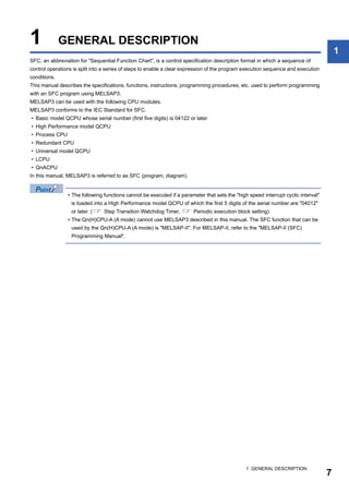
1.1 Description of SFC Program . . . . . . . . . . . . . . . . . . . . . . . . . . . . . . . . . . . . . . . . . . . . . . . . . . . . . . . . . . . . . . . 8
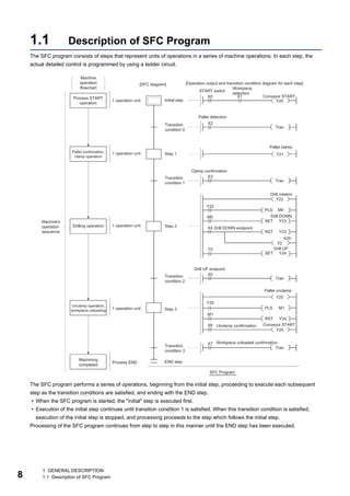
1.2 SFC (MELSAP3) Features. . . . . . . . . . . . . . . . . . . . . . . . . . . . . . . . . . . . . . . . . . . . . . . . . . . . . . . . . . . . . . . . . . 9
CHAPTER 2 SYSTEM CONFIGURATION 18
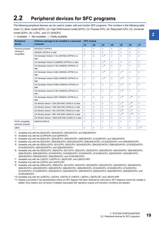
2.1 Applicable CPU modules . . . . . . . . . . . . . . . . . . . . . . . . . . . . . . . . . . . . . . . . . . . . . . . . . . . . . . . . . . . . . . . . . 18
2.2 Peripheral devices for SFC programs . . . . . . . . . . . . . . . . . . . . . . . . . . . . . . . . . . . . . . . . . . . . . . . . . . . . . . . 19
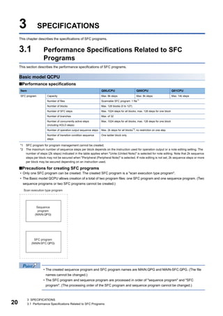
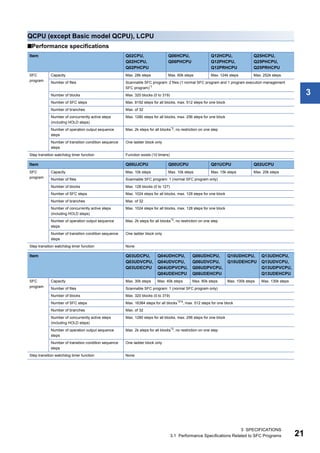
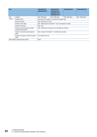
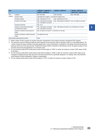
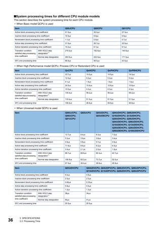
CHAPTER 3 SPECIFICATIONS 20
3.1 Performance Specifications Related to SFC Programs. . . . . . . . . . . . . . . . . . . . . . . . . . . . . . . . . . . . . . . . . 20
3.2 Device List . . . . . . . . . . . . . . . . . . . . . . . . . . . . . . . . . . . . . . . . . . . . . . . . . . . . . . . . . . . . . . . . . . . . . . . . . . . . . 27
3.3 Processing Time . . . . . . . . . . . . . . . . . . . . . . . . . . . . . . . . . . . . . . . . . . . . . . . . . . . . . . . . . . . . . . . . . . . . . . . . 35
Processing time for SFC program . . . . . . . . . . . . . . . . . . . . . . . . . . . . . . . . . . . . . . . . . . . . . . . . . . . . . . . . . . . . 35
Processing time for S(P).SFCSCOMR instruction and S(P).SFCTCOMR instruction. . . . . . . . . . . . . . . . . . . . . 39
3.4 Calculating the SFC Program Capacity. . . . . . . . . . . . . . . . . . . . . . . . . . . . . . . . . . . . . . . . . . . . . . . . . . . . . . 41
Method for calculating the SFC program capacity. . . . . . . . . . . . . . . . . . . . . . . . . . . . . . . . . . . . . . . . . . . . . . . . 41
Number of steps required for expressing the SFC diagram as SFC dedicated instructions . . . . . . . . . . . . . . . . 42
CHAPTER 4 SFC PROGRAM CONFIGURATION 43
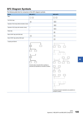
4.1 List of SFC Diagram Symbols . . . . . . . . . . . . . . . . . . . . . . . . . . . . . . . . . . . . . . . . . . . . . . . . . . . . . . . . . . . . . 44
4.2 Steps. . . . . . . . . . . . . . . . . . . . . . . . . . . . . . . . . . . . . . . . . . . . . . . . . . . . . . . . . . . . . . . . . . . . . . . . . . . . . . . . . . 47
Step (without step attribute). . . . . . . . . . . . . . . . . . . . . . . . . . . . . . . . . . . . . . . . . . . . . . . . . . . . . . . . . . . . . . . . . 47
Initial step . . . . . . . . . . . . . . . . . . . . . . . . . . . . . . . . . . . . . . . . . . . . . . . . . . . . . . . . . . . . . . . . . . . . . . . . . . . . . . 50
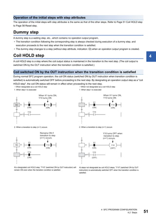
Dummy step . . . . . . . . . . . . . . . . . . . . . . . . . . . . . . . . . . . . . . . . . . . . . . . . . . . . . . . . . . . . . . . . . . . . . . . . . . . . 51
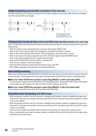
Coil HOLD step . . . . . . . . . . . . . . . . . . . . . . . . . . . . . . . . . . . . . . . . . . . . . . . . . . . . . . . . . . . . . . . . . . . . . . . . . . 51
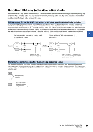
Operation HOLD step (without transition check) . . . . . . . . . . . . . . . . . . . . . . . . . . . . . . . . . . . . . . . . . . . . . . . . . 53
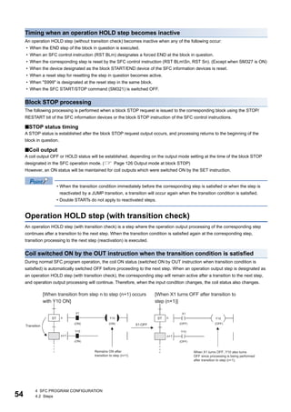
Operation HOLD step (with transition check) . . . . . . . . . . . . . . . . . . . . . . . . . . . . . . . . . . . . . . . . . . . . . . . . . . . 54
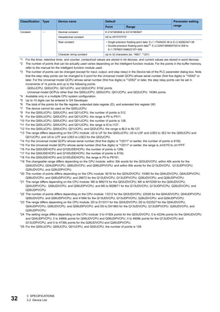
Reset step . . . . . . . . . . . . . . . . . . . . . . . . . . . . . . . . . . . . . . . . . . . . . . . . . . . . . . . . . . . . . . . . . . . . . . . . . . . . . . 56
Block START step (with END check). . . . . . . . . . . . . . . . . . . . . . . . . . . . . . . . . . . . . . . . . . . . . . . . . . . . . . . . . . 57
Block START step (without END check) . . . . . . . . . . . . . . . . . . . . . . . . . . . . . . . . . . . . . . . . . . . . . . . . . . . . . . . 58
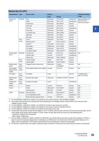
End step . . . . . . . . . . . . . . . . . . . . . . . . . . . . . . . . . . . . . . . . . . . . . . . . . . . . . . . . . . . . . . . . . . . . . . . . . . . . . . . 60
Instructions that cannot be used with operation outputs . . . . . . . . . . . . . . . . . . . . . . . . . . . . . . . . . . . . . . . . . . . 62
4.3 Transition . . . . . . . . . . . . . . . . . . . . . . . . . . . . . . . . . . . . . . . . . . . . . . . . . . . . . . . . . . . . . . . . . . . . . . . . . . . . . . 63
Serial transition . . . . . . . . . . . . . . . . . . . . . . . . . . . . . . . . . . . . . . . . . . . . . . . . . . . . . . . . . . . . . . . . . . . . . . . . . . 63
Selection transition . . . . . . . . . . . . . . . . . . . . . . . . . . . . . . . . . . . . . . . . . . . . . . . . . . . . . . . . . . . . . . . . . . . . . . . 66
Parallel transition. . . . . . . . . . . . . . . . . . . . . . . . . . . . . . . . . . . . . . . . . . . . . . . . . . . . . . . . . . . . . . . . . . . . . . . . . 69
Jump transition . . . . . . . . . . . . . . . . . . . . . . . . . . . . . . . . . . . . . . . . . . . . . . . . . . . . . . . . . . . . . . . . . . . . . . . . . . 73
Precautions when creating sequence programs for operation outputs (steps) and transition conditions . . . . . . 74
4.4 Controlling SFC Programs by Instructions (SFC Control Instructions). . . . . . . . . . . . . . . . . . . . . . . . . . . . 77
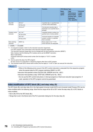
Step operation status check instruction (LD, LDI, AND, ANI, OR, ORI) [Sn/BLmSn]. . . . . . . . . . . . . . . . . . . . . 81
Forced transition check instruction (LD, LDI, AND, ANI, OR, ORI) [TRn/BLmTRn] . . . . . . . . . . . . . . . . . . . . . . 83
Block operation status check instruction (LD, LDI, AND, ANI, OR, ORI) [BLm] . . . . . . . . . . . . . . . . . . . . . . . . . 85](https://image.slidesharecdn.com/mitsubishisfc-220618170429-d21b8857/85/Mitsubishi-SFC-pdf-4-320.jpg)
![3
CONTENTS
Active step batch readout (MOV and DMOV) . . . . . . . . . . . . . . . . . . . . . . . . . . . . . . . . . . . . . . . . . . . . . . . . . . . 87
Active step batch readout (BMOV) . . . . . . . . . . . . . . . . . . . . . . . . . . . . . . . . . . . . . . . . . . . . . . . . . . . . . . . . . . . 90
Block START & END instructions (SET, RST) [BLm]. . . . . . . . . . . . . . . . . . . . . . . . . . . . . . . . . . . . . . . . . . . . . . 94
Block STOP and RESTART instructions (PAUSE, RSTART) [BLm]. . . . . . . . . . . . . . . . . . . . . . . . . . . . . . . . . . 96
Step START and END instructions (SET, RST) [Sn/BLmSn] . . . . . . . . . . . . . . . . . . . . . . . . . . . . . . . . . . . . . . . 99
Forced transition EXECUTE & CANCEL instructions (SET, RST) [TRn/BLmTRn] . . . . . . . . . . . . . . . . . . . . . 103
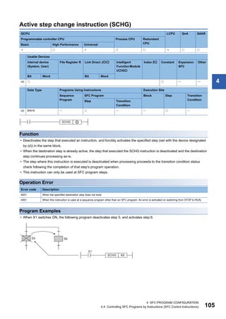
Active step change instruction (SCHG). . . . . . . . . . . . . . . . . . . . . . . . . . . . . . . . . . . . . . . . . . . . . . . . . . . . . . . 105
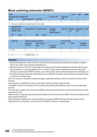
Block switching instruction (BRSET) . . . . . . . . . . . . . . . . . . . . . . . . . . . . . . . . . . . . . . . . . . . . . . . . . . . . . . . . . 106
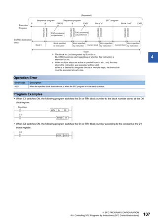
4.5 SFC Information Devices . . . . . . . . . . . . . . . . . . . . . . . . . . . . . . . . . . . . . . . . . . . . . . . . . . . . . . . . . . . . . . . . 108
Block START/END bit . . . . . . . . . . . . . . . . . . . . . . . . . . . . . . . . . . . . . . . . . . . . . . . . . . . . . . . . . . . . . . . . . . . . 109
Step transition bit. . . . . . . . . . . . . . . . . . . . . . . . . . . . . . . . . . . . . . . . . . . . . . . . . . . . . . . . . . . . . . . . . . . . . . . . 111
Block STOP/RESTART bit. . . . . . . . . . . . . . . . . . . . . . . . . . . . . . . . . . . . . . . . . . . . . . . . . . . . . . . . . . . . . . . . . 112
Block STOP mode bit . . . . . . . . . . . . . . . . . . . . . . . . . . . . . . . . . . . . . . . . . . . . . . . . . . . . . . . . . . . . . . . . . . . . 115
Continuous transition bit . . . . . . . . . . . . . . . . . . . . . . . . . . . . . . . . . . . . . . . . . . . . . . . . . . . . . . . . . . . . . . . . . . 117
Number of active steps register. . . . . . . . . . . . . . . . . . . . . . . . . . . . . . . . . . . . . . . . . . . . . . . . . . . . . . . . . . . . . 119
4.6 Step Transition Watchdog Timer . . . . . . . . . . . . . . . . . . . . . . . . . . . . . . . . . . . . . . . . . . . . . . . . . . . . . . . . . . 120
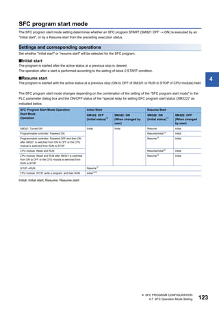
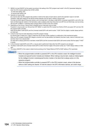
4.7 SFC Operation Mode Setting . . . . . . . . . . . . . . . . . . . . . . . . . . . . . . . . . . . . . . . . . . . . . . . . . . . . . . . . . . . . . 122
SFC program start mode. . . . . . . . . . . . . . . . . . . . . . . . . . . . . . . . . . . . . . . . . . . . . . . . . . . . . . . . . . . . . . . . . . 123
Block 0 START condition. . . . . . . . . . . . . . . . . . . . . . . . . . . . . . . . . . . . . . . . . . . . . . . . . . . . . . . . . . . . . . . . . . 125
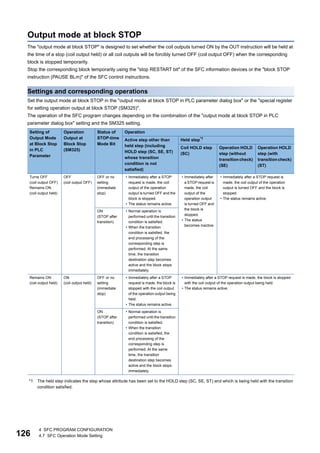
Output mode at block STOP . . . . . . . . . . . . . . . . . . . . . . . . . . . . . . . . . . . . . . . . . . . . . . . . . . . . . . . . . . . . . . . 126
Periodic execution block setting . . . . . . . . . . . . . . . . . . . . . . . . . . . . . . . . . . . . . . . . . . . . . . . . . . . . . . . . . . . . 128
Operation mode at double block START . . . . . . . . . . . . . . . . . . . . . . . . . . . . . . . . . . . . . . . . . . . . . . . . . . . . . . 129
Operation mode at transition to active step (double step START) . . . . . . . . . . . . . . . . . . . . . . . . . . . . . . . . . . 130
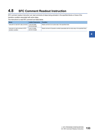
4.8 SFC Comment Readout Instruction. . . . . . . . . . . . . . . . . . . . . . . . . . . . . . . . . . . . . . . . . . . . . . . . . . . . . . . . 133
SFC comment readout instruction (S(P). SFCSCOMR) . . . . . . . . . . . . . . . . . . . . . . . . . . . . . . . . . . . . . . . . . . 134
SFC transition comment readout instruction (S(P). SFCTCOMR) . . . . . . . . . . . . . . . . . . . . . . . . . . . . . . . . . .140
CHAPTER 5 SFC PROGRAM PROCESSING SEQUENCE 147
5.1 Whole Program Processing of Basic Model QCPU . . . . . . . . . . . . . . . . . . . . . . . . . . . . . . . . . . . . . . . . . . . 147
Whole program processing sequence. . . . . . . . . . . . . . . . . . . . . . . . . . . . . . . . . . . . . . . . . . . . . . . . . . . . . . . . 147
5.2 QCPU (except Basic model QCPU), LCPU, QnACPU. . . . . . . . . . . . . . . . . . . . . . . . . . . . . . . . . . . . . . . . . . 148
Whole program processing sequence. . . . . . . . . . . . . . . . . . . . . . . . . . . . . . . . . . . . . . . . . . . . . . . . . . . . . . . . 148
Execution type designation by instructions . . . . . . . . . . . . . . . . . . . . . . . . . . . . . . . . . . . . . . . . . . . . . . . . . . . . 150
SFC program for program execution management. . . . . . . . . . . . . . . . . . . . . . . . . . . . . . . . . . . . . . . . . . . . . . 152
5.3 SFC Program Processing Sequence . . . . . . . . . . . . . . . . . . . . . . . . . . . . . . . . . . . . . . . . . . . . . . . . . . . . . . . 154
SFC program execution. . . . . . . . . . . . . . . . . . . . . . . . . . . . . . . . . . . . . . . . . . . . . . . . . . . . . . . . . . . . . . . . . . . 154
Block execution sequence. . . . . . . . . . . . . . . . . . . . . . . . . . . . . . . . . . . . . . . . . . . . . . . . . . . . . . . . . . . . . . . . . 156
Step execution sequence . . . . . . . . . . . . . . . . . . . . . . . . . . . . . . . . . . . . . . . . . . . . . . . . . . . . . . . . . . . . . . . . . 157
Continuous transition ON/OFF operation . . . . . . . . . . . . . . . . . . . . . . . . . . . . . . . . . . . . . . . . . . . . . . . . . . . . . 158
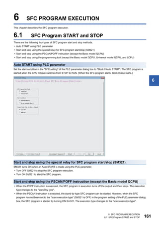
CHAPTER 6 SFC PROGRAM EXECUTION 161
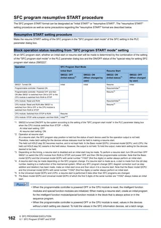
6.1 SFC Program START and STOP. . . . . . . . . . . . . . . . . . . . . . . . . . . . . . . . . . . . . . . . . . . . . . . . . . . . . . . . . . . 161
SFC program resumptive START procedure. . . . . . . . . . . . . . . . . . . . . . . . . . . . . . . . . . . . . . . . . . . . . . . . . . . 162
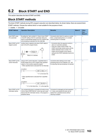
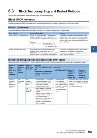
6.2 Block START and END . . . . . . . . . . . . . . . . . . . . . . . . . . . . . . . . . . . . . . . . . . . . . . . . . . . . . . . . . . . . . . . . . . 163
Block START methods. . . . . . . . . . . . . . . . . . . . . . . . . . . . . . . . . . . . . . . . . . . . . . . . . . . . . . . . . . . . . . . . . . . . 163
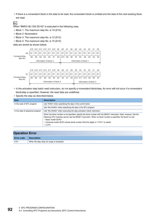
Block END methods . . . . . . . . . . . . . . . . . . . . . . . . . . . . . . . . . . . . . . . . . . . . . . . . . . . . . . . . . . . . . . . . . . . . . 164
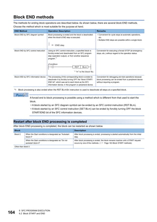
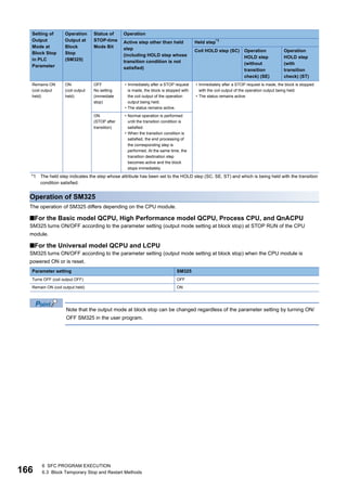
6.3 Block Temporary Stop and Restart Methods . . . . . . . . . . . . . . . . . . . . . . . . . . . . . . . . . . . . . . . . . . . . . . . . 165
Block STOP methods . . . . . . . . . . . . . . . . . . . . . . . . . . . . . . . . . . . . . . . . . . . . . . . . . . . . . . . . . . . . . . . . . . . . 165
Restarting a stopped block . . . . . . . . . . . . . . . . . . . . . . . . . . . . . . . . . . . . . . . . . . . . . . . . . . . . . . . . . . . . . . . . 167](https://image.slidesharecdn.com/mitsubishisfc-220618170429-d21b8857/85/Mitsubishi-SFC-pdf-5-320.jpg)
![5
RELEVANT MANUALS
e-Manual refers to the Mitsubishi FA electronic book manuals that can be browsed using a dedicated tool.
e-Manual has the following features:
• Required information can be cross-searched in multiple manuals.
• Other manuals can be accessed from the links in the manual.
• The hardware specifications of each part can be found from the product figures.
• Pages that users often browse can be bookmarked.
Manual name [manual number] Description Available
form
GX Developer Version 8 Operating Manual (SFC)
[SH-080374E]
Describes how to create SFC programs using the software package for
creating SFC programs.
Print book
PDF
GX Works2 Version1 Operating Manual (Common)
[SH-080779ENG]
Describes system configurations, parameter settings, online operations
(common to Simple project and Structured project) of GX Works2.
Print book
PDF
TYPE SW2IVD/NX-GPPQ GPP Software package Operating
Manual (SFC)
[IB-66776]
Describes how to create SFC programs using the software package for
creating SFC programs.
Print book
PDF
QnUCPU User's Manual (Function Explanation, Program
Fundamentals)
[SH-080807ENG]
Describes the functions, programming procedures, devices, etc.
necessary to create programs using the QCPU.
Print book
PDF
Qn(H)/QnPH/QnPRHCPU User's Manual(Function
Explanation, Program Fundamentals)
[SH-080808ENG]
Describes the functions, programming procedures, devices, etc.
necessary to create programs using the QCPU.
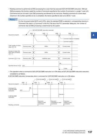
Print book
PDF
MELSEC-L CPU Module User's Manual (Function Explanation,
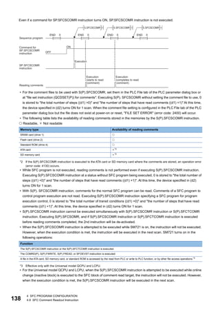
Program Fundamentals)
[SH-080889ENG]
Describes the functions required for programming, programming
methods, and devices.
Print book
e-Manual
PDF
MELSEC-Q/L Programming Manual (Common Instruction)
[SH-080809ENG]
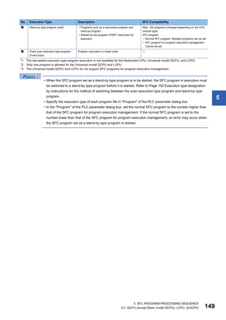
Describes how to use sequence instructions, basic instructions, and
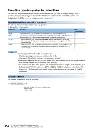
application instructions.
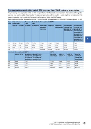
Print book
e-Manual
PDF
QnACPU Programming Manual (Common Instructions)
[SH-080810ENG]
Describes how to use sequence instructions, basic instructions, and
application instructions.
Print book
PDF
QnACPU Programming Manual (Fundamentals)
[IB-66614]
Describes the programming procedures, device names, parameters,
program types, etc. necessary to create programs.
Print book
PDF](https://image.slidesharecdn.com/mitsubishisfc-220618170429-d21b8857/85/Mitsubishi-SFC-pdf-7-320.jpg)
![1 GENERAL DESCRIPTION
1.2 SFC (MELSAP3) Features 17
1
Convenient trace function (when using GPPQ with QnACPU)
Blocks can be synchronized and traced, enabling the user to check the operation timing of multiple blocks. Moreover, the
trace results display screen can be switched to display the trace result details for each block.
The trace function can be used during using GPPQ with QnACPU.
[Trace Results Display]
Block
Active step numbers are
displayed (from smallest
number) for each block
Detailed display of specified block
[Trace Results Display]
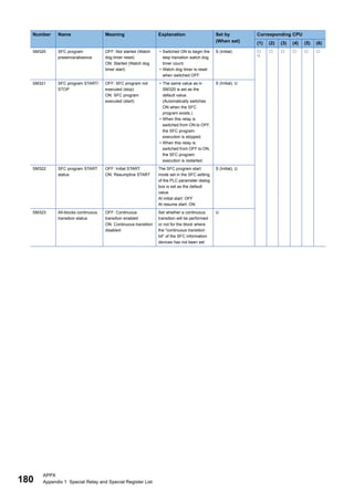
Block 1 Block number where
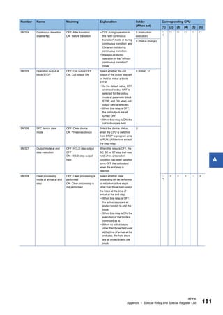
trace occurred
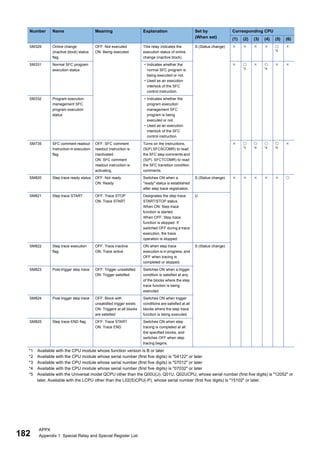
Active step number
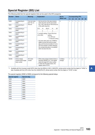
display](https://image.slidesharecdn.com/mitsubishisfc-220618170429-d21b8857/85/Mitsubishi-SFC-pdf-19-320.jpg)
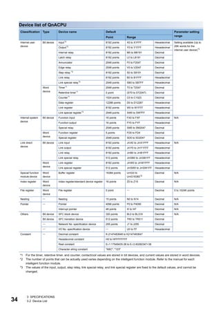
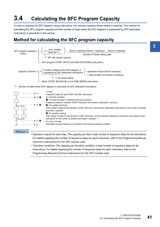
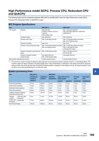
![3 SPECIFICATIONS
3.3 Processing Time 37
3
• LCPU
• QnACPU
*1 The HOLD step includes all of the coil hold steps and operation hold steps (with or without transition check). The Normal step represents
steps other than the above.
Ex.
[SFC system processing time calculation example]
Using the Q25HCPU as an example, the processing time for the SFC system is calculated as shown below, given the
following conditions.
• Designated at initial START
• Number of active blocks: 30 (active blocks at SFC program)
• Number of inactive blocks: 70 (inactive blocks at SFC program)
• Number of nonexistent blocks: 50 (number of blocks between 0 and the max. created block No. which have no SFC
program)
• Number of active steps: 60 (active steps within active blocks)
• Active step transition conditions: 60
• Steps with satisfied transition conditions: 10 (active steps (no HOLD steps) with satisfied transition conditions)
SFC system process time = (14.5 30) + (5.2 70) + (1.8 50)+ (10.6 60) + (4.3 60) + (56.2 10) + 46.6 =
2391.6s 2.40 ms
In this case, calculation using the equation shown above results in an SFC system processing time of 2.40 ms.
With the Q4ACPU, given the same conditions, the processing time would be 5.32 ms. The scan time is the total of the
following times: SFC system processing time, main sequence program processing time, processing time of ladder circuit
having transition conditions associated with SFC's active steps, and CPU module's END processing time.
The number of active steps, the number of transition conditions, and the number of steps with satisfied transition conditions
varies according to the conditions shown below.
• When transition condition is unsatisfied
• When transition condition is satisfied (without continuous transition)
• When transition condition is satisfied (with continuous transition)
Item L02SCPU,
L02SCPU-P
L02CPU,
L02CPU-P
L06CPU, L06CPU-P, L26CPU, L26CPU-P,
L26CPU-BT, L26CPU-PBT
Active block processing time coefficient 12.7s 8.5s 7.0s
Inactive block processing time coefficient 5.3s 3.8s 3.4s
Nonexistent block processing time coefficient 0.9s 1.2s 0.6s
Active step processing time coefficient 11.9s 8.7s 6.4s
Active transition processing time coefficient 3.4s 2.0s 1.6s
Transition condition-
satisfied step processing
time coefficient
With HOLD step
designation*1
86.7s 66.1s 42.7s
Normal step designation 106.9s 79.4s 52.0s
SFC end processing time 67.5s 44.7s 26.9s
Item Q4ACPU, Q4ARCPU,
Q2ASHCPU(S1)
Q3ACPU Q2ACPU(S1),
Q2ASCPU(S1)
Active block processing time coefficient 30.6s 61.2s 32.6s
Inactive block processing time coefficient 10.7s 21.3s 28.8s
Nonexistent block processing time coefficient 4.6s 9.2s 12.5s
Active step processing time coefficient 23.2s 46.4s 62.7s
Active transition processing time coefficient 9.4s 18.7s 25.2s
Transition condition-
satisfied step processing
time coefficient
With HOLD step
designation*1
137.2s 274.3s 370.4s
Normal step designation 122.5s 245.1s 330.9s
SFC end processing time 89.7s 179.3s 242.1s](https://image.slidesharecdn.com/mitsubishisfc-220618170429-d21b8857/85/Mitsubishi-SFC-pdf-39-320.jpg)
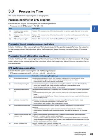
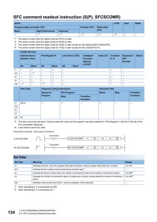
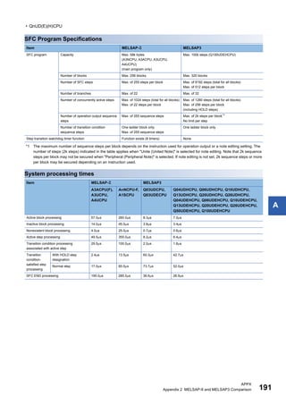
![3 SPECIFICATIONS
3.3 Processing Time 39
3
Processing time for S(P).SFCSCOMR instruction and
S(P).SFCTCOMR instruction
Processing time for S(P).SFCSCOMR instruction and S(P).SFCTCOMR instruction is shown below.
[Condition]
• The number of comments to be stored in the comment file: 1000
• Sequence steps in the SFC step in the SFC program: 1000 sequence steps
• The number of active steps: 40
*1 Indicates that the sequence steps in SFC steps consist of 800 sequence steps.
Instruction Condition High Performance model QCPU Process CPU Redundant
CPU
QnCPU QnHCPU
S(P).SFCSCOMR At instruction execution 280s 120s 120s 120s
At END processing (read 1 comment) 780s 350s 350s 350s
S(P).SFCTCOMR At instruction execution 300s 130s 130s 130s
At END
processing
(read 1
comment)
• Transition condition for serial
transition
• Transition condition after
selection branching
2.5ms 1.1ms 1.1ms 1.1ms
Transition
condition after
parallel
coupling
Number of
parallel
couplings: 2
4.5ms 2.0ms 2.0ms 2.0ms
Number of
parallel
couplings: 32
60.5ms*1
26.2ms 26.2ms 26.2ms
Instruction Condition Universal model QCPU
Q03UD(E)CPU Q04UD(E)HCPU, Q06UD(E)HCPU,
Q10UD(E)HCPU, Q13UD(E)HCPU,
Q20UD(E)HCPU, Q26UD(E)HCPU,
Q50UDEHCPU, Q100UDEHCPU
Min. Max. Min. Max.
S(P).SFCSCOMR At instruction execution 190s 193s 176s 177s
S(P).SFCTCOMR 190s 193s 176s 177s
Instruction Condition Universal model QCPU
Q03UD(E)CPU Q04UD(E)HCPU, Q06UD(E)HCPU,
Q10UD(E)HCPU, Q13UD(E)HCPU,
Q20UD(E)HCPU, Q26UD(E)HCPU,
Q50UDEHCPU, Q100UDEHCPU
SRAM card Flash card SRAM card Flash card
S(P).SFCSCOMR At END processing (read 1 comment) 3.3ms 4.5ms 2.5ms 4.0ms
S(P).SFCTCOMR At END
processing
(read 1
comment)
Transition condition for serial
transition
3.7ms 5.3ms 3.3ms 5.0ms
Transition condition after
selection branching
3.2ms 4.9ms 2.9ms 4.4ms
Transition
condition after
parallel
coupling
Number of
parallel
couplings: 2
4.0ms 5.7ms 3.6ms 5.1ms
Number of
parallel
couplings: 32
18.7ms 21.0ms 13.8ms 14.0ms](https://image.slidesharecdn.com/mitsubishisfc-220618170429-d21b8857/85/Mitsubishi-SFC-pdf-41-320.jpg)
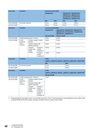
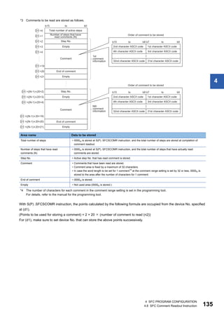
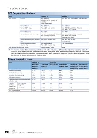
![42
3 SPECIFICATIONS
3.4 Calculating the SFC Program Capacity
Number of steps required for expressing the SFC diagram as SFC
dedicated instructions
The following table shows the number of steps required for expressing the SFC diagram as SFC dedicated instructions.
Name Ladder
Expression
Number of
Steps
Description Required Number of Steps
SFCP START instruction [SFCP] 1 Indicates the SFC program START 1 per program
SFCP END instruction [SFCPEND] 1 Indicates the SFC program END 1 per program
Block START instruction [BLOCK BLm] 1 Indicates the block START 1 per block
Block END instruction [BEND] 1 Indicates the block END 1 per block
Step START instruction [STEP Si] 2 Indicates the step START (" " varies
according to the step attribute)
1 per step
Transition START
instruction
[TRAN TRj] 2 Indicates the transition START (" " varies
according to the step attribute)
1 per transition condition
Coupling check
instruction
[TAND Si] 2 "Coupling completed" check occurs at parallel
coupling
"[Number of parallel couplings] - [1]"
per parallel coupling
Transition designation
instruction
[TSET Si] 2 Designates the transition destination step For serial transitions and selection
transitions, 1 per transition condition;
for parallel branching transitions, the
number of steps is the same as the
number of parallel couplings
Step END instruction [SEND] 1 Indicates the step / transition END 1 per step](https://image.slidesharecdn.com/mitsubishisfc-220618170429-d21b8857/85/Mitsubishi-SFC-pdf-44-320.jpg)
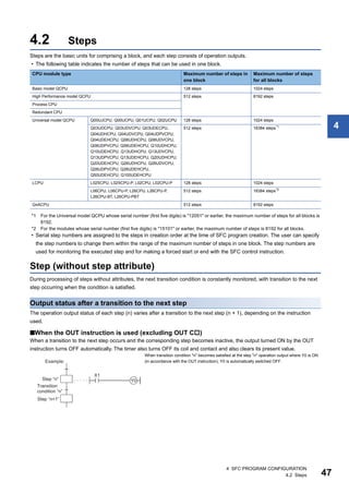
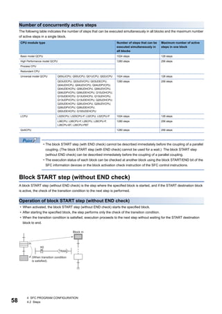
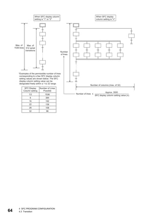
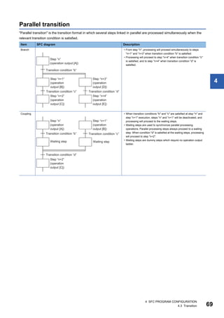
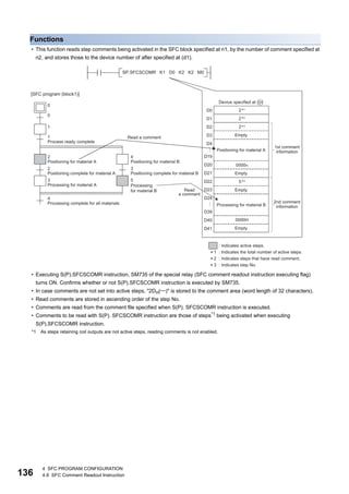
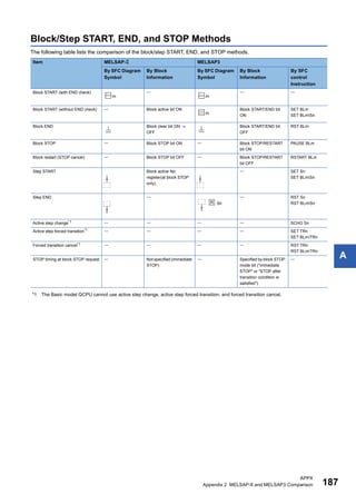
![4 SFC PROGRAM CONFIGURATION
4.3 Transition 63
4
4.3 Transition
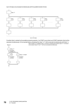
A transition is the basic unit for comprising a block, and is used by specifying a transition condition. A transition condition is a
condition for execution to proceed to the next step, and execution proceeds to the next step when the condition is satisfied.
Serial transition
"Serial transition" is the transition format in which processing proceeds to the step immediately below the current step when
the transition condition is satisfied.
A maximum of 512 serial transition steps can be described in each block.*1
Therefore, a maximum of 512 serial transitions (+)
can be described. However, there is a restriction on the number of lines as indicated below depending on the SFC display
column setting.
*1 128 for the Basic model QCPU, Q00UJCPU, Q00UCPU, Q01UCPU, Q02UCPU, L02SCPU, L02SCPU-P, L02CPU, and L02CPU-P.
Type Function Outline
Serial transition When the transition condition is satisfied, execution proceeds from the current step to the subsequent step.
Selection transition (branch/
coupling)
A single step branches out into multiple transition conditions. Among those multiple transition conditions, execution proceeds
to only the step in the line where the transition condition is satisfied first.
Parallel transition (branch/
coupling)
Execution simultaneously proceeds to all multiple steps that branch from a single step. When all steps immediately before a
coupling are activated, execution proceeds to the next step when the common transition condition is satisfied.
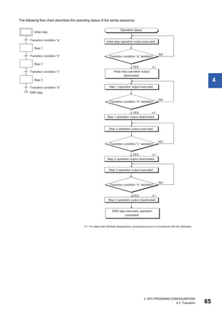
Jump transition When the transition condition is satisfied, execution proceeds to the specified step in the same block.
When transition condition "b" becomes satisfied at step "n" (operation output [A]) execution, operation output [A]
will be deactivated, and processing will proceed to step "n+1" (operation output [B]).](https://image.slidesharecdn.com/mitsubishisfc-220618170429-d21b8857/85/Mitsubishi-SFC-pdf-65-320.jpg)
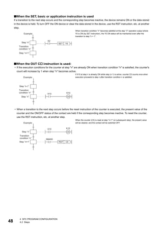
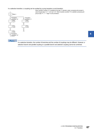
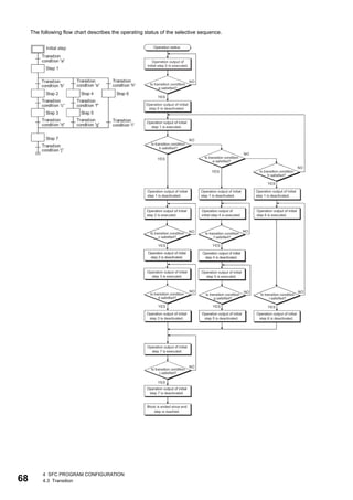
![66
4 SFC PROGRAM CONFIGURATION
4.3 Transition
Selection transition
A "selection transition" is the transition format in which several steps are coupled in a parallel manner, with processing
occurring only at the step where the transition condition is satisfied first.
Up to 32 steps can be available for selection in the selection transition format.
When two or more selection step transition conditions are satisfied simultaneously, the left-most condition will take
precedence.
Item SFC diagram Description
Branch • From step "n", processing will proceed to either step "n+1" or step
"n+2", depending on which transition condition ("b" or "c") is satisfied
first.
• If both transition conditions are satisfied simultaneously, the
condition to the left will take precedence. Step "n" will then be
deactivated.
• Subsequent processing will proceed from step to step in the selected
column until another parallel coupling selection occurs.
Coupling When the transition condition ("b" or "c") at the executed branch is
satisfied, the executed step ([A] or [B]) will be deactivated, and
processing will proceed to step "n+2".
If transition conditions "c" and "d" are satisfied simultaneously, the step "n+2"
operation output will be executed.](https://image.slidesharecdn.com/mitsubishisfc-220618170429-d21b8857/85/Mitsubishi-SFC-pdf-68-320.jpg)
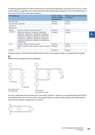
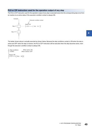
![4 SFC PROGRAM CONFIGURATION
4.3 Transition 73
4
Jump transition
A "jump transition" is a jump to a specified step within the same block which occurs when the transition condition is satisfied.
There are no restrictions regarding the number of jump transitions within a single block.
In the parallel transition format, only jumps in the vertical direction are possible at each of the branches.
Ex.
Jump transition program in vertical direction from branch to coupling
A program of a jump transition to another vertically branched ladder, a jump transition for exiting from a parallel branch, or a
jump transition to a parallel branch from outside a parallel branch cannot be created.
Ex.
Program for exiting from parallel branch (cannot be designated)
Do not specify a jump transition to the current step when the transition condition is satisfied as shown below.
SFC diagram Description
When condition "b" is satisfied at step "n" execution, step "n" (operation output [A]) is
deactivated, and processing proceeds to step "m".
n
n](https://image.slidesharecdn.com/mitsubishisfc-220618170429-d21b8857/85/Mitsubishi-SFC-pdf-75-320.jpg)
![4 SFC PROGRAM CONFIGURATION
4.4 Controlling SFC Programs by Instructions (SFC Control Instructions) 81
4
Step operation status check instruction (LD, LDI, AND, ANI, OR,
ORI) [Sn/BLmSn]
*1 The serial number (first five digits) shall be 04122 or later.
*2 Only step relay (S) can be used
Function
• Checks a specified step in a specified block to determine if the step is active or inactive.
• The contact status changes as described below depending on whether the specified step is inactive or active.
QCPU LCPU QnA Q4AR
Programmable controller CPU Process CPU Redundant
CPU
Basic High Performance Universal
*1
Usable Devices
Internal device
(System, User)
File Register R Link Direct J Intelligent
Function
Module UG
Index Z Constant
K, H
Expansion
SFC
BLmSn
Others
Bit Word Bit Word
(s)
*2
Data Type Programs Using Instructions Execution Site
Sequence
Program
SFC Program Block Step Transition
Condition
Step Transition
Condition
(s)
Device name
Contact of N/O Contact Instruction Contact of N/C Contact Instruction
Inactive OFF ON
Active ON OFF](https://image.slidesharecdn.com/mitsubishisfc-220618170429-d21b8857/85/Mitsubishi-SFC-pdf-83-320.jpg)
![4 SFC PROGRAM CONFIGURATION
4.4 Controlling SFC Programs by Instructions (SFC Control Instructions) 83
4
Forced transition check instruction (LD, LDI, AND, ANI, OR, ORI)
[TRn/BLmTRn]
Function
• Checks whether or not the specified transition condition of the specified block is specified for forced transition by the forced
transition EXECUTE instruction (SET BLmTRn).
• The contact status changes as described below depending on whether the specified transition condition is specified for a
forced transition or not.
QCPU LCPU QnA Q4AR
Programmable controller CPU Process CPU Redundant
CPU
Basic High Performance Universal
Usable Devices
Internal device
(System, User)
File Register R Link Direct J Intelligent
Function
Module UG
Index Z Constant
K, H
Expansion
SFC BLm/
TRn
Other
TRn
Bit Word Bit Word
(s)
Data Type Programs Using Instructions Execution Site
Sequence
Program
SFC Program Block Step Transition
Condition
Step Transition
Condition
(s) Device name
Contact of N/O Contact Instruction Contact of N/C Contact Instruction
When specified for forced transition ON OFF
When not specified for forced transition OFF ON](https://image.slidesharecdn.com/mitsubishisfc-220618170429-d21b8857/85/Mitsubishi-SFC-pdf-85-320.jpg)
![84
4 SFC PROGRAM CONFIGURATION
4.4 Controlling SFC Programs by Instructions (SFC Control Instructions)
• Specify the transition as described below.
• If the transition condition in question does not exist in the SFC program, it will remain OFF.
Program Examples
• The following program turns ON Y20 when transition condition 5 of block 3 is specified for a forced transition.
When transition condition is designated by operation output of block 3
When transition condition is designated by operation output of other than block 3 or sequence program
■Related Instructions
SFC control instructions
• Transition control instructions (SET TRn, SET BLmTRn): See Page 103 Forced transition EXECUTE & CANCEL
instructions (SET, RST) [TRn/BLmTRn].
• Transition control instructions (RST TRn, RST BLmTRn): See Page 103 Forced transition EXECUTE & CANCEL
instructions (SET, RST) [TRn/BLmTRn].
• Block switching instruction (BRSET): See Page 106 Block switching instruction (BRSET).
This instruction checks, from the first sequence step of the specified block in series, whether or not the
specified transition condition number is existed.
Because of this, processing time of the instruction differs depending on the program capacity of the specified
block (number of sequence steps), a maximum of hundred and several tens ms may be taken.
In case of occurring WDT error (error code: 5001), change the WDT setting value with the PLC RAS setting in
the PLC parameter.
Item Description
In the case of SFC program Use "Sn" when specifying the step in the current block.
Use "BLmSn" when specifying the step in another block in the SFC program.
In the case of sequence program Use "BLmSn" when executing the step activation check instruction.
When the block number is not specified, specify the block number with the BRSET instruction.](https://image.slidesharecdn.com/mitsubishisfc-220618170429-d21b8857/85/Mitsubishi-SFC-pdf-86-320.jpg)
![4 SFC PROGRAM CONFIGURATION
4.4 Controlling SFC Programs by Instructions (SFC Control Instructions) 85
4
Block operation status check instruction (LD, LDI, AND, ANI, OR,
ORI) [BLm]
*1 The serial number (first five digits) shall be 04122 or later.
Function
• Checks whether the specified block is active or inactive.
• The contact status changes as described below depending on whether the specified block is active or inactive.
• The contact is always OFF if the block that does not exist in the SFC program is specified.
• As the "BLm" device is treated as a virtual device, the contact on the monitor of a peripheral device does not
turn ON/OFF. If the internal device is ON, the coil instruction is switched ON for operations.
• In the High-speed Universal model QCPU and Universal model Process CPU, the number of steps in the
step activation check instruction increases by one step from that in the QnUDE(H)CPU.
QCPU LCPU QnA Q4AR
Programmable controller CPU Process CPU Redundant
CPU
Basic High Performance Universal
*1
Usable Devices
Internal device
(System, User)
File Register R Link Direct J Intelligent
Function
Module UG
Index Z Constant
K, H
Expansion
SFC
Other
BLm
Bit Word Bit Word
(s)
Data Type Programs Using Instructions Execution Site
Sequence
Program
SFC Program Block Step Transition
Condition
Step Transition
Condition
(s) Device name
Block Status Contact of N/O Contact Instruction Contact of N/C Contact Instruction
Active ON OFF
Inactive OFF ON](https://image.slidesharecdn.com/mitsubishisfc-220618170429-d21b8857/85/Mitsubishi-SFC-pdf-87-320.jpg)
![86
4 SFC PROGRAM CONFIGURATION
4.4 Controlling SFC Programs by Instructions (SFC Control Instructions)
Program example
• The following program turns ON Y20 when block 3 is active.
■Related Instructions
SFC control instructions
• Block START instruction (SET BLm), block END instruction (RST BLm): See Page 94 Block START & END instructions
(SET, RST) [BLm].
SFC diagram symbols
• Block START step ( m, m): See Page 57 Block START step (with END check) and Page 58 Block START step
(without END check).
SFC information device
• Block START/END bit: See Page 109 Block START/END bit.](https://image.slidesharecdn.com/mitsubishisfc-220618170429-d21b8857/85/Mitsubishi-SFC-pdf-88-320.jpg)
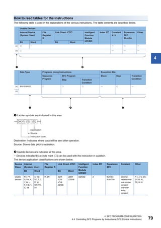
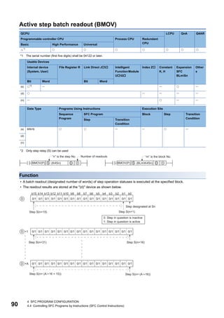
![4 SFC PROGRAM CONFIGURATION
4.4 Controlling SFC Programs by Instructions (SFC Control Instructions) 89
4
Operation Error
Program Examples
• The following program reads 32 active steps, starting from step 0 of block 3, to D0 and D1 when X0 turns ON.
When step is designated by operation output of block 3
When step is designated by operation output of other than block 3 or sequence program
■Related Instructions
SFC control instructions
• Block switching instruction (BRSET): See Page 106 Block switching instruction (BRSET).
• Step operation status check instruction (LD, LDI, AND, ANI, OR, ORI): See Page 81 Step operation status check instruction
(LD, LDI, AND, ANI, OR, ORI) [Sn/BLmSn].
• Active step batch readout instruction (BMOV): See Page 90 Active step batch readout (BMOV).
Error code Description
4101 • If exceeding the maximum step No. (8191) when block specification is not made (for the Universal model QCPU or LCPU)
• If specifying the stop which does not exist when block specification is not made (for the Universal model QCPU or LCPU)](https://image.slidesharecdn.com/mitsubishisfc-220618170429-d21b8857/85/Mitsubishi-SFC-pdf-91-320.jpg)
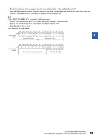
![4 SFC PROGRAM CONFIGURATION
4.4 Controlling SFC Programs by Instructions (SFC Control Instructions) 93
4
Program Examples
• The following program reads the active step status of 48 steps (3 words), starting from step 0 of block 3, to D0 - D2 when
X0 turns ON.
When step is designated by operation output of block 3
When step is designated by operation output of other than block 3 or sequence program
■Related Instructions
SFC control instructions
• Block switching instruction (BRSET): See Page 106 Block switching instruction (BRSET).
• Step operation status check instruction (LD, LDI, AND, ANI, OR, ORI): See Page 81 Step operation status check instruction
(LD, LDI, AND, ANI, OR, ORI) [Sn/BLmSn].
• Active step batch readout instruction (MOV, DMOV): See Page 87 Active step batch readout (MOV and DMOV).](https://image.slidesharecdn.com/mitsubishisfc-220618170429-d21b8857/85/Mitsubishi-SFC-pdf-95-320.jpg)
![94
4 SFC PROGRAM CONFIGURATION
4.4 Controlling SFC Programs by Instructions (SFC Control Instructions)
Block START & END instructions (SET, RST) [BLm]
*1 The serial number (first five digits) shall be 04122 or later.
Function
■Block START instruction (SET BLm)
• A specified block is forcibly activated independently and is executed from its initial step. When there are multiple initial
steps, all initial steps become active. When the bock START/END bit of the SFC information devices has been set, the
corresponding bit device changes from OFF to ON.
• If the specified block is already active when this instruction is executed, the instruction will be ignored (equivalent to the
NOP instruction), and processing will continue.
• While online change (inactive block) is executed to the specified block when this instruction is executed, the instruction will
be ignored (equivalent to the NOP instruction), and the online change processing will continue. (Universal model QCPU
whose serial number (first five digits) is "12052" or later, and the LCPU whose serial number (first five digits) is "15102" or
later only)
■Block END instruction (RST BLm)
• A specified block is forcibly deactivated independently. When there are active steps, all are deactivated and the coil outputs
are turned OFF. When the bock START/END bit of the SFC information devices has been set, the corresponding bit device
changes from ON to OFF.
• If the specified block is already inactive when this instruction is executed, the instruction will be ignored (equivalent to the
NOP instruction) and processing will continue.
QCPU LCPU QnA Q4AR
Programmable controller CPU Process CPU Redundant
CPU
Basic High Performance Universal
*1
Usable Devices
Internal device
(System, User)
File Register R Link Direct J Intelligent
FunctionModule
UG
Index Z Constant
K, H
Expansion
SFC
Other
BLm
Bit Word Bit Word
(d)
Data Type Programs Using Instructions Execution Site
Sequence
Program
SFC Program Block Step Transition
Condition
Step Transition
Condition
(d) Device name ](https://image.slidesharecdn.com/mitsubishisfc-220618170429-d21b8857/85/Mitsubishi-SFC-pdf-96-320.jpg)
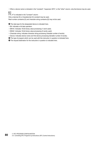
![96
4 SFC PROGRAM CONFIGURATION
4.4 Controlling SFC Programs by Instructions (SFC Control Instructions)
Block STOP and RESTART instructions (PAUSE, RSTART) [BLm]
*1 The serial number (first five digits) shall be 04122 or later.
Function
■Block STOP instruction (PAUSE)
• Executes a temporary stop at the specified block.
• As shown below, processing varies, depending on when the stop occurs and on the coil output status setting (designated
by OUT instruction).
QCPU LCPU QnA Q4AR
Programmable controller CPU Process CPU Redundant
CPU
Basic High Performance Universal
*1
Usable Devices
Internal device
(System, User)
File Register R Link Direct J Intelligent
FunctionModule
UG
Index Z Constant
K, H
Expansion
SFC
Other
BLm
Bit Word Bit Word
(d)
Data Type Programs Using Instructions Execution Site
Sequence
Program
SFC Program Block Step Transition
Condition
Step Transition
Condition
(d) Device name
Setting of
Output Mode
at Block Stop
in PLC
Parameter
Operation
Output at
Block Stop
(SM325)
Status of
STOP-time
Mode Bit
Operation
Active step other than
held step (including
HOLD step whose
transition condition is
not satisfied)
Held step*1
Coil HOLD step
(SC)
Operation HOLD
step (without
transitioncheck)
(SE)
Operation HOLD
step (with
transitioncheck)
(ST)
Turns OFF
(coil output OFF)
Remains ON
(coil output held)
OFF
(coil output OFF)
OFF or no
setting
(immediate
stop)
• Immediately after a STOP
request is made, the coil
output of the operation
output is turned OFF and the
block is stopped.
• The status remains active.
• Immediately after
a STOP request is
made, the coil
output of the
operation output
is turned OFF and
the block is
stopped.
• The status
becomes inactive.
• Immediately after a STOP request is
made, the coil output of the operation
output is turned OFF and the block is
stopped.
• The status remains active.
ON
(STOP after
transition)
• Normal operation is
performed until the transition
condition is satisfied.
• When the transition
condition is satisfied, the
end processing of the
corresponding step is
performed. At the same
time, the transition
destination step becomes
active and the block is
stopped before execution of
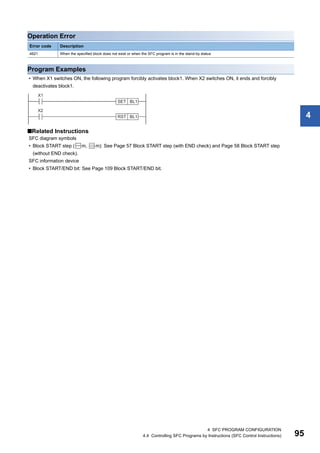
the operation output.](https://image.slidesharecdn.com/mitsubishisfc-220618170429-d21b8857/85/Mitsubishi-SFC-pdf-98-320.jpg)
![4 SFC PROGRAM CONFIGURATION
4.4 Controlling SFC Programs by Instructions (SFC Control Instructions) 99
4
Step START and END instructions (SET, RST) [Sn/BLmSn]
*1 The serial number (first five digits) shall be 04122 or later.
*2 Only step relay (S) can be used
Function
■Step START instruction (SET)
• A specified step at a specified block is activated forcibly. Operation at the block in question varies as follows, depending on
whether the block is active or inactive.
QCPU LCPU QnA Q4AR
Programmable controller CPU Process CPU Redundant
CPU
Basic High Performance Universal
*1
Usable Devices
Internal device
(System, User)
File Register R Link Direct J Intelligent
FunctionModule
UG
Index Z Constant
K, H
Expansion
SFC
BLmSn
Other
Sn
Bit Word Bit Word
(d) *2
Data Type Programs Using Instructions Execution Site
Sequence
Program
SFC Program Block Step Transition
Condition
Step Transition
Condition
(d) Device name
Item Description
When the specified block is
inactive:
The specified block is activated when the instruction is executed, and processing starts from the specified step.
Processing is performed as shown below when step 1 in block 1 is started in the sequence program.
When the block START/END bit of the SFC information devices has been set, the corresponding bit device changes from OFF
to ON.](https://image.slidesharecdn.com/mitsubishisfc-220618170429-d21b8857/85/Mitsubishi-SFC-pdf-101-320.jpg)
![4 SFC PROGRAM CONFIGURATION
4.4 Controlling SFC Programs by Instructions (SFC Control Instructions) 103
4
Forced transition EXECUTE & CANCEL instructions (SET, RST)
[TRn/BLmTRn]
Function
■Forced transition EXECUTE instruction (SET)
• A specified transition condition in a specified block is forcibly satisfied, and an unconditional transition is executed at the
step which precedes the condition.
• After execution of the instruction, the forced transition status remains effective until a reset instruction is executed.
■Forced transition CANCEL instruction (RST)
• Cancels the forced transition setting (designated by SET instruction) at a transition condition, and restores the transition
condition ladder created by the user.
■Specify the transition condition as described below.
QCPU LCPU QnA Q4AR
Programmable controller CPU Process CPU Redundant
CPU
Basic High Performance Universal
Usable Devices
Internal device
(System, User)
File Register R Link Direct J Intelligent
Function
Module UG
Index Z Constant
K, H
Expansion
SFC
BLmTRn
Other
TRn
Bit Word Bit Word
(d)
Data Type Programs Using Instructions Execution Site
Sequence
Program
SFC Program Block Step Transition
Condition
Step Transition
Condition
(d) Device name
Item Description
In the case of SFC program Use "TRn" when specifying the transition condition in the current block.
Use "BLm TRn" when specifying the transition condition in another block.
In the case of sequence program Use "BLm TRn" when executing the forced transition EXECUTE/CANCEL instruction in the sequence program.
When the block number is not specified, specify the block number with the BRSET instruction.](https://image.slidesharecdn.com/mitsubishisfc-220618170429-d21b8857/85/Mitsubishi-SFC-pdf-105-320.jpg)
![110
4 SFC PROGRAM CONFIGURATION
4.5 SFC Information Devices
Program example
Use the contact of the "block START/END bit" when a transition occurs after block 1 ends.
■Related Instructions
SFC control instructions
• Block START instruction (SET BLm), block END instruction (RST BLm): See Page 94 Block START & END instructions
(SET, RST) [BLm].
SFC diagram symbols
• Block START step ( m, m): See Page 57 Block START step (with END check) and Page 58 Block START step
(without END check).](https://image.slidesharecdn.com/mitsubishisfc-220618170429-d21b8857/85/Mitsubishi-SFC-pdf-112-320.jpg)
![114
4 SFC PROGRAM CONFIGURATION
4.5 SFC Information Devices
Related Instructions
SFC information device
• Block STOP mode bit: See Page 115 Block STOP mode bit.
SFC control instructions
• Block STOP instruction (PAUSE BLm) and block RESTART instruction (RSTART BLm): See Page 96 Block STOP and
RESTART instructions (PAUSE, RSTART) [BLm].](https://image.slidesharecdn.com/mitsubishisfc-220618170429-d21b8857/85/Mitsubishi-SFC-pdf-116-320.jpg)
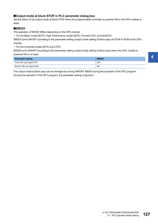
![116
4 SFC PROGRAM CONFIGURATION
4.5 SFC Information Devices
SM325 turns ON/OFF according to the parameter setting (output mode setting at block stop) at STOP to RUN
of the CPU module.
Turning OFF the output mode setting at block stop (coil output OFF): SM325 is OFF.
Remaining ON the output mode setting at block stop (coil output held): SM325 is ON.
Note that the output mode at block stop can be changed regardless of the parameter setting by turning ON/
OFF SM325 in the user program.
Related Instructions
SFC information device
• Block STOP/RESTART bit: See Page 112 Block STOP/RESTART bit.
SFC control instruction
• Block STOP instruction (PAUSE BLm): See Page 96 Block STOP and RESTART instructions (PAUSE, RSTART) [BLm].](https://image.slidesharecdn.com/mitsubishisfc-220618170429-d21b8857/85/Mitsubishi-SFC-pdf-118-320.jpg)
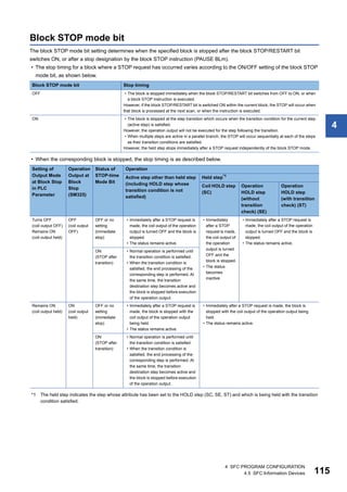
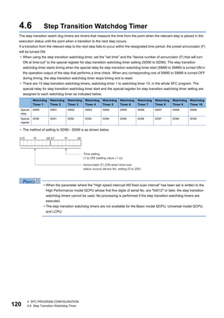
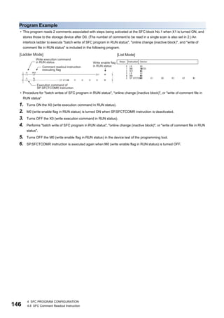
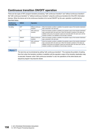
![118
4 SFC PROGRAM CONFIGURATION
4.5 SFC Information Devices
• The continuous transition disable flag (SM324) is always ON (turned ON automatically by the system at SFC program
execution) normally, but is OFF during continuous transition. Use of SM324 under the AND condition in a transition
condition disables a continuous transition.
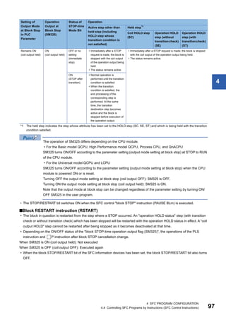
Ex.
[SFC program]
[Operation]
1. When M0 is ON, step 1 to step 4 are the targets of continuous transition.
2. Since SM324 is added as the AND condition to the transition condition following step 3, the transition condition following
step 3 is not satisfied after execution of step 3.
3. When step 3 is executed in the next scan, execution proceeds to step 4 in the same scan since SM324 is ON.
• When a jump transition or selection coupling causes a transition from multiple steps to one step, the
operation output of one step may be executed twice in a single scan. When the setting is "with continuous
transition" in the case as shown above, execution passes through step 3 twice in a single scan.
• In the case of "with continuous transition", a step start/end is made within one scan. Since the END
processing is not executed in this case, the coil output turned on by the OUT instruction in the operation
output is not reflected on the device. When the coil output is the Y output, actual output is not provided. In
addition, ON of the step relay cannot be detected.
• In the case of a program that uses a jump transition for looping, care must be taken when the transition
conditions in the loop are all satisfied during execution at the "with continuous transition" setting, since an
endless loop will occur within one scan, resulting in WDT Err. (No. 5001).](https://image.slidesharecdn.com/mitsubishisfc-220618170429-d21b8857/85/Mitsubishi-SFC-pdf-120-320.jpg)
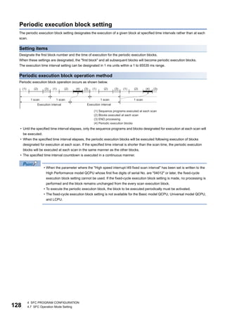
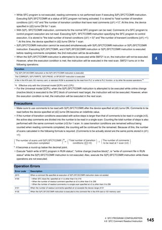
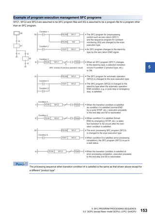
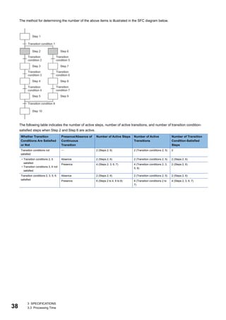
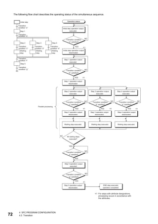
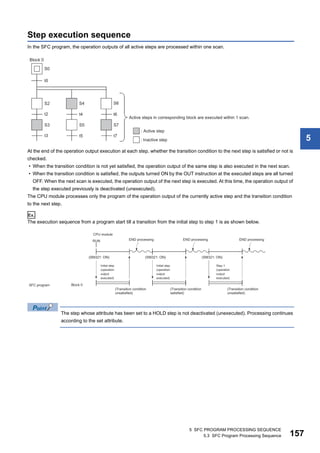
![154
5 SFC PROGRAM PROCESSING SEQUENCE
5.3 SFC Program Processing Sequence
5.3 SFC Program Processing Sequence
This section describes the SFC program processing sequence.
SFC program execution
The SFC program is executed once per scan.
Basic model QCPU
The Basic model QCPU executes a sequence program and then executes a SFC program. The program execution status is
shown below under the following condition.
[Condition]
• SFC program: Set to Auto START ON
[Program execution]
0](https://image.slidesharecdn.com/mitsubishisfc-220618170429-d21b8857/85/Mitsubishi-SFC-pdf-156-320.jpg)
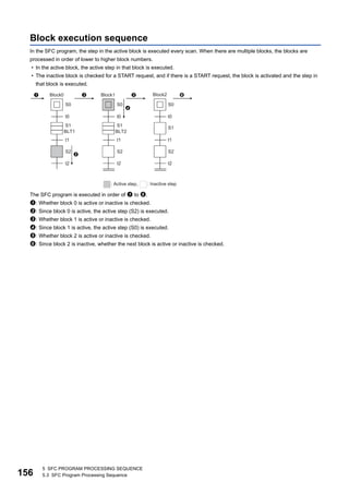
![5 SFC PROGRAM PROCESSING SEQUENCE
5.3 SFC Program Processing Sequence 155
5
QCPU (except Basic model QCPU), LCPU, QnACPU
The High Performance model QCPU, Process CPU, Redundant CPU, Universal model QCPU, LCPU, and QnACPU can
store multiple programs in the program memory and execute them. (Scan execution is enabled for two SFC programs (one
SFC program for program execution management and one normal SFC program).*1
Multiple programs are executed in the
order of the program setting in the PLC parameter dialog box.
[Condition]
• Program setting in PLC parameter dialog box
1: ABC (sequence) <scan>
2: DEF (SFC) <scan>
3: XYZ (sequence) <low speed>
• Low speed program time setting in parameter: 5ms
• SFC program: Set to Auto START ON
[Program execution]
*1 For the Universal model QCPU and LCPU, only one SFC program (one normal SFC program) can be scanned.
Refer to Page 161 SFC Program START and STOP for the SFC program start/stop method.](https://image.slidesharecdn.com/mitsubishisfc-220618170429-d21b8857/85/Mitsubishi-SFC-pdf-157-320.jpg)

![186
APPX
Appendix 2 MELSAP-II and MELSAP3 Comparison
SFC Control Instructions
The SFC control instruction shown below are available at MELSAP3. MELSAP-II has no SFC control instructions.
*1 Indicates the corresponding CPU module type name.
(1) Basic model QCPU
(2) High Performance model QCPU
(3) Process CPU
(4) Redundant CPU
(5) Universal model QCPU, LCPU
(6) QnACPU
*2 Available with the Universal model QCPU whose serial number (first five digits) is "13102" or later.
Name Ladder Expression Function Corresponding CPU*1
(1) (2) (3) (4) (5) (6)
Step status (active/
inactive) check
instruction
[LD, AND, OR, LDI, ANI, ORI] Sn Executes a check to determine if a specified
step at a specified block is active or inactive.
[LD, AND, OR, LDI, ANI, ORI] BLmSn
Forced transition
check instruction
[LD, AND, OR, LDI, ANI, ORI] TRn Checks a specified step in a specified block
to determine if the transition condition (by
transition control instruction) for that step
was satisfied forcibly or not.
[LD, AND, OR, LDI, ANI, ORI] BLmTRn
Block operation status
check instruction
[LD, AND, OR, LDI, ANI, ORI] BLm Checks a specified block to determine if it is
active or inactive.
Active steps batch
readout instruction
MOV(P) K4Sn (d) Active steps in a specified block are read to a
specified device as bit information.
MOV(P) BLmK4Sn (d)
DMOV(P) K8Sn (d)
DMOV(P) BLmK8Sn (d)
BMOV(P) K4Sn (d) Kn
BMOV(P) BLmK4Sn (d) Kn
Block START
instruction
SET BLm A specified block is forcibly started
(activated) independently, and is executed
from its initial step.
Block END instruction RST BLm A specified block is forcibly ended
(deactivated).
Block STOP instruction PAUSE BLm A specified block is temporarily stopped.
Block restart
instruction
RSTART BLm The temporary stop status at a specified
block is canceled, with operation resuming
from the STOP step.
Step control instruction SET Sn A specified block is forcibly started
(activated) independently, and is executed
from a specified step.
SET BLmSn
RST Sn A specified step in a specified block is
forcibly ended (deactivated).
RST BLmSn
SCHG (d) The instruction execution step is deactivated,
and a specified step is activated.
Transition control
instruction
SET TRn A specified transition condition at a specified
block is forcibly satisfied.
SET BLmTRn
RST TRn The forced transition at a specified transition
condition in a specified block is canceled.
RST BLmTRn
Block switching
instruction
BRSET (s) Blocks subject to the "*1" SFC control
instruction are designated.
*2
](https://image.slidesharecdn.com/mitsubishisfc-220618170429-d21b8857/85/Mitsubishi-SFC-pdf-188-320.jpg)


![205
WARRANTY
Please confirm the following product warranty details before using this product.
1. Gratis Warranty Term and Gratis Warranty Range
If any faults or defects (hereinafter "Failure") found to be the responsibility of Mitsubishi occurs during use of the product
within the gratis warranty term, the product shall be repaired at no cost via the sales representative or Mitsubishi Service
Company.
However, if repairs are required onsite at domestic or overseas location, expenses to send an engineer will be solely at
the customer's discretion. Mitsubishi shall not be held responsible for any re-commissioning, maintenance, or testing
on-site that involves replacement of the failed module.
[Gratis Warranty Term]
The gratis warranty term of the product shall be for one year after the date of purchase or delivery to a designated place.
Note that after manufacture and shipment from Mitsubishi, the maximum distribution period shall be six (6) months, and
the longest gratis warranty term after manufacturing shall be eighteen (18) months. The gratis warranty term of repair
parts shall not exceed the gratis warranty term before repairs.
[Gratis Warranty Range]
(1) The range shall be limited to normal use within the usage state, usage methods and usage environment, etc., which
follow the conditions and precautions, etc., given in the instruction manual, user's manual and caution labels on the
product.
(2) Even within the gratis warranty term, repairs shall be charged for in the following cases.
1. Failure occurring from inappropriate storage or handling, carelessness or negligence by the user. Failure caused
by the user's hardware or software design.
2. Failure caused by unapproved modifications, etc., to the product by the user.
3. When the Mitsubishi product is assembled into a user's device, Failure that could have been avoided if functions
or structures, judged as necessary in the legal safety measures the user's device is subject to or as necessary by
industry standards, had been provided.
4. Failure that could have been avoided if consumable parts (battery, backlight, fuse, etc.) designated in the
instruction manual had been correctly serviced or replaced.
5. Failure caused by external irresistible forces such as fires or abnormal voltages, and Failure caused by force
majeure such as earthquakes, lightning, wind and water damage.
6. Failure caused by reasons unpredictable by scientific technology standards at time of shipment from Mitsubishi.
7. Any other failure found not to be the responsibility of Mitsubishi or that admitted not to be so by the user.
2. Onerous repair term after discontinuation of production
(1) Mitsubishi shall accept onerous product repairs for seven (7) years after production of the product is discontinued.
Discontinuation of production shall be notified with Mitsubishi Technical Bulletins, etc.
(2) Product supply (including repair parts) is not available after production is discontinued.
3. Overseas service
Overseas, repairs shall be accepted by Mitsubishi's local overseas FA Center. Note that the repair conditions at each FA
Center may differ.
4. Exclusion of loss in opportunity and secondary loss from warranty liability
Regardless of the gratis warranty term, Mitsubishi shall not be liable for compensation to:
(1) Damages caused by any cause found not to be the responsibility of Mitsubishi.
(2) Loss in opportunity, lost profits incurred to the user by Failures of Mitsubishi products.
(3) Special damages and secondary damages whether foreseeable or not, compensation for accidents, and
compensation for damages to products other than Mitsubishi products.
(4) Replacement by the user, maintenance of on-site equipment, start-up test run and other tasks.
5. Changes in product specifications
The specifications given in the catalogs, manuals or technical documents are subject to change without prior notice.](https://image.slidesharecdn.com/mitsubishisfc-220618170429-d21b8857/85/Mitsubishi-SFC-pdf-207-320.jpg)