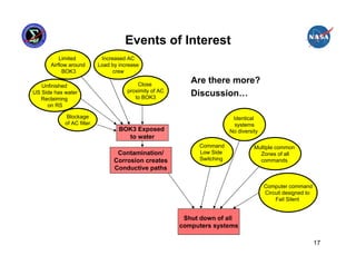
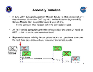
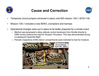
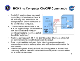
This presentation summarizes the June 2007 anomaly where all six Russian Segment computers on the International Space Station shut down. It describes the timeline of events, impact to ISS operations, and temporary mitigation steps taken. The root cause was determined to be moisture contamination in the BOK3 command unit that provided commands to the computers. Design changes were implemented to improve redundancy, including separating redundant systems beyond the influence of single failures and ensuring systems are designed to fail safely.

![“Risk Based” Approach
• The NESC’s Design Development Test and Evaluation (DDT&E)
Considerations for Safe and Reliable Human Rated Spacecraft Systems
(Volume-II) focuses on creating a system that mitigates specific threats or
risks to a given implementation
[Predictability: subsystem’s fault
1 response consistent with system
Eliminate the architecture]
threat/risk from the
design
2
Reduce the
Likelihood by
[Reduce the threat/risk to
decoupling system 3 Mitigate the
interactions
equal probability/impact of consequences by
other system threats/risks] adding diverse
redundancy
[Diverse redundant systems not
simultaneously susceptible to threat/risk]
13](https://image.slidesharecdn.com/mitchell-davis-120723085302-phpapp01/85/Mitchell-davis-13-320.jpg)
![Conclusion
• Regardless of requirements, constraints and operational considerations
momentary undesirable environments or interactions will occur eventually.
• How each and every individual subsystem responds to probable threats
must be aligned in a system architecture to achieve a predictable and
robust system.
• A reliable and safe system is created by a process that mitigates probable
threats by considering the sphere of influence of each threat relative to the
specific design implementation.
• A “common cause” threat/risk can be any threat/risk that impacts more than
one system in a given implementation.
• For redundancy system architectures, the threat/risk mitigation
effectiveness is a function of physical separation and/or dissimilar design
implementation.
– A dissimilar design has the advantage of reduced functionally to focus on safely
and reliability. [less functions = less complexity = more predictability]
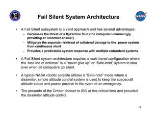
• Fail Silent system architecture requires a multi-tiered configuration where
the “last line of defense” is a “never give up” or “Safe-hold” system to
provide critical functions when all computers go silent.
16](https://image.slidesharecdn.com/mitchell-davis-120723085302-phpapp01/85/Mitchell-davis-16-320.jpg)