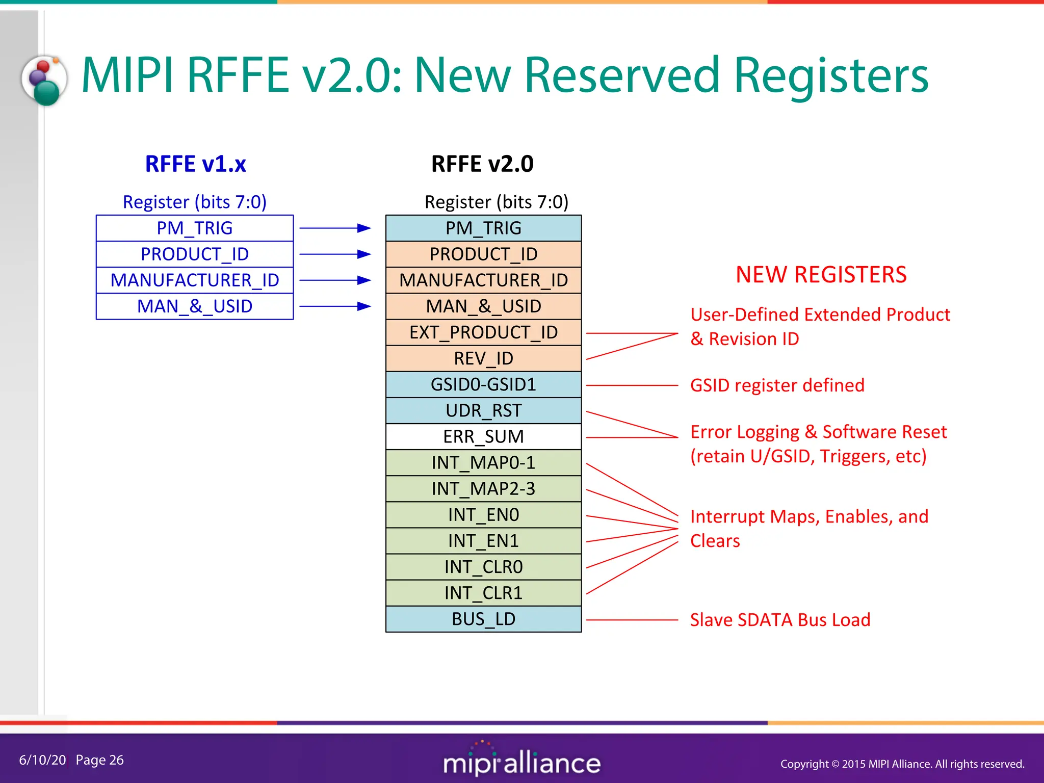
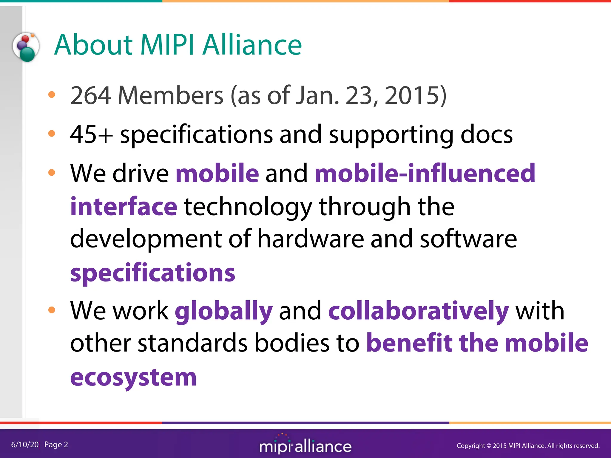
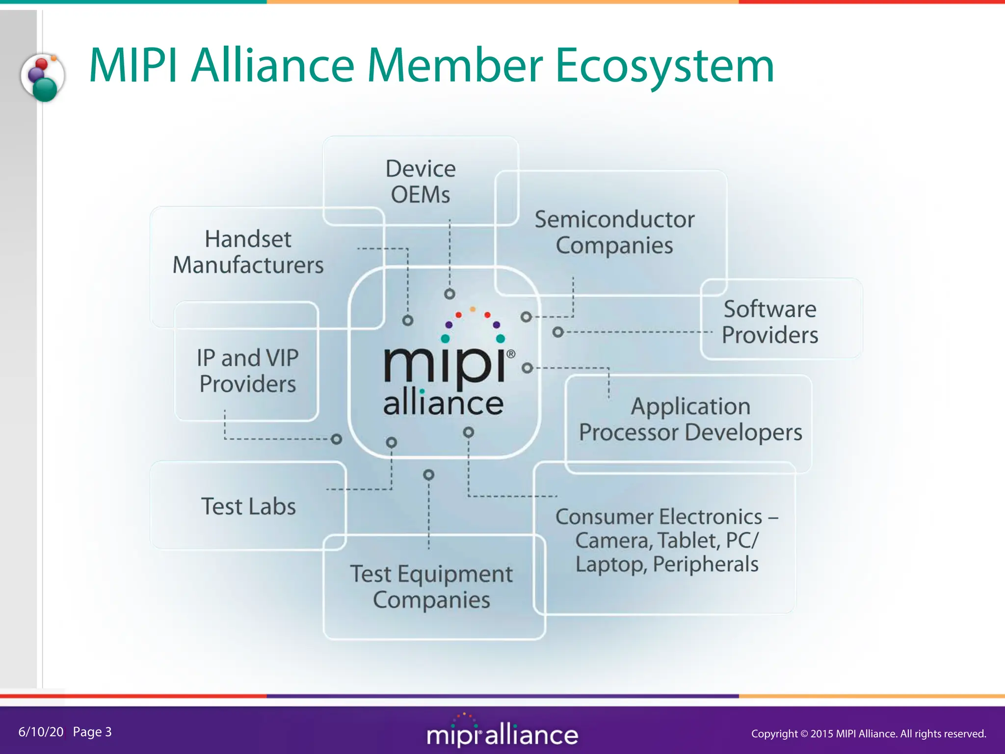
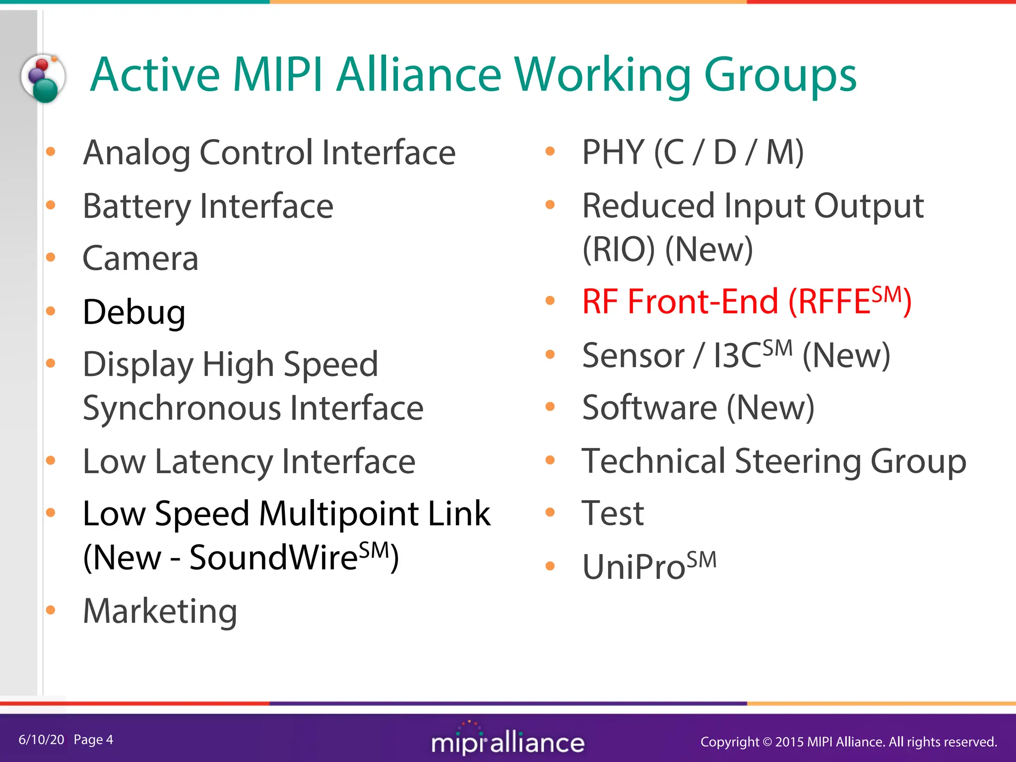
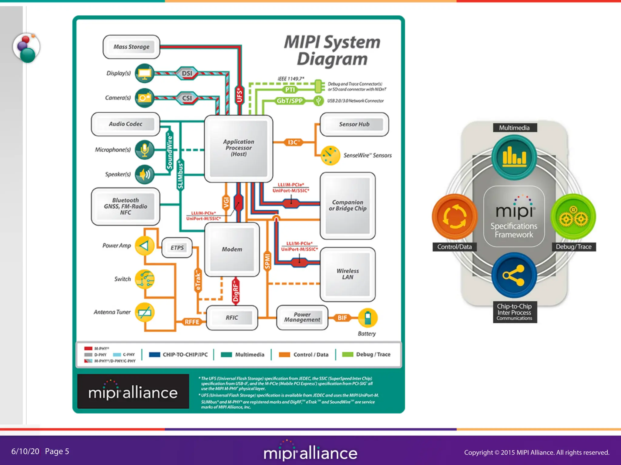
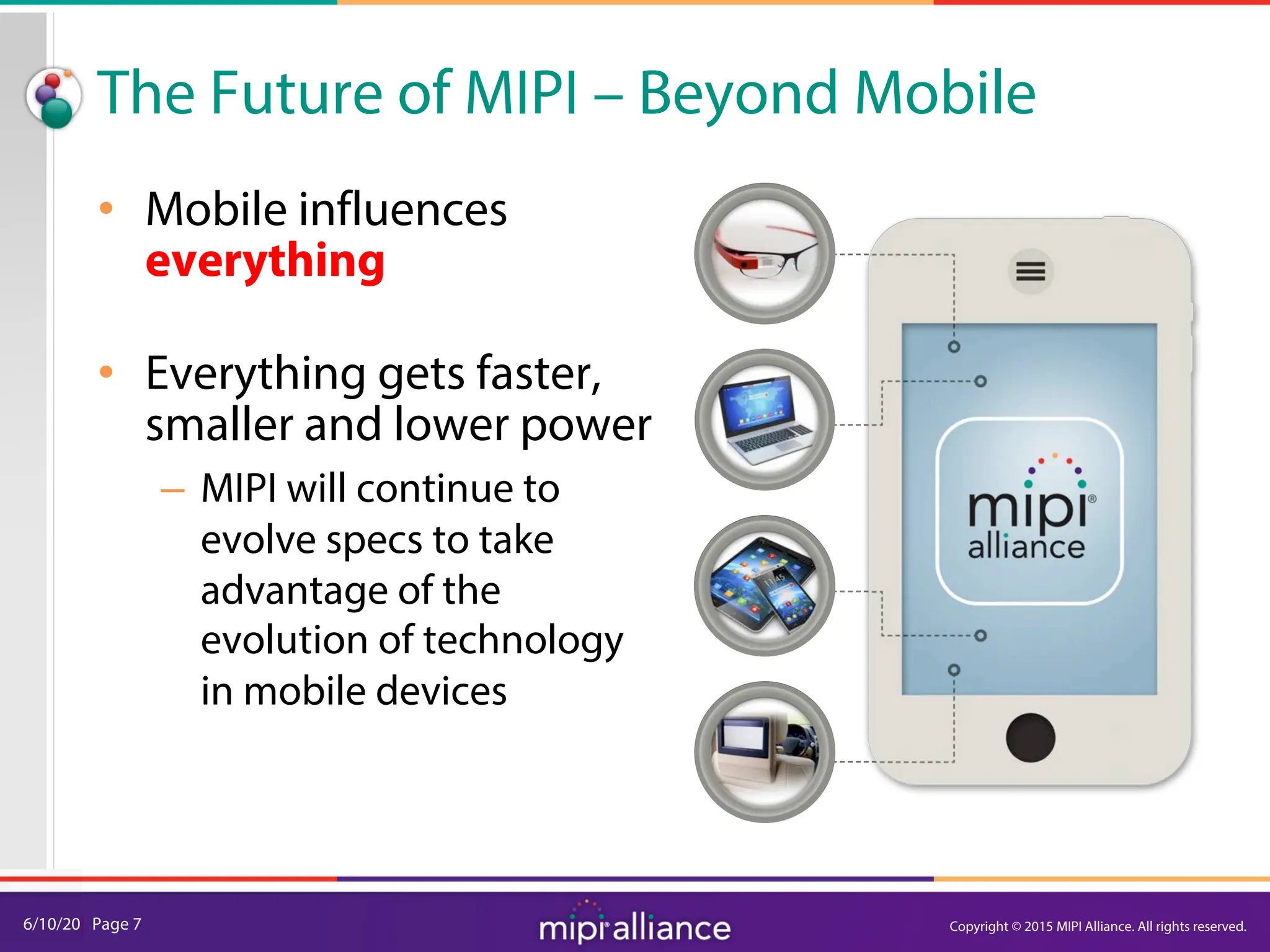
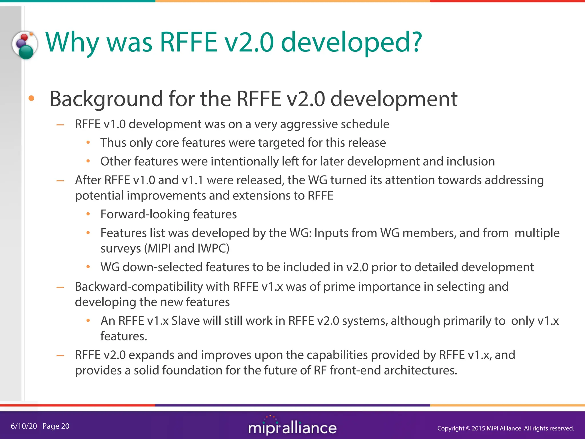
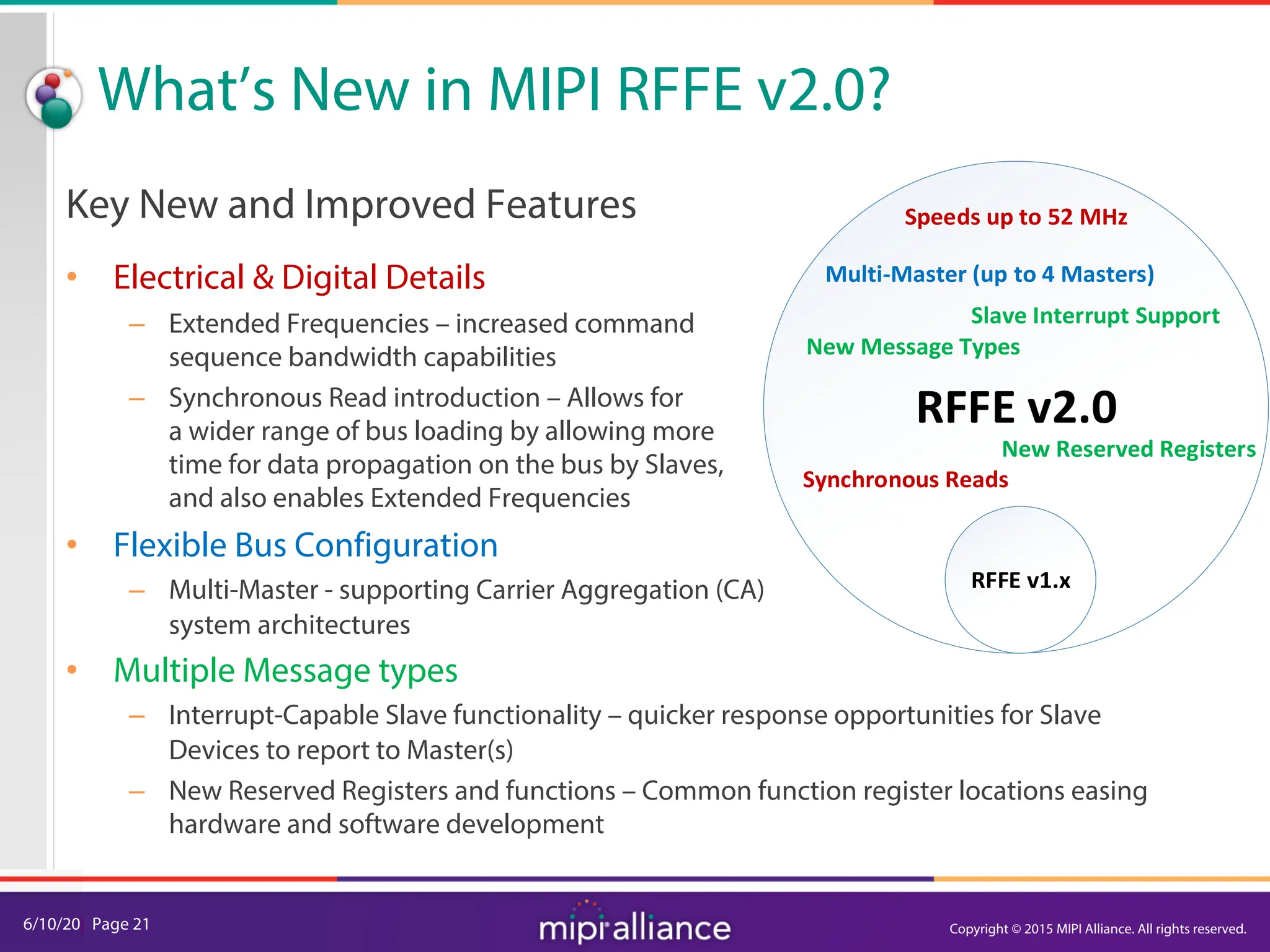
The document provides an overview of the MIPI RFFE v2.0 webinar, discussing the new features and implementation benefits for RF front-end control. It highlights key improvements such as multi-master support, extended bus frequencies, and interrupt-capable slave functionality, which enhance device interoperability and performance. The MIPI Alliance continues to evolve its specifications to meet the growing demands of mobile technology.

![6/10/20| Page 16
RFFE Control Bus Overview
The components of a RFFE message.
• SSC : Start Sequence Condition
• Command Frame
– SA[3:0] = Slave Address addressing 15 slaves, SA=0 will broadcast to ALL slaves
• Parity calculated & inserted for each Frame in a Command Sequence
• Data or Address Frame
• Bus Park Cycle
Basic Register Write and Read Commands
Description SSC Command Frame Data Frame
Register Write
1 0
SA[3:0] 0 1 0
0 0 0 0 0
P Data[7:0] P BP
Address[4:0]
1 1 1 1 1
Register Read SA[3:0] 0 1 1
0 0 0 0 0
P BP Data[7:0] P BP
Address[4:0]
1 1 1 1 1](https://image.slidesharecdn.com/mipi-webinar-rffev2-240717143302-e2519ef6/75/MIPI-Webinar-An-Overview-of-RFFEv2-0-pdf-17-2048.jpg)
![6/10/20| Page 25
Interrupt
Mapping
Configure
More Slaves?
Interrupt
Enable
Interrupt
Summary
Indication
Any active
Interrupt?
Interrupt
Identification
Interrupt
Clear
Master determines
Time available to scan
ICS Start
Need to
Identify?
Y
Y
Y
N
N
N
Extended / Ext Long
Command Sequence
Interrupt
Summary
&
Identification
Command
Sequence
Interrupt
Servicing
Extended / Ext Long
Command Sequence
Extended / Ext Long
Command Sequence
KEY
Action in
Master
Portion of
ICS Cmd
Sequence
ICS
Decision in
Master
ICS
Command
Sequence
ICS-Related
Function/
Action
Extended
Command
Sequence
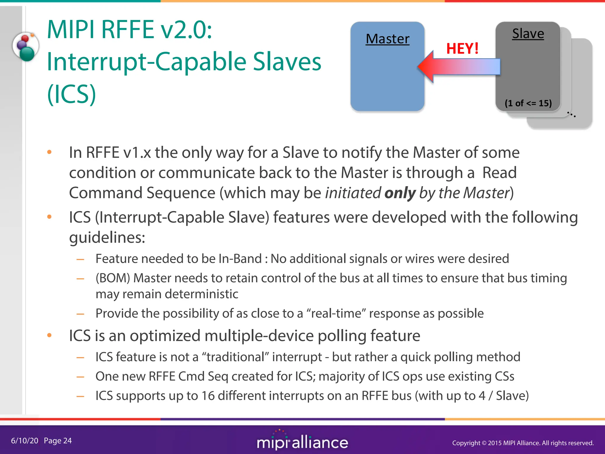
MIPI RFFE v2.0: Interrupt-Capable Slaves (ICS)
Configuration Phase
[Only needed at ICS set up
or configuration changes]
Quick Interrupt Scan
(Of All ICS Enabled Slaves)
[Optimized for Time-Minimized
Polling of Any/All Interrupt
Requests]
Identification / Servicing /
Clearing Phase
[Used only when Interrupts must be
Identified, Serviced, and/or Cleared]
ICS Flow Chart
(from RFFE v2.0 Spec)
Copyright © 2015 MIPI Alliance. All rights reserved.](https://image.slidesharecdn.com/mipi-webinar-rffev2-240717143302-e2519ef6/75/MIPI-Webinar-An-Overview-of-RFFEv2-0-pdf-26-2048.jpg)