SlideShare a Scribd company logo
1 of 13
Download to read offline
METHOD OF MODELLING HELICAL GEAR ON SOLID WORKS SOFTWARE
1 | P a g e 4 S e p t e m b e r 2 0 1 4
1) First step: Draw all necessary parameter sketches in one stretch and make them construction
(hidden) entities ,except a feature entity see the sketch below .
WE CAN ADD FORMULAE TO EACH DIMENSIONAL PARAMETER
EX:“MODULE” AND “NO OF TEETH” ARE VERIABLE AND ALL OTHER PARAMETERS CAN BE FARMULATED
REALTIONS ACCORDING TO “WESTERMANN TABLE” (FOR METAL TRADE) ,REVISED SECOND EDITION
PAGE NO 70
PITCH = MODULE X PI
ADDENDUM CIRCLE DIA=PITCH CIRCLE DIA + (2XMODULE)
PITCH CIRCLE DIA = NO OF TEETH X MODULE
DEDUNDUM CIRCLE DIA = 1.2 X MODULE
METHOD OF MODELLING HELICAL GEAR ON SOLID WORKS SOFTWARE
2 | P a g e 4 S e p t e m b e r 2 0 1 4
2) SECOND STEP: CALCULATION OF TEETH FROFILE
TEETH THICKNESS DEPENDS ON
CIRCULAR THICKNESS ANGLE =(( 360/NO OF TEETH)X0.5 )DRAW 2 HIDDEN LINES FROM THE
CENTER OF SKETCH.
METHOD OF MODELLING HELICAL GEAR ON SOLID WORKS SOFTWARE
3 | P a g e 4 S e p t e m b e r 2 0 1 4
DRAW TANGENT LINE “D” TO PITCH CIRCLE FORM INTERSECTION OF LINE “B” AND “PITCH
CIRCLE”
DRAW “E” 20* ANGLE LINE TO TANGENT LINE “D” FROM INTERSECTION OF LINE “B” AND PITCH
CIRCLE
DRAW CIRCLE “F” WHOSE DIA IS 1/4 OF PITCH CIRCLE DIA
DRAW TANGENT CERCLE “G” TO LINE “E” (PREASSURE ANGLE LINE20DEG)
DRAW CIRCLE “H” ,WHOSE CENTER IS AT (FROM INTERSECTION POINT “I” AND CIRCLE “G”) TO
THE INTERSECTION POINT OF LINE “B” AND “PITCH CIRCLE DIA”
THIS IS ABSOLUTELY A ANALYTICAL METHOD TO GET A FORM AND SHAPE
3) THIRD STEP:EXTRUDE DEDUNDUM TO REQUIRED HEIGHT AND ADD IT TO EQUATIONS IN SOLID
WORKS
KNOW ADDING PARAMETERS TO” EQUATIONS “ IN SOLID WORKS ,SO THAT ANY ONE CAN USE
MY METHOD TO GET STANDERD HELICAL GEAR (YOU CAN MODIFY AT ANY POINT OF TIME IT
IS LIKE A CEMENT ON IRON(IT WILL NEVER LEAVE RELATION).
METHOD OF MODELLING HELICAL GEAR ON SOLID WORKS SOFTWARE
4 | P a g e 4 S e p t e m b e r 2 0 1 4
4) Fourth step: see the fig below in TOOLS menu we have “Equations) click on that you get
Equations dialog box to add parameters and equations
Before Adding Dimensional Parameters we can change the name of parameter ,so that we can
easily identify particular parameter of a model in equations dialog box.See fig below.
First pick the dimension, it changes color from black to green then click on more properties,
dialog box appears .Hear in the Name Box We can add ADDENDUM .This will make easy to
identify the particular parameters to Edit.
METHOD OF MODELLING HELICAL GEAR ON SOLID WORKS SOFTWARE
5 | P a g e 4 S e p t e m b e r 2 0 1 4
METHOD OF MODELLING HELICAL GEAR ON SOLID WORKS SOFTWARE
6 | P a g e 4 S e p t e m b e r 2 0 1 4
ADDENDUM is added to the Equations and we can Equate that parameter to the module and
pitch circle as we have discussed earlier .in page 1
METHOD OF MODELLING HELICAL GEAR ON SOLID WORKS SOFTWARE
7 | P a g e 4 S e p t e m b e r 2 0 1 4
Same way WE can add parameters of Features also see the fig.
Double click on feature it will turn green and dimension of feature (eg : Extrude 6mm)
Will appear in blue see fig below
Just pick the dimension and change the name as thickness of gear
In same way that will be added to the equations and we can relate it to module by formulae
Eg: Thickness = 6 x Module
See below fig go to “Tools” “Equations “pick feature dimension and “add “it will ask value .We
can know add relation or equation by 2 methods
Write equations by manually typing dimension name as in the “dimension property manager”
Or we can pick other parameters (dimensional) to complete the equation. Like this we can add
Equations of features and modify them at any point of time.
Feature Dim
METHOD OF MODELLING HELICAL GEAR ON SOLID WORKS SOFTWARE
8 | P a g e 4 S e p t e m b e r 2 0 1 4
5) FIFTH STEP: AFTER ADDING ALL PARAMETERS TO “EQUATIONS GETTING GEAR TEETH PROFILE
Fig .BELOW SHOWS GEAR TOOTH PROFILE.
A) DRAW ARC CONSTRAINED TO CIRCLE “H”.
B) MIRROR IT BY LINE “A”.
C) COMPLETE THE PROFILE USING ‘ADDENDUM” AND “DEDUNDUM” CIRCLES.
D) SWEEP PROFILE WITH HELIX TO GET ONE TEETH.
6) SIXTH STEP: TO GET A HELIX ON PERIPHERY OF DEDUNDUM WE CAN USE FORMULAE
LEAD = tan(helix angle) x π(dia of dedundum circle)
WHERE HELIX ANGLE IS CONSTANT AND DEDUNDUM IS EQUATED BY FORMULAE
TO CREATE HELIX OF LENGTH EQUAL TO GEAR THIKNESS ABOVE FAORMUALE IS USED.
SEE BELOW fig.
DEDENDUM
ADDENDUM
ARC
METHOD OF MODELLING HELICAL GEAR ON SOLID WORKS SOFTWARE
9 | P a g e 4 S e p t e m b e r 2 0 1 4
a) Draw circle on face of dia equal to dedundum
b) Use helix command (defined by height and pitch).see fig below
c) In height 6mm(thickness of gear) will be equated
d) In pitch the value 469.2703262 is equated by formulae (LEAD = tan(helix angle) x π(dia of
dedundum circle)
e) Start angle is 90◦
So we get helix profile like this.see equation table also.
METHOD OF MODELLING HELICAL GEAR ON SOLID WORKS SOFTWARE
10 | P a g e 4 S e p t e m b e r 2 0 1 4
a) Lead is equated see below.
b) Pressure angle is constant and value can be changed.
c) See height of helix is equated to gear thickness
d) Pressure angle can be changed
e) Finally we can get helical gear which can be modified by varying only 4 parameters
f) “ NO OF TEETH”,”MODULE””FILLET RADIOUS” AND ANY CONSTANT LIKE “HELIX ANGLE”
METHOD OF MODELLING HELICAL GEAR ON SOLID WORKS SOFTWARE
11 | P a g e 4 S e p t e m b e r 2 0 1 4
Final product can be used for standard and unstandardized gear manufacturers like a
changeable part.
We can use this part in solid works “tool box” as a standard part (as they don’t have this at
present).
FINAL PRODUCT WILL LIIK LIKE THE FIG BELOW
I think we can use this method for all parametric parts
Thank you
Regards
Viinayak
METHOD OF MODELLING HELICAL GEAR ON SOLID WORKS SOFTWARE
12 | P a g e 4 S e p t e m b e r 2 0 1 4
If product and concept is liked by companies or by www.solidworks.com I will be the happiest
person.
I will quote price money of 20000 $ for my small work. And method.
We can add flanges and bores to gear.
I will be happy to become a designer for any industry who requires this kind of work as I don’t
have permanent job. I work at home
Thanking you again
METHOD OF MODELLING HELICAL GEAR ON SOLID WORKS SOFTWARE
13 | P a g e 4 S e p t e m b e r 2 0 1 4
For this work I have taken formulaes from “WESTERMANN TABLE” FOR METAL
TRADE,REVISED SECOND EDITION.PAGE NO 70 ,112 AND 142
I THANK SOLIDWORKS SOFTAWARE GROUP
I THANK WESTERMANN TABLE BOOK
AND I THANK YOU FOR YOUR PRECIOUS TIME
Thanking you
Your’s faithfully
Vinayak.B.Gudadari

More Related Content

What's hot

What's hot (20)

Geogebra 11
Geogebra 11Geogebra 11
Geogebra 11
 
Shortcuts in 3DEXPERIENCE
Shortcuts in 3DEXPERIENCEShortcuts in 3DEXPERIENCE
Shortcuts in 3DEXPERIENCE
 
E mec1101sem20405
E mec1101sem20405E mec1101sem20405
E mec1101sem20405
 
Geogebra 6
Geogebra 6Geogebra 6
Geogebra 6
 
Engineering Drawing: Chapter 12 working drawing
Engineering Drawing: Chapter 12 working drawingEngineering Drawing: Chapter 12 working drawing
Engineering Drawing: Chapter 12 working drawing
 
GeoGebra 3
GeoGebra 3GeoGebra 3
GeoGebra 3
 
AutoCad Info
AutoCad InfoAutoCad Info
AutoCad Info
 
Machine drawing
Machine drawingMachine drawing
Machine drawing
 
Auto cad
Auto cadAuto cad
Auto cad
 
Converting from 2D into 3D
Converting from 2D into 3DConverting from 2D into 3D
Converting from 2D into 3D
 
Cad ppt
Cad pptCad ppt
Cad ppt
 
Engineering Drawing
Engineering DrawingEngineering Drawing
Engineering Drawing
 
Catia V5 Prismatic
Catia V5 PrismaticCatia V5 Prismatic
Catia V5 Prismatic
 
Auto cad interface
Auto cad interfaceAuto cad interface
Auto cad interface
 
Square fit job no_2
Square fit job no_2Square fit job no_2
Square fit job no_2
 
Dovetail joint job1
Dovetail joint job1Dovetail joint job1
Dovetail joint job1
 
Job 1 cross-lap_joint
Job 1 cross-lap_jointJob 1 cross-lap_joint
Job 1 cross-lap_joint
 
GeoGebra 10
GeoGebra 10GeoGebra 10
GeoGebra 10
 
AutoCAD Presentation
AutoCAD PresentationAutoCAD Presentation
AutoCAD Presentation
 
Gcad 2 isometric
Gcad 2 isometricGcad 2 isometric
Gcad 2 isometric
 

Viewers also liked

Roberto Supe & Paula Alvarez
Roberto Supe & Paula AlvarezRoberto Supe & Paula Alvarez
Roberto Supe & Paula Alvarezroberthcarlos1986
 
Presentación Análisis de Elementos Finitos en nuevos productos Ing. Ricardo Ríos
Presentación Análisis de Elementos Finitos en nuevos productos Ing. Ricardo RíosPresentación Análisis de Elementos Finitos en nuevos productos Ing. Ricardo Ríos
Presentación Análisis de Elementos Finitos en nuevos productos Ing. Ricardo RíosDiseño e Ingeniería
 
Solid works Simulation Bolted Assembly
Solid works Simulation Bolted AssemblySolid works Simulation Bolted Assembly
Solid works Simulation Bolted AssemblyDon Blanchet
 
Golpe de ariete
Golpe de arieteGolpe de ariete
Golpe de arietexyz0360
 
Resumen mecanismos de transferencia unidad III
Resumen mecanismos de transferencia unidad IIIResumen mecanismos de transferencia unidad III
Resumen mecanismos de transferencia unidad IIIJose Luis Rubio Martinez
 
Elementos Finitos Parte 1
Elementos Finitos Parte 1Elementos Finitos Parte 1
Elementos Finitos Parte 1radioatomica
 
Solid works workshop English entrance
Solid works workshop English entranceSolid works workshop English entrance
Solid works workshop English entranceNajeeb Memeh
 
Design Automation - Simple Solid Works Solutions To Practical Programmatic Pa...
Design Automation - Simple Solid Works Solutions To Practical Programmatic Pa...Design Automation - Simple Solid Works Solutions To Practical Programmatic Pa...
Design Automation - Simple Solid Works Solutions To Practical Programmatic Pa...Razorleaf Corporation
 
Metodo de elementos finitos
Metodo de elementos finitosMetodo de elementos finitos
Metodo de elementos finitosfreddycitoquispe
 

Viewers also liked (13)

Plastic bottle analysis
Plastic bottle analysisPlastic bottle analysis
Plastic bottle analysis
 
Roberto Supe & Paula Alvarez
Roberto Supe & Paula AlvarezRoberto Supe & Paula Alvarez
Roberto Supe & Paula Alvarez
 
Presentación Análisis de Elementos Finitos en nuevos productos Ing. Ricardo Ríos
Presentación Análisis de Elementos Finitos en nuevos productos Ing. Ricardo RíosPresentación Análisis de Elementos Finitos en nuevos productos Ing. Ricardo Ríos
Presentación Análisis de Elementos Finitos en nuevos productos Ing. Ricardo Ríos
 
Solid works Simulation Bolted Assembly
Solid works Simulation Bolted AssemblySolid works Simulation Bolted Assembly
Solid works Simulation Bolted Assembly
 
Golpe de ariete
Golpe de arieteGolpe de ariete
Golpe de ariete
 
Resumen mecanismos de transferencia unidad III
Resumen mecanismos de transferencia unidad IIIResumen mecanismos de transferencia unidad III
Resumen mecanismos de transferencia unidad III
 
MEF aplicado al diseño de producto
MEF aplicado al diseño de productoMEF aplicado al diseño de producto
MEF aplicado al diseño de producto
 
Elementos Finitos Parte 1
Elementos Finitos Parte 1Elementos Finitos Parte 1
Elementos Finitos Parte 1
 
Solid works workshop English entrance
Solid works workshop English entranceSolid works workshop English entrance
Solid works workshop English entrance
 
Design Automation - Simple Solid Works Solutions To Practical Programmatic Pa...
Design Automation - Simple Solid Works Solutions To Practical Programmatic Pa...Design Automation - Simple Solid Works Solutions To Practical Programmatic Pa...
Design Automation - Simple Solid Works Solutions To Practical Programmatic Pa...
 
1. los fluidos 0708
1. los fluidos 07081. los fluidos 0708
1. los fluidos 0708
 
Metodo de elementos finitos
Metodo de elementos finitosMetodo de elementos finitos
Metodo de elementos finitos
 
Elementos finitos
Elementos finitosElementos finitos
Elementos finitos
 

Similar to Method

IRJET- Modelling and Analysis of Two Wheeler Suspension System
IRJET- Modelling and Analysis of Two Wheeler Suspension SystemIRJET- Modelling and Analysis of Two Wheeler Suspension System
IRJET- Modelling and Analysis of Two Wheeler Suspension SystemIRJET Journal
 
Minimization of stresses in a helical gear by solid modelling in creo software
Minimization of stresses in a helical gear by solid modelling in creo softwareMinimization of stresses in a helical gear by solid modelling in creo software
Minimization of stresses in a helical gear by solid modelling in creo softwareDenil Patel, MBA
 
Computer Aided Solid Modelling
Computer Aided Solid ModellingComputer Aided Solid Modelling
Computer Aided Solid ModellingDibyajyoti Laha
 
Auto cad ppt
Auto cad pptAuto cad ppt
Auto cad ppthrprt7696
 
Designing a 3d model of nut and bolt[1].pptx
Designing a 3d model of nut and bolt[1].pptxDesigning a 3d model of nut and bolt[1].pptx
Designing a 3d model of nut and bolt[1].pptxARAMESH14
 
Knowledgeware
KnowledgewareKnowledgeware
Knowledgewaremusawi
 
Use of Flow Simulation in designing a Suction Pump
Use of Flow Simulation in designing a Suction Pump Use of Flow Simulation in designing a Suction Pump
Use of Flow Simulation in designing a Suction Pump Kavita Aroor
 
3D Presentation AU 2014 (abridged)
3D Presentation AU 2014 (abridged)3D Presentation AU 2014 (abridged)
3D Presentation AU 2014 (abridged)William Work
 
AutoCAD Presentation 2021 (Internship Project)
AutoCAD Presentation 2021 (Internship Project)AutoCAD Presentation 2021 (Internship Project)
AutoCAD Presentation 2021 (Internship Project)Kumar Gaurav
 
Creating Shape Models from Complex CAD drawings
Creating Shape Models from Complex CAD drawingsCreating Shape Models from Complex CAD drawings
Creating Shape Models from Complex CAD drawingsRussell Crook
 
Jig Creation SOP - V24621612535709093.pptx
Jig Creation SOP - V24621612535709093.pptxJig Creation SOP - V24621612535709093.pptx
Jig Creation SOP - V24621612535709093.pptxfaisalcadcam
 
Automated Laser Reflection Report
Automated Laser Reflection ReportAutomated Laser Reflection Report
Automated Laser Reflection ReportNan Li
 

Similar to Method (20)

IRJET- Modelling and Analysis of Two Wheeler Suspension System
IRJET- Modelling and Analysis of Two Wheeler Suspension SystemIRJET- Modelling and Analysis of Two Wheeler Suspension System
IRJET- Modelling and Analysis of Two Wheeler Suspension System
 
Minimization of stresses in a helical gear by solid modelling in creo software
Minimization of stresses in a helical gear by solid modelling in creo softwareMinimization of stresses in a helical gear by solid modelling in creo software
Minimization of stresses in a helical gear by solid modelling in creo software
 
Computer Aided Solid Modelling
Computer Aided Solid ModellingComputer Aided Solid Modelling
Computer Aided Solid Modelling
 
Auto cad ppt
Auto cad pptAuto cad ppt
Auto cad ppt
 
Designing a 3d model of nut and bolt[1].pptx
Designing a 3d model of nut and bolt[1].pptxDesigning a 3d model of nut and bolt[1].pptx
Designing a 3d model of nut and bolt[1].pptx
 
Knowledgeware
KnowledgewareKnowledgeware
Knowledgeware
 
Read me stack up copy
Read me   stack up copyRead me   stack up copy
Read me stack up copy
 
Copias asociativas SIEMENS NX
Copias asociativas SIEMENS NXCopias asociativas SIEMENS NX
Copias asociativas SIEMENS NX
 
Use of Flow Simulation in designing a Suction Pump
Use of Flow Simulation in designing a Suction Pump Use of Flow Simulation in designing a Suction Pump
Use of Flow Simulation in designing a Suction Pump
 
3D Presentation AU 2014 (abridged)
3D Presentation AU 2014 (abridged)3D Presentation AU 2014 (abridged)
3D Presentation AU 2014 (abridged)
 
AutoCAD Presentation 2021 (Internship Project)
AutoCAD Presentation 2021 (Internship Project)AutoCAD Presentation 2021 (Internship Project)
AutoCAD Presentation 2021 (Internship Project)
 
Creating Shape Models from Complex CAD drawings
Creating Shape Models from Complex CAD drawingsCreating Shape Models from Complex CAD drawings
Creating Shape Models from Complex CAD drawings
 
Jig Creation SOP - V24621612535709093.pptx
Jig Creation SOP - V24621612535709093.pptxJig Creation SOP - V24621612535709093.pptx
Jig Creation SOP - V24621612535709093.pptx
 
Solidworks Presentation
Solidworks PresentationSolidworks Presentation
Solidworks Presentation
 
Solidworks software
Solidworks softwareSolidworks software
Solidworks software
 
Solidworks
SolidworksSolidworks
Solidworks
 
Autocad project ppt
Autocad project pptAutocad project ppt
Autocad project ppt
 
4. safe tutorial v. 12 ingles
4.  safe tutorial v. 12 ingles4.  safe tutorial v. 12 ingles
4. safe tutorial v. 12 ingles
 
4. safe tutorial v. 12 ingles
4.  safe tutorial v. 12 ingles4.  safe tutorial v. 12 ingles
4. safe tutorial v. 12 ingles
 
Automated Laser Reflection Report
Automated Laser Reflection ReportAutomated Laser Reflection Report
Automated Laser Reflection Report
 

Recently uploaded

Work Experience-Dalton Park.pptxfvvvvvvv
Work Experience-Dalton Park.pptxfvvvvvvvWork Experience-Dalton Park.pptxfvvvvvvv
Work Experience-Dalton Park.pptxfvvvvvvvLewisJB
 
Application of Residue Theorem to evaluate real integrations.pptx
Application of Residue Theorem to evaluate real integrations.pptxApplication of Residue Theorem to evaluate real integrations.pptx
Application of Residue Theorem to evaluate real integrations.pptx959SahilShah
 
pipeline in computer architecture design
pipeline in computer architecture  designpipeline in computer architecture  design
pipeline in computer architecture designssuser87fa0c1
 
CCS355 Neural Network & Deep Learning Unit II Notes with Question bank .pdf
CCS355 Neural Network & Deep Learning Unit II Notes with Question bank .pdfCCS355 Neural Network & Deep Learning Unit II Notes with Question bank .pdf
CCS355 Neural Network & Deep Learning Unit II Notes with Question bank .pdfAsst.prof M.Gokilavani
 
Software and Systems Engineering Standards: Verification and Validation of Sy...
Software and Systems Engineering Standards: Verification and Validation of Sy...Software and Systems Engineering Standards: Verification and Validation of Sy...
Software and Systems Engineering Standards: Verification and Validation of Sy...VICTOR MAESTRE RAMIREZ
 
VICTOR MAESTRE RAMIREZ - Planetary Defender on NASA's Double Asteroid Redirec...
VICTOR MAESTRE RAMIREZ - Planetary Defender on NASA's Double Asteroid Redirec...VICTOR MAESTRE RAMIREZ - Planetary Defender on NASA's Double Asteroid Redirec...
VICTOR MAESTRE RAMIREZ - Planetary Defender on NASA's Double Asteroid Redirec...VICTOR MAESTRE RAMIREZ
 
Introduction-To-Agricultural-Surveillance-Rover.pptx
Introduction-To-Agricultural-Surveillance-Rover.pptxIntroduction-To-Agricultural-Surveillance-Rover.pptx
Introduction-To-Agricultural-Surveillance-Rover.pptxk795866
 
Architect Hassan Khalil Portfolio for 2024
Architect Hassan Khalil Portfolio for 2024Architect Hassan Khalil Portfolio for 2024
Architect Hassan Khalil Portfolio for 2024hassan khalil
 
Decoding Kotlin - Your guide to solving the mysterious in Kotlin.pptx
Decoding Kotlin - Your guide to solving the mysterious in Kotlin.pptxDecoding Kotlin - Your guide to solving the mysterious in Kotlin.pptx
Decoding Kotlin - Your guide to solving the mysterious in Kotlin.pptxJoão Esperancinha
 
Study on Air-Water & Water-Water Heat Exchange in a Finned Tube Exchanger
Study on Air-Water & Water-Water Heat Exchange in a Finned Tube ExchangerStudy on Air-Water & Water-Water Heat Exchange in a Finned Tube Exchanger
Study on Air-Water & Water-Water Heat Exchange in a Finned Tube ExchangerAnamika Sarkar
 
Arduino_CSE ece ppt for working and principal of arduino.ppt
Arduino_CSE ece ppt for working and principal of arduino.pptArduino_CSE ece ppt for working and principal of arduino.ppt
Arduino_CSE ece ppt for working and principal of arduino.pptSAURABHKUMAR892774
 
Past, Present and Future of Generative AI
Past, Present and Future of Generative AIPast, Present and Future of Generative AI
Past, Present and Future of Generative AIabhishek36461
 
Heart Disease Prediction using machine learning.pptx
Heart Disease Prediction using machine learning.pptxHeart Disease Prediction using machine learning.pptx
Heart Disease Prediction using machine learning.pptxPoojaBan
 
Effects of rheological properties on mixing
Effects of rheological properties on mixingEffects of rheological properties on mixing
Effects of rheological properties on mixingviprabot1
 
Call Us ≽ 8377877756 ≼ Call Girls In Shastri Nagar (Delhi)
Call Us ≽ 8377877756 ≼ Call Girls In Shastri Nagar (Delhi)Call Us ≽ 8377877756 ≼ Call Girls In Shastri Nagar (Delhi)
Call Us ≽ 8377877756 ≼ Call Girls In Shastri Nagar (Delhi)dollysharma2066
 
EduAI - E learning Platform integrated with AI
EduAI - E learning Platform integrated with AIEduAI - E learning Platform integrated with AI
EduAI - E learning Platform integrated with AIkoyaldeepu123
 

Recently uploaded (20)

Work Experience-Dalton Park.pptxfvvvvvvv
Work Experience-Dalton Park.pptxfvvvvvvvWork Experience-Dalton Park.pptxfvvvvvvv
Work Experience-Dalton Park.pptxfvvvvvvv
 
Application of Residue Theorem to evaluate real integrations.pptx
Application of Residue Theorem to evaluate real integrations.pptxApplication of Residue Theorem to evaluate real integrations.pptx
Application of Residue Theorem to evaluate real integrations.pptx
 
young call girls in Rajiv Chowk🔝 9953056974 🔝 Delhi escort Service
young call girls in Rajiv Chowk🔝 9953056974 🔝 Delhi escort Serviceyoung call girls in Rajiv Chowk🔝 9953056974 🔝 Delhi escort Service
young call girls in Rajiv Chowk🔝 9953056974 🔝 Delhi escort Service
 
pipeline in computer architecture design
pipeline in computer architecture  designpipeline in computer architecture  design
pipeline in computer architecture design
 
🔝9953056974🔝!!-YOUNG call girls in Rajendra Nagar Escort rvice Shot 2000 nigh...
🔝9953056974🔝!!-YOUNG call girls in Rajendra Nagar Escort rvice Shot 2000 nigh...🔝9953056974🔝!!-YOUNG call girls in Rajendra Nagar Escort rvice Shot 2000 nigh...
🔝9953056974🔝!!-YOUNG call girls in Rajendra Nagar Escort rvice Shot 2000 nigh...
 
CCS355 Neural Network & Deep Learning Unit II Notes with Question bank .pdf
CCS355 Neural Network & Deep Learning Unit II Notes with Question bank .pdfCCS355 Neural Network & Deep Learning Unit II Notes with Question bank .pdf
CCS355 Neural Network & Deep Learning Unit II Notes with Question bank .pdf
 
Software and Systems Engineering Standards: Verification and Validation of Sy...
Software and Systems Engineering Standards: Verification and Validation of Sy...Software and Systems Engineering Standards: Verification and Validation of Sy...
Software and Systems Engineering Standards: Verification and Validation of Sy...
 
9953056974 Call Girls In South Ex, Escorts (Delhi) NCR.pdf
9953056974 Call Girls In South Ex, Escorts (Delhi) NCR.pdf9953056974 Call Girls In South Ex, Escorts (Delhi) NCR.pdf
9953056974 Call Girls In South Ex, Escorts (Delhi) NCR.pdf
 
VICTOR MAESTRE RAMIREZ - Planetary Defender on NASA's Double Asteroid Redirec...
VICTOR MAESTRE RAMIREZ - Planetary Defender on NASA's Double Asteroid Redirec...VICTOR MAESTRE RAMIREZ - Planetary Defender on NASA's Double Asteroid Redirec...
VICTOR MAESTRE RAMIREZ - Planetary Defender on NASA's Double Asteroid Redirec...
 
Introduction-To-Agricultural-Surveillance-Rover.pptx
Introduction-To-Agricultural-Surveillance-Rover.pptxIntroduction-To-Agricultural-Surveillance-Rover.pptx
Introduction-To-Agricultural-Surveillance-Rover.pptx
 
Architect Hassan Khalil Portfolio for 2024
Architect Hassan Khalil Portfolio for 2024Architect Hassan Khalil Portfolio for 2024
Architect Hassan Khalil Portfolio for 2024
 
Decoding Kotlin - Your guide to solving the mysterious in Kotlin.pptx
Decoding Kotlin - Your guide to solving the mysterious in Kotlin.pptxDecoding Kotlin - Your guide to solving the mysterious in Kotlin.pptx
Decoding Kotlin - Your guide to solving the mysterious in Kotlin.pptx
 
Study on Air-Water & Water-Water Heat Exchange in a Finned Tube Exchanger
Study on Air-Water & Water-Water Heat Exchange in a Finned Tube ExchangerStudy on Air-Water & Water-Water Heat Exchange in a Finned Tube Exchanger
Study on Air-Water & Water-Water Heat Exchange in a Finned Tube Exchanger
 
Arduino_CSE ece ppt for working and principal of arduino.ppt
Arduino_CSE ece ppt for working and principal of arduino.pptArduino_CSE ece ppt for working and principal of arduino.ppt
Arduino_CSE ece ppt for working and principal of arduino.ppt
 
Past, Present and Future of Generative AI
Past, Present and Future of Generative AIPast, Present and Future of Generative AI
Past, Present and Future of Generative AI
 
Heart Disease Prediction using machine learning.pptx
Heart Disease Prediction using machine learning.pptxHeart Disease Prediction using machine learning.pptx
Heart Disease Prediction using machine learning.pptx
 
Effects of rheological properties on mixing
Effects of rheological properties on mixingEffects of rheological properties on mixing
Effects of rheological properties on mixing
 
Call Us ≽ 8377877756 ≼ Call Girls In Shastri Nagar (Delhi)
Call Us ≽ 8377877756 ≼ Call Girls In Shastri Nagar (Delhi)Call Us ≽ 8377877756 ≼ Call Girls In Shastri Nagar (Delhi)
Call Us ≽ 8377877756 ≼ Call Girls In Shastri Nagar (Delhi)
 
POWER SYSTEMS-1 Complete notes examples
POWER SYSTEMS-1 Complete notes  examplesPOWER SYSTEMS-1 Complete notes  examples
POWER SYSTEMS-1 Complete notes examples
 
EduAI - E learning Platform integrated with AI
EduAI - E learning Platform integrated with AIEduAI - E learning Platform integrated with AI
EduAI - E learning Platform integrated with AI
 

Method

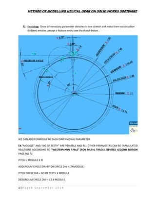
  • 1. METHOD OF MODELLING HELICAL GEAR ON SOLID WORKS SOFTWARE 1 | P a g e 4 S e p t e m b e r 2 0 1 4 1) First step: Draw all necessary parameter sketches in one stretch and make them construction (hidden) entities ,except a feature entity see the sketch below . WE CAN ADD FORMULAE TO EACH DIMENSIONAL PARAMETER EX:“MODULE” AND “NO OF TEETH” ARE VERIABLE AND ALL OTHER PARAMETERS CAN BE FARMULATED REALTIONS ACCORDING TO “WESTERMANN TABLE” (FOR METAL TRADE) ,REVISED SECOND EDITION PAGE NO 70 PITCH = MODULE X PI ADDENDUM CIRCLE DIA=PITCH CIRCLE DIA + (2XMODULE) PITCH CIRCLE DIA = NO OF TEETH X MODULE DEDUNDUM CIRCLE DIA = 1.2 X MODULE
  • 2. METHOD OF MODELLING HELICAL GEAR ON SOLID WORKS SOFTWARE 2 | P a g e 4 S e p t e m b e r 2 0 1 4 2) SECOND STEP: CALCULATION OF TEETH FROFILE TEETH THICKNESS DEPENDS ON CIRCULAR THICKNESS ANGLE =(( 360/NO OF TEETH)X0.5 )DRAW 2 HIDDEN LINES FROM THE CENTER OF SKETCH.
  • 3. METHOD OF MODELLING HELICAL GEAR ON SOLID WORKS SOFTWARE 3 | P a g e 4 S e p t e m b e r 2 0 1 4 DRAW TANGENT LINE “D” TO PITCH CIRCLE FORM INTERSECTION OF LINE “B” AND “PITCH CIRCLE” DRAW “E” 20* ANGLE LINE TO TANGENT LINE “D” FROM INTERSECTION OF LINE “B” AND PITCH CIRCLE DRAW CIRCLE “F” WHOSE DIA IS 1/4 OF PITCH CIRCLE DIA DRAW TANGENT CERCLE “G” TO LINE “E” (PREASSURE ANGLE LINE20DEG) DRAW CIRCLE “H” ,WHOSE CENTER IS AT (FROM INTERSECTION POINT “I” AND CIRCLE “G”) TO THE INTERSECTION POINT OF LINE “B” AND “PITCH CIRCLE DIA” THIS IS ABSOLUTELY A ANALYTICAL METHOD TO GET A FORM AND SHAPE 3) THIRD STEP:EXTRUDE DEDUNDUM TO REQUIRED HEIGHT AND ADD IT TO EQUATIONS IN SOLID WORKS KNOW ADDING PARAMETERS TO” EQUATIONS “ IN SOLID WORKS ,SO THAT ANY ONE CAN USE MY METHOD TO GET STANDERD HELICAL GEAR (YOU CAN MODIFY AT ANY POINT OF TIME IT IS LIKE A CEMENT ON IRON(IT WILL NEVER LEAVE RELATION).
  • 4. METHOD OF MODELLING HELICAL GEAR ON SOLID WORKS SOFTWARE 4 | P a g e 4 S e p t e m b e r 2 0 1 4 4) Fourth step: see the fig below in TOOLS menu we have “Equations) click on that you get Equations dialog box to add parameters and equations Before Adding Dimensional Parameters we can change the name of parameter ,so that we can easily identify particular parameter of a model in equations dialog box.See fig below. First pick the dimension, it changes color from black to green then click on more properties, dialog box appears .Hear in the Name Box We can add ADDENDUM .This will make easy to identify the particular parameters to Edit.
  • 5. METHOD OF MODELLING HELICAL GEAR ON SOLID WORKS SOFTWARE 5 | P a g e 4 S e p t e m b e r 2 0 1 4
  • 6. METHOD OF MODELLING HELICAL GEAR ON SOLID WORKS SOFTWARE 6 | P a g e 4 S e p t e m b e r 2 0 1 4 ADDENDUM is added to the Equations and we can Equate that parameter to the module and pitch circle as we have discussed earlier .in page 1
  • 7. METHOD OF MODELLING HELICAL GEAR ON SOLID WORKS SOFTWARE 7 | P a g e 4 S e p t e m b e r 2 0 1 4 Same way WE can add parameters of Features also see the fig. Double click on feature it will turn green and dimension of feature (eg : Extrude 6mm) Will appear in blue see fig below Just pick the dimension and change the name as thickness of gear In same way that will be added to the equations and we can relate it to module by formulae Eg: Thickness = 6 x Module See below fig go to “Tools” “Equations “pick feature dimension and “add “it will ask value .We can know add relation or equation by 2 methods Write equations by manually typing dimension name as in the “dimension property manager” Or we can pick other parameters (dimensional) to complete the equation. Like this we can add Equations of features and modify them at any point of time. Feature Dim
  • 8. METHOD OF MODELLING HELICAL GEAR ON SOLID WORKS SOFTWARE 8 | P a g e 4 S e p t e m b e r 2 0 1 4 5) FIFTH STEP: AFTER ADDING ALL PARAMETERS TO “EQUATIONS GETTING GEAR TEETH PROFILE Fig .BELOW SHOWS GEAR TOOTH PROFILE. A) DRAW ARC CONSTRAINED TO CIRCLE “H”. B) MIRROR IT BY LINE “A”. C) COMPLETE THE PROFILE USING ‘ADDENDUM” AND “DEDUNDUM” CIRCLES. D) SWEEP PROFILE WITH HELIX TO GET ONE TEETH. 6) SIXTH STEP: TO GET A HELIX ON PERIPHERY OF DEDUNDUM WE CAN USE FORMULAE LEAD = tan(helix angle) x π(dia of dedundum circle) WHERE HELIX ANGLE IS CONSTANT AND DEDUNDUM IS EQUATED BY FORMULAE TO CREATE HELIX OF LENGTH EQUAL TO GEAR THIKNESS ABOVE FAORMUALE IS USED. SEE BELOW fig. DEDENDUM ADDENDUM ARC
  • 9. METHOD OF MODELLING HELICAL GEAR ON SOLID WORKS SOFTWARE 9 | P a g e 4 S e p t e m b e r 2 0 1 4 a) Draw circle on face of dia equal to dedundum b) Use helix command (defined by height and pitch).see fig below c) In height 6mm(thickness of gear) will be equated d) In pitch the value 469.2703262 is equated by formulae (LEAD = tan(helix angle) x π(dia of dedundum circle) e) Start angle is 90◦ So we get helix profile like this.see equation table also.
  • 10. METHOD OF MODELLING HELICAL GEAR ON SOLID WORKS SOFTWARE 10 | P a g e 4 S e p t e m b e r 2 0 1 4 a) Lead is equated see below. b) Pressure angle is constant and value can be changed. c) See height of helix is equated to gear thickness d) Pressure angle can be changed e) Finally we can get helical gear which can be modified by varying only 4 parameters f) “ NO OF TEETH”,”MODULE””FILLET RADIOUS” AND ANY CONSTANT LIKE “HELIX ANGLE”
  • 11. METHOD OF MODELLING HELICAL GEAR ON SOLID WORKS SOFTWARE 11 | P a g e 4 S e p t e m b e r 2 0 1 4 Final product can be used for standard and unstandardized gear manufacturers like a changeable part. We can use this part in solid works “tool box” as a standard part (as they don’t have this at present). FINAL PRODUCT WILL LIIK LIKE THE FIG BELOW I think we can use this method for all parametric parts Thank you Regards Viinayak
  • 12. METHOD OF MODELLING HELICAL GEAR ON SOLID WORKS SOFTWARE 12 | P a g e 4 S e p t e m b e r 2 0 1 4 If product and concept is liked by companies or by www.solidworks.com I will be the happiest person. I will quote price money of 20000 $ for my small work. And method. We can add flanges and bores to gear. I will be happy to become a designer for any industry who requires this kind of work as I don’t have permanent job. I work at home Thanking you again
  • 13. METHOD OF MODELLING HELICAL GEAR ON SOLID WORKS SOFTWARE 13 | P a g e 4 S e p t e m b e r 2 0 1 4 For this work I have taken formulaes from “WESTERMANN TABLE” FOR METAL TRADE,REVISED SECOND EDITION.PAGE NO 70 ,112 AND 142 I THANK SOLIDWORKS SOFTAWARE GROUP I THANK WESTERMANN TABLE BOOK AND I THANK YOU FOR YOUR PRECIOUS TIME Thanking you Your’s faithfully Vinayak.B.Gudadari