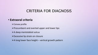
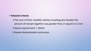
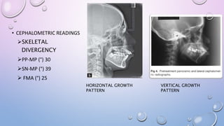
MAXIMUM ANCHORAGE
CONTROL
CRITERIA FOR DIAGNOSIS
• Extraoral criteria
Convex profile
Procumbent and everted upper and lower lips
A deep mentolabial sulcus
Excessive lip strain on closure
A long lower face height – vertical growth pattern
• Intraoral criteria
The sum of their maxillary dental crowding plus double the
amount of overjet together was greater than or equal to 11 mm
Space requirement > 10mm
Severe dentoalveolar protrusion
• CEPHALOMETRIC READINGS
SKELETAL
DIVERGENCY
PP-MP (°) 30
SN-MP (°) 39
 FMA (°) 25
VERTICAL GROWTH
PATTERN
HORIZONTAL GROWTH
PATTERN
MAXILLARY INCISOR ANGULATION
 mx1-na (mm) 23°, 7
mx1-sn (°) 104
mx1-pp (°) 110
PROCLINED
MAXILLARY INCISORS
MANDIBULAR INCISOR ANGULATION
md1-nb 34°, 10 mm
md1-apg (mm) 4
IMPA (°) 95
PROCLINED MANDIBULAR
INCISORS
BIOMECHANICS OF ANCHORAGE
• Angle’s stationary anchorage method was achieved by banding
multiple teeth to resist tipping.
• Charles tweed - a series of tip back bends to anchor the teeth like
a tent stakes to resist vertical and anteroposterior displacement during
intermaxillary elastic traction.
• P.R. Begg used tipback bends to maintain anteroposterior position of
anchorage teeth.
• All of these techniques are based on controlling the tooth movement type
ie translation vs tipping.
• The biomechanics of tooth movement is also based on discouraging tip of
anchor teeth and doing the reverse for active teeth
• A force system consists of applied force and moment at the
bracket and teeth move based on the nature of this force system and force
distribution about periodontium ( stress – strain relationship )
• The larger posterior moment preserve the anchorage as it resist tipping
• a large moment will cause distal crown tipping of posterior teeth causing
increase the size of extraction space.
• There are also vertical forces acting on anterior and posterior teeth
causing intrusive effects on anterior and extrusive effects on posterior
teeth.
ACTIVE AND REACTIVE MEMBER
• Orthodontic appliance can be considered to have active and reactive members.
• The active member is the part involved in tooth movement;
• The reactive member serves as anchorage and involves the teeth that will not
be displaced
MOMENT-TO-FORCE RATIO.
• To produce different types of tooth movement, the ratio between the applied
moment and the force on the crown must be changed
• As the M/F ratio is altered, the center of rotation changes.
• An active member must be capable of producing the desired moment and force.
• The m/f ratio is equally significant in the reactive member of the appliance.
• if the practitioner is considering preserving anchorage of the posterior segments
in an extraction case, to introduce a moment that tends to move roots forward
and crowns back is desirable so that, combined with the mesial forces acting on
the posterior segment, a more uniform distribution of stress is achieved in the
PDL
• The tip-back bend is one example in which a moment of this type is added to
the posterior segment to enhance anchorage.
HOW LOOP DESIGN AFFECTS THE M/F RATIOS
• A high M/F ratio is required to reinforce anchorage.
• Mechanical properties of closing loops depend on many factors, such as loop
height, width, shape, and position; wire material; cross-sectional dimensions;
and so on.
ALPHA MOMENT: This is the moment acting on the anterior teeth (often termed
anterior torque)
BETA MOMENT: Moment acting on the posterior teeth.
VERTICAL FORCES: These are intrusive-extrusive forces acting on the anterior or
posterior teeth. These forces generally result from unequal alpha and beta
moments.
• Differential anchorage is obtained by the application of unequal alpha and beta
moments.
• The higher moment is applied to the anchorage teeth.
• The differential moments are obtained by applying the concept of the off-centered
position.
• Opposite vertical forces of greater magnitude
• Greater moment on shorter arm.
By varying the magnitude of these moments, differential movement of the
posterior and anterior segments can be achieved. However, if the alpha and beta
moments are unequal, vertical forces are also generated.
 β > α
anchorage is enhanced by the mesial root moment of the posterior segment,
and there is a net intrusive force on the anterior teeth.
 α > β
anchorage of the anterior segment is increased, and there is a net extrusive
force on the anterior segment.
 α = β
If the alpha and beta moments are equal in magnitude, no vertical forces are
generated.
ANTERIOR RETRACTION
• The retraction loop should be placed closer to the canine than to the molar, and
a gable bend should be added near the molar.
• A gable bend that is larger in the posterior dimension will produce a larger beta
moment, thus increasing posterior anchorage.
• As the anterior teeth are retracted, it enhances posterior anchorage. Also, as the
beta moment becomes relatively greater, there is a greater intrusive force on
the anterior teeth and a greater extrusive forces on the posterior teeth.
LOAD-DEFLECTION RATE
• Is a factor in the delivery of a relatively constant force
• For active members a low load-deflection rate is desirable for two important reasons:
• (1) a mechanism with a low load-deflection rate maintains a more desirable stress level
in the PDL because the force on a tooth does not radically change magnitude every
time the tooth has been displaced
• (2) a member with a low load deflection rate offers greater accuracy in controlling force
magnitude
• The reactive member should be relatively rigid; that is, it should have a high
load-deflection rate.
• Equal and opposite forces produced by the active members usually are
distributed to localized areas, with just one or a few teeth involved. Localized
tooth changes in these areas can be minimized if the reactive members of the
appliance are sufficiently rigid.
MAXIMAL ELASTIC MOMENT
• Maximal elastic load or moment is the greatest force or moment
that can be applied to a member without causing permanent
deformation
• Active and reactive members must be designed so they do not
deform if activations are made that allow optimal force levels to be
reached.
• Both friction and frictionless mechanics offered intermittent manner
of force application having comparable magnitude and duration.
• There was no superiority of the frictionless over the friction
mechanics with regards to anchorage loss.
• Both direct and indirect mini-screw anchorage were efficient
methods to control the anchorage
FRICTION
• Orthodontist must apply added force to overcome friction, the result of which can
be increased anchorage loading and subsequent anchorage loss.
• Methods to reduce friction includes
• Wire should lie passively in the bracket slot before retraction is initiated
• Wire should be reduced in posterior segment to facilitate easier sliding
• By using self ligating brackets, there is a reduced friction between wire and holding
clip
• Highly polished stainless steel wires offer least friction on smooth surfaces in slots
of steel brackets
• Multiloop archwire can be used
FORCE LEVEL
• Forces should be calibrated properly during tooth movement
• According to Storey and smith (experiments on tooth movement response to
different pressure applications).
• Range of light pressures  teeth to move at an optimum rate  minimal
disturbance of the supportive tissues.
• Pressures below this range would produce a slow rate of response
• Those above  'undermining resorption  retarding tooth movement and cause
anchorage loss

max anchorage 2.pptx fdbghgrrgegreergrgger

  • 1.
  • 2.
    CRITERIA FOR DIAGNOSIS •Extraoral criteria Convex profile Procumbent and everted upper and lower lips A deep mentolabial sulcus Excessive lip strain on closure A long lower face height – vertical growth pattern
  • 3.
    • Intraoral criteria Thesum of their maxillary dental crowding plus double the amount of overjet together was greater than or equal to 11 mm Space requirement > 10mm Severe dentoalveolar protrusion
  • 4.
    • CEPHALOMETRIC READINGS SKELETAL DIVERGENCY PP-MP(°) 30 SN-MP (°) 39  FMA (°) 25 VERTICAL GROWTH PATTERN HORIZONTAL GROWTH PATTERN
  • 5.
    MAXILLARY INCISOR ANGULATION mx1-na (mm) 23°, 7 mx1-sn (°) 104 mx1-pp (°) 110 PROCLINED MAXILLARY INCISORS
  • 6.
    MANDIBULAR INCISOR ANGULATION md1-nb34°, 10 mm md1-apg (mm) 4 IMPA (°) 95 PROCLINED MANDIBULAR INCISORS
  • 7.
    BIOMECHANICS OF ANCHORAGE •Angle’s stationary anchorage method was achieved by banding multiple teeth to resist tipping. • Charles tweed - a series of tip back bends to anchor the teeth like a tent stakes to resist vertical and anteroposterior displacement during intermaxillary elastic traction. • P.R. Begg used tipback bends to maintain anteroposterior position of anchorage teeth.
  • 8.
    • All ofthese techniques are based on controlling the tooth movement type ie translation vs tipping. • The biomechanics of tooth movement is also based on discouraging tip of anchor teeth and doing the reverse for active teeth • A force system consists of applied force and moment at the bracket and teeth move based on the nature of this force system and force distribution about periodontium ( stress – strain relationship )
  • 9.
    • The largerposterior moment preserve the anchorage as it resist tipping • a large moment will cause distal crown tipping of posterior teeth causing increase the size of extraction space. • There are also vertical forces acting on anterior and posterior teeth causing intrusive effects on anterior and extrusive effects on posterior teeth.
  • 10.
    ACTIVE AND REACTIVEMEMBER • Orthodontic appliance can be considered to have active and reactive members. • The active member is the part involved in tooth movement; • The reactive member serves as anchorage and involves the teeth that will not be displaced
  • 11.
    MOMENT-TO-FORCE RATIO. • Toproduce different types of tooth movement, the ratio between the applied moment and the force on the crown must be changed • As the M/F ratio is altered, the center of rotation changes. • An active member must be capable of producing the desired moment and force. • The m/f ratio is equally significant in the reactive member of the appliance.
  • 12.
    • if thepractitioner is considering preserving anchorage of the posterior segments in an extraction case, to introduce a moment that tends to move roots forward and crowns back is desirable so that, combined with the mesial forces acting on the posterior segment, a more uniform distribution of stress is achieved in the PDL • The tip-back bend is one example in which a moment of this type is added to the posterior segment to enhance anchorage.
  • 14.
    HOW LOOP DESIGNAFFECTS THE M/F RATIOS • A high M/F ratio is required to reinforce anchorage. • Mechanical properties of closing loops depend on many factors, such as loop height, width, shape, and position; wire material; cross-sectional dimensions; and so on.
  • 15.
    ALPHA MOMENT: Thisis the moment acting on the anterior teeth (often termed anterior torque) BETA MOMENT: Moment acting on the posterior teeth. VERTICAL FORCES: These are intrusive-extrusive forces acting on the anterior or posterior teeth. These forces generally result from unequal alpha and beta moments.
  • 16.
    • Differential anchorageis obtained by the application of unequal alpha and beta moments. • The higher moment is applied to the anchorage teeth. • The differential moments are obtained by applying the concept of the off-centered position. • Opposite vertical forces of greater magnitude • Greater moment on shorter arm.
  • 17.
    By varying themagnitude of these moments, differential movement of the posterior and anterior segments can be achieved. However, if the alpha and beta moments are unequal, vertical forces are also generated.  β > α anchorage is enhanced by the mesial root moment of the posterior segment, and there is a net intrusive force on the anterior teeth.  α > β anchorage of the anterior segment is increased, and there is a net extrusive force on the anterior segment.  α = β If the alpha and beta moments are equal in magnitude, no vertical forces are generated.
  • 18.
    ANTERIOR RETRACTION • Theretraction loop should be placed closer to the canine than to the molar, and a gable bend should be added near the molar. • A gable bend that is larger in the posterior dimension will produce a larger beta moment, thus increasing posterior anchorage. • As the anterior teeth are retracted, it enhances posterior anchorage. Also, as the beta moment becomes relatively greater, there is a greater intrusive force on the anterior teeth and a greater extrusive forces on the posterior teeth.
  • 19.
    LOAD-DEFLECTION RATE • Isa factor in the delivery of a relatively constant force • For active members a low load-deflection rate is desirable for two important reasons: • (1) a mechanism with a low load-deflection rate maintains a more desirable stress level in the PDL because the force on a tooth does not radically change magnitude every time the tooth has been displaced • (2) a member with a low load deflection rate offers greater accuracy in controlling force magnitude
  • 20.
    • The reactivemember should be relatively rigid; that is, it should have a high load-deflection rate. • Equal and opposite forces produced by the active members usually are distributed to localized areas, with just one or a few teeth involved. Localized tooth changes in these areas can be minimized if the reactive members of the appliance are sufficiently rigid.
  • 21.
    MAXIMAL ELASTIC MOMENT •Maximal elastic load or moment is the greatest force or moment that can be applied to a member without causing permanent deformation • Active and reactive members must be designed so they do not deform if activations are made that allow optimal force levels to be reached.
  • 22.
    • Both frictionand frictionless mechanics offered intermittent manner of force application having comparable magnitude and duration. • There was no superiority of the frictionless over the friction mechanics with regards to anchorage loss. • Both direct and indirect mini-screw anchorage were efficient methods to control the anchorage
  • 23.
    FRICTION • Orthodontist mustapply added force to overcome friction, the result of which can be increased anchorage loading and subsequent anchorage loss. • Methods to reduce friction includes • Wire should lie passively in the bracket slot before retraction is initiated • Wire should be reduced in posterior segment to facilitate easier sliding • By using self ligating brackets, there is a reduced friction between wire and holding clip • Highly polished stainless steel wires offer least friction on smooth surfaces in slots of steel brackets • Multiloop archwire can be used
  • 24.
    FORCE LEVEL • Forcesshould be calibrated properly during tooth movement • According to Storey and smith (experiments on tooth movement response to different pressure applications). • Range of light pressures  teeth to move at an optimum rate  minimal disturbance of the supportive tissues. • Pressures below this range would produce a slow rate of response • Those above  'undermining resorption  retarding tooth movement and cause anchorage loss