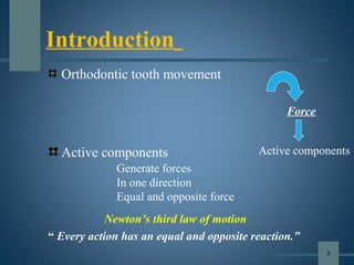
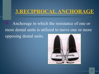
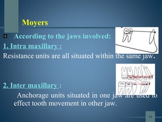
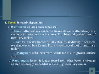
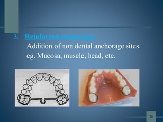
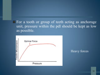
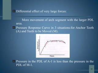
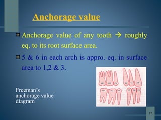
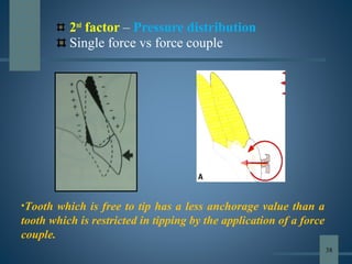
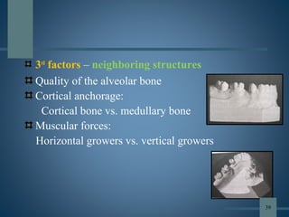
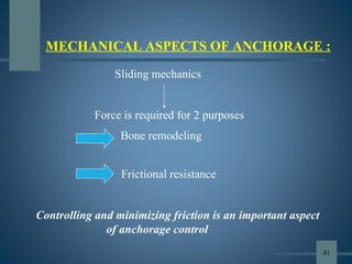
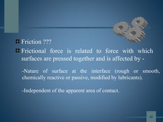
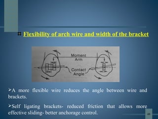
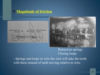
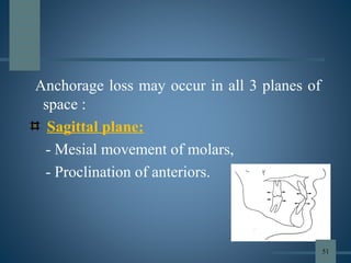
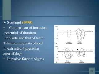
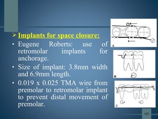
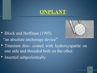
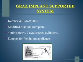
This document discusses various aspects of orthodontic anchorage. It defines anchorage and provides classifications including according to the manner of force application, the jaws involved, and the site of anchorage. Biological aspects are covered such as factors affecting an individual tooth's anchorage value like the number, shape, and length of roots. Mechanical aspects include using force couples to restrict unwanted tooth movement. Different anchorage reinforcement techniques are presented such as extraoral appliances, implants, and temporary anchorage devices.


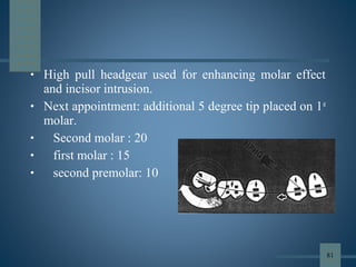
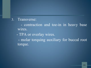

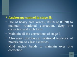


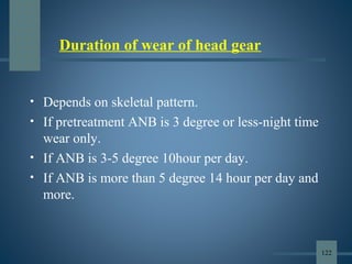
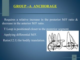
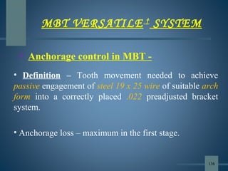
![ Before 1986, only brackets with
vertical slots, such as ribbon arch
appliances, could be used to produce
differential tooth movement. Precise
mesiodistal angular control was
lacking, and the vertical slots hindered
archwire placement, allowing
excessive tipping during retraction and
making finishing difficult.
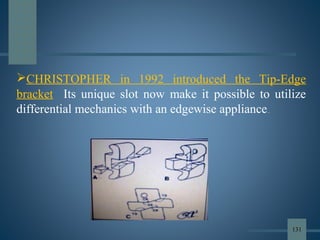
DIFFERENTIAL STRAIGHT ARCH
TECHNIQUE
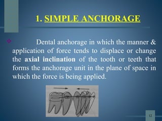
[TIP EDGE BRACKETS]
ANCHORAGE IN FIXED APPLIANCES:
130](https://image.slidesharecdn.com/anchorageinorthodonticsppt-190701161901/85/Anchorage-in-orthodontics-ppt-130-320.jpg)

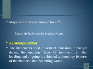


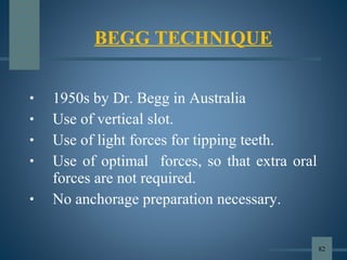
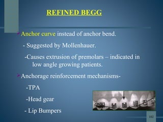
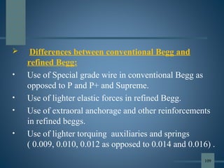
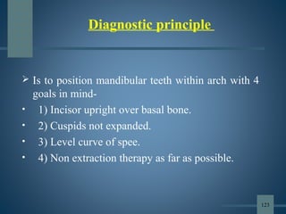
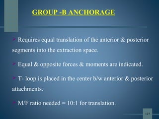
![• The conventional methods of reinforcing anchorage are less
than ideal, because they either rely on structures that are
themselves potentially mobile [teeth] or they rely too heavily
on patient compliance [ HG & Elastics].
• Skeletal anchorage overcomes many of these shortcomings.
• Boucher: Implants are alloplastic devices which are
surgically inserted into or onto jaw bone.
SKELETAL ANCHORAGE
154](https://image.slidesharecdn.com/anchorageinorthodonticsppt-190701161901/85/Anchorage-in-orthodontics-ppt-154-320.jpg)


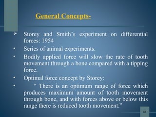
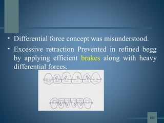
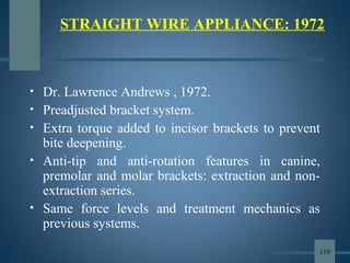
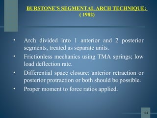
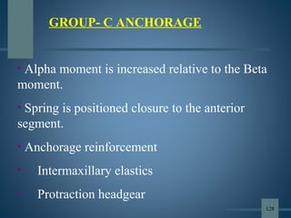
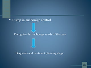
![3) Plate designs
- Skeletal anchorage system [SAS]
- Graz implant supported system
- Zygoma anchorage system
BASED ON AREA OF PLACEMENT
- Subperiosteal implants
- Osseous implants
- Inter dental implants 165](https://image.slidesharecdn.com/anchorageinorthodonticsppt-190701161901/85/Anchorage-in-orthodontics-ppt-165-320.jpg)


![lecture_05_and_06-Anchorage_in_orthodontics[1].pptx](https://cdn.slidesharecdn.com/ss_thumbnails/lecture05and06-anchorageinorthodontics1-240224004209-047377b5-thumbnail.jpg?width=640&height=640&fit=bounds)


