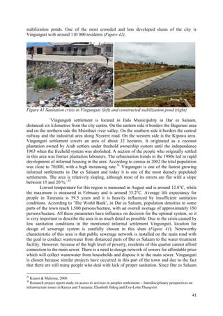
This document is a master's thesis submitted by Dario Marić that examines the optimization of hydrotechnical systems. Specifically, it aims to determine the optimal configuration and physical parameters of a new hydrotechnical system using optimization synthesis methods. The thesis provides background information on hydrotechnical systems and their history, discusses various types of water sewage systems, and describes the design process for sewer systems with a case study of optimizing a simplified sewer system in Dar es Salaam, Tanzania.


![68
6. LITERATURE
[1] Bakalian Alexander, Wright Albert, Otis Richard, Netto de Azevedo Jose: Simplified
Sewerage: Design Guidelines
[2] Duncan Mara: PC-based Simplified Sewer Design
[3] Margeta J.: Kanalizacija naselja, Građevinski fakultet Split, 1998.
[4] Petri D. Juuti, Tapio S. Katko, Heikki S. Vuorinen : Environmental History of Water -
Global views on community water supply and sanitation
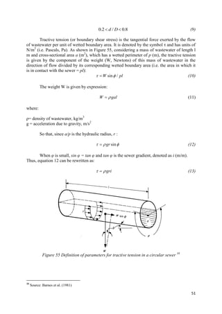
[5] Tušar Božena, Pročišćavanje otpadnih voda; Kigen d.o.o.; Zagreb, 2009
[6] UN-HABITAT; Tanzania: DAR ES SALAAM CITY PROFILE, 2009
[7] Conception and Installation of the Condominial Sewerage System in the town of Santa
Maria – Case study
[8] Elisabeth Ilskog and Eva-Lotta Thunqvist : Research project report study on access to
services in peoples settlements – Interdisciplinary perspectives on infrastructure issues in
Kenya and Tanzania
[9] Hidrotehnički sustavi, lessons; Marija Šperac, Faculty of Civil Engineering Osijek
[10] Hidrotehnički sustavi, lessons- Faculty of Civil Engineering Zagreb
[11] Rural water demand: The case of Eastern Africa – Lessons from the Drawers of Water II
study
[12] Strengthening the capacity of water utilities to deliver water and sanitation services,
environmental health and hygiene education to low income urban communities: Dar es
Salaam Water and Sewerage Authority - Engr. Bill Wandera
[13] Triche Thelma: Public-private and public-public partnerships in water supply and
sewerage services in Dar es Salaam; Case study
[14] http://water.worldbank.org/shw-resource-guide/infrastructure/menu-technical-
options/open-drains (14.05.2016.)
[15] http://e-gfos.gfos.hr/index.php/arhiva/broj-2/rjesenje-kanalizacije-naselja (18.04.2016.)
[16] http://www.pseau.org/sites/default/files/fichiers/r_d/non-
convetional_sewers_analysis_report.pdf (18.04.2016.)
[17] http://www.humanitariancentre.org/2013/11/opinion-simplified-sewerage-and-africas-
sanitation-crisis/ (10.06.2016.)
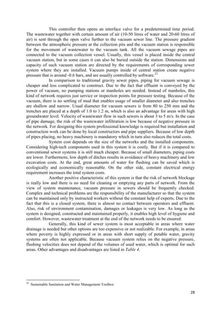
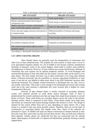
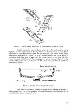
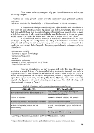
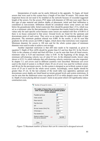
[18] https://cadmapper.com/ (28.05.2016.)](https://image.slidesharecdn.com/f6a7be7c-a1f8-4f33-b672-a1562bdd16b3-161225195908/85/MasterThesis_DarioMaric_final-73-320.jpg)
![69
[19] https://www.cam.ac.uk/news/cambridge-students-launch-development-initiative-in-dar-
es-salaam (24.06.2016.)
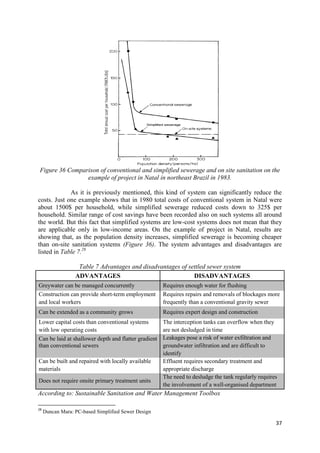
[20] http://dawasa.go.tz/facilities/sewerage-system/ (24.05.2016.)
[21] https://en.wikipedia.org/wiki/History_of_water_supply_and_sanitation (21.04.2016.)
[22] http://water.worldbank.org/shw-resource-guide/infrastructure/menu-technical-
options/open-drains (17.05.2016.)
[23] http://www.sswm.info/ (13.05.2016.)
[24] http://pubs.usgs.gov/chapter11/chapter11C.html (11.07.2016.)
[25] http://www.newworldencyclopedia.org/entry/Sewage (19.04.2016.)
[26] https://cambridgedevelopment.wordpress.com/category/engineering/ (19.07.2016.)](https://image.slidesharecdn.com/f6a7be7c-a1f8-4f33-b672-a1562bdd16b3-161225195908/85/MasterThesis_DarioMaric_final-74-320.jpg)