
Recommended
More Related Content
What's hot
What's hot (15)
Similar to Manuscript_Roll Track
Similar to Manuscript_Roll Track (14)
Manuscript_Roll Track
- 1. Reliability Centered Maintenance of Segment Rolls in Thin Slab Continuous Caster through ROLL TRACK TM Software Sandeep S Teredesai, Atanu Kumar Borkotoky, Pradip K Patra, Prakash Sappa, Satya Prakash (Sandeep.Teredesai@jsw.in, Atanu.Borkotoky@jsw.in, Pradip.Patra@jsw.in, Prakash.Sappa@jsw.in, Satya.Prakash@jsw.in) JSW Steel Limited, Geetapuram, Dolvi, Tal - Pen, Dist- Raigad - 402107, Maharashtra, INDIA Tel: +91-2143-277501 to 277515, Fax: +91-2143-277820 Website: www.jsw.com Abstract: Vertical Thin Slab Continuous Caster Machine is the state-of-art technology in today‟s steel making industries. Advanced Compact Strip Process (CSP) casters are designed for larger casting length, higher casting speed with compact equipments like segments. Ispat Industries Limited has two casting strands, of which one is equipped with Liquid Core Reduction (LCR) Technology. Segments of both casters have more than 350 rolls and 700 bearings running in machine at any point of time. Besides this, there are more than 1200 rollers and 2400 bearings being installed in standby set of segments. Aforesaid figures signify the importance of having a good roll maintenance management system for more than 1500 rolls and 3000 bearings which are transiting from machine to repair area. Unhampered caster productivity and product quality largely necessitates reliable roll performance with longer stay of segments in machine. Ispat has developed in-house unique software “Roll Track”, with help of which, it is now possible for the segment repair shop personnel to track the life and as-on- time status of each and every bearing and roll of the entire set of 27 segments. The software referred facilitates proactive approach to segment maintenance planning. This, in turn, reduces unplanned machine stoppages or breakdowns due to roll jam or bearing failures which generally lead to segment change in machines, thereby causing losses in productivity as well as losses due to heavy inventory. INTRODUCTION Slab leaving from mould is entered in segments wherein the hot stand is provided the support through rollers. More than 8 types of rolls of various size in single & double split design are installed in 27 segments. The total quantity of rollers & bearings installed in two casting strands are 350 and 700 respectively. There are 3 such sets are in use wherein more than 1000 rolls & 2000 bearings are installed. Besides this more than 500 rolls are in spare for circulation. Movement of such large amount of rollers and bearings in to different segments, various positions, re-welding & repair necessiates a good Roll Maintenance Management Sytem in Segment Repair Shop. Every single roll being mounted in segment during repair should be reliable to deliver preset campaign life to avaoid unplannned stoppages in caster on account of roll failure. Segment Maintenance Practice Conventional Method of Segment Maint. Like any casters; in ISPAT Segment change from casting machine is based on the number of heats cast. According to the segment type & its position in machine, a SOP is formulated indicating the change of segment based on the number of heats cast since last installation in casting machine. However achievement of SOP life shall be supported by defect free final product quality. At times the product quality is affected by the defects like Scratch Marks, Deep Grooves etc. arise out of caster which more often than other related to failure of segment rollers. Segment removed from casting machine is dismantled for either of following reasons
- 2. 1. General lubrication testing 2. Replacement of failed rolls if any and 3. Re-alignment of roller table 1.1 Lubrication Test: Segment roller bearings are having grease lubrication system through dual line grease manifold blocks ( Grease Distributors ). During this testing movement of block metering pins is checked, stroke setting is done or replacement of faulty block is done to ensure proper lubrication to each bearing. 2.1 Replacement of Failed Rollers: Roll failure is largely attributed to bearing failure resulting jamming of roll. Such jam rolls were replaced by preassembled rolls. 3.1 Re-alignment of rolls: Exposure to constant heat & rolling as slab gets extracted leads to wear of rolls. Uneven roll wear is common; upsetting slab profile and if not corrected may leads to bulging. Realignment of rollers is carried out with precision templates to ensure correct roll gap in each segment. This conventional cycle was in practice since last more than 10 years which shown following major disadvanges over the period of time. Disadvantages: 1) Increase in unplanned stoppages of casting machine for segment change 2) Unpredictable failure of segment rolls. 3) Reduced campaign life & reliability of segment 4) Poor performance 5) Increase overall workload due to frequent re-work on segment 6) Increase in Inventories of rolls, bearings and other associated parts However the above disadvantages is offset with marginal improvement in segment performance by implementing periodical revamping of segments but consistency in performance is not achieved. The conventional method apparently shows advantages such as low maintenance cost and less manpower but if looked closely it has shown many disadvantages over the period of time; incurring high losses not only towards productivity but also in monitory terms. To defy on aforesaid disadvantages ISPAT has developed software ROLL TARCK TM which completely redefined the conventional segment roll maintenance practice to Reliability Centered Segment Maintenance Practice in cost effective manner.
- 3. New RCM Method with ROLL TRACK It is strongly felt that the tracking the segment performance ( Life in heats ) and its scheduled revamping is not just enough as it shows improvement in a particular segment for short time but leads to increase maintenance cost significantly. Roll Track System provides unique way to keep tracking of every individual bearing along with roll & its assembly. It facilitates approach of Proactive & Predictive Maintenance rather than Preventive Maintenance among the thousands of roll & bearing running in 27 segments. The each roll, every bearing & their assembly is provided unique Track ID against which its performance, current location, life achieved, PM and RCA data etc is recorded in system. This information is available on line for analysis, decision making & help to focus on maintenance of a particular roll than entire 40 rolls when the segment is removed for routine maintenance. A figure_____ below is Roll Mapping Screen shows as-on-time status of installed bearing & rolls in segment no 3-2. Roll No 3 & 4 is highlighted indicating that the bearings of Roll No. CR157510156 and CL158210155 need inspection. Similarly „A‟ side bearing ( Yellow Colour ) of roll no. CR157510364 need to be inspected whereas „B‟ side bearing ( Red Colour ) need to be changed. It also shows no. of heats cast since last PM giving one step view for comparison between various segments. The roll arrangement is Single Split defined as Type-1 and two rolls forming an assembly is identified separately with Roll ID. Ex – CL158210325 (Ref. Nomenclature details in Fig_____) Bearing is due for Inspection Bearing Due for Replacement Bearing is OK
- 4. Like roll, every bearing is also identified with a unique logical ID. This logical ID provides information about the roll or bearing against which its performance & repair history is recorded starting from its receipt in stores to discard / scrap. Fig_____ shows information about a roll which is presently in assembled condition and ready in spare for replacement. The other information like mounted bearings ID & its life, assembly number, vendor detail, heats after last machining, present diameter any many other is fetch from database when required. Further, history records of last change as well as overhauling is also displayed in subsequent tabs below current details.
- 5. A pair of roll after mounting the bearing is assembled together and each such assembly is also identified with incremental assembly number for its type to locate the parts fit in. Software generate alarms referring to SOP guiding engineers to plan segment maintenance activities, make preassembled rollers ready for installation in advance. Another in-house developed software APPIM helps to optimize the inventory levels for more than 113 items pertaining to roll maintenance area. New system focus on Proactive Maintenance of every roll prioritized by software based on its performance and this information is available in MIS reports. Fig. _____ shows the roll change frequency with respect to each segment for desired duration. The report also shows comparison between different segments in view of heats cast, number of times it is changed from caster and numbers of rolls changed during the desired period. The tabulated data when is plotted gives the trend of roll failure for any segment which is further analyzed w.r.t. position of roll, diameter, bearing life etc.
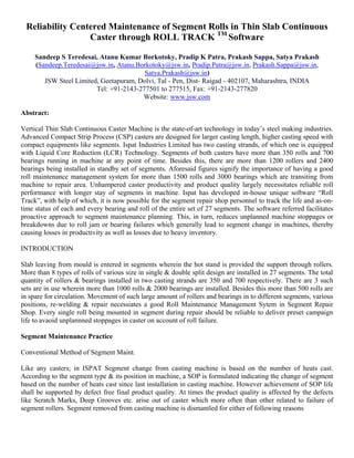
- 6. Conclusion: The following results are achieved. The highest ever campaign life is achieved 705 heats ( 1.33 MT ) with a single roll failure