Magnetic
Properties
G I VE N BY :
ANUJA SOLANKI (2301CB06)
KHUSHI YADAV (2301MC11)
ADITYA THURWAL (2302MT01)
JATIN AGARWAL (2301ME23)
PIYUSH JATOLIYA (2301ME37)
2.
Introduction
Magnetism, the phenomenonby which materials assert an
attractive or repulsive force or influence on other materials, has
been known for thousands of years.
However, the underlying principles and mechanisms that explain
the magnetic phenomenon are complex and subtle , until
relatively recent times.
Many of our modern technological devices rely on magnetism
and magnetic materials; these include electrical power
generators and transformers, electric motors, radio, television,
telephones, computers, and components of sound and video
reproduction systems.
Iron, some steels, and the naturally occurring mineral lodestone
are well-known examples of materials that exhibit magnetic
properties.
Not so familiar, however, is the fact that all substances are
influenced to one degree or another by the presence of a
magnetic field.
3.
Magnetic dipoles
Magnetic forcesare generated by moving electrically
charged particles; these magnetic forces are in addition to
any electrostatic forces that may prevail.
Many times it is convenient to think of magnetic forces in
terms of fields.
Imaginary lines of force may be drawn to indicate the
direction of the force at positions in the vicinity of the field
source.
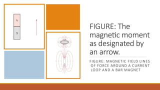
The magnetic field distributions as indicated by lines of force
are shown for a current loop and also a bar magnet in
Figure.
4.
FIGURE: The
magnetic moment
asdesignated by
an arrow.
FIGURE: MAGNETIC FIELD LINES
OF FORCE AROUND A CURRENT
LOOP AND A BAR MAGNET
5.
Magnetic dipoles arefound to exist in magnetic materials, which, in some
respects, are analogous to electric dipoles.
Magnetic dipoles may be thought of as small bar magnets composed of
north and south poles instead of positive and negative electric charges.
Magnetic dipole moments are represented by arrows, as shown in Figure.
Magnetic dipoles are influenced by magnetic fields in a manner similar to
the way in which electric dipoles are affected by electric fields.
Within a magnetic field, the force of the field itself exerts a torque that
tends to orient the dipoles with the field.
A familiar example is the way in which a magnetic compass needle lines up
with the Earth’s magnetic field
6.
DIAMAGNETISM
AND
PARAMAGNETISM
Diamagnetism is avery weak form of
magnetism that is nonpermanent and
persists only while an external field is being
applied.
It is induced by a change in the orbital
motion of electrons due to an applied
magnetic field.
The magnitude of the induced magnetic
moment is extremely small, and in a
direction opposite to that of the applied
field. Thus, the relative permeability μr is
less than unity (however, only very slightly),
and the magnetic susceptibility is negative;
that is, the magnitude of the B field within a
diamagnetic solid is less than that in a
vacuum.
7.
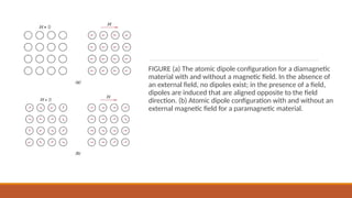
FIGURE (a) Theatomic dipole configuration for a diamagnetic
material with and without a magnetic field. In the absence of
an external field, no dipoles exist; in the presence of a field,
dipoles are induced that are aligned opposite to the field
direction. (b) Atomic dipole configuration with and without an
external magnetic field for a paramagnetic material.
8.
The volume susceptibilityXm for diamagnetic solid materials is on the
order of -10-5. When placed between the poles of a strong
electromagnet, diamagnetic materials are attracted toward regions
where the field is weak.
Figure a illustrates schematically the atomic magnetic dipole
configurations for a diamagnetic material with and without an external
field; here, the arrows represent atomic dipole moments, like for the
preceding discussion, arrows denoted only electron moments.
Diamagnetism is found in all materials; but because it is so weak, it can
be observed only when other types of magnetism are totally absent.
This form of magnetism is of no practical importance.
9.
For some solidmaterials, each atom possesses a permanent dipole moment by virtue of incomplete cancellation of
electron spin and/or orbital magnetic moments.
In the absence of an external magnetic field, the orientations of these atomic magnetic moments are random, such that
a piece of material possesses no net macroscopic magnetization. These atomic dipoles are free to rotate, and
paramagnetism results when they preferentially align, by rotation, with an external field as shown in Figure b.
These magnetic dipoles are acted on individually with no mutual interaction between adjacent dipoles. Inasmuch as the
dipoles align with the external field, they enhance it, giving rise to a relative permeability μr that is greater than unity,
and to a relatively small but positive magnetic susceptibility.
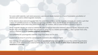
Susceptibilities for paramagnetic materials range from about 10-5 to 10-2.
A schematic B-versus-H curve for a paramagnetic material is also shown in Figure.
Both diamagnetic and paramagnetic materials are considered to be nonmagnetic because they exhibit magnetization
only when in the presence of an external field. Also, for both, the flux density B within them is almost the same as it
would be in a vacuum.
10.
FIGURE: Schematic representation
ofthe flux density B versus the
magnetic field strength H for
diamagnetic, paramagnetic, and
ferromagnetic materials
11.
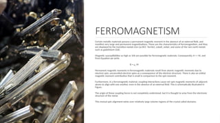
FERROMAGNETISM
Certain metallic materialspossess a permanent magnetic moment in the absence of an external field, and
manifest very large and permanent magnetizations. These are the characteristics of ferromagnetism, and they
are displayed by the transition metals iron (as BCC ferrite), cobalt, nickel, and some of the rare earth metals
such as gadolinium (Gd).
Magnetic susceptibilities as high as 106 are possible for ferromagnetic materials. Consequently, H << M, and
from Equation we write
B = μo M
Permanent magnetic moments in ferromagnetic materials result from atomic magnetic moments due to
electron spin; uncancelled electron spins as a consequence of the electron structure. There is also an orbital
magnetic moment contribution that is small in comparison to the spin moment.
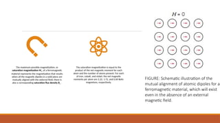
Furthermore, in a ferromagnetic material, coupling interactions cause net spin magnetic moments of adjacent
atoms to align with one another, even in the absence of an external field. This is schematically illustrated in
Figure.
The origin of these coupling forces is not completely understood, but it is thought to arise from the electronic
structure of the metal.
This mutual spin alignment exists over relatively large volume regions of the crystal called domains.
12.
The maximum possiblemagnetization, or
saturation magnetization Ms ,of a ferromagnetic
material represents the magnetization that results
when all the magnetic dipoles in a solid piece are
mutually aligned with the external field; there is
also a corresponding saturation flux density Bs .
The saturation magnetization is equal to the
product of the net magnetic moment for each
atom and the number of atoms present. For each
of iron, cobalt, and nickel, the net magnetic
moments per atom are 2.22, 1.72, and 0.60 Bohr
magnetons, respectively.
FIGURE: Schematic illustration of the
mutual alignment of atomic dipoles for a
ferromagnetic material, which will exist
even in the absence of an external
magnetic field.
13.
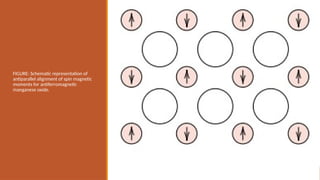
ANTIFERROMAGNETISM
This phenomenon ofmagnetic moment coupling between adjacent atoms or ions occurs in materials other
than those that are ferromagnetic.
In one such group, this coupling results in an antiparallel alignment; the alignment of the spin moments of
neighboring atoms or ions in exactly opposite directions is termed antiferromagnetism.
Manganese oxide (MnO) is one material that displays this behavior. Manganese oxide is a ceramic material
that is ionic in character, having both Mn+2 and O-2 ions. No net magnetic moment is associated with the O-2
ions, since there is a total cancellation of both spin and orbital moments.
However, the Mn+2 ions possess a net magnetic moment that is predominantly of spin origin.
These Mn+2 ions are arrayed in the crystal structure such that the moments of adjacent ions are antiparallel.
This arrangement is represented schematically in Figure. Obviously, the opposing magnetic moments cancel
one another, and, as a consequence, the solid as a whole possesses no net magnetic moment.
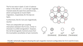
FERRIMAGNETISM
Some ceramics alsoexhibit a permanent magnetization, termed
ferrimagnetism.
The macroscopic magnetic characteristics of ferromagnets and
ferrimagnets are similar; the distinction lies in the source of the
net magnetic moments.
The principles of ferrimagnetism are illustrated with the cubic
ferrites.
These ionic materials may be represented by the chemical
formula MFe2O4 , in which M represents any one of several
metallic elements.
The prototype ferrite is Fe3O4 , the mineral magnetite,
sometimes called lodestone.
16.
FIGURE: Schematic diagramshowing the spin magnetic moment configuration for Fe+2 and Fe+3 ions
in Fe3O4 .
The Fe ions exist in both +2 and +3 valence
states in the ratio of 1 : 2. A net spin magnetic
moment exists for each Fe+2 and Fe+3 ion,
which corresponds to 4 and 5 Bohr
magnetons, respectively, for the two ion
types.
Furthermore, the O-2 ions are magnetically
neutral.
There are antiparallel spin-coupling
interactions between the Fe ions, similar in
character to antiferromagnetism. However,
the net ferromagnetic moment arises from
the incomplete cancellation of spin moments.
17.
DOMAINS AND
HYSTERESIS
Any ferromagneticor ferrimagnetic material that is at a temperature below Tc is composed of
small-volume regions in which there is a mutual alignment in the same direction of all
magnetic dipole moments, as illustrated in Figure a.
Such a region is called a domain, and each one is magnetized to its saturation magnetization.
Adjacent domains are separated by domain boundaries or walls, across which the direction
of magnetization gradually changes (Figure b).
Normally, domains are microscopic in size, and for a polycrystalline specimen, each grain may
consist of more than a single domain. Thus, in a macroscopic piece of material, there will be a
large number of domains, and all may have different magnetization orientations.
The magnitude of the M field for the entire solid is the vector sum of the magnetizations of all
the domains, each domain contribution being weighted by its volume fraction.
For an unmagnetized specimen, the appropriately weighted vector sum of the magnetizations
of all the domains is zero.
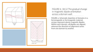
18.
FIGURE b: 18.12The gradual change
in magnetic dipole orientation
across a domain wall.
FIGURE a: Schematic depiction of domains in a
ferromagnetic or ferrimagnetic material;
arrows represent atomic magnetic dipoles.
Within each domain, all dipoles are aligned,
whereas the direction of alignment varies
from one domain to another.
19.
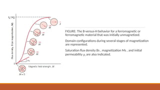
Flux density Band field intensity H are not proportional for ferromagnets and
ferrimagnets.
If the material is initially unmagnetized, then B varies as a function of H as shown in
Figure.
The curve begins at the origin, and as H is increased he B field begins to increase
slowly, then more rapidly, finally leveling off and becoming independent of H.
This maximum value of B is the saturation flux density Bs , and the corresponding
magnetization is the saturation magnetization Ms , mentioned previously.
Since the permeability is the slope of the B-versus-H curve, it may be noted from
Figure that the permeability changes with and is dependent on H.
On occasion, the slope of the B-versus-H curve at H = 0 is specified as a material
property, which is termed the initial permeability μi , as indicated in Figure.
20.
FIGURE: The B-versus-Hbehavior for a ferromagnetic or
ferromagnetic material that was initially unmagnetized.
Domain configurations during several stages of magnetization
are represented.
Saturation flux density Bs , magnetization Ms , and initial
permeability μi are also indicated.
21.
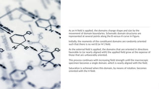
As an Hfield is applied, the domains change shape and size by the
movement of domain boundaries. Schematic domain structures are
represented at several points along the B-versus-H curve in Figure.
Initially, the moments of the constituent domains are randomly oriented
such that there is no net B (or M ) field.
As the external field is applied, the domains that are oriented in directions
favorable to (or nearly aligned with) the applied field grow at the expense of
those that are unfavorably oriented.
This process continues with increasing field strength until the macroscopic
specimen becomes a single domain, which is nearly aligned with the field.
Saturation is achieved when this domain, by means of rotation, becomes
oriented with the H field.