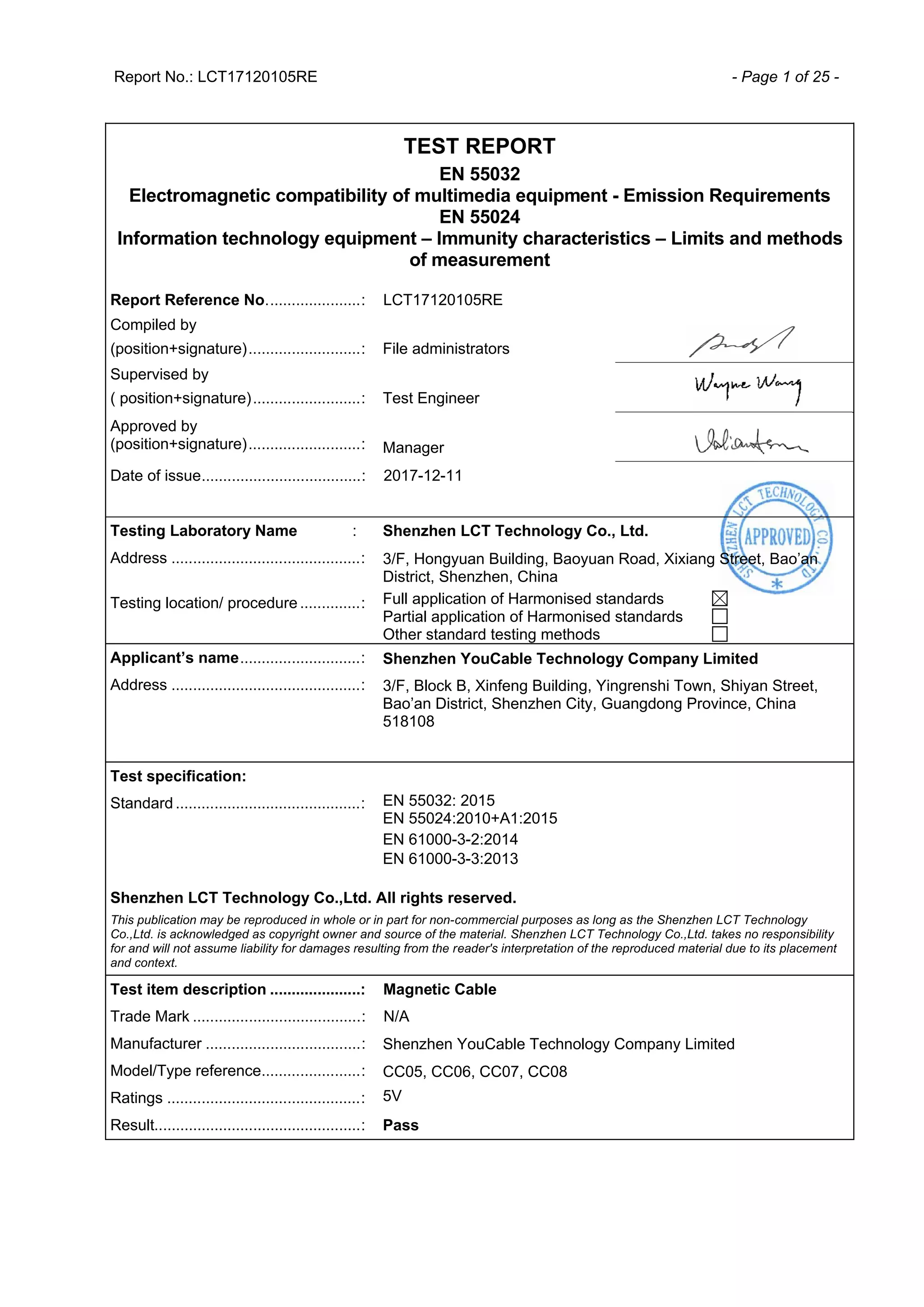
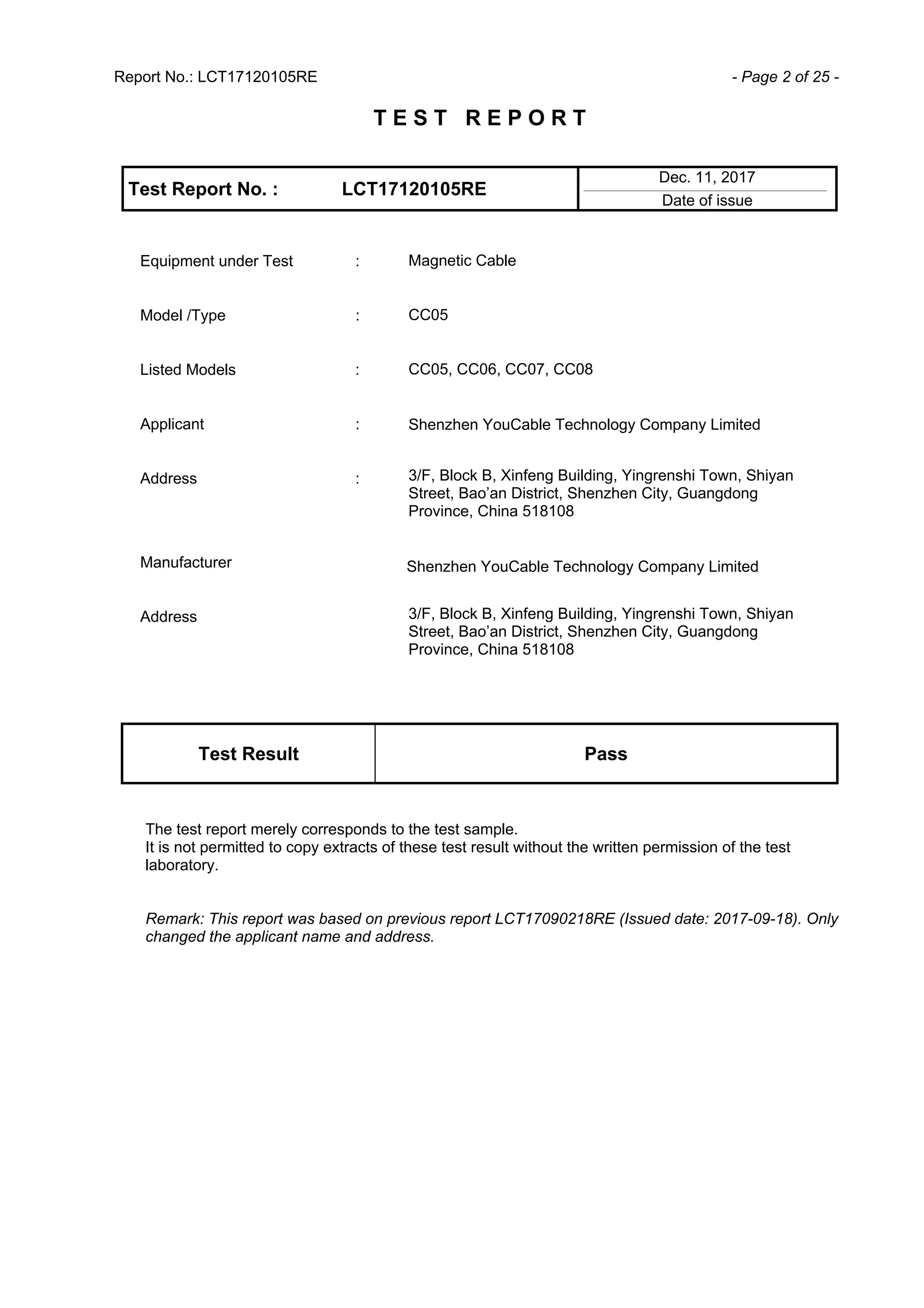
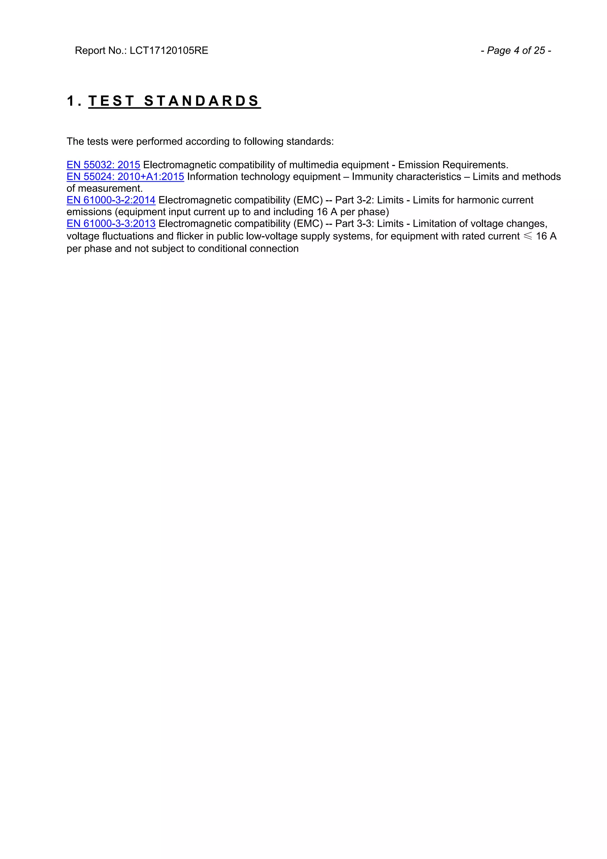
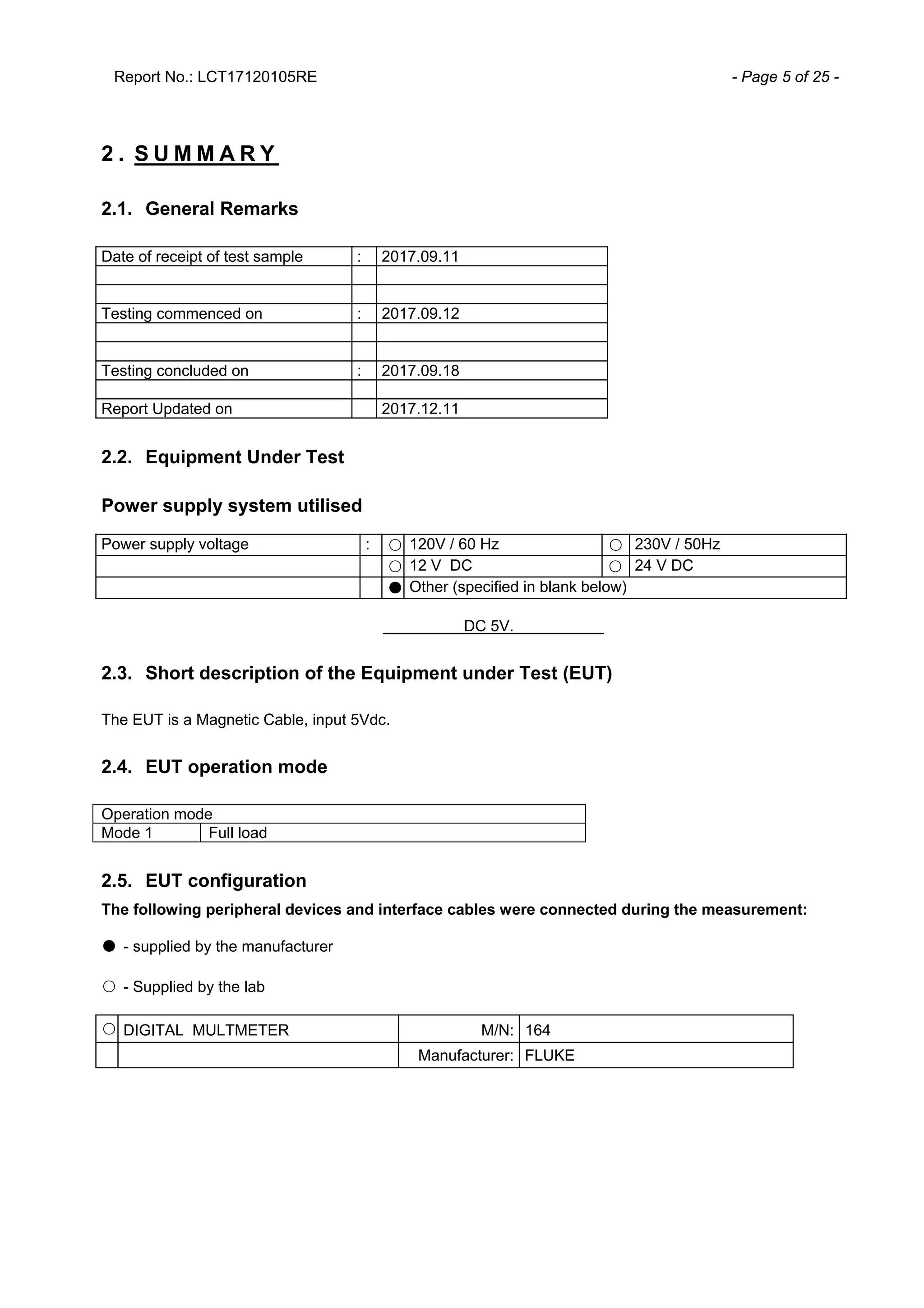
Report No.: LCT17120105RE - Page 1 of 25 -
TEST REPORT
EN 55032
Electromagnetic compatibility of multimedia equipment - Emission Requirements
EN 55024
Information technology equipment – Immunity characteristics – Limits and methods
of measurement
Report Reference No......................: LCT17120105RE
Compiled by
(position+signature)..........................: File administrators
Supervised by
( position+signature).........................: Test Engineer
Approved by
(position+signature)..........................: Manager
Date of issue.....................................: 2017-12-11
Testing Laboratory Name : Shenzhen LCT Technology Co., Ltd.
Address ............................................: 3/F, Hongyuan Building, Baoyuan Road, Xixiang Street, Bao’an
District, Shenzhen, China
Testing location/ procedure ..............: Full application of Harmonised standards
Partial application of Harmonised standards
Other standard testing methods
Applicant’s name............................: Shenzhen YouCable Technology Company Limited
Address ............................................: 3/F, Block B, Xinfeng Building, Yingrenshi Town, Shiyan Street,
Bao’an District, Shenzhen City, Guangdong Province, China
518108
Test specification:
Standard ...........................................: EN 55032: 2015
EN 55024:2010+A1:2015
EN 61000-3-2:2014
EN 61000-3-3:2013
Shenzhen LCT Technology Co.,Ltd. All rights reserved.
This publication may be reproduced in whole or in part for non-commercial purposes as long as the Shenzhen LCT Technology
Co.,Ltd. is acknowledged as copyright owner and source of the material. Shenzhen LCT Technology Co.,Ltd. takes no responsibility
for and will not assume liability for damages resulting from the reader's interpretation of the reproduced material due to its placement
and context.
Test item description .....................: Magnetic Cable
Trade Mark .......................................: N/A
Manufacturer ....................................: Shenzhen YouCable Technology Company Limited
Model/Type reference.......................: CC05, CC06, CC07, CC08
Ratings .............................................: 5V
Result................................................: Pass
Report No.: LCT17120105RE - Page 2 of 25 -
T E S T R E P O R T
Test Report No. : LCT17120105RE
Dec. 11, 2017______________________________________________________________________________________________
Date of issue
Equipment under Test : Magnetic Cable
Model /Type : CC05
Listed Models : CC05, CC06, CC07, CC08
Applicant : Shenzhen YouCable Technology Company Limited
Shenzhen YouCable Technology Company Limited
Address : 3/F, Block B, Xinfeng Building, Yingrenshi Town, Shiyan
Street, Bao’an District, Shenzhen City, Guangdong
Province, China 518108
3/F, Block B, Xinfeng Building, Yingrenshi Town, Shiyan
Street, Bao’an District, Shenzhen City, Guangdong
Province, China 518108
Manufacturer
Address
Test Result Pass
The test report merely corresponds to the test sample.
It is not permitted to copy extracts of these test result without the written permission of the test
laboratory.
Remark: This report was based on previous report LCT17090218RE (Issued date: 2017-09-18). Only
changed the applicant name and address.
Report No.: LCT17120105RE - Page 3 of 25 -
Contents
1 .   T E S T S T A N D A R D S · · · · · · · · · · · · · · · · · · · · · · · · · · · · · · · · · · · · · · · · · · · · · · · · · · · · · · · · · · · 4  
2 .   S U M M A R Y · · · · · · · · · · · · · · · · · · · · · · · · · · · · · · · · · · · · · · · · · · · · · · · · · · · · · · · · · · · · · · · · · · · · · 5  
2.1.  General Remarks 5 
2.2.  Equipment Under Test 5 
2.3.  Short description of the Equipment under Test (EUT) 5 
2.4.  EUT operation mode 5 
2.5.  EUT configuration 5 
2.6.  Performance level 6 
3 .   T E S T E N V I R O N M E N T · · · · · · · · · · · · · · · · · · · · · · · · · · · · · · · · · · · · · · · · · · · · · · · · · · · · · · · · 7  
3.1.  Address of the test laboratory 7 
3.2.  Environmental conditions 7 
3.3.  Test Description 7 
3.4.  Statement of the measurement uncertainty 8 
3.5.  Equipments Used during the Test 8 
4 .   T E S T C O N D I T I O N S A N D R E S U L T S · · · · · · · · · · · · · · · · · · · · · · · · · · · · · · · · · · · · · · 1 0  
4.1.  Radiated Emission 10 
4.2.  Conducted disturbance 13 
4.3.  Harmonic Current 16 
4.4.  Voltage Fluctuation and Flicker 16 
4.5.  Electrostatic Discharge 16 
4.6.  Radiated, radio-frequency, electromagnetic field 18 
4.7.  Electrical Fast Transient/Burst Test 19 
4.8.  Surge Test 21 
4.9.  Conducted disturbances induced by radio-frequency fields 22 
4.10.  Power frequency magnetic field 23 
4.11.  Voltage Dips and Interruptions 23 
5 .   E X T E R N A L A N D I N T E R N A L P H O T O S O F T H E E U T · · · · · · · · · · · · · · · · · · · · 2 4  
5.1.  External photos of the EUT 24 
5.2.  External photos of the EUT 24 
5.3. External photos of the EUT 25
5.4. External photos of the EUT 25
Report No.: LCT17120105RE - Page 4 of 25 -
1 . T E S T S T A N D A R D S
The tests were performed according to following standards:
EN 55032: 2015 Electromagnetic compatibility of multimedia equipment - Emission Requirements.
EN 55024: 2010+A1:2015 Information technology equipment – Immunity characteristics – Limits and methods
of measurement.
EN 61000-3-2:2014 Electromagnetic compatibility (EMC) -- Part 3-2: Limits - Limits for harmonic current
emissions (equipment input current up to and including 16 A per phase)
EN 61000-3-3:2013 Electromagnetic compatibility (EMC) -- Part 3-3: Limits - Limitation of voltage changes,
voltage fluctuations and flicker in public low-voltage supply systems, for equipment with rated current ≤ 16 A
per phase and not subject to conditional connection
Report No.: LCT17120105RE - Page 5 of 25 -
2 . S U M M A R Y
2.1. General Remarks
Date of receipt of test sample : 2017.09.11
Testing commenced on : 2017.09.12
Testing concluded on : 2017.09.18
Report Updated on 2017.12.11
2.2. Equipment Under Test
Power supply system utilised
Power supply voltage : ○ 120V / 60 Hz ○ 230V / 50Hz
○ 12 V DC ○ 24 V DC
● Other (specified in blank below)
DC 5V.
2.3. Short description of the Equipment under Test (EUT)
The EUT is a Magnetic Cable, input 5Vdc.
2.4. EUT operation mode
Operation mode
Mode 1 Full load
2.5. EUT configuration
The following peripheral devices and interface cables were connected during the measurement:
● - supplied by the manufacturer
○ - Supplied by the lab
○ DIGITAL MULTMETER M/N: 164
Manufacturer: FLUKE
Report No.: LCT17120105RE - Page 6 of 25 -
2.6. Performance level
The test results shall be classified in terms of the loss of function or degradation of performance of the
equipment under test relative to a performance criteria defined by its manufacturer or the requestor of the test,
or agreed between the manufacturer and the purchaser of the product. Examples of functions defined by the
manufacturer to be evaluated during testing include, but are not limited to, the following:
— essential operational modes and states;
— tests of all peripheral access (hard disks, floppy disks, printers, keyboard, mouse, etc.);
— quality of software execution
— quality of data display and transmission
— quality of speech transmission
Definition related to the performance level:
■ based on the used product standard
o based on the declaration of the manufacturer, requestor or purchaser
Criterion A:
The apparatus shall continue to operate as intended without operator intervention. No degradation of performance
or loss of function is allowed below a performance level specified by the manufacturer when the equipment is used
as intended. The performance level may be replaced by a permissible loss of performance. If the minimum
performance level or the permissible performance loss is not specified by the manufacturer, then either of these
may be derived from the product description and documentation, and by what the user may reasonably expect
from the equipment if used as intended.
Criterion B:
After the test, the equipment shall continue to operate as intended without operator intervention. No degradation of
performance or loss of function is allowed below a performance level (or permissible loss of performance)
specified by the manufacturer, when the apparatus is used as intended. During the test, degradation of
performance is allowed, however. No change of actual operating state or stored data is allowed. If the minimum
performance level or the permissible performance loss is not specified by the manufacturer, then either of these
may be derived from the product description and documentation, and from what the user may reasonably expect
from the apparatus if used as intended.
Criterion C:
Temporary loss of function is allowed, provided the function is self-recoverable or can be restored by the operation
of the controls, or by any operation specified in the instructions for use.
Report No.: LCT17120105RE - Page 7 of 25 -
3 . T E S T E N V I R O N M E N T
3.1. Address of the test laboratory
Shenzhen Huatongwei International Inspection Co., Ltd.
Hongfa Hi-tech Industrial Park, Genyu Road, Tianliao, Gongming, Shenzhen,
Guangdong, China
3.2. Environmental conditions
During the measurement the environmental conditions were within the listed ranges:
Temperature: 15-35 ° C
Humidity: 30-60 %
Atmospheric pressure: 950-1050mbar
3.3. Test Description
Emission Measurement
Radiated Emission EN55032: 2015 PASS
Conducted Disturbance EN55032: 2015 PASS
Harmonic Current EN 61000-3-2: 2014 PASS
Voltage Fluctuation and Flicker EN 61000-3-3: 2013 PASS
Immunity Measurement
Electrostatic Discharge EN 55024: 2010+A1:2015
EN 61000-4-2: 2009
PASS
RF Field Strength Susceptibility EN 55024: 2010+A1:2015
EN 61000-4-3: 2006+A1:2008+A2:2010
PASS
Electrical Fast Transient/Burst
Test
EN 55024: 2010+A1:2015
EN 61000-4-4: 2012
PASS
Surge Test EN 55024: 2010+A1:2015
EN 61000-4-5: 2014
PASS
Conducted disturbances induced
by radio-frequency fields
EN 55024: 2010+A1:2015
EN 61000-4-6: 2014
PASS
Power frequency magnetic field EN 55024: 2010+A1:2015
EN 61000-4-8: 2010
N/A
Voltage Dips and Interruptions
Test
EN 55024: 2010+A1:2015
EN 61000-4-11: 2004
N/A
Remark: N/A means “not applicable”.
The measurement uncertainty is not included in the test result.
Report No.: LCT17120105RE - Page 8 of 25 -
3.4. Statement of the measurement uncertainty
The data and results referenced in this document are true and accurate. The reader is cautioned that there
may be errors within the calibration limits of the equipment and facilities. The measurement uncertainty was
calculated for all measurements listed in this test report acc. to CISPR 16 - 4 “Specification for radio
disturbance and immunity measuring apparatus and methods – Part 4: Uncertainty in EMC Measurements”
and is documented in the Shenzhen LCT Technology Co., Ltd. quality system acc. to DIN EN ISO/IEC
17025. Furthermore, component and process variability of devices similar to that tested may result in
additional deviation. The manufacturer has the sole responsibility of continued compliance of the device.
Hereafter the best measurement capability for Shenzhen LCT Technology Co., Ltd is reported:
Test Range
Measurement
Uncertainty
Notes
Radiated Emission 30~1000MHz 4.24dB (1)
Conducted Disturbance 0.15~30MHz 3.12dB (1)
(1) This uncertainty represents an expanded uncertainty expressed at approximately the 95%
confidence level using a coverage factor of k=2.
3.5. Equipments Used during the Test
Radiated Emission
Item Test Equipment Manufacturer Model No. Serial No. Last Cal.
1
ULTRA-BROADBAND
ANTENNA
Sunol Sciences Corp. JB1 Antenna A061713 2016/12/22
2 EMI Test Receiver ROHDE & SCHWARZ ESCI 100983 2016/12/22
3 Horn Antenna Sunol Sciences Corp DRH-118 A062013 2016/12/22
Conducted Disturbance
Item Test Equipment Manufacturer Model No. Serial No. Last Cal.
1 EMI Test Receiver ROHDE & SCHWARZ ESCI 101102 2016/12/22
2 Artificial Mains ROHDE & SCHWARZ ESH2-Z5 893606/008 2016/12/22
3 Pulse Limiter Agilent 11947A 3107A04120 2016/12/22
Electrostatic Discharge
Item Test Equipment Manufacturer Model No. Serial No. Last Cal.
1 ESD Simulators EMC Partner ESD3000
ESD3000-
1680
2016/12/22
Report No.: LCT17120105RE - Page 9 of 25 -
RF Field Strength Susceptibility
Item Test Equipment Manufacturer Model No. Serial No. Last Cal.
1
SIGNAL
GENERATOR
IFR 2032 203002/100 2016/12/22
2 AMPLIFIER AR 150W1000 301584 2016/12/22
3
DUAL DIRECTIONAL
COUPLER
AR DC6080 301508 2016/12/22
4 POWER HEAD AR PH2000 301193 2016/12/22
5 POWER METER AR PM2002 302799 2016/12/22
6
TRANSMITTING
AERIAL
AR AT1080 28570 2016/12/22
Surge Test
Item Test Equipment Manufacturer Model No. Serial No. Last Cal.
1
Ultra Compact
Simulator
EMC Partner
TRANSIENT30
00
TRA3000 F5-
S-D-V-1527
2016/12/22
Electrical Fast Transient/Burst Test
Item Test Equipment Manufacturer Model No. Serial No. Last Cal.
1
Ultra Compact
Simulator
EMC Partner
TRANSIENT30
00
TRA3000 F5-
S-D-V-1527
2016/12/22
Conducted disturbances induced by radio-frequency fields
Item Test Equipment Manufacturer Model No. Serial No. Last Cal.
1
Conducted
Disturbances test
system
SCHLODER CDG 6000 335625 2016/12/22
2 CDN SCHLODER CDN M2+M3
A2210225/20
13
2016/12/22
Voltage Dips and Interruptions
Item Test Equipment Manufacturer Model No. Serial No. Last Cal.
1
Ultra Compact
Simulator
EMC Partner
TRANSIENT30
00
TRA3000 F5-
S-D-V-1527
2016/12/22
The calibration interval was one year.
Report No.: LCT17120105RE - Page 10 of 25 -
4 . T E S T C O N D I T I O N S A N D R E S U L T S
4.1. Radiated Emission
4.1.1. LIMITS OF DISTURBANCE (Class B)
Frequency (MHz) Distance (Meters) Field Strengths Limits (dBV/m)
30 ~ 230 3 40
230 ~ 1000 3 47
Note: (1) The tighter limit shall apply at the edge between two frequency bands.
(2) Distance refers to the distance in meters between the test instrument antenna and the closest
point of any part of the E.U.T.
4.1.2. TEST CONFIGURATION
4.1.3. TEST PROCEDURE
EUT is tested in Semi-Anechoic Chamber. EUT is placed on a nonmetal table which is 0.8 meter above a
grounded turntable. The turntable can rotate 360 degrees to determine the azimuth of the maximum
emission level. EUT is set 3 meters away from the center of receiving antenna. The antenna can move up
and down from 1 to 4 meter to find out the maximum emission level. Both horizontal and vertical
polarizations of the antenna are set on the test.
4.1.4. CLIMATIC CONDITIONS
 ambient temperature : 24 ℃
 relative humidity: 48%
 atmospheric pressure: 960 mbar
4.1.5. TEST RESULTS
Remark: The highest frequency of the internal sources of the EUT is less than 108 MHz, the measurement
shall only be made up to 1GHz.
EUT
SEMI-ANECHOIC CHAMBER
RECEIVER
3 METRES
ANTENNA MAST
Report No.: LCT17120105RE - Page 11 of 25 -
Test mode: Mode 1 Polarization Vertical
Report No.: LCT17120105RE - Page 12 of 25 -
Test mode: Mode 1 Polarization Horizontal
Report No.: LCT17120105RE - Page 13 of 25 -
4.2. Conducted disturbance
4.2.1. LIMITS OF DISTURBANCE (Class B)
Limits (dBuV)
Frequency Range (MHz)
Quasi-Peak Average
0.150~0.500 66~56 56~46
0.500~5.000 56 46
5.000~30.000 60 50
Note: (1) The tighter limit shall apply at the edge between two frequency bands.
4.2.2. TEST CONFIGURATION
4.2.3. TEST PROCEDURE
EUT is placed on a nonmetal table which is 0.8 meter (or 0.1 meter for floor-stood equipments) above the
grounded reference plane. Connect the power line of the EUT to the LISN. Voltage of the power supply is
varied over a range of 0.9 to 1.1 times of the rated voltage in order to check whether the level of disturbance
varies considerably with the supply voltage at the selected frequency about 160KHz. Perform an initial
measurement on each line with peak detector to identify the frequencies where the maximum disturbances
may occur. Then measure and record the maximum disturbances with quasi-peak and average detector.
4.2.4. CLIMATIC CONDITIONS
 ambient temperature : 25 ℃
 relative humidity: 52%
 atmospheric pressure: 960 mbar
4.2.5. TEST RESULTS
EUT LISN
RECEIVER
RGP
Report No.: LCT17120105RE - Page 14 of 25 -
Test mode: Mode 1 Polarization L
Report No.: LCT17120105RE - Page 15 of 25 -
Test mode: Mode 1 Polarization N
Report No.: LCT17120105RE - Page 16 of 25 -
4.3. Harmonic Current
The test is not applicable to the EUT.
4.4. Voltage Fluctuation and Flicker
The test is not applicable to the EUT.
4.5. Electrostatic Discharge
4.5.1. TEST LEVELS OF ELECTROSTATIC DISCHARGE
Level
Test Voltage
Contact Discharge (KV)
Test Voltage
Air Discharge (KV)
1 2 2
2 4 4
3 6 8
4 8 15
X Special Special
Performance criterion: B
4.5.2. TEST CONFIGURATION
4.5.3. TEST PROCEDURE
Contact Discharge:
The ESD generator is held perpendicular to the surface to which the discharge is applied and the tip of the
discharge electrode touch the surface of EUT. Then turn the discharge switch. The generator is then re-
triggered for a new single discharge and repeated at least 10 times for each pre-selected test point. This
procedure shall be repeated until all the air discharge completed
Report No.: LCT17120105RE - Page 17 of 25 -
Air Discharge:
Air discharge is used where contact discharge can’t be applied. The round discharge tip of the discharge
electrode shall be approached as fast as possible to touch the EUT. After each discharge, the discharge
electrode shall be removed from the EUT. The generator is then re-triggered for a new single discharge and
repeated at least 10 times for each pre-selected test point. This procedure shall be repeated until all the air
discharge completed.
Indirect discharge for horizontal coupling plane:
At least 10 single discharges shall be applied to the horizontal coupling plane, at points on each side of the
EUT.
Indirect discharge for vertical coupling plane:
At least 10 single discharges shall be applied to the center of one vertical edge of the coupling plane. The
coupling plane, of dimensions 0.5m X 0.5m, is placed parallel to, and positioned at a distance of 0.1m from
the EUT. Discharges shall be applied to the coupling plane, with this plane in sufficient different positions that
the four faces of the EUT are completely illuminated.
4.5.4. CLIMATIC CONDITIONS
 ambient temperature : 25 ℃
 relative humidity: 50%
 atmospheric pressure: 960 mbar
4.5.5. TEST RESULTS
Description of Discharge Point
Contact Discharge 0 Test points Air Discharge
○ Metallic Screws ● Plastic Screws
○ Metallic Case ● Plastic Case(gap)
○ Metallic Connect ports ○ Plastic Connect Ports
○ Metallic Junctions ○ Plastic Junctions
○ Others (Antenna Port) ○ Others
Result of Final Tests
Point of Discharge
Applied
Voltage
(KV)
Total No. of
Discharge
(Each Point)
Results
Criteria
Level
Remark
Air Test Point ±8 20 Pass B
Contact Discharge
Test Points
±4 20 Pass B
VCP (4 sides) ±4 20 Pass B
HCP (4 sides) ±4 20 Pass B
Remarks: During the test no deviation was detected to the selected operation mode(s).
Report No.: LCT17120105RE - Page 18 of 25 -
4.6. Radiated, radio-frequency, electromagnetic field
4.6.1. TEST LEVELS OF RADIATED, RADIO-FREQUENCY, ELECTROMAGNETIC FIELD
Level Field Strength (V/m)
1. 1
2. 3
3. 10
X Special
Performance criterion: A
4.6.2. TEST CONFIGURATION
4.6.3. TEST PROCEDURE
EUT and its auxiliary instrument are placed on a turntable which is 0.8 meter above ground. The center of
the transmitting antenna mounted on an antenna mast is set 3 meter away from the EUT. During the test,
each of the four sides of EUT will face the transmitting antenna with the turntable cycled. Both horizontal
and vertical polarization of the antenna are set on test and measured individually.
4.6.4. CLIMATIC CONDITIONS
 ambient temperature : 25 ℃
 relative humidity: 50%
 atmospheric pressure: 960 mbar
ABSORBING MATERIALS
SIGNAL GENERATOR SEMI-ANECHOIC CHAMBER
3 METRES
EUT
AMPLIFIER
Report No.: LCT17120105RE - Page 19 of 25 -
4.6.5. TEST RESULTS
Result of Final Tests
Freq. Range
(MHz)
Field Modulation Polarity Position
Criteria
Level
Result
(Pass/Fail)
Remark
80-1000 3V/m Yes H / V Front A PASS -
80-1000 3V/m Yes H / V Right A PASS
80-1000 3V/m Yes H / V Back A PASS -
80-1000 3V/m Yes H / V Left A PASS -
Remarks: During the test no deviation was detected to the selected operation mode(s).
4.7. Electrical Fast Transient/Burst Test
4.7.1. TEST LEVELS OF ELECTRICAL FAST TRANSIENT/BURST TEST
Open circuit output test voltage and repetition rate of the impulses
On power port, PE
On I/O signal, data and control
ports
Level
V peak(KV) Repetition rate (KHz) Voltage peak
Repetition rate
(KHz)
1. 0.5 5 or 100 0.25 5 or 100
2. 1 5 or 100 0.5 5 or 100
3. 2 5 or 100 1 5 or 100
4. 4 5 or 100 2 5 or 100
X Special Special Special Special
Performance criterion: B
Report No.: LCT17120105RE - Page 20 of 25 -
4.7.2. T EST CONFIGURATION
4.7.3. TEST PROCEDURE
Power input lines:
—EUT is connected to coupling/decoupling network which couples the EFT signal to power input lines. During
the test, both polarities of the test voltage should be applied and the duration of the test can’t be less than
1mins.
4.7.4. CLIMATIC CONDITIONS
 ambient temperature : 25 ℃
 relative humidity: 48%
 atmospheric pressure: 960 mbar
4.7.5. TEST RESULTS
Results of Final Tests
Impulse Frequency: 5 kHz
Tr/Th: 5/50ns
Burst Duration: 15ms
Burst Period: 300ms
Test duration: 120s
Injection Line Voltage (kV)
Repetition
rate (kHz)
Injected
Method
Criterion
Result
(Pass / Fail)
Positive ±0.5 5 Direct B Pass
Negative ±0.5 5 Direct B Pass
PE
Positive + Negative ±0.5 5 Direct B Pass
Positive + PE
Negative + PE
Positive + Negative + PE
Report No.: LCT17120105RE - Page 21 of 25 -
Remarks: During the test no deviation was detected to the selected operation mode(s).
4.8. Surge Test
4.8.1. TEST LEVELS OF ELECTRICAL FAST TRANSIENT/BURST TEST
Performance criterion: B
4.8.2. TEST CONFIGURATION
4.8.3. TEST PROCEDURE
In this test, the 1.2/50us& 8/20us surge generator must be used for DC power ports. The voltage for line to
earth coupling mode is twice of that for line to line. At least 5 positive and 5 negative (polarity) surge signal
with a maximum 1/min repetition rate are injected to DC power lines from 4 different phase angles during the
test.
4.8.4. CLIMATIC CONDITIONS
 ambient temperature : 25 ℃
 relative humidity: 48%
 atmospheric pressure: 960 mbar
Level Test Voltage (KV)
1 0.5
2 1.0
3 2.0
4 4.0
* Special
Surge Immunity
Test
Controller Computer
EUT
0.8m
To
Source
Report No.: LCT17120105RE - Page 22 of 25 -
4.8.5. TEST RESULTS
Results of Final Tests
Voltage Waveform: 1.2/50 us
Current Waveform: 8/20 us
Number of surges: 5 Surges/Phase angle
Repetition rate: 60 s
Coupling Line
Voltage
(kV)
Phase
angle
Polarity
Coupling
Method
Criterion
Result
(Pass/Fail)
Positive - Negative 0.5
0,90,180,
270
Pos Capacitive B Pass
Positive - Negative 0.5
0,90,180,
270
Neg Capacitive B Pass
Positive - PE
Positive - PE
Negative- PE
Negative- PE
Remarks: During the test no deviation was detected to the selected operation mode(s).
4.9. Conducted disturbances induced by radio-frequency fields
4.9.1. TEST LEVELS OF CONDUCTED DISTURBANCES INDUCED BY RADIO-FREQUENCY FIELDS
Level Field Strength (V)
1. 1
2. 3
3. 10
X Special
Performance criterion: A
4.9.2. TEST CONFIGURATION
EUT
ATTENUATER
SIGNAL GENERATER
AMPLIFIER
R.G..P
CDN
Report No.: LCT17120105RE - Page 23 of 25 -
4.9.3. TEST PROCEDURE
Power input lines:
—EUT is placed on an insulating support of 0.1m high above a ground reference plane. It must be 0.3m away
the CDN (coupling and decoupling network) of which the bottom is made of metallic material and placed
directly on the ground plane. Cables between CDN and EUT are as short as possible, and their height above
the ground reference plane shall be between 30 and 50 mm (where possible). The disturbance signal
amplified by amplifier is injected to EUT through CDN.
4.9.4. CLIMATIC CONDITIONS
 ambient temperature : 25 ℃
 relative humidity: 48%
 atmospheric pressure: 960 mbar
4.9.5. TEST RESULTS
Results of Final Tests
Frequency Range: 0.15MHz~80MHz
Frequency Step: 1%
Dwell time: 1 Sec.
80% A.M., 1 kHz Sine wave (Field Strength: 3 V/m)
Coupling type: CDN / RF Current Probe/ EM CLAMP
Range (MHz) Field Injected Position Criterion Result (Pass/Fail)
0.15-80 5V DC INPUT A Pass
Remarks: During the test no deviation was detected to the selected operation mode(s).
4.10.Power frequency magnetic field
The test is not applicable to the EUT. Applicable only to EUT containing devices susceptible to magnetic fields,
such as CRT monitors, Hall elements, electrodynamic microphones, magnetic field sensors, etc.
4.11.Voltage Dips and Interruptions
The test is not applicable to the EUT.
Report No.: LCT17120105RE - Page 24 of 25 -
5 . E x t e r n a l a n d I n t e r n a l P h o t o s o f t h e E U T
5.1. External photos of the EUT
5.2. External photos of the EUT
Report No.: LCT17120105RE - Page 25 of 25 -
5.3. External photos of the EUT
5.4. External photos of the EUT
-------------------------------- End of Report -------------------------------

Magnetic Cable CE-EMC Test Report - Shenzhen YouCable Technology Co., Ltd

  • 1.
    Report No.: LCT17120105RE- Page 1 of 25 - TEST REPORT EN 55032 Electromagnetic compatibility of multimedia equipment - Emission Requirements EN 55024 Information technology equipment – Immunity characteristics – Limits and methods of measurement Report Reference No......................: LCT17120105RE Compiled by (position+signature)..........................: File administrators Supervised by ( position+signature).........................: Test Engineer Approved by (position+signature)..........................: Manager Date of issue.....................................: 2017-12-11 Testing Laboratory Name : Shenzhen LCT Technology Co., Ltd. Address ............................................: 3/F, Hongyuan Building, Baoyuan Road, Xixiang Street, Bao’an District, Shenzhen, China Testing location/ procedure ..............: Full application of Harmonised standards Partial application of Harmonised standards Other standard testing methods Applicant’s name............................: Shenzhen YouCable Technology Company Limited Address ............................................: 3/F, Block B, Xinfeng Building, Yingrenshi Town, Shiyan Street, Bao’an District, Shenzhen City, Guangdong Province, China 518108 Test specification: Standard ...........................................: EN 55032: 2015 EN 55024:2010+A1:2015 EN 61000-3-2:2014 EN 61000-3-3:2013 Shenzhen LCT Technology Co.,Ltd. All rights reserved. This publication may be reproduced in whole or in part for non-commercial purposes as long as the Shenzhen LCT Technology Co.,Ltd. is acknowledged as copyright owner and source of the material. Shenzhen LCT Technology Co.,Ltd. takes no responsibility for and will not assume liability for damages resulting from the reader's interpretation of the reproduced material due to its placement and context. Test item description .....................: Magnetic Cable Trade Mark .......................................: N/A Manufacturer ....................................: Shenzhen YouCable Technology Company Limited Model/Type reference.......................: CC05, CC06, CC07, CC08 Ratings .............................................: 5V Result................................................: Pass
  • 2.
    Report No.: LCT17120105RE- Page 2 of 25 - T E S T R E P O R T Test Report No. : LCT17120105RE Dec. 11, 2017______________________________________________________________________________________________ Date of issue Equipment under Test : Magnetic Cable Model /Type : CC05 Listed Models : CC05, CC06, CC07, CC08 Applicant : Shenzhen YouCable Technology Company Limited Shenzhen YouCable Technology Company Limited Address : 3/F, Block B, Xinfeng Building, Yingrenshi Town, Shiyan Street, Bao’an District, Shenzhen City, Guangdong Province, China 518108 3/F, Block B, Xinfeng Building, Yingrenshi Town, Shiyan Street, Bao’an District, Shenzhen City, Guangdong Province, China 518108 Manufacturer Address Test Result Pass The test report merely corresponds to the test sample. It is not permitted to copy extracts of these test result without the written permission of the test laboratory. Remark: This report was based on previous report LCT17090218RE (Issued date: 2017-09-18). Only changed the applicant name and address.
  • 3.
    Report No.: LCT17120105RE- Page 3 of 25 - Contents 1 .   T E S T S T A N D A R D S · · · · · · · · · · · · · · · · · · · · · · · · · · · · · · · · · · · · · · · · · · · · · · · · · · · · · · · · · · · 4   2 .   S U M M A R Y · · · · · · · · · · · · · · · · · · · · · · · · · · · · · · · · · · · · · · · · · · · · · · · · · · · · · · · · · · · · · · · · · · · · · 5   2.1.  General Remarks 5  2.2.  Equipment Under Test 5  2.3.  Short description of the Equipment under Test (EUT) 5  2.4.  EUT operation mode 5  2.5.  EUT configuration 5  2.6.  Performance level 6  3 .   T E S T E N V I R O N M E N T · · · · · · · · · · · · · · · · · · · · · · · · · · · · · · · · · · · · · · · · · · · · · · · · · · · · · · · · 7   3.1.  Address of the test laboratory 7  3.2.  Environmental conditions 7  3.3.  Test Description 7  3.4.  Statement of the measurement uncertainty 8  3.5.  Equipments Used during the Test 8  4 .   T E S T C O N D I T I O N S A N D R E S U L T S · · · · · · · · · · · · · · · · · · · · · · · · · · · · · · · · · · · · · · 1 0   4.1.  Radiated Emission 10  4.2.  Conducted disturbance 13  4.3.  Harmonic Current 16  4.4.  Voltage Fluctuation and Flicker 16  4.5.  Electrostatic Discharge 16  4.6.  Radiated, radio-frequency, electromagnetic field 18  4.7.  Electrical Fast Transient/Burst Test 19  4.8.  Surge Test 21  4.9.  Conducted disturbances induced by radio-frequency fields 22  4.10.  Power frequency magnetic field 23  4.11.  Voltage Dips and Interruptions 23  5 .   E X T E R N A L A N D I N T E R N A L P H O T O S O F T H E E U T · · · · · · · · · · · · · · · · · · · · 2 4   5.1.  External photos of the EUT 24  5.2.  External photos of the EUT 24  5.3. External photos of the EUT 25 5.4. External photos of the EUT 25
  • 4.
    Report No.: LCT17120105RE- Page 4 of 25 - 1 . T E S T S T A N D A R D S The tests were performed according to following standards: EN 55032: 2015 Electromagnetic compatibility of multimedia equipment - Emission Requirements. EN 55024: 2010+A1:2015 Information technology equipment – Immunity characteristics – Limits and methods of measurement. EN 61000-3-2:2014 Electromagnetic compatibility (EMC) -- Part 3-2: Limits - Limits for harmonic current emissions (equipment input current up to and including 16 A per phase) EN 61000-3-3:2013 Electromagnetic compatibility (EMC) -- Part 3-3: Limits - Limitation of voltage changes, voltage fluctuations and flicker in public low-voltage supply systems, for equipment with rated current ≤ 16 A per phase and not subject to conditional connection
  • 5.
    Report No.: LCT17120105RE- Page 5 of 25 - 2 . S U M M A R Y 2.1. General Remarks Date of receipt of test sample : 2017.09.11 Testing commenced on : 2017.09.12 Testing concluded on : 2017.09.18 Report Updated on 2017.12.11 2.2. Equipment Under Test Power supply system utilised Power supply voltage : ○ 120V / 60 Hz ○ 230V / 50Hz ○ 12 V DC ○ 24 V DC ● Other (specified in blank below) DC 5V. 2.3. Short description of the Equipment under Test (EUT) The EUT is a Magnetic Cable, input 5Vdc. 2.4. EUT operation mode Operation mode Mode 1 Full load 2.5. EUT configuration The following peripheral devices and interface cables were connected during the measurement: ● - supplied by the manufacturer ○ - Supplied by the lab ○ DIGITAL MULTMETER M/N: 164 Manufacturer: FLUKE
  • 6.
    Report No.: LCT17120105RE- Page 6 of 25 - 2.6. Performance level The test results shall be classified in terms of the loss of function or degradation of performance of the equipment under test relative to a performance criteria defined by its manufacturer or the requestor of the test, or agreed between the manufacturer and the purchaser of the product. Examples of functions defined by the manufacturer to be evaluated during testing include, but are not limited to, the following: — essential operational modes and states; — tests of all peripheral access (hard disks, floppy disks, printers, keyboard, mouse, etc.); — quality of software execution — quality of data display and transmission — quality of speech transmission Definition related to the performance level: ■ based on the used product standard o based on the declaration of the manufacturer, requestor or purchaser Criterion A: The apparatus shall continue to operate as intended without operator intervention. No degradation of performance or loss of function is allowed below a performance level specified by the manufacturer when the equipment is used as intended. The performance level may be replaced by a permissible loss of performance. If the minimum performance level or the permissible performance loss is not specified by the manufacturer, then either of these may be derived from the product description and documentation, and by what the user may reasonably expect from the equipment if used as intended. Criterion B: After the test, the equipment shall continue to operate as intended without operator intervention. No degradation of performance or loss of function is allowed below a performance level (or permissible loss of performance) specified by the manufacturer, when the apparatus is used as intended. During the test, degradation of performance is allowed, however. No change of actual operating state or stored data is allowed. If the minimum performance level or the permissible performance loss is not specified by the manufacturer, then either of these may be derived from the product description and documentation, and from what the user may reasonably expect from the apparatus if used as intended. Criterion C: Temporary loss of function is allowed, provided the function is self-recoverable or can be restored by the operation of the controls, or by any operation specified in the instructions for use.
  • 7.
    Report No.: LCT17120105RE- Page 7 of 25 - 3 . T E S T E N V I R O N M E N T 3.1. Address of the test laboratory Shenzhen Huatongwei International Inspection Co., Ltd. Hongfa Hi-tech Industrial Park, Genyu Road, Tianliao, Gongming, Shenzhen, Guangdong, China 3.2. Environmental conditions During the measurement the environmental conditions were within the listed ranges: Temperature: 15-35 ° C Humidity: 30-60 % Atmospheric pressure: 950-1050mbar 3.3. Test Description Emission Measurement Radiated Emission EN55032: 2015 PASS Conducted Disturbance EN55032: 2015 PASS Harmonic Current EN 61000-3-2: 2014 PASS Voltage Fluctuation and Flicker EN 61000-3-3: 2013 PASS Immunity Measurement Electrostatic Discharge EN 55024: 2010+A1:2015 EN 61000-4-2: 2009 PASS RF Field Strength Susceptibility EN 55024: 2010+A1:2015 EN 61000-4-3: 2006+A1:2008+A2:2010 PASS Electrical Fast Transient/Burst Test EN 55024: 2010+A1:2015 EN 61000-4-4: 2012 PASS Surge Test EN 55024: 2010+A1:2015 EN 61000-4-5: 2014 PASS Conducted disturbances induced by radio-frequency fields EN 55024: 2010+A1:2015 EN 61000-4-6: 2014 PASS Power frequency magnetic field EN 55024: 2010+A1:2015 EN 61000-4-8: 2010 N/A Voltage Dips and Interruptions Test EN 55024: 2010+A1:2015 EN 61000-4-11: 2004 N/A Remark: N/A means “not applicable”. The measurement uncertainty is not included in the test result.
  • 8.
    Report No.: LCT17120105RE- Page 8 of 25 - 3.4. Statement of the measurement uncertainty The data and results referenced in this document are true and accurate. The reader is cautioned that there may be errors within the calibration limits of the equipment and facilities. The measurement uncertainty was calculated for all measurements listed in this test report acc. to CISPR 16 - 4 “Specification for radio disturbance and immunity measuring apparatus and methods – Part 4: Uncertainty in EMC Measurements” and is documented in the Shenzhen LCT Technology Co., Ltd. quality system acc. to DIN EN ISO/IEC 17025. Furthermore, component and process variability of devices similar to that tested may result in additional deviation. The manufacturer has the sole responsibility of continued compliance of the device. Hereafter the best measurement capability for Shenzhen LCT Technology Co., Ltd is reported: Test Range Measurement Uncertainty Notes Radiated Emission 30~1000MHz 4.24dB (1) Conducted Disturbance 0.15~30MHz 3.12dB (1) (1) This uncertainty represents an expanded uncertainty expressed at approximately the 95% confidence level using a coverage factor of k=2. 3.5. Equipments Used during the Test Radiated Emission Item Test Equipment Manufacturer Model No. Serial No. Last Cal. 1 ULTRA-BROADBAND ANTENNA Sunol Sciences Corp. JB1 Antenna A061713 2016/12/22 2 EMI Test Receiver ROHDE & SCHWARZ ESCI 100983 2016/12/22 3 Horn Antenna Sunol Sciences Corp DRH-118 A062013 2016/12/22 Conducted Disturbance Item Test Equipment Manufacturer Model No. Serial No. Last Cal. 1 EMI Test Receiver ROHDE & SCHWARZ ESCI 101102 2016/12/22 2 Artificial Mains ROHDE & SCHWARZ ESH2-Z5 893606/008 2016/12/22 3 Pulse Limiter Agilent 11947A 3107A04120 2016/12/22 Electrostatic Discharge Item Test Equipment Manufacturer Model No. Serial No. Last Cal. 1 ESD Simulators EMC Partner ESD3000 ESD3000- 1680 2016/12/22
  • 9.
    Report No.: LCT17120105RE- Page 9 of 25 - RF Field Strength Susceptibility Item Test Equipment Manufacturer Model No. Serial No. Last Cal. 1 SIGNAL GENERATOR IFR 2032 203002/100 2016/12/22 2 AMPLIFIER AR 150W1000 301584 2016/12/22 3 DUAL DIRECTIONAL COUPLER AR DC6080 301508 2016/12/22 4 POWER HEAD AR PH2000 301193 2016/12/22 5 POWER METER AR PM2002 302799 2016/12/22 6 TRANSMITTING AERIAL AR AT1080 28570 2016/12/22 Surge Test Item Test Equipment Manufacturer Model No. Serial No. Last Cal. 1 Ultra Compact Simulator EMC Partner TRANSIENT30 00 TRA3000 F5- S-D-V-1527 2016/12/22 Electrical Fast Transient/Burst Test Item Test Equipment Manufacturer Model No. Serial No. Last Cal. 1 Ultra Compact Simulator EMC Partner TRANSIENT30 00 TRA3000 F5- S-D-V-1527 2016/12/22 Conducted disturbances induced by radio-frequency fields Item Test Equipment Manufacturer Model No. Serial No. Last Cal. 1 Conducted Disturbances test system SCHLODER CDG 6000 335625 2016/12/22 2 CDN SCHLODER CDN M2+M3 A2210225/20 13 2016/12/22 Voltage Dips and Interruptions Item Test Equipment Manufacturer Model No. Serial No. Last Cal. 1 Ultra Compact Simulator EMC Partner TRANSIENT30 00 TRA3000 F5- S-D-V-1527 2016/12/22 The calibration interval was one year.
  • 10.
    Report No.: LCT17120105RE- Page 10 of 25 - 4 . T E S T C O N D I T I O N S A N D R E S U L T S 4.1. Radiated Emission 4.1.1. LIMITS OF DISTURBANCE (Class B) Frequency (MHz) Distance (Meters) Field Strengths Limits (dBV/m) 30 ~ 230 3 40 230 ~ 1000 3 47 Note: (1) The tighter limit shall apply at the edge between two frequency bands. (2) Distance refers to the distance in meters between the test instrument antenna and the closest point of any part of the E.U.T. 4.1.2. TEST CONFIGURATION 4.1.3. TEST PROCEDURE EUT is tested in Semi-Anechoic Chamber. EUT is placed on a nonmetal table which is 0.8 meter above a grounded turntable. The turntable can rotate 360 degrees to determine the azimuth of the maximum emission level. EUT is set 3 meters away from the center of receiving antenna. The antenna can move up and down from 1 to 4 meter to find out the maximum emission level. Both horizontal and vertical polarizations of the antenna are set on the test. 4.1.4. CLIMATIC CONDITIONS  ambient temperature : 24 ℃  relative humidity: 48%  atmospheric pressure: 960 mbar 4.1.5. TEST RESULTS Remark: The highest frequency of the internal sources of the EUT is less than 108 MHz, the measurement shall only be made up to 1GHz. EUT SEMI-ANECHOIC CHAMBER RECEIVER 3 METRES ANTENNA MAST
  • 11.
    Report No.: LCT17120105RE- Page 11 of 25 - Test mode: Mode 1 Polarization Vertical
  • 12.
    Report No.: LCT17120105RE- Page 12 of 25 - Test mode: Mode 1 Polarization Horizontal
  • 13.
    Report No.: LCT17120105RE- Page 13 of 25 - 4.2. Conducted disturbance 4.2.1. LIMITS OF DISTURBANCE (Class B) Limits (dBuV) Frequency Range (MHz) Quasi-Peak Average 0.150~0.500 66~56 56~46 0.500~5.000 56 46 5.000~30.000 60 50 Note: (1) The tighter limit shall apply at the edge between two frequency bands. 4.2.2. TEST CONFIGURATION 4.2.3. TEST PROCEDURE EUT is placed on a nonmetal table which is 0.8 meter (or 0.1 meter for floor-stood equipments) above the grounded reference plane. Connect the power line of the EUT to the LISN. Voltage of the power supply is varied over a range of 0.9 to 1.1 times of the rated voltage in order to check whether the level of disturbance varies considerably with the supply voltage at the selected frequency about 160KHz. Perform an initial measurement on each line with peak detector to identify the frequencies where the maximum disturbances may occur. Then measure and record the maximum disturbances with quasi-peak and average detector. 4.2.4. CLIMATIC CONDITIONS  ambient temperature : 25 ℃  relative humidity: 52%  atmospheric pressure: 960 mbar 4.2.5. TEST RESULTS EUT LISN RECEIVER RGP
  • 14.
    Report No.: LCT17120105RE- Page 14 of 25 - Test mode: Mode 1 Polarization L
  • 15.
    Report No.: LCT17120105RE- Page 15 of 25 - Test mode: Mode 1 Polarization N
  • 16.
    Report No.: LCT17120105RE- Page 16 of 25 - 4.3. Harmonic Current The test is not applicable to the EUT. 4.4. Voltage Fluctuation and Flicker The test is not applicable to the EUT. 4.5. Electrostatic Discharge 4.5.1. TEST LEVELS OF ELECTROSTATIC DISCHARGE Level Test Voltage Contact Discharge (KV) Test Voltage Air Discharge (KV) 1 2 2 2 4 4 3 6 8 4 8 15 X Special Special Performance criterion: B 4.5.2. TEST CONFIGURATION 4.5.3. TEST PROCEDURE Contact Discharge: The ESD generator is held perpendicular to the surface to which the discharge is applied and the tip of the discharge electrode touch the surface of EUT. Then turn the discharge switch. The generator is then re- triggered for a new single discharge and repeated at least 10 times for each pre-selected test point. This procedure shall be repeated until all the air discharge completed
  • 17.
    Report No.: LCT17120105RE- Page 17 of 25 - Air Discharge: Air discharge is used where contact discharge can’t be applied. The round discharge tip of the discharge electrode shall be approached as fast as possible to touch the EUT. After each discharge, the discharge electrode shall be removed from the EUT. The generator is then re-triggered for a new single discharge and repeated at least 10 times for each pre-selected test point. This procedure shall be repeated until all the air discharge completed. Indirect discharge for horizontal coupling plane: At least 10 single discharges shall be applied to the horizontal coupling plane, at points on each side of the EUT. Indirect discharge for vertical coupling plane: At least 10 single discharges shall be applied to the center of one vertical edge of the coupling plane. The coupling plane, of dimensions 0.5m X 0.5m, is placed parallel to, and positioned at a distance of 0.1m from the EUT. Discharges shall be applied to the coupling plane, with this plane in sufficient different positions that the four faces of the EUT are completely illuminated. 4.5.4. CLIMATIC CONDITIONS  ambient temperature : 25 ℃  relative humidity: 50%  atmospheric pressure: 960 mbar 4.5.5. TEST RESULTS Description of Discharge Point Contact Discharge 0 Test points Air Discharge ○ Metallic Screws ● Plastic Screws ○ Metallic Case ● Plastic Case(gap) ○ Metallic Connect ports ○ Plastic Connect Ports ○ Metallic Junctions ○ Plastic Junctions ○ Others (Antenna Port) ○ Others Result of Final Tests Point of Discharge Applied Voltage (KV) Total No. of Discharge (Each Point) Results Criteria Level Remark Air Test Point ±8 20 Pass B Contact Discharge Test Points ±4 20 Pass B VCP (4 sides) ±4 20 Pass B HCP (4 sides) ±4 20 Pass B Remarks: During the test no deviation was detected to the selected operation mode(s).
  • 18.
    Report No.: LCT17120105RE- Page 18 of 25 - 4.6. Radiated, radio-frequency, electromagnetic field 4.6.1. TEST LEVELS OF RADIATED, RADIO-FREQUENCY, ELECTROMAGNETIC FIELD Level Field Strength (V/m) 1. 1 2. 3 3. 10 X Special Performance criterion: A 4.6.2. TEST CONFIGURATION 4.6.3. TEST PROCEDURE EUT and its auxiliary instrument are placed on a turntable which is 0.8 meter above ground. The center of the transmitting antenna mounted on an antenna mast is set 3 meter away from the EUT. During the test, each of the four sides of EUT will face the transmitting antenna with the turntable cycled. Both horizontal and vertical polarization of the antenna are set on test and measured individually. 4.6.4. CLIMATIC CONDITIONS  ambient temperature : 25 ℃  relative humidity: 50%  atmospheric pressure: 960 mbar ABSORBING MATERIALS SIGNAL GENERATOR SEMI-ANECHOIC CHAMBER 3 METRES EUT AMPLIFIER
  • 19.
    Report No.: LCT17120105RE- Page 19 of 25 - 4.6.5. TEST RESULTS Result of Final Tests Freq. Range (MHz) Field Modulation Polarity Position Criteria Level Result (Pass/Fail) Remark 80-1000 3V/m Yes H / V Front A PASS - 80-1000 3V/m Yes H / V Right A PASS 80-1000 3V/m Yes H / V Back A PASS - 80-1000 3V/m Yes H / V Left A PASS - Remarks: During the test no deviation was detected to the selected operation mode(s). 4.7. Electrical Fast Transient/Burst Test 4.7.1. TEST LEVELS OF ELECTRICAL FAST TRANSIENT/BURST TEST Open circuit output test voltage and repetition rate of the impulses On power port, PE On I/O signal, data and control ports Level V peak(KV) Repetition rate (KHz) Voltage peak Repetition rate (KHz) 1. 0.5 5 or 100 0.25 5 or 100 2. 1 5 or 100 0.5 5 or 100 3. 2 5 or 100 1 5 or 100 4. 4 5 or 100 2 5 or 100 X Special Special Special Special Performance criterion: B
  • 20.
    Report No.: LCT17120105RE- Page 20 of 25 - 4.7.2. T EST CONFIGURATION 4.7.3. TEST PROCEDURE Power input lines: —EUT is connected to coupling/decoupling network which couples the EFT signal to power input lines. During the test, both polarities of the test voltage should be applied and the duration of the test can’t be less than 1mins. 4.7.4. CLIMATIC CONDITIONS  ambient temperature : 25 ℃  relative humidity: 48%  atmospheric pressure: 960 mbar 4.7.5. TEST RESULTS Results of Final Tests Impulse Frequency: 5 kHz Tr/Th: 5/50ns Burst Duration: 15ms Burst Period: 300ms Test duration: 120s Injection Line Voltage (kV) Repetition rate (kHz) Injected Method Criterion Result (Pass / Fail) Positive ±0.5 5 Direct B Pass Negative ±0.5 5 Direct B Pass PE Positive + Negative ±0.5 5 Direct B Pass Positive + PE Negative + PE Positive + Negative + PE
  • 21.
    Report No.: LCT17120105RE- Page 21 of 25 - Remarks: During the test no deviation was detected to the selected operation mode(s). 4.8. Surge Test 4.8.1. TEST LEVELS OF ELECTRICAL FAST TRANSIENT/BURST TEST Performance criterion: B 4.8.2. TEST CONFIGURATION 4.8.3. TEST PROCEDURE In this test, the 1.2/50us& 8/20us surge generator must be used for DC power ports. The voltage for line to earth coupling mode is twice of that for line to line. At least 5 positive and 5 negative (polarity) surge signal with a maximum 1/min repetition rate are injected to DC power lines from 4 different phase angles during the test. 4.8.4. CLIMATIC CONDITIONS  ambient temperature : 25 ℃  relative humidity: 48%  atmospheric pressure: 960 mbar Level Test Voltage (KV) 1 0.5 2 1.0 3 2.0 4 4.0 * Special Surge Immunity Test Controller Computer EUT 0.8m To Source
  • 22.
    Report No.: LCT17120105RE- Page 22 of 25 - 4.8.5. TEST RESULTS Results of Final Tests Voltage Waveform: 1.2/50 us Current Waveform: 8/20 us Number of surges: 5 Surges/Phase angle Repetition rate: 60 s Coupling Line Voltage (kV) Phase angle Polarity Coupling Method Criterion Result (Pass/Fail) Positive - Negative 0.5 0,90,180, 270 Pos Capacitive B Pass Positive - Negative 0.5 0,90,180, 270 Neg Capacitive B Pass Positive - PE Positive - PE Negative- PE Negative- PE Remarks: During the test no deviation was detected to the selected operation mode(s). 4.9. Conducted disturbances induced by radio-frequency fields 4.9.1. TEST LEVELS OF CONDUCTED DISTURBANCES INDUCED BY RADIO-FREQUENCY FIELDS Level Field Strength (V) 1. 1 2. 3 3. 10 X Special Performance criterion: A 4.9.2. TEST CONFIGURATION EUT ATTENUATER SIGNAL GENERATER AMPLIFIER R.G..P CDN
  • 23.
    Report No.: LCT17120105RE- Page 23 of 25 - 4.9.3. TEST PROCEDURE Power input lines: —EUT is placed on an insulating support of 0.1m high above a ground reference plane. It must be 0.3m away the CDN (coupling and decoupling network) of which the bottom is made of metallic material and placed directly on the ground plane. Cables between CDN and EUT are as short as possible, and their height above the ground reference plane shall be between 30 and 50 mm (where possible). The disturbance signal amplified by amplifier is injected to EUT through CDN. 4.9.4. CLIMATIC CONDITIONS  ambient temperature : 25 ℃  relative humidity: 48%  atmospheric pressure: 960 mbar 4.9.5. TEST RESULTS Results of Final Tests Frequency Range: 0.15MHz~80MHz Frequency Step: 1% Dwell time: 1 Sec. 80% A.M., 1 kHz Sine wave (Field Strength: 3 V/m) Coupling type: CDN / RF Current Probe/ EM CLAMP Range (MHz) Field Injected Position Criterion Result (Pass/Fail) 0.15-80 5V DC INPUT A Pass Remarks: During the test no deviation was detected to the selected operation mode(s). 4.10.Power frequency magnetic field The test is not applicable to the EUT. Applicable only to EUT containing devices susceptible to magnetic fields, such as CRT monitors, Hall elements, electrodynamic microphones, magnetic field sensors, etc. 4.11.Voltage Dips and Interruptions The test is not applicable to the EUT.
  • 24.
    Report No.: LCT17120105RE- Page 24 of 25 - 5 . E x t e r n a l a n d I n t e r n a l P h o t o s o f t h e E U T 5.1. External photos of the EUT 5.2. External photos of the EUT
  • 25.
    Report No.: LCT17120105RE- Page 25 of 25 - 5.3. External photos of the EUT 5.4. External photos of the EUT -------------------------------- End of Report -------------------------------