Download to read offline

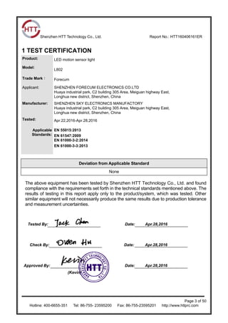
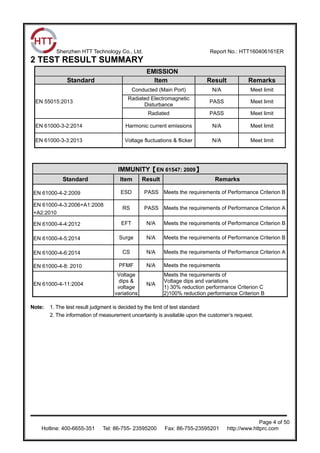

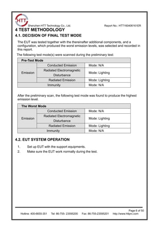


This EMC test report summarizes emissions and immunity testing conducted on various LED motion sensor light models produced by Shenzhen Forecum Electronics Co., Ltd. Testing was performed at Shenzhen HTT Technology Co., Ltd. and included conducted emissions, radiated emissions, harmonics, voltage fluctuations, electrostatic discharge, radiated RF fields, electrical fast transients, surge immunity, conducted RF, power frequency magnetic fields and voltage dips. The light models were found to comply with various standards including EN 55015, EN 61547, EN 61000-3-2 and EN 61000-3-3.


