SlideShare a Scribd company logo
Celebrating Our 100th Issue
SPECIAL COLLECTOR'S EDITION
Vol. 17/No. 100
ClassicCabinetStyk
WORKBENCH
No. 100 August, 1995
Editor
Executive Editor
Managing Editor
AssistantEditors
Creative Director
Senior Illustrators
Illustrator
Photographer
Electronic Graphics
Design Director
SeniorDesigner
Shop Manager
ShopAsst/Facilities
DonaldB. Peschke
DouglasL.Hicks
TerryJ.Strohman
Jon Garbison
MarkA. Williams
TedKralicek
David Kreyling
CindaShambaugh
DirkVerSteeg
Erich Lage
Crayola England
Chris Glowacki
KenMunkel
Kent Welsh
Steve Curtis
SteveJohnson
CIRCULATION
Sw6serijotionMancw7ers:SandyBaum,TroyJ.Dowell,
Paige Rogers • Assistant Subscription Managers:
Shane Francis, Julie Greenlee • Newsstand Manager:
Kent A. Buckton
PUBLISHING SERVICES
Mgr: Gordon Gaippe • Graph. Artist: Cheryl L. Cynor
CORPORATE SERVICES
Planning Director: Jon Macarthy • Controller: Robin
Hutchinson 'Account.: Laura Thomas • Bookkeeping:
Holly Lucas • Production Mgr.: Carol Quijano • Info.
Serv. Mgr.: Joyce Moore • Elec. Pub. Coord.: Douglas
M. lidster • Network Adm.: NickThielen • Admin.
Assistants: Cheryl A. Scott,Julia Fish* Receptionist:
Jeanne Johnson • Build. Maint: Ken Griffith
WOODSMITH MAIL ORDER
Art Dir.: Cindy Jackson • Catalog Prod. Mgr.: Bob
Baker • Inv. Control/Prod. Mgr.: Mark Mattiussi
• Proj. Supplies: LindaJones • Tech. Supp: Dave Stone
• System Operator: Tammy Aldini
CUSTOMER SERVICE
Manager: Jennie Enos'Team Leader: Karla Cronin
• Customer Service Reps.: Jennifer Murphy, Joy
Krause, Sara Kono, Anna Cox, Lonnie Algreen,
Adam Best, Kristi Andrews
SHIPPING DEPARTMENT
Supr: Nancy Johnson • Fulfillment Gloria Sheehan,
Chuck Carlson, Sylvia Carey, Larry Prine
WOODSMITH STORE
Manager: Dave Larson • Assistant Manager: Paul
Schneider»Sa£es Staff: Wendell Stone, Pat Lowery
• Office Manager: Vicki Edwards
Woodsmith® (ISSN 0164-4114) is published bimonthly
(Feb., Apr., June, Aug., Oct., Dec.) by Woodsmith Corp.,
2200Grand,DesMoines,IA50312.
Woodsmith® is a registered trademark of Woodsmith Corp.
Copyright© 1995 WoodsmithCorporation.Allrightsreserved.
Subscriptions: Single copy: $3.95. One year subscription (6
issues), $19.95. Two years (12 issues), $35.95. (Canada/For-
eign add $5 peryear, U.S. funds.)
Second Class Postage PaidatDes Moines, IAandataddi-
tional offices.
Postmaster: Send change of address to Woodsmith, Box
10718, DesMoines, IA50350.
Subscription Questions?Call 1-800-333-5075, 8:00am
to 5:00pm, CentralTune,weekdays.
E-Mail. Prodigy: EDJE97A, CompuServe: 75330,2301, Internet
75330.2301@compuserve.com.,AmericaOnline:Donpeschke.
Printed in U.S.A.
E D I T O R ' S C O L U M N
Sawdust
It's still hard to believe that this is the
100th issue of Woodsmith. To me, it
just doesn't seem that long ago that I was
working on the first issue. I guess time
does flywhenyou're havingfun.
READERS' GALLERY. To help celebrate
our 100th issue, I wanted to do something
special. Something a little different.
So a couple issues back I asked readers
to send in photographs of Woodsmith pro-
jects they had built. To say that I was
pleased with the response would be an un-
derstatement. I can't remember the last
time I had so much fun opening the mail.
Every daywe received dozens ofentries.
(There's one day's worth shown at the bot-
tom of this page.) And every day I was im-
pressed by the quality and variety of the
projects being built.
But best of all, it didn't seem to matter if
a person had been a woodworker for 22
years (like Mary Ellen Hampton), or they
were building their first woodworking pro-
ject. All of them seemed to share a genuine
love of woodworking. And that's some-
thing I'm proud to be part of.
All in all, we received hundreds ofphoto-
graphs. Many more than we could ever
hope to put on two pages. So we picked
photos that represented a wide variety of
Woodsmith projects. Congratulations to
those people whose projects appear on
pages 16 and 17. And to everyonewho sub-
mitted photos — thank you.
The Readers' Gallery isn't the only thing
special about this issue. We've also in-
cluded three special projects.
CLASSICWORKBENCH. The last time we
featured a traditional workbench was in
Woodsmith issue No. 50. But this time, in-
stead of a "European-style" bench with an
open base, we took a different approach.
We designed a classic cabinet style
workbench. (It reminds me of the kind of
bench you might have seen in a turn-of-
the-century woodworking shop.)
Besides offering plenty of storage for
various tools and accessories, this bench
also features a solid maple top. And an
easy to install, bolt-on woodworking vise.
As I said before, this bench has an old
fashioned feelto it. So we wanted to photo-
graph it in an old fashioned setting (see
the photos on the front and back covers).
The trick was finding the right setting. But
we found it right here in Des Moines: the
woodshopatLivingHistoryFarms. (Living
History Farms is an open air museum that
tells the story of Midwestern agricultural
and rural life.)
DOVETAIL CHEST. The other "old fash-
ioned" project in this issue is the dovetail
chest on page 18. It features traditional
hand-cut joinery and a shellac finish.
THREE-BOARD SHELF. Also, check OUt
the three-board shelf on page 28. It's a sim-
ple weekend project with a unique mount-
ingsystem.
Woodsmith No. 100
A L O O K I N S I D E
Contents
FEATURES
Classic Workbench . . . . . . . . . . . . . . . . . . . . . . . . . . . . . 6
Sturdy and solid — nothing on this workbench is fragile.
Even the metal visefeatures heavy wooden jaws, so it has
a wide clamping surface and holds a pair of bench dogs.
Laminated Top.................................... 14
There are two tricks to building aflat laminated bench top:
laying out the boards properly and gluing them up. We've
included some tips, techniques, and a simple jig for making
this process as easy and accurate as possible.
Readers* Gallery.................................. 16
Many readers responded to our requestfor snapshots ofthe
projects they've builtfrom past issues. Here's your chance
to see the work ofsomefellow woodworkers.
Dovetail Chest.....................................18
This heirloom chest isjust a box with a lid — and a sliding
tray inside. It'll give you a chance to use some traditional
woodworking techniques and an old-fashionedfinish.
Hand-Cut Dovetails 24
Ifyou've never cut dovetails by hand (or ifyou need a quick
"refresher course"), here's our simple step-by-step method.
Three Board Shelf 28
Nothing fancy here, just three boards. But don't miss the
unique hanging system. About all you needfor this project
is a boardfoot of lumber and an evening to build it.
Tips & Techniques............................... 4
ShopNotes 30
Sources................................................ 31
Classic Workbench page 6
-•**,
Dovetail Chest page 18
Hand-Cut Dovetails
Three Board Shelf page 28
No. 100 Woodsmith
"7T
F R O M F E L L O W W O O D W O R K E R S
Tips &Techniques
SANDER CONVERSION
• Sanding in tight places is
about as much fun as doing
taxes. You could buy an expen-
sive detail sander (the kind with
a triangle-shaped head), but in-
stead I converted my finishing
sander into one.
It's easy to do. Just change
bases. Simply remove the
screws and take offthe oldpad.
Then use it as a template to
mark the mounting holes for a
new base. But here's the best
part. You can make a new base
fit any shapeyou want.
This new base can be made
from almost any thin material.
But I like V4"-thick Masonite.
The self-adhesive sandpaper I
use seems to stick better.
Jace Laakso
Missoula, Montana
Remove existing
base and install
auxiliary base
* Masonite base
Cut base to any
shape you need
45° CORNER CLAMP
• I was recently working on a
displaycabinetwith a glassfront
built at a 45° angle Qike a bay
window). The problem was try-
ing to clamp and glue the front
frame pieces together. That's
because the frame pieces were
ripped at 22^° (halfof45°).
My solution was a two-piece
clamping jig. There's a base
piece with an opening cutin itto
match the angle ofthe miter, see
drawing below. It cradles the
workpiece and keeps it from
moving. A clamping block on
top pushes the workpiece down
against the angled base. That
way when the clamp is tight-
ened the mitered pieces are
squeezed tight together.
Orville Heitkamp
Belle Plaine, Minnesota
Base cradles workpiece
while clamping block
ROUTER FENCE INSERTS
• I need a large opening (for
clearance) in my router table
fencewhenusinglargebits. But
a large opening isn't safe when
routing small pieces— they can
wedge between the bit and
fence causing kickback.
Tosolvethisproblem,Iadded
a replaceable insertto myfence.
Itfills in the space around the bit
so small pieceswon'tgetcaught
in the opening.
To make an insert for your
fence, simply rout a shallow
mortise Qike the mortise for a
hinge) around the opening, see
Fig. 1. It's cut a little larger than
needed forthewoodscrews that
hold it in place. And just deep
enoughtoequalthethicknessof
the insert. (I used a V8"-thick
piece of Masonite.)
I make an insert for each bit.
For a straight bit, simply raise it
in the router table and cut out
the insert, see Fig. 2.
But for profile bits, the bear-
ing gets in the way. So first cut a
clearance slot in the insert, and
then cut the profile, see Fig. 3.
Mark Muncie
Indianapolis, Indiana
1 Cut insert to cover
opening in fence
Router table fence
For straight bits, simply
raise the bit to cut a slot
Insert
t
Straight
~" bit
FIRST: Cut out slot for
bearing clearance
SECOND: Raise profile bit to cut
insert to the same shape
Insert
Profile bit
Woodsmith No. 100
BAND CLAMP BLOCKS
• I like to use a band clamp and
corner blocks to glue-up mi-
tered pieces. But on many
blocks, the strap "hangs-up" on
a sharp outside corner. So I
made a set ofcorner blocks with
a rounded outside edge.
You cut all four blocks from a
IW-thick blank, see Fig. 1. But
it's easier to do most of your
work on the blockswhile they're
still part ofthe blank.
First, lay out all of your cuts.
Then make a partial saw cut on
all four sides to define the block
size, see Fig. 1. The diameter
can be cut next on the band saw
and sanded smooth.Then drill a
1/4"dia.clearanceholeineachof
the blocks.
Next, a shallow
groove is routed
around the outer edge to
hold the strap, see Fig. 2.
A tall fence supports the work-
piecewhen rolling itpastthebit.
And aMasonitebase covers the
hole in the tabletop so the work-
piece won't drop into it.
Now cut the blank into four
blocks. To do that, first band
saw the pieces apart, see Fig. 3.
Thenusethetable sawto cutthe
inside corners exactly 90°.
Mark Routzahn
Tiffin, Ohio
FIRST: Make partial
cuts to divide blank
into four sections
Usebandsaw
to cut out
blocksRoll
workpiece
past bit
to make
groove
Saw
between
kerfs
Tall auxiliary
fence
Wdiameter >
clearance hole
Rotate block 90° to
make second cut
Va" Masonite
auxiliary base
SECOND: Cut out
circle and drill
clearance holes
QUICK TIP
• Clamp pads can prevent a
lot of dents. But instead of
buyingthem, Imakemyown.
These pads are cut from
sheets ofheavy duty felt avail-
able atmost hardware stores.
Self-adhesive backing holds
them on the clamp jaws.
Ed Flietner
Phillips, Wisconsin
SILL COCK KNOBS
• A quick replacement for large
plastic knobs, like you'd find on
a router table, is a carriage bolt
and a sill cock handle (the metal
handle from a water spigot), see
Fig. 1. Both are available at local
hardware stores.
Sill cock handle
and carnage
bolt replaces
studded knob
Simply insert a Vi" carriage
bolt in the handle and add a nut
and washer, see Fig. 2. The
square shank on the bolt, fits the
opening in the handle perfectly.
Gary Adler
Gassville, Arkansas
SUBMIT YOUR TIPS
If you would like to share
an original shop-tested tip,
send it to Woodsmith, Tips
and Techniques, 2200 Grand
Avenue, Des Moines, Iowa
50312. Orifit'seasierforyou,
FAXitto us at: 515-282-6741.
E-Mail: 75330,2301@com-
puserve.com.
If we publish it, we will
sendyou$30to$150,depend-
ing on the published length.
Include a brief explanation
and sketch (or photo). And
don't worry, we'll rewrite the
tip and redraw the art if nec-
essary. Also, please include a
daytime phone number.
No. 100 Woodsmith
F E A T U R E P R O J E C T
Class& Workbench
The base of this workbench does more than support the top. The trays and
drawer store a shop's worth of tools — within easy reach.
ost shops can always use more storage
space. So why not build a workbench
where the base not only supports the top but also
provides space inside for your hand and power
tools? That's the idea behind this workbench.
And to make it easy to use this storage space,
a drawer and two trays ride on full-extension
slides to keep your tools accessible.
Then there's thetop.Thislaminated, hard ma-
ple top adds considerable weight to a storage
cabinet already filled with tools. When you com-
bine the two,you endupwitha"rock-solid"work-
bench capable ofhandling most any project.
To hold these projects on the bench, there's a
metal woodworking vise attached to one corner
with a thick, maple-block covering the front jaw.
A pair of dog holes in the block line up with the
holesinthebenchtop so bench dogs canbe used
to hold bigprojects.And thevise is easyto install.
Just four lag screws hold it in place.
Woodsmith No. 100
Construction Details
Record #52'/2 ED vise
withquick-release
mechanism
Made from
strips of 8/4 hard maple
glued face-to-face
BASE:
Outside case is made from
cherry hardwood and plywood
Interior framing and
drawers made from maple
hardwood and plywood
NOTE:
Complete cutting diagram
and materials list on page 13
CROSS SECTION
END VIEW
———— 22%" —————
Drawer
wood knobs
Frame and
panel doors
Hardwood
kickboard
_ Ball catch
for doors
Note: Drawer and trays
are mounted with full-
extension drawer slides
Trays-
VISE DETAIL
CROSS SECTION
Solid steel
handle
The Record #52V2 ED vise with
woodjaws has an open capacity of 9%"
Frame and
panel back
- 19V2"-
Wood
spacer
_ Quick-release lever allows ^- Vise mounted with (4)
vise to open and close freely V2" x 3" lag screws
HARDWARE LIST
• (1) Record #52V2 ED Vise
• (2)#14x2" RhWoodscrews
• (4) 1/2" x 3" Lag Screws
. (4) 1/2" Washers
• (4) 1V4"-dia. Wood Knobs
• (2pr.)2" x13
/s" Ball-tipped
Hinges
• (2) Ball Catches
(8) #4 x 1/2" Fh Woodscrews
(4) 1/4" x 3" Lag Screws
(4)V4" Washers
(20) #8 x 13/4" Fh Woodscrews
(36) #8 x 11/4" Fh Woodscrews
(16) #8 x 1" Fh Woodscrews
(3 pr.) 16" Full-Extension
Drawer Slides
No. 100 Woodsmith
apairofcase sides (J)arecutnext,seeFig.
2.These arejust3
/4M
-thickpieces ofplywood
with 3
/8M
rabbets cut on both edges. Each
rabbet forms a tongue that fits into the
grooves alreadycutin the stiles, see Fig. 2a.
Then assemble the sides and frames and
glue and clamp the case together. After
tightening your clamps, checkthatthe case
remains square.
CHAMFER STILES. With the case assem-
bled, I routed a decorative stopped chamfer
on all four corners, see Fig. 3. (Itworks best
to rout this chamfer in several passes.)
CLEATS. Next, I turned my attention to
the inside ofthe case, starting atthe bottom
and working my way up.
First, I cut a pair of front/back cleats
(K)andapairofsidecleats(L)tofitinside
the case, see Fig. 4. These cleats are posi-
tioned so the case bottom (added next) will
fit flush with the top edge of the bottom rail
on the front frame, see Fig. 4a.
BOTTOM. After the cleats are installed,
thecase bottom (M) canbe cutto size, see
Fig. 4. This piece of V£"-thick plywood rests
on the cleats and helps strengthen the cabi-
net when it's glued and screwed in place.
STIFFENERS. On most projects, I'd be fin-
ished with the cabinet once the bottom was
installed. Butnothere. Instead, to make the
case stronger, I added frame stiffeners.
These W-thick pieces of maple cover the
joint lines on the frames. It's an easy way to
strengthen the stub tenon joints.
I started by cutting three horizontal
stiffeners (N) tofitinside the case, see Fig.
5. Two fit behind the top rails on the front
frame, while the third is glued to the top rail
of the back frame, see Fig. 5a.
Next, I addedvertical stiffeners. First, the
vertical stiffeners (O) are glued and
screwed to thebacktwo corners ofthe case
CROSS SECTION
CASE
BOTTOM
(%" plywood)
Fh
I woodscrew
#8x1%"Fh
woodscrew
NOTE: Bottom fits flush
with top of rail
NOTE:
Cleats cut from
%"- thick stock
-<K) CLEAT (I'A'-wide)
HORIZONTAL STIFFENER^
(%'x 2'x 34W) la CROSS SECTION
Stiffeners glued !
to rails to
strengthen frame
NOTE: i
Glue stiffeners
in place
between the horizontal stiffener and case
bottom, see Figs. 6 and 6a. The other ver-
tical stiffeners (P) and (Q) fit along the
sides of the drawer and door openings and
are glued and clamped to the front frame.
MOUNTING CLEATS. Now to hold the top
in place later, I added a pair of mounting
cleats (R). These are just 3
/4"-thick pieces
of stock glued and screwed flush with the
top ofthe case sides, see Figs. 6 and 6b.
KICKBOARD. To complete the case, all
that's left is to install a kickboard.
First, I cutthe stockto finishedwidth (4")
with a V£" chamfer routed along the top
edge. Then the front/back kickboards
(S) and side kickboards (T) are mitered
to fit around the base and are glued and
screwed in place, see Figs. 7 and 7a.
MOUNTING
R)Ci£A7
VERTICAL
STIFFENER
NOTE: Glue
and screw
stiffeners to
backs of stiles
O. CROSS SECTION
(TOP VIEW)
K. l_KUii iCtllUIH
(SIDE VIEW)
#8x 13
/4"
Fh woodscrt
^
^  
V-N
•«-7!4-*-
w
f^
iltl
ft
fi?
^
l l
a.
CROSS
SECTION
(SIDEVIEW)
Miter
kickboards to
fit around case
No. 100 Woodsmith
DRAWER, TRAYS, & DOORS
Once the outside ofthe case was finished, I
turned my attention to the inside to add a
pair of trays and a drawer.
CLEATS. Iplanned on usingfull-extension
slides for the drawer and trays. But the
slides couldn't be screwed to the case sides
because the frame stiffeners got in the way.
So I added slide cleats (U) to provide a
mounting surface for the slides, see Fig. 8.
These cleats are3
/4M
-thick pieces of stock
screwed to the frame stiffeners. They don't
extend all the way to the front of the case,
otherwise the doors and drawer wouldn't
close all the way, see Fig. 8a. To get the
needed clearance, I installed the cleats Vie"
back from the inside face ofthe front frame.
TRAYS. With the cleats installed in the
case, I began workon the trays. Idecidedto
use pull-out trays because it makes it a lot
easier to get at your tools — especially the
ones at the back.
To determine the size of the front/back
tray pieces, first measure the opening be-
tween the cleats (mine was SOVfe"). Then
subtract 1" for the thickness of two slides
and Vfe" forthelapjointsatthecorners. Find-
ing the size of the tray sides is easier. It
matches the length ofyour slides (16").
I used these measurements to cut the
trayfront/back(V) andsides (W)tofin-
ished size, see Fig. 9. (My tray was 16" x
29W.) Next, I cut a 3/4"-wide rabbet atboth
ends ofthe sidesforlapjoints tojoin the tray
pieces together, see Fig. 9a. Then a groove
can be routed on the inside face of all the
tray pieces to hold a W-thick piece of ply-
CROSS SECTION
(SIDE VIEW)
® SLIDE CLEAT
NOTE:
Install cleats
and slides
VK" from
front frame
Screw cleats
to vertical
stiffeners
16" full-
extension
drawer
slide
NOTE:
Slides mount to cleats
with screws
wood for a bottom, see Fig. 9b.
Makingthetraybottom (X)fromWply-
wood keeps it from sagging when loaded
with tools. It should fit snug in the tray
pieces before you glue the tray together.
DRAWER. With the trays complete, the
drawerisbuiltnext. What's differentis how
the drawer is held together. It has hand-cut
dovetails for strength and durability.
Here again, you want to measure the
opening before making any cuts. Then cut
the drawerfront/back (Y) and sides (Z)
to finished size and lay outand cutthe dove
tails, see Figs. 10 and lOa. Formore on cut-
ting dovetails, refer to page 24.
Nowroutagroovetoacceptadrawerbot-
tom, see Fig. lOb. Once again, I used VzH
-
thickplywoodforadded strength.Thencut
the bottom (AA) to fit tight and glue and
clamp the drawer together.
TRAY SIDE
TRAY FRONT
a.
SIDE
V2"
TOP
VIEW
' FRONT/BACK-
END VIEW
Size groove
to match
plywood v / J~
L^' I
I
10 Woodsmith No. 100
You'll probably notice the groove cut for
the drawer bottom is still visible on the
drawer front. But don't worry about it. It'll
be hidden by a false front added later.
SLIDE INSTALLATION. After the drawer
and trays are complete, the next step is to
install the full-extension drawer slides. I
used a pair of 16" slides for the drawer and
each tray. (To find sources forthe hardware
you need to build this bench, see page 31.)
Basically, installing the slides is a two-
step process. First, one half of the slide is
screwed to the slide cleat in the case, see
Fig. 8. Then the other halfis mounted to the
drawer or tray, see Figs. 11 and lla.
FALSEFRONT. With the drawer installed
in the case, a false front (BB) is added
next. This is just a 3
/4M
-thick piece of stock
that fits in the case with a Vie" clearance all
around, see Fig. 12.
Before screwing the false front to the
drawer, I drilled a pair of V2"-dia. holes for
some wood knobs. Then install the false
front, keeping the needed clearance around
the drawer and glue the knobs in the holes.
DOORS
The last thing to add to the cabinet is a set
of doors. The unique thing about these
doors is they're cut to fit tight first — then
trimmed for clearance later.
The goal here is to have a Vie" clearance
on the top, bottom, and along the sides of
the doors, see Fig. 14. You also need the
same clearance (Vie") between the doors in
the middle. So I measured the opening in
the frame first (19Vs" x 32") and then cutthe
16" full-
extension
drawer slide
NOTE:
Center of
slide aligns
with layout fine
Exposedgroove
will be hidden
by false front
Maintain Vie
gap around
arawer
stiles (CC) and rails (DD) f or a tight fit, see
Fig. 13. But remember to allow for the ten-
ons when cutting the rails to length.
Note: Later, after the doors are assembled
you can trim them for the Vie" clearance.
Next, a groove is routed in all the frame
pieces to match the thickness ofthe center
panel, see Fig. 13a. And to hold the frame
together, tenons are cut on the ends of the
rails to fit snug in the grooves, see Fig. 13b.
Thenadoorpanel (EE)iscuttofitineach
frame before gluing the door together.
Now a pair of hinges can be installed on
each door by mortising them into the front
frame and door stiles, see Figs. 13 and 14.
Here, I used acouple pennies for spacers to
hold the door in position while installing the
hinges, see Figs. 14a and 14b.
Finally, to complete the doors, a pair of
knobs is attached to the door stiles. And a
pair ofball catches is installed in the cabinet
to hold the doors closed.
Center 1W-dia
knob on width
of door stile,
see Fig. 13.
NOTE:
Keep a '
clearance
around doors,
see detaila.
fb
- s
(T<
x '> V
J
1_* 1
=
f- •
CROSS j
ECTION
M> VIEW) ',
  '• /
^/P
P
K
/'
^————, 
i Mortise hinge
DOOR int0 D0th door
STILE anci front frame
No. 100 Woodsmith 11
BENCH TOP
After the cabinet is complete, I
worked on the bench top next.
Note: For more on building lami-
nated tops, refer to page 14.
STRIPS. This laminated top
consists of 13 bench top strips
(FF). These strips are l3/4"-thick
pieces of stock cut to a finished
lengthof62"andaroughwidthof
39
/i6". Later, the top is sanded to
its final thickness (3W), see ex-
ploded view at right.
ALIGNMENTHOLES. To keep all
the strips aligned when gluing
them together, I drilled holes for
short lengths of ^"-dia. dowels,
see detail 'a.' But remember, the
two outside strips (1 and 13) only
have holes on one face.
DOGHOLES. You could glue
the bench top strips together
now. But I didn't want to wrestle
with a heavy top. And there are
still a few things left to do.
First, a series of 3
/4"-dia. dog
holes are drilled in the top for
bench dogs, see detail 'b.' Referto
page 31 for sources of bench
dogs. Then rout a Vs" chamfer
around each hole to soften the sharp edges.
ROUNDOVER. Next, the corners on the
two outside strips are rounded over, see de-
tail 'c.' Note: But don't round the corner at
the end where the vise will be mounted.
NOTCH. There's one more thing to do be-
fore gluing the top together. And that's to
routapocket in the front strip for mounting
a metal vise. The back jaw of the vise slips
into this pocket. This way, the metaljaw is
CROSS SECTION (BENCH STRIPS) c. CORNER DETAIL
BENCH TOP
STRIP
J CROSS SECTION
(FACE BLOCK)
U CROSS SECTION
(BENCH STRIPS)
ft'-dia.
dog hole
Sana to final
thickness of 3Vi
covered by the front strip, and you have a
long, smooth surface to clamp against, see
Figs. 15 and 18.
GLUE-UP. With the pocket routed, the
bench top strips can be glued together, see
Fig. 16. Later, I used a belt sander to sand
the top and bottom faces smooth.
BENCHTOP INSTALLATION. Once the top
is sanded, it can be attached to the cabinet.
Butfirst I routed an Vs" chamfer around the
bottom edge, see Fig. 17. Then position the
top so it's centered side to side with a IVi"
overhang on the back, see Fig. 17a. Now
drill shank holes through the cleats in the
cabinet and use 3" lag screwswith washers
to hold the bench top in place.
VISE
With the top secured to the cabinet, thevise
can be installed next. I used a Record vise,
15 Rout pocfcet
in bench strip
for vise jaw
9Vis"
CROSS SECTION
n
Topedge
Front
strip (Ato.7.)
I
Do not use
alignment dowels
in first two holes
17 Laminated
Top
FRONT VIEW
Install top so it's centered
side-to-side on cabinet
NOTE:
Before mounting top to base
rout Vs" chamfer
around bottom edges
CROSS SECTION '-*'
(SIDE VIEW) chamfer-^
washer
~- VA" x 3" lag screw
12 Woodsmith No. 100
model #521^ ED. It features a quick-release
on the frontjaw, so it can be moved in or out
with the touch of a lever.
VISEINSTALLATION. But before installing
the vise, I added a spacer block (GG) to
make the top ofthe face block (added next)
level with the bench top. This 3
/4"-thick
piece of stock is cut to match the mounting
plate on the vise (in my case 5" x 9"). Then
drill VS"-dia. mounting holes through the
spacer block and screw the block and vise
to the bench top, see Fig. 18.
FACE BLOCK. After installing the vise, I
covered the front jaw with a thick maple
block. This block protects your workpiece
and also spreads the clamping pressure
over a larger area.
To make the face block (HH), glue to-
gether a couple pieces of stock to create a
2W-thick laminated piece, see exploded
viewand detail 'd' onpage 12.Then drilltwo
3
/4M
-dia. dog holes in the face block and
round over the two outside corners. Now
rout a Vs" chamfer on the bottom edge and
attach the face block to the vise, see Fig. 18.
To complete thebench top, I used ahand-
held router to rout a Vfe" chamfer on the top
edge (including the vise), see Fig. 19. It re-
moves the sharp edge left over from sand-
ing the top smooth. Q
Rout Vs" chamfer
around top edges
NOTE:
Chamfer
top edge
of face block
with vise
closed
MATERIALS LIST CUTTING DIAGRAM
CASE
Case Bottom (1)
A
B
C
D
E
F
G
H
I
J
K
L
M
N
O
P
Q
R
S
T
U Slide Cleats (6)
V Tray Fr./Bk. (4)
W Tray Sides (4)
X Tray Bottoms (2)
Y Dr. Fr./Bk. (2)
Z Dr. Sides (2)
3/4x2-32V5
3/4 X 2 - 323/4
3/4 X 67
/8 - 323/4
3/4 X 3 - 243/8
V4ply. - 15V4X243/8
3/4X2-32V5
Bk. Stiles (2)
Bk. Upper Rail (1)
Lower Rail (1)
Center divider (1)
Back Panels (2)
Fr. Stiles (2)
Fr. Upper Rails (2) 3/4 x 2 - 323/4
Fr. Lower Rail (1) 3
/4 x 43/8 . 323/4
Filler Strips (1)
Case Sides (2)
Fr./Bk. Cleats (2)
Side Cleats (2)
1
/4 x 3/8 - 60 (rgh)
3/4 ply. -171/4X32V5
3/4 X 1 V4 - 341/i
3 / 4 X 1 V 4 - 1 4
1/2 ply. -16V2 x 341/5
Hor. Stiffeners (3) 3/4 x 2 - 34V2
Vert. Stiffeners (2) 3
/4 x 11/4 - 28Vs (rgh)
Vert. Stiffeners (2) % x 1V4 - 5V5 (rgh)
Vert. Stiffeners (2) 3/4 x 1V4 -191/5 (rgh)
Mntg. Cleats (2) 3/4x1V4-15
Fr./Bk Kickbrds. (2)3/4 x 4 - 37V5
Side Kickbrds. (2) 3/4 X 4-19Vi
3/4X13/4-161/2
3/4X13/4-29
3/4X13/J-16
1/2 ply. -15'/4 x 283/4
3/4 X 43/8 - 29V2
3/4X43/8-16
AA Dr. Bottom (1) V2 ply. - 151/4 x 283/4
BB Dr. False Fr. (1) 3/4 x 47/3 .317/3
CC Door Stiles (4) 3/4 x 21/5 -19Vs
DD Door Rails (4) 3/4 x 2 Vs - 113/4
EE Door Panels (2) 1/4 ply. -113
/4 x 14%
BENCH TOP
FF Bench. Strips (13) 13/4X39/16 - 62
GG Spacer Block (1) 3/4 x 5 . g
HH Face Block (1) 2V2X4V8-14
%" x 9"- 96" Cherry ( 6 Bd. Ft.)
T
T
S —
S -7
B '' '/
G ///
G /.'/
/// / /. '/'// /
/' /
// / ///
%" x 7"- 96" Maple (4.7 Bd. Ft.)
—————— N————————
————— w——————
——————————O———
———u——————u
I 0 ! /^ f /
u —— Y/////-, — . .. .. . . V /•////
%"x4"-96" Maple ( 2.7 Bd. Ft.) ^ —— — - '
———————V————————— ——————— V ———————— ——— W ——— ——— W ———— '/'
/ / 1
%" x 6"- 96" Maple (4 Bd. Ft)
Y
L 1 L
Y
I ft I ft
2 Z //,
K ' V
%" x 5"- 72" Cherry (2.5 Bd. Ft.)
A
A
F
F
' // /
'/ / /
V x 7"- 72" Cherry (3.5 Bd. Ft)
C
BB
K
%" x 5"- 72" Cherry (2.5 Bd. Ft.)
•/.,,?»,,.,%
%"x6"- 72" Cherry (3 Bd. Ft.)
CC
CC
1%"x5"- 96" Maple (6.7 Bd.
CC DD DD
CC DD DD
Ft.)
FF
l%"x8"-72" Maple (6boards@ 7.5Bd. Ft. ea.)
FF
FF
//// ALSO NEED:
'/// Vt"x48"x48"
Vi' x 48" x 48"
/ ///, •'/, Maple plywood
3
/n" x48" x48"
Cherry plywood
'// //
HH HH X^
GG •- ^N %" thickness

''/'/' /
/' 
3
A" thickness
No. 100 Woodsmith 13
W O O D W O R K I N G T E C H N I Q U E
Laminated Top
Building a laminated top may
seem a little intimidating at first.
You have a lot of boards to cut
and fit together. But you don't
have to be a magician to get a
solid, tight-fitting top if you
know a few tricks. It only takes
two steps: laying outthe boards
so they're compatible with each
other and gluing them together
to avoid any gaps.
LAYOUT
Like drawing and discarding
playing cards to get a better
hand, the boards in a laminated
top need to be sorted for the
best fit and appearance. This
means checking each piece for
crook and bow but also arrang-
ingtheworkpiecessothetoplooksitsbest.
CROOK. The maple boards I used all had
a little crook and bow. But when trying to
assemble a laminated top, the crook of a
board can cause you more trouble than its
bow. So I checked for crook first.
Crook is warpage across the width of a
board running from end-to-end, see Fig. 1
and the Shop Tip below. It can be difficult to
"pull" a crooked board straight. So do you
discard all the boards with crook? Well, if
there'smore than Vs" ofcrook, I'll cutitinto
shorter pieces for another project.
Boards with less than Vfc" ofcrook can be
used — if they've been sorted first. I ar-
range them so the crooks oppose each
other, see Fig. 1. This way when the pieces
are forced flat, the crook is canceled. To
keep track of the direction, I'll
mark an arrow on the board
pointing to the crook.
BOW.Whenyou'veidentified
the crook, you can sort the
boardsto minimize bow. Bowis
warpage along the edge from
end-to-end, see Fig. 2. Unlike
crookedboards, you can usually
pull a bowed board straight.
That's because you're straight-
ening the board across its thick-
ness (not across the width).
Here again, arrange your
boards so the "bows" oppose
each other. I'll put my straight-
estboards ontheoutsideto help
pullthe rest ofthe bowed pieces
straight. Note: While rearrang-
ing the boards for bow, remem-
ber to keep the crooks opposed.
APPEARANCE.Withthepiecessortedfor
crook and bow, you still need to consider
how the boards will look when glued to-
gether. Small blemishes will be sanded out
when the top is leveled. But for larger de-
fects you should shuffle the boards again.
LABELPIECES. Onceyouhavetheboards
arranged for crook, bow, and appearance,
Arrows point to
crook of board
Arrange pieces so the
crook of the board
alternates
Arrange boards
so bowed
faces oppose
each other
Place the
straightest
boards on
the outside
SHOP TIP
Gap between string and
workpiece shows crook
Howmuch crook is there? It's
not always easy to tell. A simple
way to measure crook is to use
a string and some tape. Just
stretch the string from end-to-
end and tape it in place. Then at
the center measure the gap be-
tween the string and the board.
Dry clamp the pieces
together to check the fit
Arrow points
to face that
fits in jig -^
14 Woodsmith No. 100
C E L E B R A T I N G O N E H U N D R E D I S S U E S O 1
Readers'
Gallery
Over the years, a lot ofreaders have sent
us photos of projects they've built from
Woodsmith. Plus, we've received hundreds more
since I announced this gallery in the Sawdust
column a couple ofissues ago.
Of course, we couldn't include every photo.
What you see here is a sampling of the crafts-
manship andingenuityofourreaders. Somefol-
lowed our plans closely; others adapted them
quite a bit. We hope you enjoy seeing these
completed projects as much as we have.
Classic Workbench (Issue 50)
Donald Jacoby
Arvada, Colorado
Oak Rocking Chair (Issue 84)
TomBaker
San Diego, California
Editor's Note: Tom used black
walnut to build his oak rocker.
Saw Cabinet (Issue 47)
David Kerski
Eden Prairie, Minnesota
"This photo was taken in
my library because my
shop was too small."
Regulator Clock
(Issue36)
Chris Hellmuth
Middle Island, New York
Armoire (Issue 67) Armoire (Issue 67)
Bill Evans Bob Schuchard
Rehoboth, Massachusetts Fort Collins, Colorado
Editor's Note: Most readers customize ourprojects to some extent. Bill Euan's
cherry armoire looksjust like ours but has drawers inside. Bob Schuchard's
pine armoire has a scalloped base and raised panels on the sides.
Pedestal Desk (Issue 79)
R. E. Corbett, Jr.
Wilmington, North Carolina
"This is the only piece offurniture
in our house that both children
have requested when I die."
Classic Roadster
(Issue51)
Frank Pino
Edwardsville, Kansas
Garden Bench (Issue 93)
Bill Kilpatrick
Enniskerry, County Wicklow, Ireland
Rocking Horse (Issue 65)
William Murray
London, Ontario
16 Woodsmith No. 100
W O O D S M I T H W O O D W O R K I N G P R O J E C T S
Heirloom Cradle
(Issue 48)
Robert Kubiak
Omro, Wisconsin
Curved-Front Table (Issue 77)
Mark Hoecker
Charlotte, North Carolina
Oak Icebox (Issue 36)
RonAnderson
Atlanta, Georgia
"I'm brand new to woodworking. My
wife complains about never seeing me
anymore, but after seeing my first
results, she has slacked offa little."
ill
Tall Case Clock
(Issue70)
Steve Hart
West Linn, Oregon
Country Coat Rack (Issue 86) |
BobWhite
Muskegon, Michigan
SewingBox (Issue 78)
James Stephens
Ladson, South Carolina
"I used old pine pallets
for the wood to build
thissewingbox."
Country Pie Safe (Issue 55)
John Zelenak
Toms River, New Jersey
Blanket Chest (Issue 32)
Jack Couch
Pinson, Tennessee
Porch Swing-Glider (Issue 39)
James Galluzi
Poughkeepsie, NewYork
Country Hutch (Issue 96)
Bud Migues
Penn Valley, California
"Antiquing this hutch took
seven different finishes."
Ladder-Back Chairs (Issue 64)
LloydArundale
Ridge, New York
"The dining room chairs were the most challenging.
I started with six and ended up with five."
No. 100 Woodsmith 17
H E I R L O O M P R O J E C T
Dovetail Chest
The charm of this small chest is created with
two "old" woodworking techniques: cutting dovetails by hand
and brushing on a few coats of shellac.
You don't want to rush hand-cut dovetails.
Theyrequire careful, deliberate work.That
doesn't mean they have to be perfect. After all,
hand-cut dovetails aren't going to be machine-
precise — especially with wide panels. But that
fits the charm of this chest perfectly.
There's something to be said for a few quiet
hours in the shop. Working withoutthe roar ofa
router or breathing the clouds of dust. Okay, so
the pace is alittle slower, and theprocesstakes a
little longer. This is one time to throw out the
schedule. If you can put yourself in the right
frame of mind, the process is its own reward.
Come to think of it, applying the finish to this
chest is rewarding too. I wanted it to match the
"antique"characterofthe chest. Andwhatbetter
way than to use an "antique" finish?
Shellac has been used on furniture a long time,
and its color adds a natural warmth that's hard to
get from an off-the-shelf stain.
Ofcourse, manywoodworkers think ofshellac
as a "delicate" finish. And while it may not match
the durability of polyurethane, a lot of antiques
finished with shellac have put up with years of
wear. Andit's notdifficultto applyeither. Forstep-
by-step instructions, see the box on page 23.
18 Woodsmith No. 100
Overall Dimensions: 38Vs" x 79%" x 78'/s"
Wood: Pine - 43 bd. ft.
(See Materials list. Supplies list,
and cutting diagram on page 23.)
Finish: One coat of orange shellac
Two coats of blonde shellac
EXPLODED VIEW
Wide chamfer shaped
with block plane
NOTE:
All panels are
glued up from
solid wood
BASE
FRONT Dovetails cut by hand,
see a/t/c/e on page 24
LID-
BASE
END
Sliding Tray. Like the case, the sliding tray inside the
chest isjoined with hand-cut dovetails. This tray sits on
simple supports glued into thefront and back ofthe case.
TRIM
FRONT
-Tray slides back and forth
on wood supports
BOTTOM-
END VIEW
CROSS SECTION
BACK
TRIM
BASE
No. 100 Woodsmith 19
CASE
This dovetail chest starts out just as you'd
expect: gluing up oversized panels. There
isn't anything unusual or difficult about
these five 3
/4"-thick panels. The important
thing is that they are flat and all the same
thickness. This will make it much easier
when it comes time to cut the dovetails.
After the panels are glued up, the next
step is to cut the front/back (A) and end
(B) panels to finished size, see the drawing
at right. (The bottom will be cut to size
later.) I began by simply ripping each of
these panels to width. But when crosscut-
ting, the long panels require some extra
support.To dothis, Iadded alongauxiliary
fencetothemitergauge.Thisway,it'smuch
easier to get the panels square.
DOVETAILS. After the panels are cut to
size, work can begin on the dovetails. The
dovetailsarelaidoutSW oncenter, seeFig.
1. This allows for 3" tails and Vfe" pins.
Actually, not all the pins are V£". The top
one is alittle wider (1"). Butthe extrawidth
iscoveredby some moldingaddedlater, see
Fig. 2 and the drawing on the next page.
Note: Inthearticlebeginningonpage24,
there are step-by-step instructions for cut-
ting dovetails by hand.
GROOVES. When the dovetails are com-
plete, there are some grooves to cut in the
panels before you can assemble the case.
The first groove, near the top, is for the
tray supports. It's %" wide and cut in the
front and backpanels only, see Fig. 3.1 cen-
tered these grooves in one ofthe pin open-
ings.Thiswaythepinsontheendswillhide
the grooves when the case is assembled.
The other groove is for the bottom ofthe
chest, see Fig. 4. It's3
/4" wide and cut in all
fourpieces. This groove cutsthrough atail,
so it'll be visible from the outside when the
case is first assembled. But don't worry
aboutthis. Later, thegroovewillgetcovered
NOTE:
All case panels
are glued up from3
/4"-thick stock
by the molding at the bottom ofthe case.
BOTTOM. Now it's time to begin work on
the bottom panel. But to do this, first you
need to dry assemble the case. Then you
can measure the case opening for the final
size ofthe bottom, see drawing above.
Because the bottom is a solidwoodpanel
and not plywood, it needs enough room to
expandandcontractwithchangesinhumid-
ity.To allowforthismovement,Icutthebot-
tom (C) Vfe" smaller than the opening, see
Fig. 4a. (Mine was 15W x 35Vs".)
Cut 3
/s" x %"
groove in case
front and back only
Wide pin
at top is
covered by
trim molding
later, see
next page
NOTE:
To applypressure,
clamps should be
positioned over tails
Cut 3
/a"-deep
groove for bottom
in all case pieces
20 Woodsmith No. 100
CASEASSEMBLY. After the bottom panel
isready, youcangluethecase together, see
Fig. 5. (But don't use glue on the bottom.)
Thistakesquiteabitoftime, so Iusedwhite
glue. Itgives you a little more time to work.
Whiletheglueis drying, cuttwo W-wide
tray supports (D) to fit in the grooves in-
side the case, see Fig. 3.This time, I wanted
the glue to set up fast, so I used yellowglue.
Thatway, I didn'thave toworryaboutusing
clamps. Applying a little hand pressure for
a minute or two was all it took.
At this point, the case is essentially com-
plete. But if there are pins or tails protrud-
ing, you'll need to sand them flush with the
sides of the case, see the Shop Tip at right.
Once that's done, all that's left is to add the
base and some trim molding around the top
and bottom, see the drawing below.
BASE. I like the wide, thick base molding
I'veseenonsomeolderchests,andIwanted
the base on this chest to look the same. So
instead of using 3/4"-thick stock, I cut the
base pieces from 1Vi6M
-thick stock.
Thebase front/back (E) and base ends
(F) are first cut to rough length from 3"-wide
blanks. Next, cut a decorative chamfer
along the top edge, see Fig. 6.1 did this on
the table saw with the blade angled 15°.
Then to complete the base, miterthe pieces
to length and glue them to the case.
TRIM MOLDING. The next pieces to add
are some strips of trim molding, see draw-
ing below. Some of this trim will sit on top
of the base molding. The rest will end up
flush with the top of the case.
To make the trim front/back (G) and
trim ends (H), start with blanks that are
W thickand 2" wide, see Fig. 7. Routacove
along two edges using a W cove bit. Then
two 3
/4M
-wide (tall) trim pieces can be ripped
from each blank. Miter the pieces to length
and glue them in place. (The cove profiles
should face each other.) Here again, don't
Shop Tip: When using a belt sander, it's
easy to round over a corner. To prevent
this, clamp a scrap piece across the end.
worry about attaching the molding with
clamps. A little hand pressure works fine.
Finally, topreventchippingtheedgeifthe
chest ever gets dragged across the floor,
rout a W chamfer on the bottom edges of
the case and molding, see Fig. 8.
Rip chamfer on
top, outside edge
of base blanks
FIRST: Rout profile
SECOND: Rip trim to size
TRIM
FRONT/BACK
CROSS SECTION
V?
Rout chamfer around *
bottom edges of case
No. 100 Woodsmith 21
p
LID
Now that the case is complete, I started
work on the lid, see drawing at right. Just
like the other parts ofthe case, this means
you need to glue up another panel. But the
thickness ofthis panelis different: it's IHe".
Since you lift the lid from the edges, I
wanted it to overhang the case a bit. So to
determine the size of the lid (I), measure
the case (including the trim) and cutthe lid
panel 1" longer and wider.
CHAMFER. I also wanted the lid to have
the same chamfer that's around the base.
Butthe panel is too longto stand on end on
thetable saw. So I used ablockplane.
Before planing, lay out the edges of the
chamfer, see Fig. 9. Then plane down to
theselines, startingwith the ends ofthelid.
To avoid chipout, skewthe plane slightly so
the cut shears off thin shavings.
HINGES. When the chamfer is cut, mount
thelidtothecase.Todothis,Iusedaspecial
hinge. It has an offset barrel and doesn't re-
quire a mortise, see Fig. 10.
To mount the hinges, first screwthem to
the case. Next, setthe lid on top ofthe case
and center it side-to-side and front-to-back.
Then simplytrace aroundthebarrels ofthe
hingesonthebottomofthelid.Nowremove
the lid and hinges. Then screw the hinges
tothelidandreattachthehingestothecase.
IID SUPPORTCHAIN. The last thing to do
to the lid is add a 15"-long piece of brass
chain to the inside of the case, see Fig. 10.
This prevents the lid from dropping back.
Safety Note: If children will be opening
andclosingthislid,youshouldprotecttheir
fingers by installing a lid support. (For
sources, see page 31.)
#8x%
brass round
head screw
SHELLAC
When choosing a finish for this chest, I
wanted awarm, "aged" color. Butinstead of
trying to mimic an old finish, I decided to
use the real thing: shellac.
For this chest, I applied one coat of or-
ange shellac. The orange shellac gives the
wood itswarmcolor— and itdoesn'tblotch
like a normal stain will. But more than one
coat makes the wood too dark.
So to keep the color lighter but still add
moreprotection,Iappliedtwomorecoatsof
another "grade" of shellac: blonde shellac.
(Shellac comes in several grades, see page
31.) Actually, this isn't a different type of
shellac. It has just been purified more, so
there's not much color.
Shellac comes ready-to-use or in flakes
thatmustbe dissolved in alcohol. (See page
31, for sources.) Once dissolved, it begins
to slowlydeteriorate. So, Iusetheflakes and
mix my own. This way, Iknow it's fresh.
Though any alcohol will work, I dissolve
shellac in denatured alcohol. Shellac is
mixed in "pound cuts" — the number of
pounds of flakes to a gallon of alcohol. For
thischestIused a2 Ib. cut. ButIonlymixed
upapintofeachgrade (whichrequires4 oz.
ofshellacflakes).Anddon'tworryaboutbe-
ing precise. Just get it in the ballpark.
Shellac doesn't dissolve like Kool-Aid. It
takesseveralhoursormore. Pourtheflakes
into a non-metal container. (The shellac re-
acts to metal.) Then pour in the alcohol and
stir it. Let it set a bit Then stir it again. It's
agood idea to strain the shellac afewtimes
before using it, see photo.
Before applying the first coat of shellac, I
sanded the dovetail chest to 220-grit be-
cause the soft grain of pine tends to raise
when shellac is applied.
To apply shellac, I use a natural bristle
brush. The only trick is not to work the fin-
ish too much with the brush. The shellac
dries fast, so you can apply another coat af-
ter about three hours. Note: If the shellac
seems to be drying too quickly, then thin it
a little with more alcohol.
I sandedthe firstcoat lightly with 400-grit
paper. Then after the two coats of blonde
shellacwere applied, I rubbed outthefinish
with 600-gritpaper.
22 Woodsmith No. 100
TRAY
Withthelidattached,thelaststepistobuild
atraythatfitsinside the case and slides back
and forth on the tray supports.
First, the tray front/back (J) and tray
ends (K) are cut to finished size. Then to
join all the pieces ofthe tray, I cut the dove-
tails by hand — just like the case, see Fig.
11 and the drawing at right.
Next, I cut a W-wide groove %" deep in
each piece for the tray bottom, see Fig. 12.
The bottom is another solid wood panel.
Thistime, it'sgluedupfrom ^"-thickstock,
see drawing at right.
When the tray bottom (L) has been
glued up, I cut it to finished size. The panel
should fit inside the tray (including the
grooves) minus Vfe". Of course, a VS"-thick
panel won't fit into a W groove. But I cut a
rabbetalongthebottomedge ofthetraybot-
tom to create a Vi" tongue, see Fig. 12.
Next, I wanted to add some "handles" to
the ends ofthe tray. These handles are sim-
ply slots drilled and cut in the end pieces,
see Fig. 13. To do this, first drill l"-dia. holes
to establish the length of the handle slot.
Then clean out the waste with a sabre saw.
Nowsandthemandroutasmallchamferon
both the inside and outside edges. Then the
tray can be glued together.
With the tray assembled, there are two
steps left. First you want to chamfer the in-
sideandoutsideedgessothereareno sharp
corners, see drawing above right. And fi-
nally, don't forget to plug the holes in the
endpiecesthatwerecreatedbythegrooves
for the tray bottom, see Fig. 14. Q
TRAY BACK TRAY END
Va" chamferon
inside and outside
edges of tray
TRAY BOTTOM
'/2"x13'/2"x231
A'
TRAY FRONT
11
L_
2V2-
0TRAY
FRONT/BACK
12
TRAY
BOTTOM
k }, „ NOTE: Cut tray/s
bottom Va'smaller
than groove opening
W chamfer
on inside and
outside edges
MATERIALS SUPPLIES
A Front/Back (2)
B Ends (2)
C Bottom (1)
D Tray Supports (2)
E Base Front/Back (2)
F Base Ends (2)
3/4X18V*-36
3/4x181/4-16
3/4X3/8-;
1 Vie x 3 - 40 rgh.
1Vi6 x3 -20 rgh.
G Trim Front/Back (4)
H Trim Ends (4)
I Lid(1)
J Tray Front/Back (2)
K Tray Ends (2)
L Tray Bottom (1)
1/5x3/4-40 rgh.
1/4 x 3/4 - 20 rgh.
1V16X18-38
3/4 x 31/2 - 24
3/4 X 3'/4- 143/8
1/4x1314-231/8
• (1 pair) 3" No-mortise Hinges
• (1) 15" Brass Chain
• (2) #8 x 5/&" Brass Rh Screws
" x 5"- 96" (Four boards @ 3.3 bd. ft. each)
A A B
''/.
%" x 5"- 96" (Two boards @ 3.3 bd. ft. each)
B B
%" x 5"- 96" (Two boards @ 3.3 bd. ft. each)
'/2"x8"-96" (3.3 sq. ft)
1
L
'////////, '/, '///
L
^'/////, '/////. ty
L
'//////////;/
////
////
V x 8"- 96" (Two boards @ 6.6 bd. ft. each)
®
®
No. 100 Woodsmith 23
W O O D W O R K I N G T E C H N I Q U E
Hand^Cut Dovetails
A step-by-step approach to cutting dovetails in wide panels.
Plus, some techniques for assembly and a few troubleshooting tips.
Which comes first,
the pins or the
tails? Frankly, you can
cut them either way, but
I start with the pins. It's
how I was taught and
how I always cut them.
WHICH IS WHICH? But
maybe I'm jumping the
gun. After all, when look-
ing at this interlocking
joint, itcanbehardtotell
which one is the tail and
which is the pin.
The trick is to look at
justthe face ofthe board,
not the ends, see Fig. 1.
The tails flare out — like
a dove's tail. And from
the face, the pins are
straight, sort of like box
joints. The pins slide in
betweenthe tails, butun-
like box joints, they can
only slide in one direc-
tion.Theangledsidesactaswedges,soyou
can'tpullthem apart any otherway.
PINS FIRST. So why do I cut the pins first?
Thereareacouplereasons. First,Ithinkthe
pins are easier to cut. But it's also easier to
cut them accurately. (And ifthey don't end
up perfectly square to the baseline, it's easy
to clean them up so they are.) This is impor-
tantbecause after the pins are cut, you'll use
them to lay out the positions of the tails.
(Laying out the tails from the pins is also
easier than marking the pins from the tails.)
STOCK PREPARATION. Regardless of which
panelyou startwith, the pinpanelorthetail
panel, your first step is always going to be
the same: stock preparation.
FLAT& SQUARE PANELS. Whether you're
dealing with narrow boards or wide panels,
each piece mustbe flatand smooth. And the
ends of the boards must be square. In fact,
allthey should need is alittle finish sanding.
ORIENTATION. Whenyou're satisfiedthe
panels are as flat and square as you can get
them, the next thing to do is arrange the
panels.Theideaisto ori-
ent them so the finished
project will look its best
when it's put together.
When the panels are
oriented just so, I label
the outside and inside
faces, as well as the top
edges, see Fig. 2. Also,
it's a good idea to label
adjoining corners with a
letter. These steps don't
really take much time,
and when you transfer
the pinsto the matingtail
panels later, the labels
will saveyou alotofhead
scratching.
BASELINE. Finally, I
mark a baseline around
the ends of each panel,
see Fig. 3. The baseline
equals the thickness of
theworkpieces. Itshows
where to stop cutting.
To lay out the baseline on wide panels
(like those on the dovetail chest in this is-
sue), I use an adjustable square and a pen-
cil, see Fig. 3.Justsetthe adjustable square
to the thickness ofthe panel.
Note: Ifyou'reworkingwith smallpieces,
the easiestwayto lay outthe baseline is to
use the boards themselves. Stand up one
board and place it againstthe end ofthe ad-
joining piece. Then simply trace around it.
Now when all the panels are ready, you
can begin work on the pins.
NOTE: Set combination
square to thickness of panel
24 Woodsmith No. 100
PINS: STEP-BY-STEP
When cutting pins, there
are three things to do: lay
out the pins, make cuts on
each side of them with a
hand saw, and clean out
the waste between them.
LAYING our. The first
step is to lay out the posi-
tion ofthe pins. I start with
the outside face toward me
(the one with the narrow-
est part of the pins).
Next, the layout can be
drawn around to the inside
face. To lay out the angles
across the ends, I use a
bevel gauge, see Step 2.
In softwoods, this angle
is usually greater than in
hardwoods. (Iused14° for
the chest and 9° for the
hardwood drawer on the
workbench in this issue.)
Shop Tip: For a quick, easy set-up gauge,
miter a scrap piece at the angle you need.
When the pins are laid out, I always mark
the waste sections. This makes itharderfor
me to cut on the wrong side of the line.
All thismarkingand laying outmay seem
to take a lot of time. But it really does pay
off in the end. The key to making dovetails
as simple and accurate as possible is to be
able to see exactly what you're doing.
CUTTINGTHE PINS. At this point, the pins
can be cut, see Step 4. Here, it's important
to keep the hand saw straight up and down
so the pin ends up square to the baseline.
Again, I always keep the outside face to-
ward me. This way, I can be extra careful
with the good face. And if I'm off the line a
bit on the inside face, it won't be visible.
Note: If you don't feel confident using a
hand saw, just stay a bit more on the waste
side ofthe line. There will be more clean up
with the chisel, but you won't have to worry
about gaps when the joint is assembled.
REMOVINGTHEWASTE. When allthe pins
are sawn, the lastthingto do is clean outthe
waste between them, see Steps 5-7.
Here, I do two things. To ensure a clean,
straight baseline, I clamp a backing board
to the panel. But this board can shift out of
position. Especially when you start pound-
ing on the chiselwith amallet. So to prevent
this, I begin by removing tiny "bites."
Another thing I do is undercut the shoul-
der, see Step 6. After about Vfe" is removed,
I'll angle the chisel slightly toward me when
choppingoutthewaste.Thisway,it'seasier
to get a good, tight fit.
When all the waste is removed, you'll
need to spend alittletime cleaningup allthe
corners. And now's a good time to check
thateach pin is straightand square, making
any adjustments ifnecessary, see Step 8.
1 First, secure the panel with the out-
side face toward you. Then, lay out
each pin on the face of the panel. (This
will be the narrowest part ofthe pin.)
2 To lay out each pin on the etuis of the
panels, first set the bevel gauge. Then
hold a pencil on the mark, butt the gauge
to the pencil, and draw the angled line.
Waste - Save pencil
lines
3 Next, draw lines from the ends down
to the baseline. Then mark the waste
sections between the pins. Do this on both
the inside and outsidefaces ofeach panel.
4 The sides of the pins are formed by
cutting to the waste side of the lines
with a fine-tooth saw. Stop when the kerf
has reached the baseline on both sides.
5 To remove the waste between the pins,
first clamp a backing board along the
baseline. Then with a sharp chisel, care-
fully establish a small shoulder.
6 Now to remove the waste, chop straight
down. Then chip out the waste from
the ends. After removing an %", tilt the
chisel slightly and undercut the shoulder.
7 When half the waste is gone, flip the
panel over and clamp the backing
board in place again. Then repeat the pro-
cedure to remove the rest ofthe waste.
8 After cleaning up the corners with a
chisel, make sure each pin is straight
and square to the end ofthe board. Correct
any bad saw cuts with a chisel.
No. 100 Woodsmith 25
TAILS: STEP-BY-STEP
ill
After the pins are com-
plete, it's time to work on
thetails. Ilaid outthepins
with a ruler and a pencil,
but the tails are different.
They need to be cut to fit
the pins. So instead ofus-
ing a ruler, I mark the
tails directly from the
pins. This way, they will
match them perfectly.
LAYING OUT. To lay out
thetails, thefirststepisto
set the tail panel on the
workbench with the in-
side face up. Then stand
the pin panel on top sothe
two panels form a corner.
These panels should be
flush at the ends and the
edges with both inside
faces toward each other.
Here's where all that
marking at the beginning
really helps. It's impor-
tant that the corresponding corners match
when laying out the tails. And both panels
should be oriented correctly.
ShopTip:Tohelpthepanelstandupright,
I clamp a piece ofscrap to the panelwith the
pins before setting it on the tail panel, see
Step 1. This also helps remove any slight
cupping that may be in the panel.
Now that the tails are marked on the in-
side face, the lines can be transferred
around the panel to the outside face, see
Steps 34. Drawing the straight lines across
the ends ofthe panel is easy. Butto transfer
the angles to the outside face, you'll need to
use the bevel gauge again.
To be safe, I don'tjust draw the same an-
gle I used to draw the pins. Instead, I check
each angle on the inside face, adjust the
bevel gauge if necessary, and then transfer
this angle to the outside face.
CUTTINGTHETAILS. Cutting the tails is
different than cutting the pins. This time,
the saw isn't straightup and down — it's an-
gled instead, see Step5.Thismeans starting
the cut is a little trickier. So I usually start
more toward the waste side of the line.
(Mark the waste sections on the tail pieces
if you haven't done so yet.) This leaves me
with more to clean up, but the dovetails fit
together without any gaps.
REMOVING THE WASTE. With all the kerfs
cut, thelastthingto do isremovethewaste.
But this time, start with the dovetail saw
and remove the waste sections for the pins
at the top and bottom ofthe panel, see Step
6.Then clean upthe shoulderswith achisel.
Now you can clean out the rest of the
waste between the tails. There's nothing
tricky here. There's just not quite as much
room to work as with the pins, see Steps 7-8.
I To lay out the tailsfrom the pins,first
set the tailpanel on the benchwith the
inside face up. Then set the pin panel on
top so mating edges align.
2 Now, make sure the two panels are
flush at both the end and the edges.
Then carefully trace the pins onto the tail
panel using a sharp pencil.
3 Next, to extend the lines around the
panel, draw parallel lines across the
ends. To do this accurately, position the
pencil. Then slide the try square up to it.
4 Now transfer the angles on the inside
face to the outside face. Adjust the
bevel gauge to match the angle on the in-
sideface. Then draw it on the outside face.
5 To form the sides of the tails, hold the
saw at an angle and begin cutting,
staying on the waste side ofthe line. Stop
when the kerfreaches the baseline.
6 To remove the waste for the pins at
both the top and bottom, use the saw,
cutting from the edges toward the first
tail. Then clean up the cuts with a chisel.
7 Now to remove the waste between the
tails, use the same procedure as the
pins. Begin by clamping a backing board
to the panel and establishing a shoulder.
8 Remove half the waste. Then flip the
panel over and repeat the process. If
the saw cut didn't follow the line, use a
chisel to clean up the tails.
26 Woodsmith No. 100
FITTING & ASSEMBLY
Atthispoint, thejointcanbeassembled. But
first, you need to do some fitting.
FITTING. To get the joint to fit, you're
probablygoingtoneedtoremovealittlema-
terial from either the tails or the pins. But to
see just where to remove this material, the
joint should be dry assembled (as much as
possible), see photo at right.
But don't force it. Ifyou do, the pins at the
top and bottom can split from the pressure.
The goal is a fit that can be dry assembled
with a few light taps ofa mallet.
With the joint dry assembled as much as
possible, take a close look at each pin and
dovetail. You should be able to see where
the joint is binding. And when you pull the
joint apart, the tight spots will also be bur-
nished slightly. To make these areas easier
to see, I like to mark them with a pencil, see
the photo at right.
CHISEL. There are a couple ways to fit the
dovetails. To remove a lot of material, you
can pare it away with a chisel, see Fig. 1.
This removes the wood pretty fast, but it's
also easy to remove too much material.
SANDING STICK. So I often use a little
sanding stick, see Fig. 2. Basically, this is a
thin piece of scrap wood with some adhe-
sive-backed sandpaper attached. I bevel the
edges to match the angle of the tails. This
way, I can sand right into the corner.
ASSEMBLY. When all the joints fit, the
case (or drawer) is ready to be assembled,
see Fig. 3.1usewhitegluewhen assembling
large cases. It has a longer set-up time than
yellow glue, which helps with all the small
faces that need to be glued.
I usually applygluejustto the sides ofthe
pins andtails. I don'tbothergluingthebase-
line since it's end grain.
Clamping up dovetails usually takes a lit-
tle preparation. You onlywant to applypres-
sure to the tails (not the pins).
This isn't a problem with wide dovetails
like those on the chest. Butifyou don'thave
many clamps, you can distribute the clamp-
NOTE: Scrap piece with
adhesive-backed
sandpaper on bottom
side only
Use sharp
chisel to
carefully pare
away material
Bevel
edges to
fit into
corners
TROUBLESHOOTING
It's a good feeling when those pins finally
slide into the tails. But sometimes the joint
isn't quite perfect
PROTRUDINGTAILS*PINS. One common
problem iswhen eitherthe tails orpins stick
out. But this is easily corrected with a little
sanding, see the box on page 21. And if
there'stoomuchtosandoffquickly,youcan
ing pressure evenly across the joint with a
special clamping block, see Fig. 3. (This
block also works when the clamp head is
bigger than the tails, as on a drawer.) LI
Apply pressure
to tail panel only
Notched clamping
block distributes
pressure evenly
addanauxiliarybasetoyourrouterandrout
them flush, see page 30.
GAPS BETWEEN DOVETAILS. Gaps are a
much bigger problem. For instance, you
mighthave agapbetween atail and apin (or
between several tails and pins). This can be
fixed, but once again, you'll need to get out
your hand saw.
The idea is to cut an even kerf through
the gap, see Fig. 1. Then glue a spline in the
kerf to "patch" it, see Fig. la.
GAPS ATBASELINE. There's another pos-
siblegapyoumightruninto: agapalongthe
baseline of the tails. Here the cut was too
deep. The solution is to use wedges to fill the
gaps, see Fig. 2.
SECOND: Glue spline
in kerf and trim flush
To fill baseline
gap, glue in—
wedges and
trim flush
No. 100 Woodsmith 27
W E E K E N D P R O J E C T
Three
Board
Shelf
This evening project
makes use ofa unique,
invisible hanging system.
The nice thing about this shelf design
is that it's just as easy to build three
(ormore) asitistobuild one. Each requires
about a board foot oflumber. And there are
only three parts: two brackets and a shelf.
Plus,there's auniquehangingsystemthat's
completely invisible.
BRACKETS. To build a single shelf, start
with the two curved brackets. Their main
purpose isto supportthe shelf, butI also de-
signed them to hide the hanging hardware.
(More on this later.)
To make the brackets (A), cut a blank to
final width (4") but leave it long enough for
NOTE: Do not
rout bullnose profile
on these edges
both brackets. Then lay out and cut the
shape of the brackets at each end of the
blank, see Fig. 1 and the pattern below.
Before cutting the brackets to length,
rout a bullnose profile on the front and
curved edges. You don't need a special
router bit to do this. Just use a V5" round-
over bit in the router table with %" of the
e
cutting edge exposed, see Fig. 2. With the
edges routed, cut the brackets to final size.
SHELF. For now, set the brackets aside
and beginwork onthe shelf (B), referto the
drawing below left. I started with a blank 5"
wide and 25" long, see Fig. 3.
Withtheblankcutto rough size, nowdrill
four counterbored holes for attaching the
Use long blank to
cut two brackets
Vi* squares
28 Woodsmith No. 100
dia. x W deep
counterbore
dia. x %" cteep A>o/e
Router 
fence ~  "~
J^V]
NOTE:
Strike 12"
radius from
center of shelf
NOTE:
Rout slot in
multiple passesRaise bit to cut
through auxiliary base
brackets, see Fig. 3a. These are measured
from the center and are 16" apart.
Then, flip the shelf over and drill a couple
holes in the bottom ofthe shelf, see Figs. 3
and 3a.Theseholesprovidepocketsforthe
hanging system to hook into.
Now, there arejust a couple things left to
do to the shelf. First, cut a gentle curve on
each end, see Fig. 4. Then on the front and
ends of the shelf, rout a bullnose profile just
like the one on the brackets, see Fig. 2.
SLOTS. The shelf and the brackets are
about ready to be screwed together, but
there's still one more thing to do.
To hide the hanging hardware, you need
to routa slotin the back ofeach bracket, see
Fig. 5.1 did this with a Vi" straightbitin the
router table. And to make this procedure
saferwith such a small workpiece, I added
an auxiliarybasetocoverthelargeopening
in the table. Then I clamped a scrap block
to the fence to act as a stop.
ASSEMBLY. With the slots cut, the shelf
can be screwed together. Plug the holes
withshortpiecesof%" dowelandtrimthem
flush, see Fig. 6. Then to finish the shelf, I
wiped on a few coats of an oil finish.
HANGING SYSTEM. Okay, now it's time to
hangthe shelf.This shelfhangs on acouple
common L-hooks, see Fig. 7. Theyslide into
the slots in the brackets and then hook into
the holes on the bottom of the shelf.
There are atleast acouple waysto secure
the L-hooks into the wall. You can either
screw them directly into the studs. Or, if
you're going into drywall, you can use dry-
wall anchors, see the box at right. Q
<&
r————*
#8x1'/4" 9
Fh woodscrew
<"-diameter
dowel
Trim dowel
flush to shelf
FIRST:
Position
bracket
over L-hooks
SECOND:
Press down
to lock
L-hook
SELF-DRILLING DRYWALL ANCHORS
TheL-hooks usedtohangthese shelvescan
be screwed into a wall stud. But this will re-
ally limitwhere you can position the shelves
on the wall. Unfortunately, they don't pro-
vide enough holding power when screwed
directly into drywall. So what do you do?
I found that a couple drywall anchors
hold the L-hooks well. And the nice thing is
their tips are shaped like spade bits, so you
don't need to drill a pilot hole, see photo.
Drywall anchors are made from metal or
plastic and are available athardware stores.
(Oryou can order them from the mail order
source in the box on page 31.) Note: These
anchors won't work in plaster (or a stud).
^Ki|M||^u|H^|taHBH|
No. 100 Woodsmith 29
S O M E T I P S F R O M O U R S H O P
ShopNotes
DOVETAIL JIG
• The timing couldn't have
been better for receiving a dove-
tail jig design from Jeffrey
Kern ofBenicia, California. We
were just getting started on the
dovetailchest.Andhisjighelps
keep the saw aligned with the
lay-out lines when making the
cuts. (Refer to page 24 formore
on laying out dovetails.)
Thejigconsistsoftwopieces.
iGUIDE
BLOClC END VIEW
'- t
Angle ofj
dovetail
There'sablocktoguidethesaw,
and a clamping bar to hold the
jig in place.
Once you've decided on the
dovetailangle (Iused 14° forthe
dovetailchestonpage18,and9°
for the drawer on page 11), it's
easy to build the jig. Start with
the guide block, see Fig. 1. Both
the sides andkerfsusethe same
angle. The block is beveled on
GUIDE
BLOCK #8x1VSFh
Waste woodscrew
CLAMPING
BAR
Remove waste from guide
block after the glue dries
the sides for cutting the tails.
And has two angled kerfs for
cutting the pins.
Then glue and screw the
guideblocktotheclampingbar,
see Fig. 2. But don't cut off the
waste just yet. It keeps all the
pieces of the guide block posi-
tioned correctly on the clamp-
ing bar until the glue dries.
To use the jig, clamp it to the
Use kerfs to
guide saw when
cutting pins
end of the workpiece and start
on the pins, see Fig. 3. For more
on cutting dovetails, refer to
page 24. The only thing critical
here is to make sure the saw
blade stays tight against the
guide block on thejig.
Youcutthetailsthesameway.
Except this time, you'll use the
bevel on the side ofthe block to
guide the saw, see Fig. 4.
TRIMMINGDOVETAILS
• On page 21 we show a tip for-
trimming dovetails flush with a
belt sander. This works fine
when there isn't much material
to remove. But if the pins and
tails are cut a little long, there's
a quicker way to do the same
thing. Allyou need is a straight
bit and your router, see Fig. 1.
But first you have to replace
the existing router base with a
different one. That's because
the edge of a regular base runs
into the pins or tails before the
bit can get near enough to trim
them flush. To solve this prob-
lem, Imade anauxiliarybaseto
raise the router up so it doesn't
hit the dovetails.
This auxiliary base is simply
a 3
/4"-thick piece of stock with a
wide rabbet cut on the bottom,
see Fig. 2. The rabbet provides
the clearance needed so the bit
can reach the pins and tails. To
make the base stable, it's cutex-
tralong (minewas 11"). Andfor
added control, there's a block at
one end for a handle.
To use the jig, adjust the bit
height so ittrimsthe pins ortails
flush, see Fig. 3.
Pin stands proud
of workpiece
A straight bit
in a router will trim
the pins or tails flush
11"
J
Feed the
router slowly when
trimming the pins or tails
30 Woodsmith No. 100
P R O J E C T S U P P L I E S
1Woodsmith Project Supplies
offers hardware kits and sup-
plies for some of the projects
shown in this issue. Suppliesfor
these projects are also available
at your local hardware store or
through one of the mail order
catalogs listed below.
CLASSIC WORKBENCH
A complete hardware kit for the
workbench, shown on page 6, is
available from Woodsmith Pro-
ject Supplies. This kit includes
all the hardware you'll need to
build the bench (listed in the
Supplies box on page 7), except
for the vise and the hardware
needed to mount the vise.
W100-7100-100 Workbench
Hardware Kit...................$55.95
Note: Similar hardware is avail-
able from several woodworking
catalogs listed in the mail order
sources below.
VISE. We also added a metal
woodworking vise, the Record
52V2 ED, to our workbench, re-
fer to the photo on page 3. This
vise is available from the mail
order sources listed below.
Besides the vise, you'll also
need some mounting hardware.
Mounting the 52VS ED requires:
• (2) #14 x 2" Rh Woodscrews
• (4) W x 3V£" Lag Screws
• (4) ^" Flat Washers
ACCESSORIES. One way to im-
HOW TO ORDER
To order a project kit from
Woodsmith Project Supplies,
use our Toll Free order line.
It's open Monday through
Friday, from 7 AM to 7 PM
Central Time.
Before calling, please have
your VISA, MasterCard, or
Discover Card ready.
If you would like to mail
your order in, call the num-
ber below for more informa-
tion on shipping charges and
any applicable sales tax.
1-8OO-444-7527
Note: Prices subject to
change after October, 1995
Sourcesprove the versatility of a work-
bench is to add holdfasts and
bench dogs. Woodsmith Pro-
ject Supplies is currently offer-
ing a holdfast and two types of
bench dogs. (These are also
available from the sources
listed below.) Each of these ac-
cessories fits into the 3
/i"-dia.
holes drilled in the top of your
bench top.
woodworking vise. Normally,
bench dogs are square, but the
ones we're offering are round,
see right photo below. They're
made from solid brass, so
they're less likely to nick your
plane blades or chisels.
W100-1301-618 Bench
Dogs (One pair)...............$19.95
WONDERDOG.Another type
of bench dog is the Wonder
Holdfast. This simple holdfast
is a traditional clamp that can be
used to secure a workpiece to the
top of your workbench.
HOLDFAST. The first accessory
you might want to consider is
actually an old one: a holdfast,
see left photo above. It's one of
the simplest ways to secure a
workpiece to a bench. (Ours
will secure stock up to 4" thick.)
Simply drive the head down to
jamb the holdfast into the hole,
and it won't let up until you dis-
lodge it with a sideways tap.
W100-1301-600
Holdfast.............................. $9.95
TRADITIONALDOG. Another
traditional bench accessory is a
bench dog. It's used with a
Bench Dogs. These bench dogs
(right) and Wonder Dog (left)
are modern tools for making
your workbench mare useful.
Dog, see right photo. You don't
need to use a vise with this dog.
The body is round, but it also
has a 6"-long steel thread at-
tached to a brass head, so you
can apply pressure just like a
vise or a clamp.
W100-1301-616
Wonder Dog.....................$24.95
DOVETAIL CHEST
The dovetail chest on page 18
doesn't require much hardware.
For hinges, I chose some easy-
to-install 3" no-mortise hinges,
see sources below.
MAIL ORDERSOURCES
Similar hardware and supplies may befound in thefollowing
catalogs. Please call each companyfor a catalog or information.
Constantine's
800-223-8087
Recordvise, Vise accessories,
Mi-mortisehinges,Lidsupports,
Woodcraft
800-225-1153
Workbench hardware, Record vise,
GarrettWade
800-221-2942
Shellac flakes, Behkol
Woodworker's Supply
800-645-9292
Vise accessories, Shettac flakes, Behkol,
Drywatt anchors
Lid supports
Woodworker'sHardware
800-383-0130
Workbench hardware,
No^marttse hinges, Lid supports
TheWoodworkers' Store
800-279-4441
Workbenchhardware, Vise accessories,
No-mortise hinges, Lid Supports
But you'll need something to
prevent the lid from opening too
far. Forthis,Iusedabrasschain
and two screws. If children are
going to be opening and closing
the lid, I recommend using a lid
support that won't slam shut.
Check the sources below.
SHELLAC
To finish the chest, I used shel-
lac, see the box on page 22.
These days, shellac is used
mostly as a "stain blocker" that
you can buy ready-to-use at
manyhardwareandpaintstores.
Unfortunately, many manufac-
turersdon'tdatethecans,soyou
don'tknowhowlongit'sbeenon
the shelf. And shellac that's
been dissolved in alcohol only
has a shelf life of about a year.
Instead, I buy shellac flakes
and dissolve them with dena-
tured alcohol in aglassjar. (For
sources ofshellac flakes, seethe
listbelow.) Note:Behlensmanu-
factures a product specifically
for dissolving shellac called Be-
hkol, see below.
Ifyou decidetobuyshellacin
flakes,thereareanumberofdif-
ferent grades to choose from:
button lac, garnet, orange, and
blonde. Each isjustanotherstep
in the purification process. But-
ton lac is the darkest in color,
while the blonde is fairly clear.
WvdNet
COMPUTER BULLETIN BOARD
FORWOODWORKERS
• Project Plans to Download
•Woodworking Forums
• Finishing Forum
• Back Issue Indexes for
Woodsmith & ShopNotes
•ForPC and Mac
• FREE First Month
To log on to WoodNet, set your
communication program to 8 data
bits, 1 stop bit, no parity, full du-
plex, andANSI terminal emulation.
Then call 1-515-245-9663.
Ifyou have any questions, give us
a call: 515-282-7000 M-F 9-5 CST
No. 100 Woodsmith 31
A L A S T L O O K
Final Details
Hand-CutDovetails Page 24
Cutting dovetails by hand isn't
just for the experts. You can create
a tight-fitting joint with our step-
by-step instructions.
Dovetail Chest Page 18
With its clean lines and hand-cut
dovetails, this pine chest will fit
almost any room in your home.
Classic Workbench Page 6
Not only does this benchfeature a
solid, laminated top, it also has
an enclosed base to store a variety
of tools and accessories.
32 Woodsmith No. 100

More Related Content

Viewers also liked

mejorar la calidad de vida
mejorar la calidad de vidamejorar la calidad de vida
mejorar la calidad de vida
Juli Rios
 

Viewers also liked (8)

Acreditacion
AcreditacionAcreditacion
Acreditacion
 
mejorar la calidad de vida
mejorar la calidad de vidamejorar la calidad de vida
mejorar la calidad de vida
 
Estrategia de aprendizaje 3
Estrategia de aprendizaje 3Estrategia de aprendizaje 3
Estrategia de aprendizaje 3
 
Resum.
Resum.Resum.
Resum.
 
Grangermedical info
Grangermedical infoGrangermedical info
Grangermedical info
 
ASP.NET Core 1.0
ASP.NET Core 1.0ASP.NET Core 1.0
ASP.NET Core 1.0
 
Mobile trends 2016_lxory
Mobile trends 2016_lxoryMobile trends 2016_lxory
Mobile trends 2016_lxory
 
How should you design your start up company
How should you design your start up companyHow should you design your start up company
How should you design your start up company
 

Similar to (Madera) carpinteria plans - bancos de carpintero clasicos

Building a real woodworker's workbench
Building a real woodworker's workbenchBuilding a real woodworker's workbench
Building a real woodworker's workbench
jessica30251
 
Bible miniworld-princess-baby-model
Bible miniworld-princess-baby-modelBible miniworld-princess-baby-model
Bible miniworld-princess-baby-model
Sandra Fuso
 
Simple storage box
Simple storage boxSimple storage box
Simple storage box
jessica30251
 
D.A.Nordlund Portfolio 3 Mb 150dpi
D.A.Nordlund Portfolio 3 Mb 150dpiD.A.Nordlund Portfolio 3 Mb 150dpi
D.A.Nordlund Portfolio 3 Mb 150dpi
danordlund
 

Similar to (Madera) carpinteria plans - bancos de carpintero clasicos (20)

Beginner Woodworking Projects
Beginner Woodworking ProjectsBeginner Woodworking Projects
Beginner Woodworking Projects
 
How to fabricate solid surface (corian) backsplash
How to fabricate solid surface (corian) backsplashHow to fabricate solid surface (corian) backsplash
How to fabricate solid surface (corian) backsplash
 
Basic box make
Basic box makeBasic box make
Basic box make
 
COMO HACER UN REEL PARA FLY FACIL - powerfibers_issue_37
COMO HACER UN REEL PARA FLY FACIL - powerfibers_issue_37COMO HACER UN REEL PARA FLY FACIL - powerfibers_issue_37
COMO HACER UN REEL PARA FLY FACIL - powerfibers_issue_37
 
Its reely pretty easy power fibers-issue_37
Its reely pretty easy   power fibers-issue_37Its reely pretty easy   power fibers-issue_37
Its reely pretty easy power fibers-issue_37
 
Building a real woodworker's workbench
Building a real woodworker's workbenchBuilding a real woodworker's workbench
Building a real woodworker's workbench
 
Art on1207
Art on1207Art on1207
Art on1207
 
Ten tipstocustomizeyourreelkit
Ten tipstocustomizeyourreelkitTen tipstocustomizeyourreelkit
Ten tipstocustomizeyourreelkit
 
4 classic roubo-style-workbench
4 classic roubo-style-workbench4 classic roubo-style-workbench
4 classic roubo-style-workbench
 
DIY Wood Fired Cedar Hot Tub
DIY Wood Fired Cedar Hot TubDIY Wood Fired Cedar Hot Tub
DIY Wood Fired Cedar Hot Tub
 
Foosball table-diy
Foosball table-diyFoosball table-diy
Foosball table-diy
 
Easy small wood projects
Easy small wood projectsEasy small wood projects
Easy small wood projects
 
The Laser Show February Edition - ArgonTV February 2021 Magazine
The Laser Show February Edition - ArgonTV February 2021 MagazineThe Laser Show February Edition - ArgonTV February 2021 Magazine
The Laser Show February Edition - ArgonTV February 2021 Magazine
 
Woodworking: The Essentila "all Purpose" workbench
Woodworking: The Essentila "all Purpose" workbenchWoodworking: The Essentila "all Purpose" workbench
Woodworking: The Essentila "all Purpose" workbench
 
Making a seiza meditation bench
Making a seiza meditation benchMaking a seiza meditation bench
Making a seiza meditation bench
 
Bible miniworld-princess-baby-model
Bible miniworld-princess-baby-modelBible miniworld-princess-baby-model
Bible miniworld-princess-baby-model
 
Metrie Moulding Catalog
Metrie Moulding CatalogMetrie Moulding Catalog
Metrie Moulding Catalog
 
Simple storage box
Simple storage boxSimple storage box
Simple storage box
 
D.A.Nordlund Portfolio 3 Mb 150dpi
D.A.Nordlund Portfolio 3 Mb 150dpiD.A.Nordlund Portfolio 3 Mb 150dpi
D.A.Nordlund Portfolio 3 Mb 150dpi
 
Thurston.i mac manual_final
Thurston.i mac manual_finalThurston.i mac manual_final
Thurston.i mac manual_final
 

Recently uploaded

Transforming Brand Perception and Boosting Profitability
Transforming Brand Perception and Boosting ProfitabilityTransforming Brand Perception and Boosting Profitability
Transforming Brand Perception and Boosting Profitability
aaryangarg12
 
National-Learning-Camp 2024 deped....pptx
National-Learning-Camp 2024 deped....pptxNational-Learning-Camp 2024 deped....pptx
National-Learning-Camp 2024 deped....pptx
AlecAnidul
 

Recently uploaded (11)

Expert Accessory Dwelling Unit (ADU) Drafting Services
Expert Accessory Dwelling Unit (ADU) Drafting ServicesExpert Accessory Dwelling Unit (ADU) Drafting Services
Expert Accessory Dwelling Unit (ADU) Drafting Services
 
Book Formatting: Quality Control Checks for Designers
Book Formatting: Quality Control Checks for DesignersBook Formatting: Quality Control Checks for Designers
Book Formatting: Quality Control Checks for Designers
 
The Design Code Google Developer Student Club.pptx
The Design Code Google Developer Student Club.pptxThe Design Code Google Developer Student Club.pptx
The Design Code Google Developer Student Club.pptx
 
CA OFFICE office office office _VIEWS.pdf
CA OFFICE office office office _VIEWS.pdfCA OFFICE office office office _VIEWS.pdf
CA OFFICE office office office _VIEWS.pdf
 
The Evolution of Fashion Trends: History to Fashion
The Evolution of Fashion Trends: History to FashionThe Evolution of Fashion Trends: History to Fashion
The Evolution of Fashion Trends: History to Fashion
 
Transforming Brand Perception and Boosting Profitability
Transforming Brand Perception and Boosting ProfitabilityTransforming Brand Perception and Boosting Profitability
Transforming Brand Perception and Boosting Profitability
 
Top 5 Indian Style Modular Kitchen Designs
Top 5 Indian Style Modular Kitchen DesignsTop 5 Indian Style Modular Kitchen Designs
Top 5 Indian Style Modular Kitchen Designs
 
Art Nouveau Movement Presentation for Art History.
Art Nouveau Movement Presentation for Art History.Art Nouveau Movement Presentation for Art History.
Art Nouveau Movement Presentation for Art History.
 
PORTFOLIO FABIANA VILLANI ARCHITECTURE.pdf
PORTFOLIO FABIANA VILLANI ARCHITECTURE.pdfPORTFOLIO FABIANA VILLANI ARCHITECTURE.pdf
PORTFOLIO FABIANA VILLANI ARCHITECTURE.pdf
 
National-Learning-Camp 2024 deped....pptx
National-Learning-Camp 2024 deped....pptxNational-Learning-Camp 2024 deped....pptx
National-Learning-Camp 2024 deped....pptx
 
Common Designing Mistakes and How to avoid them
Common Designing Mistakes and How to avoid themCommon Designing Mistakes and How to avoid them
Common Designing Mistakes and How to avoid them
 

(Madera) carpinteria plans - bancos de carpintero clasicos

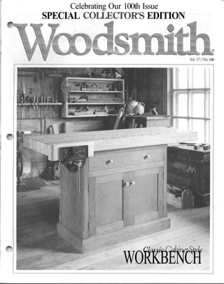
  • 1. Celebrating Our 100th Issue SPECIAL COLLECTOR'S EDITION Vol. 17/No. 100 ClassicCabinetStyk WORKBENCH
  • 2. No. 100 August, 1995 Editor Executive Editor Managing Editor AssistantEditors Creative Director Senior Illustrators Illustrator Photographer Electronic Graphics Design Director SeniorDesigner Shop Manager ShopAsst/Facilities DonaldB. Peschke DouglasL.Hicks TerryJ.Strohman Jon Garbison MarkA. Williams TedKralicek David Kreyling CindaShambaugh DirkVerSteeg Erich Lage Crayola England Chris Glowacki KenMunkel Kent Welsh Steve Curtis SteveJohnson CIRCULATION Sw6serijotionMancw7ers:SandyBaum,TroyJ.Dowell, Paige Rogers • Assistant Subscription Managers: Shane Francis, Julie Greenlee • Newsstand Manager: Kent A. Buckton PUBLISHING SERVICES Mgr: Gordon Gaippe • Graph. Artist: Cheryl L. Cynor CORPORATE SERVICES Planning Director: Jon Macarthy • Controller: Robin Hutchinson 'Account.: Laura Thomas • Bookkeeping: Holly Lucas • Production Mgr.: Carol Quijano • Info. Serv. Mgr.: Joyce Moore • Elec. Pub. Coord.: Douglas M. lidster • Network Adm.: NickThielen • Admin. Assistants: Cheryl A. Scott,Julia Fish* Receptionist: Jeanne Johnson • Build. Maint: Ken Griffith WOODSMITH MAIL ORDER Art Dir.: Cindy Jackson • Catalog Prod. Mgr.: Bob Baker • Inv. Control/Prod. Mgr.: Mark Mattiussi • Proj. Supplies: LindaJones • Tech. Supp: Dave Stone • System Operator: Tammy Aldini CUSTOMER SERVICE Manager: Jennie Enos'Team Leader: Karla Cronin • Customer Service Reps.: Jennifer Murphy, Joy Krause, Sara Kono, Anna Cox, Lonnie Algreen, Adam Best, Kristi Andrews SHIPPING DEPARTMENT Supr: Nancy Johnson • Fulfillment Gloria Sheehan, Chuck Carlson, Sylvia Carey, Larry Prine WOODSMITH STORE Manager: Dave Larson • Assistant Manager: Paul Schneider»Sa£es Staff: Wendell Stone, Pat Lowery • Office Manager: Vicki Edwards Woodsmith® (ISSN 0164-4114) is published bimonthly (Feb., Apr., June, Aug., Oct., Dec.) by Woodsmith Corp., 2200Grand,DesMoines,IA50312. Woodsmith® is a registered trademark of Woodsmith Corp. Copyright© 1995 WoodsmithCorporation.Allrightsreserved. Subscriptions: Single copy: $3.95. One year subscription (6 issues), $19.95. Two years (12 issues), $35.95. (Canada/For- eign add $5 peryear, U.S. funds.) Second Class Postage PaidatDes Moines, IAandataddi- tional offices. Postmaster: Send change of address to Woodsmith, Box 10718, DesMoines, IA50350. Subscription Questions?Call 1-800-333-5075, 8:00am to 5:00pm, CentralTune,weekdays. E-Mail. Prodigy: EDJE97A, CompuServe: 75330,2301, Internet 75330.2301@compuserve.com.,AmericaOnline:Donpeschke. Printed in U.S.A. E D I T O R ' S C O L U M N Sawdust It's still hard to believe that this is the 100th issue of Woodsmith. To me, it just doesn't seem that long ago that I was working on the first issue. I guess time does flywhenyou're havingfun. READERS' GALLERY. To help celebrate our 100th issue, I wanted to do something special. Something a little different. So a couple issues back I asked readers to send in photographs of Woodsmith pro- jects they had built. To say that I was pleased with the response would be an un- derstatement. I can't remember the last time I had so much fun opening the mail. Every daywe received dozens ofentries. (There's one day's worth shown at the bot- tom of this page.) And every day I was im- pressed by the quality and variety of the projects being built. But best of all, it didn't seem to matter if a person had been a woodworker for 22 years (like Mary Ellen Hampton), or they were building their first woodworking pro- ject. All of them seemed to share a genuine love of woodworking. And that's some- thing I'm proud to be part of. All in all, we received hundreds ofphoto- graphs. Many more than we could ever hope to put on two pages. So we picked photos that represented a wide variety of Woodsmith projects. Congratulations to those people whose projects appear on pages 16 and 17. And to everyonewho sub- mitted photos — thank you. The Readers' Gallery isn't the only thing special about this issue. We've also in- cluded three special projects. CLASSICWORKBENCH. The last time we featured a traditional workbench was in Woodsmith issue No. 50. But this time, in- stead of a "European-style" bench with an open base, we took a different approach. We designed a classic cabinet style workbench. (It reminds me of the kind of bench you might have seen in a turn-of- the-century woodworking shop.) Besides offering plenty of storage for various tools and accessories, this bench also features a solid maple top. And an easy to install, bolt-on woodworking vise. As I said before, this bench has an old fashioned feelto it. So we wanted to photo- graph it in an old fashioned setting (see the photos on the front and back covers). The trick was finding the right setting. But we found it right here in Des Moines: the woodshopatLivingHistoryFarms. (Living History Farms is an open air museum that tells the story of Midwestern agricultural and rural life.) DOVETAIL CHEST. The other "old fash- ioned" project in this issue is the dovetail chest on page 18. It features traditional hand-cut joinery and a shellac finish. THREE-BOARD SHELF. Also, check OUt the three-board shelf on page 28. It's a sim- ple weekend project with a unique mount- ingsystem. Woodsmith No. 100
  • 3. A L O O K I N S I D E Contents FEATURES Classic Workbench . . . . . . . . . . . . . . . . . . . . . . . . . . . . . 6 Sturdy and solid — nothing on this workbench is fragile. Even the metal visefeatures heavy wooden jaws, so it has a wide clamping surface and holds a pair of bench dogs. Laminated Top.................................... 14 There are two tricks to building aflat laminated bench top: laying out the boards properly and gluing them up. We've included some tips, techniques, and a simple jig for making this process as easy and accurate as possible. Readers* Gallery.................................. 16 Many readers responded to our requestfor snapshots ofthe projects they've builtfrom past issues. Here's your chance to see the work ofsomefellow woodworkers. Dovetail Chest.....................................18 This heirloom chest isjust a box with a lid — and a sliding tray inside. It'll give you a chance to use some traditional woodworking techniques and an old-fashionedfinish. Hand-Cut Dovetails 24 Ifyou've never cut dovetails by hand (or ifyou need a quick "refresher course"), here's our simple step-by-step method. Three Board Shelf 28 Nothing fancy here, just three boards. But don't miss the unique hanging system. About all you needfor this project is a boardfoot of lumber and an evening to build it. Tips & Techniques............................... 4 ShopNotes 30 Sources................................................ 31 Classic Workbench page 6 -•**, Dovetail Chest page 18 Hand-Cut Dovetails Three Board Shelf page 28 No. 100 Woodsmith
  • 4. "7T F R O M F E L L O W W O O D W O R K E R S Tips &Techniques SANDER CONVERSION • Sanding in tight places is about as much fun as doing taxes. You could buy an expen- sive detail sander (the kind with a triangle-shaped head), but in- stead I converted my finishing sander into one. It's easy to do. Just change bases. Simply remove the screws and take offthe oldpad. Then use it as a template to mark the mounting holes for a new base. But here's the best part. You can make a new base fit any shapeyou want. This new base can be made from almost any thin material. But I like V4"-thick Masonite. The self-adhesive sandpaper I use seems to stick better. Jace Laakso Missoula, Montana Remove existing base and install auxiliary base * Masonite base Cut base to any shape you need 45° CORNER CLAMP • I was recently working on a displaycabinetwith a glassfront built at a 45° angle Qike a bay window). The problem was try- ing to clamp and glue the front frame pieces together. That's because the frame pieces were ripped at 22^° (halfof45°). My solution was a two-piece clamping jig. There's a base piece with an opening cutin itto match the angle ofthe miter, see drawing below. It cradles the workpiece and keeps it from moving. A clamping block on top pushes the workpiece down against the angled base. That way when the clamp is tight- ened the mitered pieces are squeezed tight together. Orville Heitkamp Belle Plaine, Minnesota Base cradles workpiece while clamping block ROUTER FENCE INSERTS • I need a large opening (for clearance) in my router table fencewhenusinglargebits. But a large opening isn't safe when routing small pieces— they can wedge between the bit and fence causing kickback. Tosolvethisproblem,Iadded a replaceable insertto myfence. Itfills in the space around the bit so small pieceswon'tgetcaught in the opening. To make an insert for your fence, simply rout a shallow mortise Qike the mortise for a hinge) around the opening, see Fig. 1. It's cut a little larger than needed forthewoodscrews that hold it in place. And just deep enoughtoequalthethicknessof the insert. (I used a V8"-thick piece of Masonite.) I make an insert for each bit. For a straight bit, simply raise it in the router table and cut out the insert, see Fig. 2. But for profile bits, the bear- ing gets in the way. So first cut a clearance slot in the insert, and then cut the profile, see Fig. 3. Mark Muncie Indianapolis, Indiana 1 Cut insert to cover opening in fence Router table fence For straight bits, simply raise the bit to cut a slot Insert t Straight ~" bit FIRST: Cut out slot for bearing clearance SECOND: Raise profile bit to cut insert to the same shape Insert Profile bit Woodsmith No. 100
  • 5. BAND CLAMP BLOCKS • I like to use a band clamp and corner blocks to glue-up mi- tered pieces. But on many blocks, the strap "hangs-up" on a sharp outside corner. So I made a set ofcorner blocks with a rounded outside edge. You cut all four blocks from a IW-thick blank, see Fig. 1. But it's easier to do most of your work on the blockswhile they're still part ofthe blank. First, lay out all of your cuts. Then make a partial saw cut on all four sides to define the block size, see Fig. 1. The diameter can be cut next on the band saw and sanded smooth.Then drill a 1/4"dia.clearanceholeineachof the blocks. Next, a shallow groove is routed around the outer edge to hold the strap, see Fig. 2. A tall fence supports the work- piecewhen rolling itpastthebit. And aMasonitebase covers the hole in the tabletop so the work- piece won't drop into it. Now cut the blank into four blocks. To do that, first band saw the pieces apart, see Fig. 3. Thenusethetable sawto cutthe inside corners exactly 90°. Mark Routzahn Tiffin, Ohio FIRST: Make partial cuts to divide blank into four sections Usebandsaw to cut out blocksRoll workpiece past bit to make groove Saw between kerfs Tall auxiliary fence Wdiameter > clearance hole Rotate block 90° to make second cut Va" Masonite auxiliary base SECOND: Cut out circle and drill clearance holes QUICK TIP • Clamp pads can prevent a lot of dents. But instead of buyingthem, Imakemyown. These pads are cut from sheets ofheavy duty felt avail- able atmost hardware stores. Self-adhesive backing holds them on the clamp jaws. Ed Flietner Phillips, Wisconsin SILL COCK KNOBS • A quick replacement for large plastic knobs, like you'd find on a router table, is a carriage bolt and a sill cock handle (the metal handle from a water spigot), see Fig. 1. Both are available at local hardware stores. Sill cock handle and carnage bolt replaces studded knob Simply insert a Vi" carriage bolt in the handle and add a nut and washer, see Fig. 2. The square shank on the bolt, fits the opening in the handle perfectly. Gary Adler Gassville, Arkansas SUBMIT YOUR TIPS If you would like to share an original shop-tested tip, send it to Woodsmith, Tips and Techniques, 2200 Grand Avenue, Des Moines, Iowa 50312. Orifit'seasierforyou, FAXitto us at: 515-282-6741. E-Mail: 75330,2301@com- puserve.com. If we publish it, we will sendyou$30to$150,depend- ing on the published length. Include a brief explanation and sketch (or photo). And don't worry, we'll rewrite the tip and redraw the art if nec- essary. Also, please include a daytime phone number. No. 100 Woodsmith
  • 6. F E A T U R E P R O J E C T Class& Workbench The base of this workbench does more than support the top. The trays and drawer store a shop's worth of tools — within easy reach. ost shops can always use more storage space. So why not build a workbench where the base not only supports the top but also provides space inside for your hand and power tools? That's the idea behind this workbench. And to make it easy to use this storage space, a drawer and two trays ride on full-extension slides to keep your tools accessible. Then there's thetop.Thislaminated, hard ma- ple top adds considerable weight to a storage cabinet already filled with tools. When you com- bine the two,you endupwitha"rock-solid"work- bench capable ofhandling most any project. To hold these projects on the bench, there's a metal woodworking vise attached to one corner with a thick, maple-block covering the front jaw. A pair of dog holes in the block line up with the holesinthebenchtop so bench dogs canbe used to hold bigprojects.And thevise is easyto install. Just four lag screws hold it in place. Woodsmith No. 100
  • 7. Construction Details Record #52'/2 ED vise withquick-release mechanism Made from strips of 8/4 hard maple glued face-to-face BASE: Outside case is made from cherry hardwood and plywood Interior framing and drawers made from maple hardwood and plywood NOTE: Complete cutting diagram and materials list on page 13 CROSS SECTION END VIEW ———— 22%" ————— Drawer wood knobs Frame and panel doors Hardwood kickboard _ Ball catch for doors Note: Drawer and trays are mounted with full- extension drawer slides Trays- VISE DETAIL CROSS SECTION Solid steel handle The Record #52V2 ED vise with woodjaws has an open capacity of 9%" Frame and panel back - 19V2"- Wood spacer _ Quick-release lever allows ^- Vise mounted with (4) vise to open and close freely V2" x 3" lag screws HARDWARE LIST • (1) Record #52V2 ED Vise • (2)#14x2" RhWoodscrews • (4) 1/2" x 3" Lag Screws . (4) 1/2" Washers • (4) 1V4"-dia. Wood Knobs • (2pr.)2" x13 /s" Ball-tipped Hinges • (2) Ball Catches (8) #4 x 1/2" Fh Woodscrews (4) 1/4" x 3" Lag Screws (4)V4" Washers (20) #8 x 13/4" Fh Woodscrews (36) #8 x 11/4" Fh Woodscrews (16) #8 x 1" Fh Woodscrews (3 pr.) 16" Full-Extension Drawer Slides No. 100 Woodsmith
  • 8. apairofcase sides (J)arecutnext,seeFig. 2.These arejust3 /4M -thickpieces ofplywood with 3 /8M rabbets cut on both edges. Each rabbet forms a tongue that fits into the grooves alreadycutin the stiles, see Fig. 2a. Then assemble the sides and frames and glue and clamp the case together. After tightening your clamps, checkthatthe case remains square. CHAMFER STILES. With the case assem- bled, I routed a decorative stopped chamfer on all four corners, see Fig. 3. (Itworks best to rout this chamfer in several passes.) CLEATS. Next, I turned my attention to the inside ofthe case, starting atthe bottom and working my way up. First, I cut a pair of front/back cleats (K)andapairofsidecleats(L)tofitinside the case, see Fig. 4. These cleats are posi- tioned so the case bottom (added next) will fit flush with the top edge of the bottom rail on the front frame, see Fig. 4a. BOTTOM. After the cleats are installed, thecase bottom (M) canbe cutto size, see Fig. 4. This piece of V£"-thick plywood rests on the cleats and helps strengthen the cabi- net when it's glued and screwed in place. STIFFENERS. On most projects, I'd be fin- ished with the cabinet once the bottom was installed. Butnothere. Instead, to make the case stronger, I added frame stiffeners. These W-thick pieces of maple cover the joint lines on the frames. It's an easy way to strengthen the stub tenon joints. I started by cutting three horizontal stiffeners (N) tofitinside the case, see Fig. 5. Two fit behind the top rails on the front frame, while the third is glued to the top rail of the back frame, see Fig. 5a. Next, I addedvertical stiffeners. First, the vertical stiffeners (O) are glued and screwed to thebacktwo corners ofthe case CROSS SECTION CASE BOTTOM (%" plywood) Fh I woodscrew #8x1%"Fh woodscrew NOTE: Bottom fits flush with top of rail NOTE: Cleats cut from %"- thick stock -<K) CLEAT (I'A'-wide) HORIZONTAL STIFFENER^ (%'x 2'x 34W) la CROSS SECTION Stiffeners glued ! to rails to strengthen frame NOTE: i Glue stiffeners in place between the horizontal stiffener and case bottom, see Figs. 6 and 6a. The other ver- tical stiffeners (P) and (Q) fit along the sides of the drawer and door openings and are glued and clamped to the front frame. MOUNTING CLEATS. Now to hold the top in place later, I added a pair of mounting cleats (R). These are just 3 /4"-thick pieces of stock glued and screwed flush with the top ofthe case sides, see Figs. 6 and 6b. KICKBOARD. To complete the case, all that's left is to install a kickboard. First, I cutthe stockto finishedwidth (4") with a V£" chamfer routed along the top edge. Then the front/back kickboards (S) and side kickboards (T) are mitered to fit around the base and are glued and screwed in place, see Figs. 7 and 7a. MOUNTING R)Ci£A7 VERTICAL STIFFENER NOTE: Glue and screw stiffeners to backs of stiles O. CROSS SECTION (TOP VIEW) K. l_KUii iCtllUIH (SIDE VIEW) #8x 13 /4" Fh woodscrt ^ ^ V-N •«-7!4-*- w f^ iltl ft fi? ^ l l a. CROSS SECTION (SIDEVIEW) Miter kickboards to fit around case No. 100 Woodsmith
  • 9. DRAWER, TRAYS, & DOORS Once the outside ofthe case was finished, I turned my attention to the inside to add a pair of trays and a drawer. CLEATS. Iplanned on usingfull-extension slides for the drawer and trays. But the slides couldn't be screwed to the case sides because the frame stiffeners got in the way. So I added slide cleats (U) to provide a mounting surface for the slides, see Fig. 8. These cleats are3 /4M -thick pieces of stock screwed to the frame stiffeners. They don't extend all the way to the front of the case, otherwise the doors and drawer wouldn't close all the way, see Fig. 8a. To get the needed clearance, I installed the cleats Vie" back from the inside face ofthe front frame. TRAYS. With the cleats installed in the case, I began workon the trays. Idecidedto use pull-out trays because it makes it a lot easier to get at your tools — especially the ones at the back. To determine the size of the front/back tray pieces, first measure the opening be- tween the cleats (mine was SOVfe"). Then subtract 1" for the thickness of two slides and Vfe" forthelapjointsatthecorners. Find- ing the size of the tray sides is easier. It matches the length ofyour slides (16"). I used these measurements to cut the trayfront/back(V) andsides (W)tofin- ished size, see Fig. 9. (My tray was 16" x 29W.) Next, I cut a 3/4"-wide rabbet atboth ends ofthe sidesforlapjoints tojoin the tray pieces together, see Fig. 9a. Then a groove can be routed on the inside face of all the tray pieces to hold a W-thick piece of ply- CROSS SECTION (SIDE VIEW) ® SLIDE CLEAT NOTE: Install cleats and slides VK" from front frame Screw cleats to vertical stiffeners 16" full- extension drawer slide NOTE: Slides mount to cleats with screws wood for a bottom, see Fig. 9b. Makingthetraybottom (X)fromWply- wood keeps it from sagging when loaded with tools. It should fit snug in the tray pieces before you glue the tray together. DRAWER. With the trays complete, the drawerisbuiltnext. What's differentis how the drawer is held together. It has hand-cut dovetails for strength and durability. Here again, you want to measure the opening before making any cuts. Then cut the drawerfront/back (Y) and sides (Z) to finished size and lay outand cutthe dove tails, see Figs. 10 and lOa. Formore on cut- ting dovetails, refer to page 24. Nowroutagroovetoacceptadrawerbot- tom, see Fig. lOb. Once again, I used VzH - thickplywoodforadded strength.Thencut the bottom (AA) to fit tight and glue and clamp the drawer together. TRAY SIDE TRAY FRONT a. SIDE V2" TOP VIEW ' FRONT/BACK- END VIEW Size groove to match plywood v / J~ L^' I I 10 Woodsmith No. 100
  • 10. You'll probably notice the groove cut for the drawer bottom is still visible on the drawer front. But don't worry about it. It'll be hidden by a false front added later. SLIDE INSTALLATION. After the drawer and trays are complete, the next step is to install the full-extension drawer slides. I used a pair of 16" slides for the drawer and each tray. (To find sources forthe hardware you need to build this bench, see page 31.) Basically, installing the slides is a two- step process. First, one half of the slide is screwed to the slide cleat in the case, see Fig. 8. Then the other halfis mounted to the drawer or tray, see Figs. 11 and lla. FALSEFRONT. With the drawer installed in the case, a false front (BB) is added next. This is just a 3 /4M -thick piece of stock that fits in the case with a Vie" clearance all around, see Fig. 12. Before screwing the false front to the drawer, I drilled a pair of V2"-dia. holes for some wood knobs. Then install the false front, keeping the needed clearance around the drawer and glue the knobs in the holes. DOORS The last thing to add to the cabinet is a set of doors. The unique thing about these doors is they're cut to fit tight first — then trimmed for clearance later. The goal here is to have a Vie" clearance on the top, bottom, and along the sides of the doors, see Fig. 14. You also need the same clearance (Vie") between the doors in the middle. So I measured the opening in the frame first (19Vs" x 32") and then cutthe 16" full- extension drawer slide NOTE: Center of slide aligns with layout fine Exposedgroove will be hidden by false front Maintain Vie gap around arawer stiles (CC) and rails (DD) f or a tight fit, see Fig. 13. But remember to allow for the ten- ons when cutting the rails to length. Note: Later, after the doors are assembled you can trim them for the Vie" clearance. Next, a groove is routed in all the frame pieces to match the thickness ofthe center panel, see Fig. 13a. And to hold the frame together, tenons are cut on the ends of the rails to fit snug in the grooves, see Fig. 13b. Thenadoorpanel (EE)iscuttofitineach frame before gluing the door together. Now a pair of hinges can be installed on each door by mortising them into the front frame and door stiles, see Figs. 13 and 14. Here, I used acouple pennies for spacers to hold the door in position while installing the hinges, see Figs. 14a and 14b. Finally, to complete the doors, a pair of knobs is attached to the door stiles. And a pair ofball catches is installed in the cabinet to hold the doors closed. Center 1W-dia knob on width of door stile, see Fig. 13. NOTE: Keep a ' clearance around doors, see detaila. fb - s (T< x '> V J 1_* 1 = f- • CROSS j ECTION M> VIEW) ', '• / ^/P P K /' ^————, i Mortise hinge DOOR int0 D0th door STILE anci front frame No. 100 Woodsmith 11
  • 11. BENCH TOP After the cabinet is complete, I worked on the bench top next. Note: For more on building lami- nated tops, refer to page 14. STRIPS. This laminated top consists of 13 bench top strips (FF). These strips are l3/4"-thick pieces of stock cut to a finished lengthof62"andaroughwidthof 39 /i6". Later, the top is sanded to its final thickness (3W), see ex- ploded view at right. ALIGNMENTHOLES. To keep all the strips aligned when gluing them together, I drilled holes for short lengths of ^"-dia. dowels, see detail 'a.' But remember, the two outside strips (1 and 13) only have holes on one face. DOGHOLES. You could glue the bench top strips together now. But I didn't want to wrestle with a heavy top. And there are still a few things left to do. First, a series of 3 /4"-dia. dog holes are drilled in the top for bench dogs, see detail 'b.' Referto page 31 for sources of bench dogs. Then rout a Vs" chamfer around each hole to soften the sharp edges. ROUNDOVER. Next, the corners on the two outside strips are rounded over, see de- tail 'c.' Note: But don't round the corner at the end where the vise will be mounted. NOTCH. There's one more thing to do be- fore gluing the top together. And that's to routapocket in the front strip for mounting a metal vise. The back jaw of the vise slips into this pocket. This way, the metaljaw is CROSS SECTION (BENCH STRIPS) c. CORNER DETAIL BENCH TOP STRIP J CROSS SECTION (FACE BLOCK) U CROSS SECTION (BENCH STRIPS) ft'-dia. dog hole Sana to final thickness of 3Vi covered by the front strip, and you have a long, smooth surface to clamp against, see Figs. 15 and 18. GLUE-UP. With the pocket routed, the bench top strips can be glued together, see Fig. 16. Later, I used a belt sander to sand the top and bottom faces smooth. BENCHTOP INSTALLATION. Once the top is sanded, it can be attached to the cabinet. Butfirst I routed an Vs" chamfer around the bottom edge, see Fig. 17. Then position the top so it's centered side to side with a IVi" overhang on the back, see Fig. 17a. Now drill shank holes through the cleats in the cabinet and use 3" lag screwswith washers to hold the bench top in place. VISE With the top secured to the cabinet, thevise can be installed next. I used a Record vise, 15 Rout pocfcet in bench strip for vise jaw 9Vis" CROSS SECTION n Topedge Front strip (Ato.7.) I Do not use alignment dowels in first two holes 17 Laminated Top FRONT VIEW Install top so it's centered side-to-side on cabinet NOTE: Before mounting top to base rout Vs" chamfer around bottom edges CROSS SECTION '-*' (SIDE VIEW) chamfer-^ washer ~- VA" x 3" lag screw 12 Woodsmith No. 100
  • 12. model #521^ ED. It features a quick-release on the frontjaw, so it can be moved in or out with the touch of a lever. VISEINSTALLATION. But before installing the vise, I added a spacer block (GG) to make the top ofthe face block (added next) level with the bench top. This 3 /4"-thick piece of stock is cut to match the mounting plate on the vise (in my case 5" x 9"). Then drill VS"-dia. mounting holes through the spacer block and screw the block and vise to the bench top, see Fig. 18. FACE BLOCK. After installing the vise, I covered the front jaw with a thick maple block. This block protects your workpiece and also spreads the clamping pressure over a larger area. To make the face block (HH), glue to- gether a couple pieces of stock to create a 2W-thick laminated piece, see exploded viewand detail 'd' onpage 12.Then drilltwo 3 /4M -dia. dog holes in the face block and round over the two outside corners. Now rout a Vs" chamfer on the bottom edge and attach the face block to the vise, see Fig. 18. To complete thebench top, I used ahand- held router to rout a Vfe" chamfer on the top edge (including the vise), see Fig. 19. It re- moves the sharp edge left over from sand- ing the top smooth. Q Rout Vs" chamfer around top edges NOTE: Chamfer top edge of face block with vise closed MATERIALS LIST CUTTING DIAGRAM CASE Case Bottom (1) A B C D E F G H I J K L M N O P Q R S T U Slide Cleats (6) V Tray Fr./Bk. (4) W Tray Sides (4) X Tray Bottoms (2) Y Dr. Fr./Bk. (2) Z Dr. Sides (2) 3/4x2-32V5 3/4 X 2 - 323/4 3/4 X 67 /8 - 323/4 3/4 X 3 - 243/8 V4ply. - 15V4X243/8 3/4X2-32V5 Bk. Stiles (2) Bk. Upper Rail (1) Lower Rail (1) Center divider (1) Back Panels (2) Fr. Stiles (2) Fr. Upper Rails (2) 3/4 x 2 - 323/4 Fr. Lower Rail (1) 3 /4 x 43/8 . 323/4 Filler Strips (1) Case Sides (2) Fr./Bk. Cleats (2) Side Cleats (2) 1 /4 x 3/8 - 60 (rgh) 3/4 ply. -171/4X32V5 3/4 X 1 V4 - 341/i 3 / 4 X 1 V 4 - 1 4 1/2 ply. -16V2 x 341/5 Hor. Stiffeners (3) 3/4 x 2 - 34V2 Vert. Stiffeners (2) 3 /4 x 11/4 - 28Vs (rgh) Vert. Stiffeners (2) % x 1V4 - 5V5 (rgh) Vert. Stiffeners (2) 3/4 x 1V4 -191/5 (rgh) Mntg. Cleats (2) 3/4x1V4-15 Fr./Bk Kickbrds. (2)3/4 x 4 - 37V5 Side Kickbrds. (2) 3/4 X 4-19Vi 3/4X13/4-161/2 3/4X13/4-29 3/4X13/J-16 1/2 ply. -15'/4 x 283/4 3/4 X 43/8 - 29V2 3/4X43/8-16 AA Dr. Bottom (1) V2 ply. - 151/4 x 283/4 BB Dr. False Fr. (1) 3/4 x 47/3 .317/3 CC Door Stiles (4) 3/4 x 21/5 -19Vs DD Door Rails (4) 3/4 x 2 Vs - 113/4 EE Door Panels (2) 1/4 ply. -113 /4 x 14% BENCH TOP FF Bench. Strips (13) 13/4X39/16 - 62 GG Spacer Block (1) 3/4 x 5 . g HH Face Block (1) 2V2X4V8-14 %" x 9"- 96" Cherry ( 6 Bd. Ft.) T T S — S -7 B '' '/ G /// G /.'/ /// / /. '/'// / /' / // / /// %" x 7"- 96" Maple (4.7 Bd. Ft.) —————— N———————— ————— w—————— ——————————O——— ———u——————u I 0 ! /^ f / u —— Y/////-, — . .. .. . . V /•//// %"x4"-96" Maple ( 2.7 Bd. Ft.) ^ —— — - ' ———————V————————— ——————— V ———————— ——— W ——— ——— W ———— '/' / / 1 %" x 6"- 96" Maple (4 Bd. Ft) Y L 1 L Y I ft I ft 2 Z //, K ' V %" x 5"- 72" Cherry (2.5 Bd. Ft.) A A F F ' // / '/ / / V x 7"- 72" Cherry (3.5 Bd. Ft) C BB K %" x 5"- 72" Cherry (2.5 Bd. Ft.) •/.,,?»,,.,% %"x6"- 72" Cherry (3 Bd. Ft.) CC CC 1%"x5"- 96" Maple (6.7 Bd. CC DD DD CC DD DD Ft.) FF l%"x8"-72" Maple (6boards@ 7.5Bd. Ft. ea.) FF FF //// ALSO NEED: '/// Vt"x48"x48" Vi' x 48" x 48" / ///, •'/, Maple plywood 3 /n" x48" x48" Cherry plywood '// // HH HH X^ GG •- ^N %" thickness ''/'/' / /' 3 A" thickness No. 100 Woodsmith 13
  • 13. W O O D W O R K I N G T E C H N I Q U E Laminated Top Building a laminated top may seem a little intimidating at first. You have a lot of boards to cut and fit together. But you don't have to be a magician to get a solid, tight-fitting top if you know a few tricks. It only takes two steps: laying outthe boards so they're compatible with each other and gluing them together to avoid any gaps. LAYOUT Like drawing and discarding playing cards to get a better hand, the boards in a laminated top need to be sorted for the best fit and appearance. This means checking each piece for crook and bow but also arrang- ingtheworkpiecessothetoplooksitsbest. CROOK. The maple boards I used all had a little crook and bow. But when trying to assemble a laminated top, the crook of a board can cause you more trouble than its bow. So I checked for crook first. Crook is warpage across the width of a board running from end-to-end, see Fig. 1 and the Shop Tip below. It can be difficult to "pull" a crooked board straight. So do you discard all the boards with crook? Well, if there'smore than Vs" ofcrook, I'll cutitinto shorter pieces for another project. Boards with less than Vfc" ofcrook can be used — if they've been sorted first. I ar- range them so the crooks oppose each other, see Fig. 1. This way when the pieces are forced flat, the crook is canceled. To keep track of the direction, I'll mark an arrow on the board pointing to the crook. BOW.Whenyou'veidentified the crook, you can sort the boardsto minimize bow. Bowis warpage along the edge from end-to-end, see Fig. 2. Unlike crookedboards, you can usually pull a bowed board straight. That's because you're straight- ening the board across its thick- ness (not across the width). Here again, arrange your boards so the "bows" oppose each other. I'll put my straight- estboards ontheoutsideto help pullthe rest ofthe bowed pieces straight. Note: While rearrang- ing the boards for bow, remem- ber to keep the crooks opposed. APPEARANCE.Withthepiecessortedfor crook and bow, you still need to consider how the boards will look when glued to- gether. Small blemishes will be sanded out when the top is leveled. But for larger de- fects you should shuffle the boards again. LABELPIECES. Onceyouhavetheboards arranged for crook, bow, and appearance, Arrows point to crook of board Arrange pieces so the crook of the board alternates Arrange boards so bowed faces oppose each other Place the straightest boards on the outside SHOP TIP Gap between string and workpiece shows crook Howmuch crook is there? It's not always easy to tell. A simple way to measure crook is to use a string and some tape. Just stretch the string from end-to- end and tape it in place. Then at the center measure the gap be- tween the string and the board. Dry clamp the pieces together to check the fit Arrow points to face that fits in jig -^ 14 Woodsmith No. 100
  • 14. C E L E B R A T I N G O N E H U N D R E D I S S U E S O 1 Readers' Gallery Over the years, a lot ofreaders have sent us photos of projects they've built from Woodsmith. Plus, we've received hundreds more since I announced this gallery in the Sawdust column a couple ofissues ago. Of course, we couldn't include every photo. What you see here is a sampling of the crafts- manship andingenuityofourreaders. Somefol- lowed our plans closely; others adapted them quite a bit. We hope you enjoy seeing these completed projects as much as we have. Classic Workbench (Issue 50) Donald Jacoby Arvada, Colorado Oak Rocking Chair (Issue 84) TomBaker San Diego, California Editor's Note: Tom used black walnut to build his oak rocker. Saw Cabinet (Issue 47) David Kerski Eden Prairie, Minnesota "This photo was taken in my library because my shop was too small." Regulator Clock (Issue36) Chris Hellmuth Middle Island, New York Armoire (Issue 67) Armoire (Issue 67) Bill Evans Bob Schuchard Rehoboth, Massachusetts Fort Collins, Colorado Editor's Note: Most readers customize ourprojects to some extent. Bill Euan's cherry armoire looksjust like ours but has drawers inside. Bob Schuchard's pine armoire has a scalloped base and raised panels on the sides. Pedestal Desk (Issue 79) R. E. Corbett, Jr. Wilmington, North Carolina "This is the only piece offurniture in our house that both children have requested when I die." Classic Roadster (Issue51) Frank Pino Edwardsville, Kansas Garden Bench (Issue 93) Bill Kilpatrick Enniskerry, County Wicklow, Ireland Rocking Horse (Issue 65) William Murray London, Ontario 16 Woodsmith No. 100
  • 15. W O O D S M I T H W O O D W O R K I N G P R O J E C T S Heirloom Cradle (Issue 48) Robert Kubiak Omro, Wisconsin Curved-Front Table (Issue 77) Mark Hoecker Charlotte, North Carolina Oak Icebox (Issue 36) RonAnderson Atlanta, Georgia "I'm brand new to woodworking. My wife complains about never seeing me anymore, but after seeing my first results, she has slacked offa little." ill Tall Case Clock (Issue70) Steve Hart West Linn, Oregon Country Coat Rack (Issue 86) | BobWhite Muskegon, Michigan SewingBox (Issue 78) James Stephens Ladson, South Carolina "I used old pine pallets for the wood to build thissewingbox." Country Pie Safe (Issue 55) John Zelenak Toms River, New Jersey Blanket Chest (Issue 32) Jack Couch Pinson, Tennessee Porch Swing-Glider (Issue 39) James Galluzi Poughkeepsie, NewYork Country Hutch (Issue 96) Bud Migues Penn Valley, California "Antiquing this hutch took seven different finishes." Ladder-Back Chairs (Issue 64) LloydArundale Ridge, New York "The dining room chairs were the most challenging. I started with six and ended up with five." No. 100 Woodsmith 17
  • 16. H E I R L O O M P R O J E C T Dovetail Chest The charm of this small chest is created with two "old" woodworking techniques: cutting dovetails by hand and brushing on a few coats of shellac. You don't want to rush hand-cut dovetails. Theyrequire careful, deliberate work.That doesn't mean they have to be perfect. After all, hand-cut dovetails aren't going to be machine- precise — especially with wide panels. But that fits the charm of this chest perfectly. There's something to be said for a few quiet hours in the shop. Working withoutthe roar ofa router or breathing the clouds of dust. Okay, so the pace is alittle slower, and theprocesstakes a little longer. This is one time to throw out the schedule. If you can put yourself in the right frame of mind, the process is its own reward. Come to think of it, applying the finish to this chest is rewarding too. I wanted it to match the "antique"characterofthe chest. Andwhatbetter way than to use an "antique" finish? Shellac has been used on furniture a long time, and its color adds a natural warmth that's hard to get from an off-the-shelf stain. Ofcourse, manywoodworkers think ofshellac as a "delicate" finish. And while it may not match the durability of polyurethane, a lot of antiques finished with shellac have put up with years of wear. Andit's notdifficultto applyeither. Forstep- by-step instructions, see the box on page 23. 18 Woodsmith No. 100
  • 17. Overall Dimensions: 38Vs" x 79%" x 78'/s" Wood: Pine - 43 bd. ft. (See Materials list. Supplies list, and cutting diagram on page 23.) Finish: One coat of orange shellac Two coats of blonde shellac EXPLODED VIEW Wide chamfer shaped with block plane NOTE: All panels are glued up from solid wood BASE FRONT Dovetails cut by hand, see a/t/c/e on page 24 LID- BASE END Sliding Tray. Like the case, the sliding tray inside the chest isjoined with hand-cut dovetails. This tray sits on simple supports glued into thefront and back ofthe case. TRIM FRONT -Tray slides back and forth on wood supports BOTTOM- END VIEW CROSS SECTION BACK TRIM BASE No. 100 Woodsmith 19
  • 18. CASE This dovetail chest starts out just as you'd expect: gluing up oversized panels. There isn't anything unusual or difficult about these five 3 /4"-thick panels. The important thing is that they are flat and all the same thickness. This will make it much easier when it comes time to cut the dovetails. After the panels are glued up, the next step is to cut the front/back (A) and end (B) panels to finished size, see the drawing at right. (The bottom will be cut to size later.) I began by simply ripping each of these panels to width. But when crosscut- ting, the long panels require some extra support.To dothis, Iadded alongauxiliary fencetothemitergauge.Thisway,it'smuch easier to get the panels square. DOVETAILS. After the panels are cut to size, work can begin on the dovetails. The dovetailsarelaidoutSW oncenter, seeFig. 1. This allows for 3" tails and Vfe" pins. Actually, not all the pins are V£". The top one is alittle wider (1"). Butthe extrawidth iscoveredby some moldingaddedlater, see Fig. 2 and the drawing on the next page. Note: Inthearticlebeginningonpage24, there are step-by-step instructions for cut- ting dovetails by hand. GROOVES. When the dovetails are com- plete, there are some grooves to cut in the panels before you can assemble the case. The first groove, near the top, is for the tray supports. It's %" wide and cut in the front and backpanels only, see Fig. 3.1 cen- tered these grooves in one ofthe pin open- ings.Thiswaythepinsontheendswillhide the grooves when the case is assembled. The other groove is for the bottom ofthe chest, see Fig. 4. It's3 /4" wide and cut in all fourpieces. This groove cutsthrough atail, so it'll be visible from the outside when the case is first assembled. But don't worry aboutthis. Later, thegroovewillgetcovered NOTE: All case panels are glued up from3 /4"-thick stock by the molding at the bottom ofthe case. BOTTOM. Now it's time to begin work on the bottom panel. But to do this, first you need to dry assemble the case. Then you can measure the case opening for the final size ofthe bottom, see drawing above. Because the bottom is a solidwoodpanel and not plywood, it needs enough room to expandandcontractwithchangesinhumid- ity.To allowforthismovement,Icutthebot- tom (C) Vfe" smaller than the opening, see Fig. 4a. (Mine was 15W x 35Vs".) Cut 3 /s" x %" groove in case front and back only Wide pin at top is covered by trim molding later, see next page NOTE: To applypressure, clamps should be positioned over tails Cut 3 /a"-deep groove for bottom in all case pieces 20 Woodsmith No. 100
  • 19. CASEASSEMBLY. After the bottom panel isready, youcangluethecase together, see Fig. 5. (But don't use glue on the bottom.) Thistakesquiteabitoftime, so Iusedwhite glue. Itgives you a little more time to work. Whiletheglueis drying, cuttwo W-wide tray supports (D) to fit in the grooves in- side the case, see Fig. 3.This time, I wanted the glue to set up fast, so I used yellowglue. Thatway, I didn'thave toworryaboutusing clamps. Applying a little hand pressure for a minute or two was all it took. At this point, the case is essentially com- plete. But if there are pins or tails protrud- ing, you'll need to sand them flush with the sides of the case, see the Shop Tip at right. Once that's done, all that's left is to add the base and some trim molding around the top and bottom, see the drawing below. BASE. I like the wide, thick base molding I'veseenonsomeolderchests,andIwanted the base on this chest to look the same. So instead of using 3/4"-thick stock, I cut the base pieces from 1Vi6M -thick stock. Thebase front/back (E) and base ends (F) are first cut to rough length from 3"-wide blanks. Next, cut a decorative chamfer along the top edge, see Fig. 6.1 did this on the table saw with the blade angled 15°. Then to complete the base, miterthe pieces to length and glue them to the case. TRIM MOLDING. The next pieces to add are some strips of trim molding, see draw- ing below. Some of this trim will sit on top of the base molding. The rest will end up flush with the top of the case. To make the trim front/back (G) and trim ends (H), start with blanks that are W thickand 2" wide, see Fig. 7. Routacove along two edges using a W cove bit. Then two 3 /4M -wide (tall) trim pieces can be ripped from each blank. Miter the pieces to length and glue them in place. (The cove profiles should face each other.) Here again, don't Shop Tip: When using a belt sander, it's easy to round over a corner. To prevent this, clamp a scrap piece across the end. worry about attaching the molding with clamps. A little hand pressure works fine. Finally, topreventchippingtheedgeifthe chest ever gets dragged across the floor, rout a W chamfer on the bottom edges of the case and molding, see Fig. 8. Rip chamfer on top, outside edge of base blanks FIRST: Rout profile SECOND: Rip trim to size TRIM FRONT/BACK CROSS SECTION V? Rout chamfer around * bottom edges of case No. 100 Woodsmith 21
  • 20. p LID Now that the case is complete, I started work on the lid, see drawing at right. Just like the other parts ofthe case, this means you need to glue up another panel. But the thickness ofthis panelis different: it's IHe". Since you lift the lid from the edges, I wanted it to overhang the case a bit. So to determine the size of the lid (I), measure the case (including the trim) and cutthe lid panel 1" longer and wider. CHAMFER. I also wanted the lid to have the same chamfer that's around the base. Butthe panel is too longto stand on end on thetable saw. So I used ablockplane. Before planing, lay out the edges of the chamfer, see Fig. 9. Then plane down to theselines, startingwith the ends ofthelid. To avoid chipout, skewthe plane slightly so the cut shears off thin shavings. HINGES. When the chamfer is cut, mount thelidtothecase.Todothis,Iusedaspecial hinge. It has an offset barrel and doesn't re- quire a mortise, see Fig. 10. To mount the hinges, first screwthem to the case. Next, setthe lid on top ofthe case and center it side-to-side and front-to-back. Then simplytrace aroundthebarrels ofthe hingesonthebottomofthelid.Nowremove the lid and hinges. Then screw the hinges tothelidandreattachthehingestothecase. IID SUPPORTCHAIN. The last thing to do to the lid is add a 15"-long piece of brass chain to the inside of the case, see Fig. 10. This prevents the lid from dropping back. Safety Note: If children will be opening andclosingthislid,youshouldprotecttheir fingers by installing a lid support. (For sources, see page 31.) #8x% brass round head screw SHELLAC When choosing a finish for this chest, I wanted awarm, "aged" color. Butinstead of trying to mimic an old finish, I decided to use the real thing: shellac. For this chest, I applied one coat of or- ange shellac. The orange shellac gives the wood itswarmcolor— and itdoesn'tblotch like a normal stain will. But more than one coat makes the wood too dark. So to keep the color lighter but still add moreprotection,Iappliedtwomorecoatsof another "grade" of shellac: blonde shellac. (Shellac comes in several grades, see page 31.) Actually, this isn't a different type of shellac. It has just been purified more, so there's not much color. Shellac comes ready-to-use or in flakes thatmustbe dissolved in alcohol. (See page 31, for sources.) Once dissolved, it begins to slowlydeteriorate. So, Iusetheflakes and mix my own. This way, Iknow it's fresh. Though any alcohol will work, I dissolve shellac in denatured alcohol. Shellac is mixed in "pound cuts" — the number of pounds of flakes to a gallon of alcohol. For thischestIused a2 Ib. cut. ButIonlymixed upapintofeachgrade (whichrequires4 oz. ofshellacflakes).Anddon'tworryaboutbe- ing precise. Just get it in the ballpark. Shellac doesn't dissolve like Kool-Aid. It takesseveralhoursormore. Pourtheflakes into a non-metal container. (The shellac re- acts to metal.) Then pour in the alcohol and stir it. Let it set a bit Then stir it again. It's agood idea to strain the shellac afewtimes before using it, see photo. Before applying the first coat of shellac, I sanded the dovetail chest to 220-grit be- cause the soft grain of pine tends to raise when shellac is applied. To apply shellac, I use a natural bristle brush. The only trick is not to work the fin- ish too much with the brush. The shellac dries fast, so you can apply another coat af- ter about three hours. Note: If the shellac seems to be drying too quickly, then thin it a little with more alcohol. I sandedthe firstcoat lightly with 400-grit paper. Then after the two coats of blonde shellacwere applied, I rubbed outthefinish with 600-gritpaper. 22 Woodsmith No. 100
  • 21. TRAY Withthelidattached,thelaststepistobuild atraythatfitsinside the case and slides back and forth on the tray supports. First, the tray front/back (J) and tray ends (K) are cut to finished size. Then to join all the pieces ofthe tray, I cut the dove- tails by hand — just like the case, see Fig. 11 and the drawing at right. Next, I cut a W-wide groove %" deep in each piece for the tray bottom, see Fig. 12. The bottom is another solid wood panel. Thistime, it'sgluedupfrom ^"-thickstock, see drawing at right. When the tray bottom (L) has been glued up, I cut it to finished size. The panel should fit inside the tray (including the grooves) minus Vfe". Of course, a VS"-thick panel won't fit into a W groove. But I cut a rabbetalongthebottomedge ofthetraybot- tom to create a Vi" tongue, see Fig. 12. Next, I wanted to add some "handles" to the ends ofthe tray. These handles are sim- ply slots drilled and cut in the end pieces, see Fig. 13. To do this, first drill l"-dia. holes to establish the length of the handle slot. Then clean out the waste with a sabre saw. Nowsandthemandroutasmallchamferon both the inside and outside edges. Then the tray can be glued together. With the tray assembled, there are two steps left. First you want to chamfer the in- sideandoutsideedgessothereareno sharp corners, see drawing above right. And fi- nally, don't forget to plug the holes in the endpiecesthatwerecreatedbythegrooves for the tray bottom, see Fig. 14. Q TRAY BACK TRAY END Va" chamferon inside and outside edges of tray TRAY BOTTOM '/2"x13'/2"x231 A' TRAY FRONT 11 L_ 2V2- 0TRAY FRONT/BACK 12 TRAY BOTTOM k }, „ NOTE: Cut tray/s bottom Va'smaller than groove opening W chamfer on inside and outside edges MATERIALS SUPPLIES A Front/Back (2) B Ends (2) C Bottom (1) D Tray Supports (2) E Base Front/Back (2) F Base Ends (2) 3/4X18V*-36 3/4x181/4-16 3/4X3/8-; 1 Vie x 3 - 40 rgh. 1Vi6 x3 -20 rgh. G Trim Front/Back (4) H Trim Ends (4) I Lid(1) J Tray Front/Back (2) K Tray Ends (2) L Tray Bottom (1) 1/5x3/4-40 rgh. 1/4 x 3/4 - 20 rgh. 1V16X18-38 3/4 x 31/2 - 24 3/4 X 3'/4- 143/8 1/4x1314-231/8 • (1 pair) 3" No-mortise Hinges • (1) 15" Brass Chain • (2) #8 x 5/&" Brass Rh Screws " x 5"- 96" (Four boards @ 3.3 bd. ft. each) A A B ''/. %" x 5"- 96" (Two boards @ 3.3 bd. ft. each) B B %" x 5"- 96" (Two boards @ 3.3 bd. ft. each) '/2"x8"-96" (3.3 sq. ft) 1 L '////////, '/, '/// L ^'/////, '/////. ty L '//////////;/ //// //// V x 8"- 96" (Two boards @ 6.6 bd. ft. each) ® ® No. 100 Woodsmith 23
  • 22. W O O D W O R K I N G T E C H N I Q U E Hand^Cut Dovetails A step-by-step approach to cutting dovetails in wide panels. Plus, some techniques for assembly and a few troubleshooting tips. Which comes first, the pins or the tails? Frankly, you can cut them either way, but I start with the pins. It's how I was taught and how I always cut them. WHICH IS WHICH? But maybe I'm jumping the gun. After all, when look- ing at this interlocking joint, itcanbehardtotell which one is the tail and which is the pin. The trick is to look at justthe face ofthe board, not the ends, see Fig. 1. The tails flare out — like a dove's tail. And from the face, the pins are straight, sort of like box joints. The pins slide in betweenthe tails, butun- like box joints, they can only slide in one direc- tion.Theangledsidesactaswedges,soyou can'tpullthem apart any otherway. PINS FIRST. So why do I cut the pins first? Thereareacouplereasons. First,Ithinkthe pins are easier to cut. But it's also easier to cut them accurately. (And ifthey don't end up perfectly square to the baseline, it's easy to clean them up so they are.) This is impor- tantbecause after the pins are cut, you'll use them to lay out the positions of the tails. (Laying out the tails from the pins is also easier than marking the pins from the tails.) STOCK PREPARATION. Regardless of which panelyou startwith, the pinpanelorthetail panel, your first step is always going to be the same: stock preparation. FLAT& SQUARE PANELS. Whether you're dealing with narrow boards or wide panels, each piece mustbe flatand smooth. And the ends of the boards must be square. In fact, allthey should need is alittle finish sanding. ORIENTATION. Whenyou're satisfiedthe panels are as flat and square as you can get them, the next thing to do is arrange the panels.Theideaisto ori- ent them so the finished project will look its best when it's put together. When the panels are oriented just so, I label the outside and inside faces, as well as the top edges, see Fig. 2. Also, it's a good idea to label adjoining corners with a letter. These steps don't really take much time, and when you transfer the pinsto the matingtail panels later, the labels will saveyou alotofhead scratching. BASELINE. Finally, I mark a baseline around the ends of each panel, see Fig. 3. The baseline equals the thickness of theworkpieces. Itshows where to stop cutting. To lay out the baseline on wide panels (like those on the dovetail chest in this is- sue), I use an adjustable square and a pen- cil, see Fig. 3.Justsetthe adjustable square to the thickness ofthe panel. Note: Ifyou'reworkingwith smallpieces, the easiestwayto lay outthe baseline is to use the boards themselves. Stand up one board and place it againstthe end ofthe ad- joining piece. Then simply trace around it. Now when all the panels are ready, you can begin work on the pins. NOTE: Set combination square to thickness of panel 24 Woodsmith No. 100
  • 23. PINS: STEP-BY-STEP When cutting pins, there are three things to do: lay out the pins, make cuts on each side of them with a hand saw, and clean out the waste between them. LAYING our. The first step is to lay out the posi- tion ofthe pins. I start with the outside face toward me (the one with the narrow- est part of the pins). Next, the layout can be drawn around to the inside face. To lay out the angles across the ends, I use a bevel gauge, see Step 2. In softwoods, this angle is usually greater than in hardwoods. (Iused14° for the chest and 9° for the hardwood drawer on the workbench in this issue.) Shop Tip: For a quick, easy set-up gauge, miter a scrap piece at the angle you need. When the pins are laid out, I always mark the waste sections. This makes itharderfor me to cut on the wrong side of the line. All thismarkingand laying outmay seem to take a lot of time. But it really does pay off in the end. The key to making dovetails as simple and accurate as possible is to be able to see exactly what you're doing. CUTTINGTHE PINS. At this point, the pins can be cut, see Step 4. Here, it's important to keep the hand saw straight up and down so the pin ends up square to the baseline. Again, I always keep the outside face to- ward me. This way, I can be extra careful with the good face. And if I'm off the line a bit on the inside face, it won't be visible. Note: If you don't feel confident using a hand saw, just stay a bit more on the waste side ofthe line. There will be more clean up with the chisel, but you won't have to worry about gaps when the joint is assembled. REMOVINGTHEWASTE. When allthe pins are sawn, the lastthingto do is clean outthe waste between them, see Steps 5-7. Here, I do two things. To ensure a clean, straight baseline, I clamp a backing board to the panel. But this board can shift out of position. Especially when you start pound- ing on the chiselwith amallet. So to prevent this, I begin by removing tiny "bites." Another thing I do is undercut the shoul- der, see Step 6. After about Vfe" is removed, I'll angle the chisel slightly toward me when choppingoutthewaste.Thisway,it'seasier to get a good, tight fit. When all the waste is removed, you'll need to spend alittletime cleaningup allthe corners. And now's a good time to check thateach pin is straightand square, making any adjustments ifnecessary, see Step 8. 1 First, secure the panel with the out- side face toward you. Then, lay out each pin on the face of the panel. (This will be the narrowest part ofthe pin.) 2 To lay out each pin on the etuis of the panels, first set the bevel gauge. Then hold a pencil on the mark, butt the gauge to the pencil, and draw the angled line. Waste - Save pencil lines 3 Next, draw lines from the ends down to the baseline. Then mark the waste sections between the pins. Do this on both the inside and outsidefaces ofeach panel. 4 The sides of the pins are formed by cutting to the waste side of the lines with a fine-tooth saw. Stop when the kerf has reached the baseline on both sides. 5 To remove the waste between the pins, first clamp a backing board along the baseline. Then with a sharp chisel, care- fully establish a small shoulder. 6 Now to remove the waste, chop straight down. Then chip out the waste from the ends. After removing an %", tilt the chisel slightly and undercut the shoulder. 7 When half the waste is gone, flip the panel over and clamp the backing board in place again. Then repeat the pro- cedure to remove the rest ofthe waste. 8 After cleaning up the corners with a chisel, make sure each pin is straight and square to the end ofthe board. Correct any bad saw cuts with a chisel. No. 100 Woodsmith 25
  • 24. TAILS: STEP-BY-STEP ill After the pins are com- plete, it's time to work on thetails. Ilaid outthepins with a ruler and a pencil, but the tails are different. They need to be cut to fit the pins. So instead ofus- ing a ruler, I mark the tails directly from the pins. This way, they will match them perfectly. LAYING OUT. To lay out thetails, thefirststepisto set the tail panel on the workbench with the in- side face up. Then stand the pin panel on top sothe two panels form a corner. These panels should be flush at the ends and the edges with both inside faces toward each other. Here's where all that marking at the beginning really helps. It's impor- tant that the corresponding corners match when laying out the tails. And both panels should be oriented correctly. ShopTip:Tohelpthepanelstandupright, I clamp a piece ofscrap to the panelwith the pins before setting it on the tail panel, see Step 1. This also helps remove any slight cupping that may be in the panel. Now that the tails are marked on the in- side face, the lines can be transferred around the panel to the outside face, see Steps 34. Drawing the straight lines across the ends ofthe panel is easy. Butto transfer the angles to the outside face, you'll need to use the bevel gauge again. To be safe, I don'tjust draw the same an- gle I used to draw the pins. Instead, I check each angle on the inside face, adjust the bevel gauge if necessary, and then transfer this angle to the outside face. CUTTINGTHETAILS. Cutting the tails is different than cutting the pins. This time, the saw isn't straightup and down — it's an- gled instead, see Step5.Thismeans starting the cut is a little trickier. So I usually start more toward the waste side of the line. (Mark the waste sections on the tail pieces if you haven't done so yet.) This leaves me with more to clean up, but the dovetails fit together without any gaps. REMOVING THE WASTE. With all the kerfs cut, thelastthingto do isremovethewaste. But this time, start with the dovetail saw and remove the waste sections for the pins at the top and bottom ofthe panel, see Step 6.Then clean upthe shoulderswith achisel. Now you can clean out the rest of the waste between the tails. There's nothing tricky here. There's just not quite as much room to work as with the pins, see Steps 7-8. I To lay out the tailsfrom the pins,first set the tailpanel on the benchwith the inside face up. Then set the pin panel on top so mating edges align. 2 Now, make sure the two panels are flush at both the end and the edges. Then carefully trace the pins onto the tail panel using a sharp pencil. 3 Next, to extend the lines around the panel, draw parallel lines across the ends. To do this accurately, position the pencil. Then slide the try square up to it. 4 Now transfer the angles on the inside face to the outside face. Adjust the bevel gauge to match the angle on the in- sideface. Then draw it on the outside face. 5 To form the sides of the tails, hold the saw at an angle and begin cutting, staying on the waste side ofthe line. Stop when the kerfreaches the baseline. 6 To remove the waste for the pins at both the top and bottom, use the saw, cutting from the edges toward the first tail. Then clean up the cuts with a chisel. 7 Now to remove the waste between the tails, use the same procedure as the pins. Begin by clamping a backing board to the panel and establishing a shoulder. 8 Remove half the waste. Then flip the panel over and repeat the process. If the saw cut didn't follow the line, use a chisel to clean up the tails. 26 Woodsmith No. 100
  • 25. FITTING & ASSEMBLY Atthispoint, thejointcanbeassembled. But first, you need to do some fitting. FITTING. To get the joint to fit, you're probablygoingtoneedtoremovealittlema- terial from either the tails or the pins. But to see just where to remove this material, the joint should be dry assembled (as much as possible), see photo at right. But don't force it. Ifyou do, the pins at the top and bottom can split from the pressure. The goal is a fit that can be dry assembled with a few light taps ofa mallet. With the joint dry assembled as much as possible, take a close look at each pin and dovetail. You should be able to see where the joint is binding. And when you pull the joint apart, the tight spots will also be bur- nished slightly. To make these areas easier to see, I like to mark them with a pencil, see the photo at right. CHISEL. There are a couple ways to fit the dovetails. To remove a lot of material, you can pare it away with a chisel, see Fig. 1. This removes the wood pretty fast, but it's also easy to remove too much material. SANDING STICK. So I often use a little sanding stick, see Fig. 2. Basically, this is a thin piece of scrap wood with some adhe- sive-backed sandpaper attached. I bevel the edges to match the angle of the tails. This way, I can sand right into the corner. ASSEMBLY. When all the joints fit, the case (or drawer) is ready to be assembled, see Fig. 3.1usewhitegluewhen assembling large cases. It has a longer set-up time than yellow glue, which helps with all the small faces that need to be glued. I usually applygluejustto the sides ofthe pins andtails. I don'tbothergluingthebase- line since it's end grain. Clamping up dovetails usually takes a lit- tle preparation. You onlywant to applypres- sure to the tails (not the pins). This isn't a problem with wide dovetails like those on the chest. Butifyou don'thave many clamps, you can distribute the clamp- NOTE: Scrap piece with adhesive-backed sandpaper on bottom side only Use sharp chisel to carefully pare away material Bevel edges to fit into corners TROUBLESHOOTING It's a good feeling when those pins finally slide into the tails. But sometimes the joint isn't quite perfect PROTRUDINGTAILS*PINS. One common problem iswhen eitherthe tails orpins stick out. But this is easily corrected with a little sanding, see the box on page 21. And if there'stoomuchtosandoffquickly,youcan ing pressure evenly across the joint with a special clamping block, see Fig. 3. (This block also works when the clamp head is bigger than the tails, as on a drawer.) LI Apply pressure to tail panel only Notched clamping block distributes pressure evenly addanauxiliarybasetoyourrouterandrout them flush, see page 30. GAPS BETWEEN DOVETAILS. Gaps are a much bigger problem. For instance, you mighthave agapbetween atail and apin (or between several tails and pins). This can be fixed, but once again, you'll need to get out your hand saw. The idea is to cut an even kerf through the gap, see Fig. 1. Then glue a spline in the kerf to "patch" it, see Fig. la. GAPS ATBASELINE. There's another pos- siblegapyoumightruninto: agapalongthe baseline of the tails. Here the cut was too deep. The solution is to use wedges to fill the gaps, see Fig. 2. SECOND: Glue spline in kerf and trim flush To fill baseline gap, glue in— wedges and trim flush No. 100 Woodsmith 27
  • 26. W E E K E N D P R O J E C T Three Board Shelf This evening project makes use ofa unique, invisible hanging system. The nice thing about this shelf design is that it's just as easy to build three (ormore) asitistobuild one. Each requires about a board foot oflumber. And there are only three parts: two brackets and a shelf. Plus,there's auniquehangingsystemthat's completely invisible. BRACKETS. To build a single shelf, start with the two curved brackets. Their main purpose isto supportthe shelf, butI also de- signed them to hide the hanging hardware. (More on this later.) To make the brackets (A), cut a blank to final width (4") but leave it long enough for NOTE: Do not rout bullnose profile on these edges both brackets. Then lay out and cut the shape of the brackets at each end of the blank, see Fig. 1 and the pattern below. Before cutting the brackets to length, rout a bullnose profile on the front and curved edges. You don't need a special router bit to do this. Just use a V5" round- over bit in the router table with %" of the e cutting edge exposed, see Fig. 2. With the edges routed, cut the brackets to final size. SHELF. For now, set the brackets aside and beginwork onthe shelf (B), referto the drawing below left. I started with a blank 5" wide and 25" long, see Fig. 3. Withtheblankcutto rough size, nowdrill four counterbored holes for attaching the Use long blank to cut two brackets Vi* squares 28 Woodsmith No. 100
  • 27. dia. x W deep counterbore dia. x %" cteep A>o/e Router fence ~ "~ J^V] NOTE: Strike 12" radius from center of shelf NOTE: Rout slot in multiple passesRaise bit to cut through auxiliary base brackets, see Fig. 3a. These are measured from the center and are 16" apart. Then, flip the shelf over and drill a couple holes in the bottom ofthe shelf, see Figs. 3 and 3a.Theseholesprovidepocketsforthe hanging system to hook into. Now, there arejust a couple things left to do to the shelf. First, cut a gentle curve on each end, see Fig. 4. Then on the front and ends of the shelf, rout a bullnose profile just like the one on the brackets, see Fig. 2. SLOTS. The shelf and the brackets are about ready to be screwed together, but there's still one more thing to do. To hide the hanging hardware, you need to routa slotin the back ofeach bracket, see Fig. 5.1 did this with a Vi" straightbitin the router table. And to make this procedure saferwith such a small workpiece, I added an auxiliarybasetocoverthelargeopening in the table. Then I clamped a scrap block to the fence to act as a stop. ASSEMBLY. With the slots cut, the shelf can be screwed together. Plug the holes withshortpiecesof%" dowelandtrimthem flush, see Fig. 6. Then to finish the shelf, I wiped on a few coats of an oil finish. HANGING SYSTEM. Okay, now it's time to hangthe shelf.This shelfhangs on acouple common L-hooks, see Fig. 7. Theyslide into the slots in the brackets and then hook into the holes on the bottom of the shelf. There are atleast acouple waysto secure the L-hooks into the wall. You can either screw them directly into the studs. Or, if you're going into drywall, you can use dry- wall anchors, see the box at right. Q <& r————* #8x1'/4" 9 Fh woodscrew <"-diameter dowel Trim dowel flush to shelf FIRST: Position bracket over L-hooks SECOND: Press down to lock L-hook SELF-DRILLING DRYWALL ANCHORS TheL-hooks usedtohangthese shelvescan be screwed into a wall stud. But this will re- ally limitwhere you can position the shelves on the wall. Unfortunately, they don't pro- vide enough holding power when screwed directly into drywall. So what do you do? I found that a couple drywall anchors hold the L-hooks well. And the nice thing is their tips are shaped like spade bits, so you don't need to drill a pilot hole, see photo. Drywall anchors are made from metal or plastic and are available athardware stores. (Oryou can order them from the mail order source in the box on page 31.) Note: These anchors won't work in plaster (or a stud). ^Ki|M||^u|H^|taHBH| No. 100 Woodsmith 29
  • 28. S O M E T I P S F R O M O U R S H O P ShopNotes DOVETAIL JIG • The timing couldn't have been better for receiving a dove- tail jig design from Jeffrey Kern ofBenicia, California. We were just getting started on the dovetailchest.Andhisjighelps keep the saw aligned with the lay-out lines when making the cuts. (Refer to page 24 formore on laying out dovetails.) Thejigconsistsoftwopieces. iGUIDE BLOClC END VIEW '- t Angle ofj dovetail There'sablocktoguidethesaw, and a clamping bar to hold the jig in place. Once you've decided on the dovetailangle (Iused 14° forthe dovetailchestonpage18,and9° for the drawer on page 11), it's easy to build the jig. Start with the guide block, see Fig. 1. Both the sides andkerfsusethe same angle. The block is beveled on GUIDE BLOCK #8x1VSFh Waste woodscrew CLAMPING BAR Remove waste from guide block after the glue dries the sides for cutting the tails. And has two angled kerfs for cutting the pins. Then glue and screw the guideblocktotheclampingbar, see Fig. 2. But don't cut off the waste just yet. It keeps all the pieces of the guide block posi- tioned correctly on the clamp- ing bar until the glue dries. To use the jig, clamp it to the Use kerfs to guide saw when cutting pins end of the workpiece and start on the pins, see Fig. 3. For more on cutting dovetails, refer to page 24. The only thing critical here is to make sure the saw blade stays tight against the guide block on thejig. Youcutthetailsthesameway. Except this time, you'll use the bevel on the side ofthe block to guide the saw, see Fig. 4. TRIMMINGDOVETAILS • On page 21 we show a tip for- trimming dovetails flush with a belt sander. This works fine when there isn't much material to remove. But if the pins and tails are cut a little long, there's a quicker way to do the same thing. Allyou need is a straight bit and your router, see Fig. 1. But first you have to replace the existing router base with a different one. That's because the edge of a regular base runs into the pins or tails before the bit can get near enough to trim them flush. To solve this prob- lem, Imade anauxiliarybaseto raise the router up so it doesn't hit the dovetails. This auxiliary base is simply a 3 /4"-thick piece of stock with a wide rabbet cut on the bottom, see Fig. 2. The rabbet provides the clearance needed so the bit can reach the pins and tails. To make the base stable, it's cutex- tralong (minewas 11"). Andfor added control, there's a block at one end for a handle. To use the jig, adjust the bit height so ittrimsthe pins ortails flush, see Fig. 3. Pin stands proud of workpiece A straight bit in a router will trim the pins or tails flush 11" J Feed the router slowly when trimming the pins or tails 30 Woodsmith No. 100
  • 29. P R O J E C T S U P P L I E S 1Woodsmith Project Supplies offers hardware kits and sup- plies for some of the projects shown in this issue. Suppliesfor these projects are also available at your local hardware store or through one of the mail order catalogs listed below. CLASSIC WORKBENCH A complete hardware kit for the workbench, shown on page 6, is available from Woodsmith Pro- ject Supplies. This kit includes all the hardware you'll need to build the bench (listed in the Supplies box on page 7), except for the vise and the hardware needed to mount the vise. W100-7100-100 Workbench Hardware Kit...................$55.95 Note: Similar hardware is avail- able from several woodworking catalogs listed in the mail order sources below. VISE. We also added a metal woodworking vise, the Record 52V2 ED, to our workbench, re- fer to the photo on page 3. This vise is available from the mail order sources listed below. Besides the vise, you'll also need some mounting hardware. Mounting the 52VS ED requires: • (2) #14 x 2" Rh Woodscrews • (4) W x 3V£" Lag Screws • (4) ^" Flat Washers ACCESSORIES. One way to im- HOW TO ORDER To order a project kit from Woodsmith Project Supplies, use our Toll Free order line. It's open Monday through Friday, from 7 AM to 7 PM Central Time. Before calling, please have your VISA, MasterCard, or Discover Card ready. If you would like to mail your order in, call the num- ber below for more informa- tion on shipping charges and any applicable sales tax. 1-8OO-444-7527 Note: Prices subject to change after October, 1995 Sourcesprove the versatility of a work- bench is to add holdfasts and bench dogs. Woodsmith Pro- ject Supplies is currently offer- ing a holdfast and two types of bench dogs. (These are also available from the sources listed below.) Each of these ac- cessories fits into the 3 /i"-dia. holes drilled in the top of your bench top. woodworking vise. Normally, bench dogs are square, but the ones we're offering are round, see right photo below. They're made from solid brass, so they're less likely to nick your plane blades or chisels. W100-1301-618 Bench Dogs (One pair)...............$19.95 WONDERDOG.Another type of bench dog is the Wonder Holdfast. This simple holdfast is a traditional clamp that can be used to secure a workpiece to the top of your workbench. HOLDFAST. The first accessory you might want to consider is actually an old one: a holdfast, see left photo above. It's one of the simplest ways to secure a workpiece to a bench. (Ours will secure stock up to 4" thick.) Simply drive the head down to jamb the holdfast into the hole, and it won't let up until you dis- lodge it with a sideways tap. W100-1301-600 Holdfast.............................. $9.95 TRADITIONALDOG. Another traditional bench accessory is a bench dog. It's used with a Bench Dogs. These bench dogs (right) and Wonder Dog (left) are modern tools for making your workbench mare useful. Dog, see right photo. You don't need to use a vise with this dog. The body is round, but it also has a 6"-long steel thread at- tached to a brass head, so you can apply pressure just like a vise or a clamp. W100-1301-616 Wonder Dog.....................$24.95 DOVETAIL CHEST The dovetail chest on page 18 doesn't require much hardware. For hinges, I chose some easy- to-install 3" no-mortise hinges, see sources below. MAIL ORDERSOURCES Similar hardware and supplies may befound in thefollowing catalogs. Please call each companyfor a catalog or information. Constantine's 800-223-8087 Recordvise, Vise accessories, Mi-mortisehinges,Lidsupports, Woodcraft 800-225-1153 Workbench hardware, Record vise, GarrettWade 800-221-2942 Shellac flakes, Behkol Woodworker's Supply 800-645-9292 Vise accessories, Shettac flakes, Behkol, Drywatt anchors Lid supports Woodworker'sHardware 800-383-0130 Workbench hardware, No^marttse hinges, Lid supports TheWoodworkers' Store 800-279-4441 Workbenchhardware, Vise accessories, No-mortise hinges, Lid Supports But you'll need something to prevent the lid from opening too far. Forthis,Iusedabrasschain and two screws. If children are going to be opening and closing the lid, I recommend using a lid support that won't slam shut. Check the sources below. SHELLAC To finish the chest, I used shel- lac, see the box on page 22. These days, shellac is used mostly as a "stain blocker" that you can buy ready-to-use at manyhardwareandpaintstores. Unfortunately, many manufac- turersdon'tdatethecans,soyou don'tknowhowlongit'sbeenon the shelf. And shellac that's been dissolved in alcohol only has a shelf life of about a year. Instead, I buy shellac flakes and dissolve them with dena- tured alcohol in aglassjar. (For sources ofshellac flakes, seethe listbelow.) Note:Behlensmanu- factures a product specifically for dissolving shellac called Be- hkol, see below. Ifyou decidetobuyshellacin flakes,thereareanumberofdif- ferent grades to choose from: button lac, garnet, orange, and blonde. Each isjustanotherstep in the purification process. But- ton lac is the darkest in color, while the blonde is fairly clear. WvdNet COMPUTER BULLETIN BOARD FORWOODWORKERS • Project Plans to Download •Woodworking Forums • Finishing Forum • Back Issue Indexes for Woodsmith & ShopNotes •ForPC and Mac • FREE First Month To log on to WoodNet, set your communication program to 8 data bits, 1 stop bit, no parity, full du- plex, andANSI terminal emulation. Then call 1-515-245-9663. Ifyou have any questions, give us a call: 515-282-7000 M-F 9-5 CST No. 100 Woodsmith 31
  • 30. A L A S T L O O K Final Details Hand-CutDovetails Page 24 Cutting dovetails by hand isn't just for the experts. You can create a tight-fitting joint with our step- by-step instructions. Dovetail Chest Page 18 With its clean lines and hand-cut dovetails, this pine chest will fit almost any room in your home. Classic Workbench Page 6 Not only does this benchfeature a solid, laminated top, it also has an enclosed base to store a variety of tools and accessories. 32 Woodsmith No. 100