ALOHA
Packet Radio
When station has frame, it sends
Station listens (for max round trip time)plus small
increment
If ACK, fine. If not, retransmit
If no ACK after repeated transmissions, give up
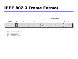
Frame check sequence (as in HDLC)
If frame OK and address matches receiver, send ACK
Frame may be damaged by noise or by another station
transmitting at the same time (collision)
Any overlap of frames causes collision
Max utilization 18%
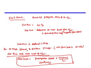
5.
Slotted ALOHA
Timein uniform slots equal to frame
transmission time
Need central clock (or other sync mechanism)
Transmission begins at slot boundary
Frames either miss or overlap totally
Max utilization 37%
6.
CSMA
Propagation timeis much less than transmission time
All stations know that a transmission has started
almost immediately
First listen for clear medium (carrier sense)
If medium idle, transmit
If two stations start at the same instant, collision
Wait reasonable time (round trip plus ACK contention)
No ACK then retransmit
Max utilization depends on propagation time (medium
length) and frame length
Longer frame and shorter propagation gives better utilization
Nonpersistent CSMA
1. Ifmedium is idle, transmit; otherwise, go to 2
2. If medium is busy, wait amount of time drawn from
probability distribution (retransmission delay) and
repeat 1
Random delays reduces probability of collisions
Consider two stations become ready to transmit at same time
While another transmission is in progress
If both stations delay same time before retrying, both will
attempt to transmit at same time
Capacity is wasted because medium will remain idle
following end of transmission
Even if one or more stations waiting
Nonpersistent stations deferential
9.
1-persistent CSMA
Toavoid idle channel time, 1-persistent protocol
used
Station wishing to transmit listens and obeys
following:
1. If medium idle, transmit; otherwise, go to step 2
2. If medium busy, listen until idle; then transmit
immediately
1-persistent stations selfish
If two or more stations waiting, collision guaranteed
Gets sorted out after collision
10.
P-persistent CSMA
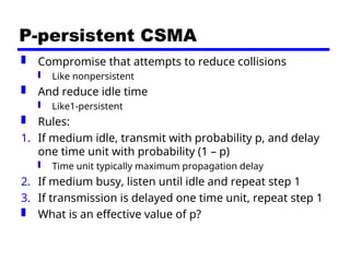
Compromisethat attempts to reduce collisions
Like nonpersistent
And reduce idle time
Like1-persistent
Rules:
1. If medium idle, transmit with probability p, and delay
one time unit with probability (1 – p)
Time unit typically maximum propagation delay
2. If medium busy, listen until idle and repeat step 1
3. If transmission is delayed one time unit, repeat step 1
What is an effective value of p?
11.
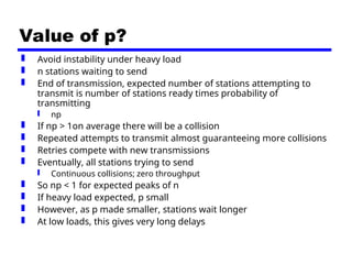
Value of p?
Avoid instability under heavy load
n stations waiting to send
End of transmission, expected number of stations attempting to
transmit is number of stations ready times probability of
transmitting
np
If np > 1on average there will be a collision
Repeated attempts to transmit almost guaranteeing more collisions
Retries compete with new transmissions
Eventually, all stations trying to send
Continuous collisions; zero throughput
So np < 1 for expected peaks of n
If heavy load expected, p small
However, as p made smaller, stations wait longer
At low loads, this gives very long delays
12.
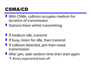
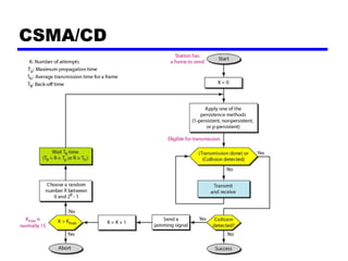
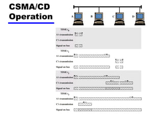
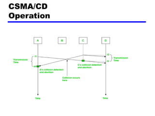
CSMA/CD
With CSMA,collision occupies medium for
duration of transmission
Stations listen whilst transmitting
If medium idle, transmit
If busy, listen for idle, then transmit
If collision detected, jam then cease
transmission
After jam, wait random time then start again
Binary exponential back off
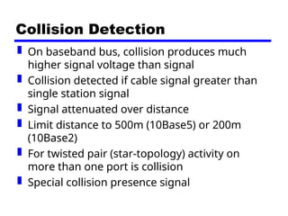
Collision Detection
Onbaseband bus, collision produces much
higher signal voltage than signal
Collision detected if cable signal greater than
single station signal
Signal attenuated over distance
Limit distance to 500m (10Base5) or 200m
(10Base2)
For twisted pair (star-topology) activity on
more than one port is collision
Special collision presence signal
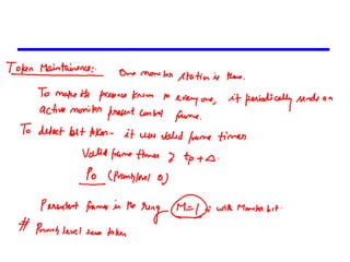
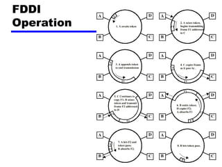
Token Ring (802.5)
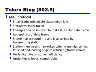
MAC protocol
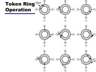
Small frame (token) circulates when idle
Station waits for token
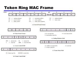
Changes one bit in token to make it SOF for data frame
Append rest of data frame
Frame makes round trip and is absorbed by
transmitting station
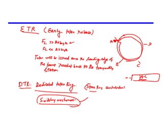
Station then inserts new token when transmission has
finished and leading edge of returning frame arrives
Under light loads, some inefficiency
Under heavy loads, round robin
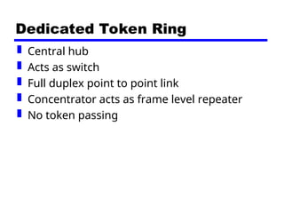
Dedicated Token Ring
Central hub
Acts as switch
Full duplex point to point link
Concentrator acts as frame level repeater
No token passing
25.
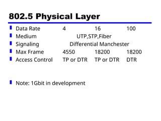
802.5 Physical Layer
Data Rate 4 16 100
Medium UTP,STP,Fiber
Signaling Differential Manchester
Max Frame 4550 18200 18200
Access Control TP or DTR TP or DTR DTR
Note: 1Gbit in development
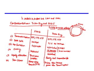
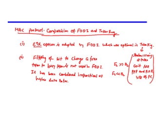
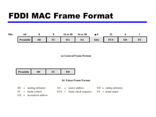
FDDI MAC Protocol
As for 802.5 except:
Station seizes token by aborting token
transmission
Once token captured, one or more data
frames transmitted
New token released as soon as transmission
finished (early token release in 802.5)
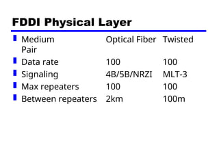
FDDI Physical Layer
Medium Optical Fiber Twisted
Pair
Data rate 100 100
Signaling 4B/5B/NRZI MLT-3
Max repeaters 100 100
Between repeaters 2km 100m
38.
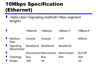
10Mbps Specification
(Ethernet)
<datarate><Signaling method><Max segment
length>
10Base5 10Base2 10Base-T 10Base-F
Medium Coaxial Coaxial UTP 850nm
fiber
Signaling Baseband Baseband Baseband
Manchester
ManchesterManchester Manchester On/Off
Topology Bus Bus Star Star
Nodes 100 30 - 33
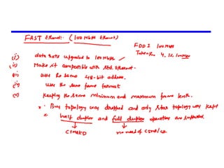
42.
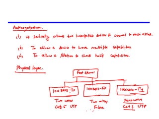
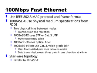
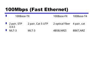
100Mbps Fast Ethernet
Use IEEE 802.3 MAC protocol and frame format
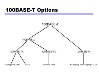
100BASE-X use physical medium specifications from
FDDI
Two physical links between nodes
Transmission and reception
100BASE-TX uses STP or Cat. 5 UTP
May require new cable
100BASE-FX uses optical fiber
100BASE-T4 can use Cat. 3, voice-grade UTP
Uses four twisted-pair lines between nodes
Data transmission uses three pairs in one direction at a time
Star-wire topology
Similar to 10BASE-T
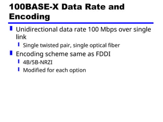
100BASE-X Data Rateand
Encoding
Unidirectional data rate 100 Mbps over single
link
Single twisted pair, single optical fiber
Encoding scheme same as FDDI
4B/5B-NRZI
Modified for each option
45.
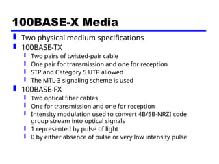
100BASE-X Media
Twophysical medium specifications
100BASE-TX
Two pairs of twisted-pair cable
One pair for transmission and one for reception
STP and Category 5 UTP allowed
The MTL-3 signaling scheme is used
100BASE-FX
Two optical fiber cables
One for transmission and one for reception
Intensity modulation used to convert 4B/5B-NRZI code
group stream into optical signals
1 represented by pulse of light
0 by either absence of pulse or very low intensity pulse
46.
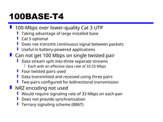
100BASE-T4
100-Mbps overlower-quality Cat 3 UTP
Taking advantage of large installed base
Cat 5 optional
Does not transmit continuous signal between packets
Useful in battery-powered applications
Can not get 100 Mbps on single twisted pair
Data stream split into three separate streams
Each with an effective data rate of 33.33 Mbps
Four twisted pairs used
Data transmitted and received using three pairs
Two pairs configured for bidirectional transmission
NRZ encoding not used
Would require signaling rate of 33 Mbps on each pair
Does not provide synchronization
Ternary signaling scheme (8B6T)
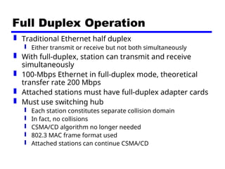
Full Duplex Operation
Traditional Ethernet half duplex
Either transmit or receive but not both simultaneously
With full-duplex, station can transmit and receive
simultaneously
100-Mbps Ethernet in full-duplex mode, theoretical
transfer rate 200 Mbps
Attached stations must have full-duplex adapter cards
Must use switching hub
Each station constitutes separate collision domain
In fact, no collisions
CSMA/CD algorithm no longer needed
802.3 MAC frame format used
Attached stations can continue CSMA/CD
49.
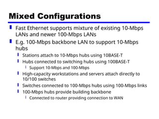
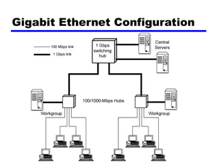
Mixed Configurations
FastEthernet supports mixture of existing 10-Mbps
LANs and newer 100-Mbps LANs
E.g. 100-Mbps backbone LAN to support 10-Mbps
hubs
Stations attach to 10-Mbps hubs using 10BASE-T
Hubs connected to switching hubs using 100BASE-T
Support 10-Mbps and 100-Mbps
High-capacity workstations and servers attach directly to
10/100 switches
Switches connected to 100-Mbps hubs using 100-Mbps links
100-Mbps hubs provide building backbone
Connected to router providing connection to WAN
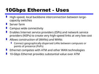
10Gbps Ethernet -Uses
High-speed, local backbone interconnection between large-
capacity switches
Server farm
Campus wide connectivity
Enables Internet service providers (ISPs) and network service
providers (NSPs) to create very high-speed links at very low cost
Allows construction of (MANs) and WANs
Connect geographically dispersed LANs between campuses or
points of presence (PoPs)
Ethernet competes with ATM and other WAN technologies
10-Gbps Ethernet provides substantial value over ATM
56.
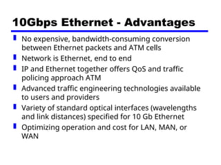
10Gbps Ethernet -Advantages
No expensive, bandwidth-consuming conversion
between Ethernet packets and ATM cells
Network is Ethernet, end to end
IP and Ethernet together offers QoS and traffic
policing approach ATM
Advanced traffic engineering technologies available
to users and providers
Variety of standard optical interfaces (wavelengths
and link distances) specified for 10 Gb Ethernet
Optimizing operation and cost for LAN, MAN, or
WAN
57.
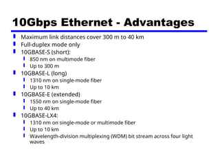
10Gbps Ethernet -Advantages
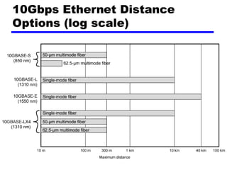
Maximum link distances cover 300 m to 40 km
Full-duplex mode only
10GBASE-S (short):
850 nm on multimode fiber
Up to 300 m
10GBASE-L (long)
1310 nm on single-mode fiber
Up to 10 km
10GBASE-E (extended)
1550 nm on single-mode fiber
Up to 40 km
10GBASE-LX4:
1310 nm on single-mode or multimode fiber
Up to 10 km
Wavelength-division multiplexing (WDM) bit stream across four light
waves