Longwall_top_coal_caving.pptx
•Download as PPTX, PDF•
0 likes•12 views

Método de Explotación de Carbón Longwall

Recommended
More Related Content
Similar to Longwall_top_coal_caving.pptx
Similar to Longwall_top_coal_caving.pptx (20)
Recently uploaded
Recently uploaded (20)
Longwall_top_coal_caving.pptx
- 1. A SEMINAR ON…. LONGWALL TOP COAL CAVING Presented by: J. Anil M.Tech-219MN1581 Department of Mining Engineering, NIT Rourkela, Odisha
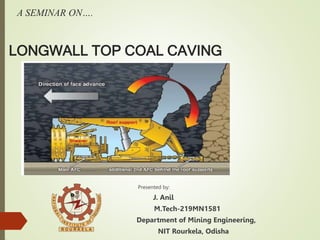
- 2. INTRODUCTION Long wall top coal caving (LTCC) is the method of extraction for underground mining of thick seam, i.e. greater than4.5m. It uses a long wall setup and natural forces to aid in the winning of coal. With this method of coal extraction only a single long wall is developed at foot of the seam accompanied by caving the reclamation of the top coal. The control of roof layer at the face by means of powered supports. At the face, the coal is mined with a shearer at a set height and transported out of face length by AFC and ACC to rate of advance, the upper coal section of seam is then induced to cave at the goaf side and is removed by a second AFC called “REAR COAL CONVEYOR” which is situated behind the face supports.
- 3. History of LTCC Longwall Top Coal Caving was initially developed in the former Soviet Union and France in the 1950s and 1960s. The ‘Soutirage’ method which was developed in France in the 1960s is considered as the original form of LTCC. It was then applied in the former Yugoslavia, Hungary, Romania, the former Czechoslovakia and Turkey. After the mid-1980s, LTCC was abandoned in Europe because the levels of productivity from LTCC faces were less than that from conventional longwalls during that time. Since the late 1980s, LTCC has been introduced, developed and improved in China. The method is widely applied to extract thick seams in China with a significant innovation on equipment.
- 4. BENEFITS OF LTCCC This method provides greater resource recovery, as it offers a variable means of extraction up to 75-80% in the 5-9m thickness range. Mine safety is improved as the cutting height is lower relative to the high reach single pass longwall method. Reduced operating costs are possible as LTCC method increases the longwall tonnage per meter retract and also per meter of gate road development. Compared to other longwall mining methods (High reach single pass longwall, Multislice longwall) LTCC results in improved face control , smaller and less expensive equipment and improved spontaneous combustion control .
- 5. DRAWBACKS OF LTCC Roof and face alignment. Roof support control. Spontaneous combustion control. Managing airborne dust. Strata control. Dust and significant face disruption due to top coal drawing.
- 6. OPERATION OF LTCC • This method employs both cutting of the lower portion of the coal seam accompanied by caving and reclamation of top coal. • Coal is first cut from the long wall face using a conventional shearer and AFC arrangement working under a hydraulic face supports that incorporates a rear coal conveyor and a cantilevers or flipper arrangement located on the lower portion of rear canopy. • Face cutting heights are generally in range of 2.8-3.0m. • The roof support is advanced forward after the shearer and the rear conveyor remains in place in preparation for caving sequence. • This caving sequence allows the broken coal at the rear of supports to flow from the goaf on to the rear conveyor, which conveys it to the gate end transfer.
- 8. MECHANISM OF LTCC A secondary caving process may be repeated if further coal is present before the rear conveyor and is finally advanced forward under rear canopy of support ready for the next shearer cycle. Once an area has been caved the rear cantilever is extended blackout into the goaf stopping any further influx of goaf material. The flow of coal on to the rear conveyor is controlled by the retracting the rear cantilevers of selected supports exposing the rear conveyor to the goaf coal which caves on to the face space. Top coal fracturing occurs through shear failure and tensile cracking.
- 9. CHALLENGES TO INTRODUCING LTCC Geological and Geotechnical matters. Mining Environment. Equipment design and performance.
- 10. GEOLOGICAL AND GEO TECHNICAL MATTERS scientific & engineering studies and detail investigations are required to determine a particular site’s potential for LTCC. The fracturing process begins ahead of face line when seam acted on by abutment stress. The process of fracturing and crack evolution in top coal is critical to the success of LTCC and is depend on abutment pressure and coal mass strength. Top coal fracturing occurs through shear failure and tensile cracking. Poor fracturing will cause large blocks to form and this results in poor caving through rear AFC. Excessive fracturing will in turn causes roof control problems ahead of roof supports.
- 11. CAVING ASSESMENT • This will depends on following parameters. 1. Coal strength. 2. Vertical stress. 3. Thickness of top coal. 4. Degree of fracturing. 5. Interburden/stone band thickness. • Modelling of LTCC complicated as the strata must be modelled and assessed through the various loading stages that will result in increasing fracturing of top coal, from being intact to the fully fractured and expanded. • This requirement necessitates using two different approaches known as CONTINUUM & DISCRETE ELEMENT MODELLING to represent two coal conditions
- 12. MINING ENVIRONMENT Use of the LTCC method causes changes to mining environment particularly in air flow pattern, gas emissions and airborne dust generation . LTCC uses four leg shield supports with rear AFC which significantly alters ventilation behaviour on around the face. Additional airborne dust will be present on LTCC faces due to addition of caving cycle that produces a large quantities of dust. Gas make into and out of LTCC goaves may be significantly different compared to the conventional longwall goafs in the same conditions ,it is due to larger extraction volume and its effect on the surrounding strata and coal seam
- 13. EQUIPMENT DESIGN AND PERFORMANCE An equipment manufacturer and mine operator must consider the design life of equipment for LTCC applications. A short design life will allow for new equipment design while long design life will be more expensive to purchase. The path chosen will depends largely on the mine operators confidence in assessment of caving conditions. As with the all longwall faces the general guidelines for an efficient face are maintaining correct face alignment and horizon control. Automation of caving process will involve programming the time of the retraction and extension of rear cantilever.
- 14. PARAMETERS INFLUENCING TOP COAL CAVABILITY Coal seam characteristics. Surrounding rock strata. Stress conditions.
- 15. COAL SEAM CHARACTERISTICS Coal seam characteristics include 1. Coal strength. 2. Cutting height. 3. Coal discontinuities. • The coal strength which indicates resistance to failure. The Uniaxial Compressive Strength (UCS) is generally used to represent the rock strength. • The cutting height and top coal thickness are considered to affect the quantity and quality of coal cavity. • The ratio of top coal thickness to the cutting height should be reasonably set to obtain successful caving and this value generally varies from 1 to 3. • Discontinuities is commonly employed as collective term for all fractures in a rock mass that have zero to low tensile strength.
- 16. SURROUDING ROCK STRATA CHARACTERISTICS The immediate roof must be certain thickness and caves immediately or with little delay after advance of support. If an immediate roof is weak and thin it will converge to top coal due to the load from upper strata and its own weight, this causes an increase of stress on top coal that will facilitates the coal failure. Therefore top coal will easier to cave. If an immediate roof is strong and thick it resists the force from the upper strata and its own weight on top coal. As a result top coal will be more difficult to cave. The main roof affects the stability of immediate roof and influences the top coal behaviour. A weak floor rock may result in support instability or floor heaving. These issue disturb caving sequence.
- 17. STRESS CONDITIONS • The underground mining cause stress redistribution and forms a new equilibrium stress directly affect material failure and therefore influence the top coal cavability. • For LTCC mining the vertical stress component is redistributed and results in different stress zones. • The formation of high vertical abutment stress zones induces the top coal to fail and to cave under the impact of gravity. • The horizontal stress component, however has an ambiguous effect on caving. • On the other hand, it can constrain the load transference from upper to lower strata. This reduces the level of coal failure and finally decreases cavability.
- 19. OTHER PARAMETERS Panel design. Seam dip. Ground water. • A face orientation at an angle of 45 degree to the face vertical joint might cause a better top coal recovery in centre of panel width compared with non oriented panel.
- 20. CAVABILITY ASSEESSMENT METHODS AND CLASSIFICATIONS Chinese Approach: 1. Fracture index method. 2. Fuzzy cluster evaluation method. 3. Statical analysis method.
- 21. NUMERICAL MODELING APPROACH The numerical modelling provides a predictive and effective tool to access the top coal caving. 1.CONTINUUM METHODS Finite difference method (FDM). Finite element method (FEM). Boundary element method (BEM). 2.DISCONTINUUM METHODS Distinct element method (DEM). 3.HYBRID METHODS A hybrid FLAC method was developed to acess the top coal caving.
- 22. THANK YOU..
Editor's Notes
- . 0