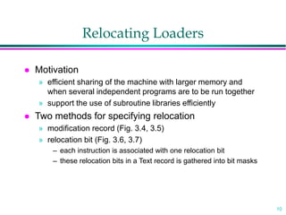
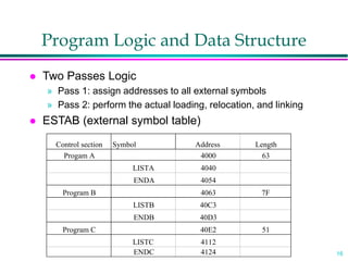
1
Loaders and Linkers
Chapter 3
System Software
An introduction to systems programming
Leland L. Beck
2
Introduction
 To execute an object program, we needs
» Relocation, which modifies the object program so that it can be
loaded at an address different from the location originally specified
» Linking, which combines two or more separate object programs
and supplies the information needed to allow references between
them
» Loading and Allocation, which allocates memory location and
brings the object program into memory for execution
3
Overview of Chapter 3
 Type of loaders
» assemble-and-go loader
» absolute loader (bootstrap loader)
» relocating loader (relative loader)
» direct linking loader
 Design options
» linkage editors
» dynamic linking
» bootstrap loaders
4
Assemble-and-go Loader
 Characteristic
» the object code is stored in memory after assembly
» single JUMP instruction
 Advantage
» simple, developing environment
 Disadvantage
» whenever the assembly program is to be executed, it has to
be assembled again
» programs have to be coded in the same language
5
Design of an Absolute Loader
 Absolute Program
» Advantage
– Simple and efficient
» Disadvantage
– the need for programmer to specify the actual address
– difficult to use subroutine libraries
 Program Logic
6
Fig. 3.2 Algorithm for an absolute loader
Begin
read Header record
verify program name and length
read first Text record
while record type is not ‘E’ do
begin
{if object code is in character form, convert into internal
representation}
move object code to specified location in memory
read next object program record
end
jump to address specified in End record
end
7
Object Code Representation
 Figure 3.1 (a)
» each byte of assembled code is given using its hexadecimal
representation in character form
» easy to read by human beings
 In general
» each byte of object code is stored as a single byte
» most machine store object programs in a binary form
» we must be sure that our file and device conventions do not
cause some of the program bytes to be interpreted as
control characters
8
A Simple Bootstrap Loader
 Bootstrap Loader
» When a computer is first tuned on or restarted, a special
type of absolute loader, called bootstrap loader is executed
» This bootstrap loads the first program to be run by the
computer -- usually an operating system
 Example (SIC bootstrap loader)
» The bootstrap itself begins at address 0
» It loads the OS starting address 0x80
» No header record or control information, the object code is
consecutive bytes of memory
9
Fig. 3.3 SIC Bootstrap Loader Logic
Begin
X=0x80 (the address of the next memory location to be loaded
Loop
AGETC (and convert it from the ASCII character code to the value
of the hexadecimal digit)
save the value in the high-order 4 bits of S
AGETC
combine the value to form one byte A (A+S)
store the value (in A) to the address in register X
XX+1
End
0~9 : 48
A~F : 65
GETC Aread one character
if A=0x04 then jump to 0x80
if A<48 then GETC
A  A-48 (0x30)
if A<10 then return
A  A-7 (48+7=55)
return
10
Relocating Loaders
 Motivation
» efficient sharing of the machine with larger memory and
when several independent programs are to be run together
» support the use of subroutine libraries efficiently
 Two methods for specifying relocation
» modification record (Fig. 3.4, 3.5)
» relocation bit (Fig. 3.6, 3.7)
– each instruction is associated with one relocation bit
– these relocation bits in a Text record is gathered into bit masks
11
Modification Record
 For complex machines
 Also called RLD specification
» Relocation and Linkage Directory
Modification record
col 1: M
col 2-7: relocation address
col 8-9: length (halfbyte)
col 10: flag (+/-)
col 11-17: segment name
12
Relocation Bit
 For simple machines
 Relocation bit
» 0: no modification is necessary
» 1: modification is needed
 Twelve-bit mask is used in each Text record
» since each text record contains less than 12 words
» unused words are set to 0
» any value that is to be modified during relocation must
coincide with one of these 3-byte segments
– e.g. line 210
Text record
col 1: T
col 2-7: starting address
col 8-9: length (byte)
col 10-12: relocation bits
col 13-72: object code
13
Program Linking
 Goal
» Resolve the problems with EXTREF and EXTDEF from different
control sections
 Linking
» 1. User, 2. Assembler, 3. Linking loader
 Example
» Program in Fig. 3.8 and object code in Fig. 3.9
» Use modification records for both relocation and linking
– address constant
– external reference
14
Program Linking Example
Program A Program B Program C
Label Expression LISTA, ENDA LISTB, ENDB LISTC, ENDC
REF1 LISTA local, R, PC external external
REF2 LISTB+4 external local, R, PC external
REF3 ENDA-LISTA local, A external external
REF4 ENDA-LISTA+LISTC local, A external local, R
REF5 ENDC-LISTC-10 external external local, A
REF6 ENDC-LISTC+LISTA-1 local, R external local, A
REF7 ENDA-LISTA-(ENDB-LISTB) local, A local, A external
REF8 LISTB-LISTA local, R local, R external
15
Program Linking Example
 Fig. 3.10
 Load address for control sections
» PROGA 004000 63
» PROGB 004063 7F
» PROGC 0040E2 51
 Load address for symbols
» LISTA: PROGA+0040=4040
» LISTB: PROGB+0060=40C3
» LISTC: PROGC+0030=4112
 REF4 in PROGA
» ENDA-LISTA+LISTC=14+4112=4126
» T0000540F000014FFFFF600003F000014FFFFC0
» M00005406+LISTC
16
Program Logic and Data Structure
 Two Passes Logic
» Pass 1: assign addresses to all external symbols
» Pass 2: perform the actual loading, relocation, and linking
 ESTAB (external symbol table)
Control section Symbol Address Length
Progam A 4000 63
LISTA 4040
ENDA 4054
Program B 4063 7F
LISTB 40C3
ENDB 40D3
Program C 40E2 51
LISTC 4112
ENDC 4124
17
Pass 1 Program Logic
 Pass 1:
» assign addresses to all external symbols
 Variables
» PROGADDR (program load address) from OS
» CSADDR (control section address)
» CSLTH (control section length)
» ESTAB
 Fig. 3.11(a)
» Process Define Record
18
Pass 2 Program Logic
 Pass 1:
» perform the actual loading, relocation, and linking
 Modification record
» lookup the symbol in ESTAB
 End record for a main program
» transfer address
 Fig. 3.11(b)
» Process Text record and Modification record
19
Improve Efficiency
 Use local searching instead of multiple searches of
ESTAB for the same symbol
» assign a reference number to each external symbol
» the reference number is used in Modification records
 Implementation
» 01: control section name
» other: external reference symbols
 Example
» Fig. 3.12
20
Figure 3.12
Ref No. Symbol Address
1 PROGA 4000
2 LISTB 40C3
3 ENDB 40D3
4 LISTC 4112
5 ENDC 4124
Ref No. Symbol Address
1 PROGB 4063
2 LISTA 4040
3 ENDA 4054
4 LISTC 4112
5 ENDC 4124
Ref No. Symbol Address
1 PROGC 4063
2 LISTA 4040
3 ENDA 4054
4 LISTB 40C3
5 ENDB 40D3
PROGA
PROGB PROGC

loader.ppt

  • 1.
    1 Loaders and Linkers Chapter3 System Software An introduction to systems programming Leland L. Beck
  • 2.
    2 Introduction  To executean object program, we needs » Relocation, which modifies the object program so that it can be loaded at an address different from the location originally specified » Linking, which combines two or more separate object programs and supplies the information needed to allow references between them » Loading and Allocation, which allocates memory location and brings the object program into memory for execution
  • 3.
    3 Overview of Chapter3  Type of loaders » assemble-and-go loader » absolute loader (bootstrap loader) » relocating loader (relative loader) » direct linking loader  Design options » linkage editors » dynamic linking » bootstrap loaders
  • 4.
    4 Assemble-and-go Loader  Characteristic »the object code is stored in memory after assembly » single JUMP instruction  Advantage » simple, developing environment  Disadvantage » whenever the assembly program is to be executed, it has to be assembled again » programs have to be coded in the same language
  • 5.
    5 Design of anAbsolute Loader  Absolute Program » Advantage – Simple and efficient » Disadvantage – the need for programmer to specify the actual address – difficult to use subroutine libraries  Program Logic
  • 6.
    6 Fig. 3.2 Algorithmfor an absolute loader Begin read Header record verify program name and length read first Text record while record type is not ‘E’ do begin {if object code is in character form, convert into internal representation} move object code to specified location in memory read next object program record end jump to address specified in End record end
  • 7.
    7 Object Code Representation Figure 3.1 (a) » each byte of assembled code is given using its hexadecimal representation in character form » easy to read by human beings  In general » each byte of object code is stored as a single byte » most machine store object programs in a binary form » we must be sure that our file and device conventions do not cause some of the program bytes to be interpreted as control characters
  • 8.
    8 A Simple BootstrapLoader  Bootstrap Loader » When a computer is first tuned on or restarted, a special type of absolute loader, called bootstrap loader is executed » This bootstrap loads the first program to be run by the computer -- usually an operating system  Example (SIC bootstrap loader) » The bootstrap itself begins at address 0 » It loads the OS starting address 0x80 » No header record or control information, the object code is consecutive bytes of memory
  • 9.
    9 Fig. 3.3 SICBootstrap Loader Logic Begin X=0x80 (the address of the next memory location to be loaded Loop AGETC (and convert it from the ASCII character code to the value of the hexadecimal digit) save the value in the high-order 4 bits of S AGETC combine the value to form one byte A (A+S) store the value (in A) to the address in register X XX+1 End 0~9 : 48 A~F : 65 GETC Aread one character if A=0x04 then jump to 0x80 if A<48 then GETC A  A-48 (0x30) if A<10 then return A  A-7 (48+7=55) return
  • 10.
    10 Relocating Loaders  Motivation »efficient sharing of the machine with larger memory and when several independent programs are to be run together » support the use of subroutine libraries efficiently  Two methods for specifying relocation » modification record (Fig. 3.4, 3.5) » relocation bit (Fig. 3.6, 3.7) – each instruction is associated with one relocation bit – these relocation bits in a Text record is gathered into bit masks
  • 11.
    11 Modification Record  Forcomplex machines  Also called RLD specification » Relocation and Linkage Directory Modification record col 1: M col 2-7: relocation address col 8-9: length (halfbyte) col 10: flag (+/-) col 11-17: segment name
  • 12.
    12 Relocation Bit  Forsimple machines  Relocation bit » 0: no modification is necessary » 1: modification is needed  Twelve-bit mask is used in each Text record » since each text record contains less than 12 words » unused words are set to 0 » any value that is to be modified during relocation must coincide with one of these 3-byte segments – e.g. line 210 Text record col 1: T col 2-7: starting address col 8-9: length (byte) col 10-12: relocation bits col 13-72: object code
  • 13.
    13 Program Linking  Goal »Resolve the problems with EXTREF and EXTDEF from different control sections  Linking » 1. User, 2. Assembler, 3. Linking loader  Example » Program in Fig. 3.8 and object code in Fig. 3.9 » Use modification records for both relocation and linking – address constant – external reference
  • 14.
    14 Program Linking Example ProgramA Program B Program C Label Expression LISTA, ENDA LISTB, ENDB LISTC, ENDC REF1 LISTA local, R, PC external external REF2 LISTB+4 external local, R, PC external REF3 ENDA-LISTA local, A external external REF4 ENDA-LISTA+LISTC local, A external local, R REF5 ENDC-LISTC-10 external external local, A REF6 ENDC-LISTC+LISTA-1 local, R external local, A REF7 ENDA-LISTA-(ENDB-LISTB) local, A local, A external REF8 LISTB-LISTA local, R local, R external
  • 15.
    15 Program Linking Example Fig. 3.10  Load address for control sections » PROGA 004000 63 » PROGB 004063 7F » PROGC 0040E2 51  Load address for symbols » LISTA: PROGA+0040=4040 » LISTB: PROGB+0060=40C3 » LISTC: PROGC+0030=4112  REF4 in PROGA » ENDA-LISTA+LISTC=14+4112=4126 » T0000540F000014FFFFF600003F000014FFFFC0 » M00005406+LISTC
  • 16.
    16 Program Logic andData Structure  Two Passes Logic » Pass 1: assign addresses to all external symbols » Pass 2: perform the actual loading, relocation, and linking  ESTAB (external symbol table) Control section Symbol Address Length Progam A 4000 63 LISTA 4040 ENDA 4054 Program B 4063 7F LISTB 40C3 ENDB 40D3 Program C 40E2 51 LISTC 4112 ENDC 4124
  • 17.
    17 Pass 1 ProgramLogic  Pass 1: » assign addresses to all external symbols  Variables » PROGADDR (program load address) from OS » CSADDR (control section address) » CSLTH (control section length) » ESTAB  Fig. 3.11(a) » Process Define Record
  • 18.
    18 Pass 2 ProgramLogic  Pass 1: » perform the actual loading, relocation, and linking  Modification record » lookup the symbol in ESTAB  End record for a main program » transfer address  Fig. 3.11(b) » Process Text record and Modification record
  • 19.
    19 Improve Efficiency  Uselocal searching instead of multiple searches of ESTAB for the same symbol » assign a reference number to each external symbol » the reference number is used in Modification records  Implementation » 01: control section name » other: external reference symbols  Example » Fig. 3.12
  • 20.
    20 Figure 3.12 Ref No.Symbol Address 1 PROGA 4000 2 LISTB 40C3 3 ENDB 40D3 4 LISTC 4112 5 ENDC 4124 Ref No. Symbol Address 1 PROGB 4063 2 LISTA 4040 3 ENDA 4054 4 LISTC 4112 5 ENDC 4124 Ref No. Symbol Address 1 PROGC 4063 2 LISTA 4040 3 ENDA 4054 4 LISTB 40C3 5 ENDB 40D3 PROGA PROGB PROGC