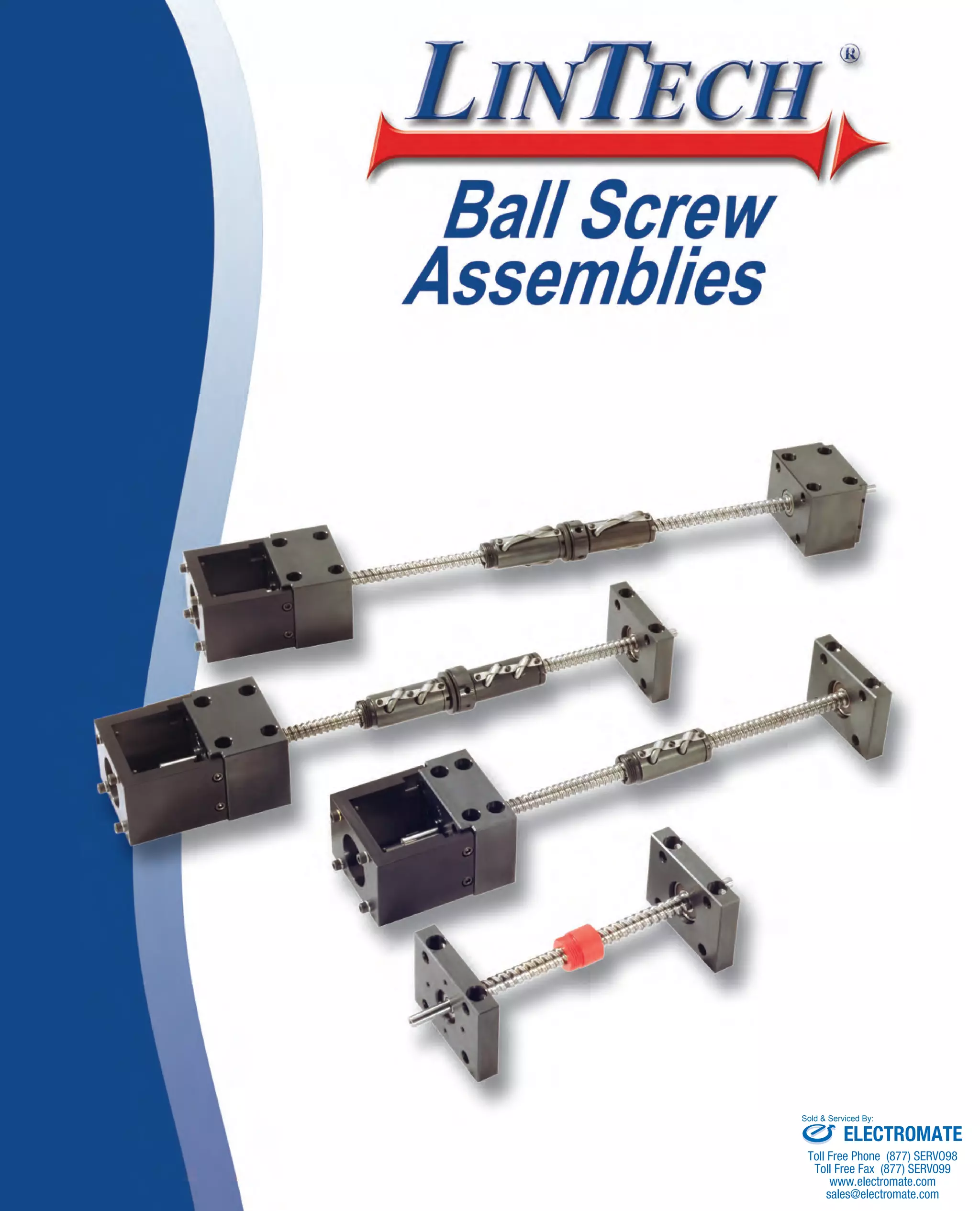
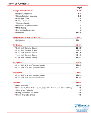
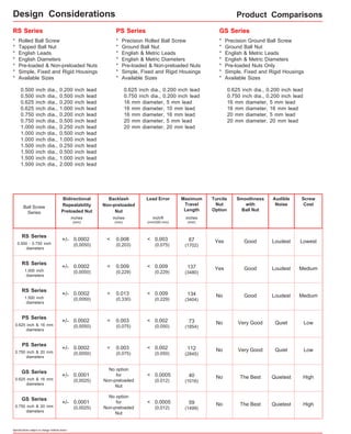
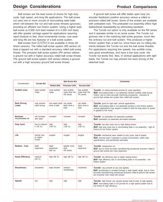
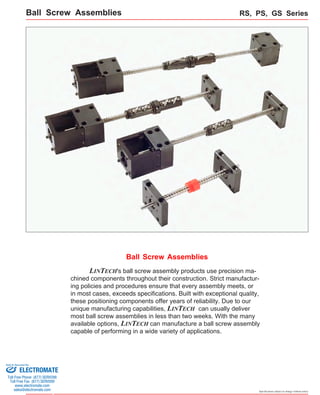
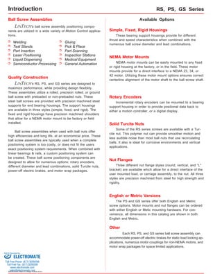
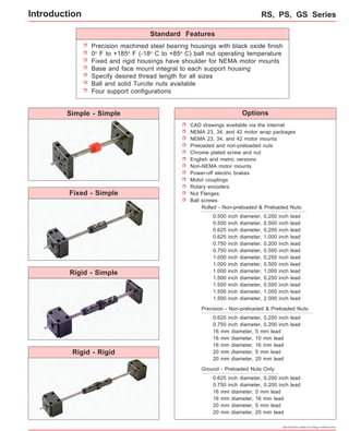
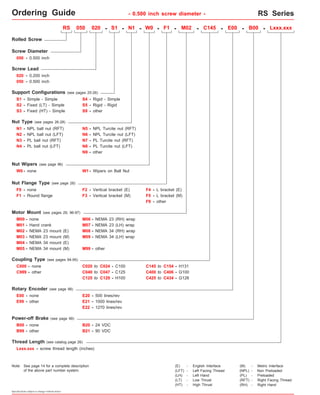
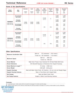
Sold & Serviced By: 
ELECTROMATE 
Toll Free Phone (877) SERVO98 
Toll Free Fax (877) SERV099 
www.electromate.com 
sales@electromate.com
Pages 
2 - 18 
Design Considerations 
Product Comparisons 2 - 4 
Application Guide 9 
Screw Travel Life 
Maximum Speed 
Maximum Compression Load 
Motor Sizing 13 
Iintroduction of RS, PS and GS 19 - 21 
0.500 inch Diameter Screws 
0.625 inch Diameter Screws 
0.750 inch Diameter Screws 
1.000 inch Diameter Screws 
PS Series 62 - 77 
GS Series 78 - 93 
Motor Couplings 
Hand Crank, Other Motor Mounts, Wiper Kits, Bellows, and Chrome Plating 
Motor Wrap Packages 
Rotary Incremental Encoders 
Power-off Electric Brakes 
5 - 8 
10 
11 
How to Select an Assembly 
12 
Introduction 19 - 21 
RS Series 22 - 61 
22 - 29 
30 - 37 
38 - 45 
46 - 53 
Options 94 - 99 
94 - 95 
96 
97 
98 
99 
Part Number Description 
Definitions 
14 
15 - 18 
1.500 inch Diameter Screws 54 - 61 
0.625 inch & 16 mm Diameter Screws 
0.750 inch & 20 mm Diameter Screws 
62 - 69 
70 - 77 
0.625 inch & 16 mm Diameter Screws 
0.750 inch & 20 mm Diameter Screws 
78 - 85 
86 - 93 
Table of Contents 
Sold & Serviced By: 
ELECTROMATE 
Toll Free Phone (877) SERVO98 
Toll Free Fax (877) SERV099 
www.electromate.com 
sales@electromate.com
Design Considerations Product Comparisons 
+/- 0.0002 Yes 
+/- 0.0002 No 
+/- 0.0002 No 
+/- 0.0002 No 
Specifications subject to change without notice 
Lead Error 
< 0.008 
(0,203) 
Yes 
Backlash 
Non-preloaded 
Nut 
Bidirectional 
Repeatability 
Preloaded Nut 
inch/ft 
(mm/300 mm) 
+/- 0.0002 
(0,0050) 
RS Series 
0.500 - 0.750 inch 
diameters 
Good 
inches 
(mm) 
inches 
(mm) 
< 0.003 
(0,075) 
Loudest Lowest 
RS Series PS Series GS Series 
* Rolled Ball Screw 
* Precision Rolled Ball Screw 
* Tapped Ball Nut 
* Ground Ball Nut 
* English Leads 
* English & Metric Leads 
* English Diameters 
* English & Metric Diameters 
* Pre-loaded & Non-preloaded Nuts 
* Simple, Fixed and Rigid Housings 
* Available Sizes 
* Available Sizes 
* Precision Ground Ball Screw 
* Ground Ball Nut 
* English & Metric Leads 
* English & Metric Diameters 
* Pre-loaded Nuts Only 
* Simple, Fixed and Rigid Housings 
* Available Sizes 
inches 
(mm) 
67 
(1702) 
< 0.009 
(0,229) 
(0,0050) 
RS Series 
1.000 inch 
diameters 
< 0.009 Good 
(0,229) 
137 Loudest Medium 
(3480) 
< 0.013 
(0,330) 
(0,0050) 
RS Series 
1.500 inch 
diameters 
< 0.009 Good 
(0,229) 
134 Loudest Medium 
(3404) 
< 0.003 
(0,075) 
(0,0050) 
PS Series 
0.625 inch & 16 mm 
diameters 
< 0.002 Very Good 
(0,050) 
73 Quiet Low 
(1854) 
+/- 0.0001 No 
(0,0025) 
GS Series 
0.625 inch & 16 mm 
diameters 
< 0.0005 The Best 
(0,012) 
40 Quietest High 
(1016) 
Ball Screw 
Series 
No option 
for 
Non-preloaded 
Nut 
0.500 inch dia., 0.200 inch lead 
0.500 inch dia., 0.500 inch lead 
0.625 inch dia., 0.200 inch lead 
0.625 inch dia., 1.000 inch lead 
0.750 inch dia., 0.200 inch lead 
0.750 inch dia., 0.500 inch lead 
1.000 inch dia., 0.250 inch lead 
1.000 inch dia., 0.500 inch lead 
1.000 inch dia., 1.000 inch lead 
1.500 inch dia., 0.250 inch lead 
1.500 inch dia., 0.500 inch lead 
1.500 inch dia., 1.000 inch lead 
1.500 inch dia., 2.000 inch lead 
0.625 inch dia., 0.200 inch lead 
0.750 inch dia., 0.200 inch lead 
16 mm diameter, 5 mm lead 
16 mm diameter, 10 mm lead 
16 mm diameter, 16 mm lead 
20 mm diameter, 5 mm lead 
20 mm diameter, 20 mm lead 
0.625 inch dia., 0.200 inch lead 
0.750 inch dia., 0.200 inch lead 
16 mm diameter, 5 mm lead 
16 mm diameter, 16 mm lead 
20 mm diameter, 5 mm lead 
20 mm diameter, 20 mm lead 
< 0.003 
(0,075) 
(0,0050) 
PS Series 
0.750 inch & 20 mm 
diameters 
< 0.002 Very Good 
(0,050) 
112 Quiet Low 
(2845) 
+/- 0.0001 No 
(0,0025) 
GS Series 
0.750 inch & 20 mm 
diameters 
< 0.0005 The Best 
(0,012) 
59 Quietest High 
(1499) 
No option 
for 
Non-preloaded 
Nut 
Screw 
Cost 
Audible 
Noise 
Smoothness 
with 
Ball Nut 
Turcite 
Nut 
Option 
Maximum 
Travel 
Length 
Design Consideration
Audible noise Turcite: no rolling elements provide for quiet operation. 
Duty Cycle Turcite: low duty cycle due to high sliding friction. 
high 
(100 %) 
longest 
Relative - Cost Turcite: inexpensive nut. 
slightly more 
than 
RS series 
Screw Efficiency Turcite: low efficiency due to higher sliding friction. 
Specifications subject to change without notice 
Ball screws are the lead screw of choice for high duty 
cycle, high speed, and long life applications. The ball screw 
nut uses one or more circuits of recirculating steel balls 
which roll between the nut and ball screw threads (grooves), 
providing an efficient low friction system. Using a higher lead 
ball screw (a 0.500 inch lead instead of a 0.200 inch lead) 
will offer greater carriage speed for applications requiring 
rapid traverse or fast, short incremental moves. Low wear 
and long life are key features of a ball screw system. 
Ball screws from LINTECH are available in three dif-ferent 
versions. The rolled ball screw system (RS series) uti-lizes 
a tapped nut with a standard accuracy rolled ball screw 
thread. The precision ball screw system (PS series) utilizes 
a ground nut with a higher accuracy rolled ball screw thread. 
The ground ball screw system (GS series) utilizes a ground 
nut with a high accuracy ground ball screw thread. 
A ground ball screw will offer better open loop (no 
encoder feedback) position accuracy versus a rolled or 
precision rolled ball screw. Some of the screws are available 
with preloaded nuts. The preloaded nut assembly offers high 
bidirectional repeatability by eliminating backlash. 
The Turcite nut option is only available on the RS series 
and it operates similar to an acme screw. The Turcite nut 
grooves ride in the matching ball screw grooves, much like 
the ordinary nut and bolt system. This produces a higher 
friction system than a ball nut, since there are no rolling ele-ments 
between the Turcite nut and the ball screw threads. 
For applications requiring low speeds, low audible noise, 
very good smoothness, and have a low duty cycle, the 
Turcite nut works fine. Also, in vertical applications with light 
loads, the Turcite nut may prevent the back driving of the 
attached load. 
Consideration 
Comments 
Turcite Nut 
Ball Screw Nut 
Rolled (RS) Ground (GS) 
less audible 
noise than the 
PS series 
most audible 
noise 
least audible 
noise 
Ball: recirculating balls in nut assembly transmit audible noise during 
motion; due to more accurate machining procedures - precision & 
ground ball screws are quieter than rolled ball screws. 
can easily 
back drive a 
load 
can easily back 
drive a load 
may prevent 
back driving 
Back Driving 
Loads 
Turcite: good for light load, vertical applications. 
Ball: recirculating balls in nut assembly produce a low friction system; 
vertical applications may require a brake to hold the load when no power 
is applied to the motor. 
will increase constant constant 
with wear 
Backlash 
non-preloaded nut 
Turcite: no preloaded nut assembly available. 
Ball: preloaded nut assembly eliminates backlash. 
medium high (90 %) high (90 %) 
(60 %) 
Ball: high efficiency due to recirculating balls in nut assembly - low 
friction system. 
Smoothness smoothest least smooth smoothest Turcite: very smooth at very low speeds. 
Ball: smoothness is constant through a wide speed range; due to more 
accurate manufacturing procedures precision rolled & ground ball screws 
are smoother than rolled ball screws. 
Speeds low high high Turcite: high friction can causes excess heat & wear at high speeds. 
Ball: recirculating balls in nut provide for a high speed system due to 
low friction & high efficiency. 
high 
(100 %) 
high 
(100 %) 
low to medium 
(< 50 %) 
Ball: high duty cycle due to recirculating balls in nut assembly - high ef-ficiency 
& low friction system. 
Life Turcite: mechanical wear related to duty cycle, load & speed. 
Ball: minimal wear if operated in proper environment, within load 
specifications, and periodically lubricated. 
shorter due 
to higher 
friction 
longest longest 
most 
expensive 
least 
expensive 
ball nut 
least 
expensive 
Ball: due to more accurate manufacturing procedures precision rolled & 
ground ball screws are more expensive. 
Precision (PS) 
less audible 
noise than the 
RS series 
can easily 
back drive a 
load 
constant 
high (90 %) 
medium 
smoothness 
high 
Product Comparisons 
Design Considerations
Simple Support Housing 
* All Steel Construction 
* Black Oxide Finish 
* 1 Sealed Radial Bearing 
* No Lubrication Required 
* Base or Face Mounted 
Fixed (HT) Support Housing 
* All Steel Construction 
* Black Oxide Finish 
* 2 Back to Back Angular Contact Bearings 
* No Lubrication Required 
* Lip Seals 
* Base or Face Mounted 
* Motor Mount Options 
Specifications subject to change without notice 
Product Comparisons 
Fixed (LT) Support Housing 
* All Steel Construction 
* Black Oxide Finish 
* 2 Back to Back Sealed Radial Bearings 
* No Lubrication Required 
* Lip Seals 
* Base or Face Mounted 
* Motor Mount Options 
Rigid Support Housing 
* All Steel Construction 
* Black Oxide Finish 
* 2 Separated Angular Contact Bearings 
* No Lubrication Required 
* Lip Seals 
* Base or Face Mounted 
* Motor Mount Options 
Some 
Compression Load 
versus 
Screw Length 
Maximum 
Speed 
(rpm) 
Simple-Simple Low Low 
Low Lowest Lowest 
Fixed(LT)-Simple 
Fixed(HT)-Simple 
Rigid-Simple 
Rigid-Rigid 
Low Medium Low Low None Low 
Low High Low Medium None Medium 
Medium High Medium Medium None High 
High High High Highest None Highest 
Possible 
Configurations 
Screw 
End Play 
(Backlash) 
Thrust 
Load 
Breakaway 
Torque 
Support 
Housing 
Cost 
Design Considerations 
Sold & Serviced By: 
ELECTROMATE 
Toll Free Phone (877) SERVO98 
Toll Free Fax (877) SERV099 
www.electromate.com 
sales@electromate.com
How to Select an Assembly 
= Weight Operating Load 
(as seen by lead screw) 
Sold & Serviced By: 
Specifications subject to change without notice 
Overview 
LINTECH's ball screw assemblies can be used in a wide 
variety of Motion Control applications. Proper selection of 
an assembly will yield a system that meets the performance 
requirements with trouble free long term operation. The fol-lowing 
steps should be used as a guide to aid in the selection 
process. 
Step 1 - 
Step 2 - 
Step 3 - 
Step 4 - 
Step 5 - 
Step 6 - 
Step 7 - 
Step 8 - 
Initial system requirements 
Determine the desired travel life 
Determine the effect of the load 
Determine the maximum safe speed 
Determine the safe compression load 
Check the Support Configuration 
Applying safety factors 
Review other issues 
Step 3 - Determine the Effect of the Load 
Will the ball screw assembly be mounted in a horizontal 
or vertical plane? We need to determine the load as seen by 
the "ball screw nut" and as seen by the "support housings". 
In a horizontal application, the screw and support housing 
only see the load times the coefficient of friction for the linear 
bearing structure. Coefficient of friction for various linear 
bearing surfaces differ, however for recirculating ball bearing 
style a 0.01 value can be used. In a vertical application, the 
ball screw nut and the support housing see the entire load 
as an axial force. Whenever possible, it is best to set-up the 
ball screw assembly in "Tension Loading" versus "Compres-sion 
Loading" for vertical applications. This can be done by 
mounting the "Fixed" or "Rigid" motor mount housing above 
the screw. 
Step 1 - Initial System Requirements 
Several important items should be identified initially. They 
are: plane of operation, total load weight, system maximum 
speed, desired travel length, and system repeatability. An-swers 
to these items are required as we move onto the next 
steps. 
Step 2 - Determine the Desired Travel Life 
Life consists of the number of inches traveled by the ball 
screw nut versus the applied load. A simple calculation for 
required ball screw life is the starting point to aid in selecting 
the correct ball screw assembly. 
(32 x 2) inches 
90 sec 
X 
60 sec 
1 min 
X 
60 min 
1 hr 
X 
9 hr 
1 day 
X 
5 days 
1 week 
X 50 weeks 
1 yr 
X 6 years = 
Example #1 Continued: 
34,600,000 
inches of travel 
assembly needs to last 6 years 
with 
a 32 inch move down, then up 32 inches every 90 seconds 
for 
9 hours per day 
for 
5 days per week 
and 
50 weeks per year 
Vertical Application 
Load 
200 lbs for 29 inches 
300 lbs for 3 inches 
= 
We decide to be on the safe side. So we anticipate the 
entire 300 pounds is seen by the nut all the time and we want 
a safety margin of 2 times. Therefore we look for a screw that 
can handle 600 pounds for 34.6 million inches of travel (from 
step 2). 
From the graph we determine the RS075020 suites our 
needs as it has a life of 40 million inches of travel with a load 
of 600 pounds. 
Example #1: 
Plane of Operation = Vertical 
Load Weight = 200 lbs plus (+) 
* 100 pound force required to drill through a material 
the last 3 inches of a 32 inch downward move 
System Speed = 5 inches / second 
Travel Length = 32 inches 
* 29 inches of travel is required for part loading 
System Repeatability = 0.001 inches (bidirectional) 
Example #1 Continued: 
Example #1 Continued (from page 10): 
Design Considerations 
ELECTROMATE 
Toll Free Phone (877) SERVO98 
Toll Free Fax (877) SERV099 
www.electromate.com 
sales@electromate.com
Step 4 - Determine the Maximum Safe Speed Step 5 - Determine the Safe Compression Load 
5 inches 
sec 1500 RPM 
Sold & Serviced By: 
Specifications subject to change without notice 
How to Select an Assembly 
This is a mechanical limitation defined as the top speed 
which, if exceeded, has the potential to cause excessive vibra-tion, 
and damage to the screw, or support bearings. Screw 
charts are provided for all screws in RPM of the screw. To 
convert to inches/second, multiply by the desired screw lead. 
Maximum linear speed = 5 inches / second 
Selected screw = RS075020 
X 
rev 
.200 inch 
60 sec 
min 
X = 
Maximum travel length = 32 inches 
Selected screw = RS075020 
Repeatability = 0.001 inches 
(use Preloaded nut) 
Nut length = 6.080 inches 
32 inches + 6.080 inches = 38 inches 
From the maximum speed graph we determine a Fixed- 
Simple (Simple-Simple) support configuration would give us 
1640 screw RPM with 40 inches between support housings. 
Because we want a safety margin (in case our linear speed 
requirement goes up) we select a Rigid-Simple configuration 
which will give us 2410 screw RPM with 40 inches between 
support housings. 
A compression load tends to compress or buckle a ball 
screw shaft. If a sufficiently heavy load is applied to a nut with 
a long ball screw in a horitontal application, the ball screw 
could buckle. In a vertical application, if a Fixed or Rigid mo-tor 
driven housing is mounted below the ball screw, the ball 
screw weight & load weight could buckle the screw. Therefore, 
in a vertical application, installing the motor driven support 
housing above the ball screw puts the ball screw assembly in 
a tension mode. 
In this vertical application, the ball screw assembly will 
have the motor driven Rigid support housing mounted above 
the screw. This puts the ball screw assembly in a Tension 
mode. Therefore, we do not need to be concerned about a 
safe Compression load. 
Step 6 - Check the Support Configuration 
Every support housing on a ball screw assembly has a 
life based upon the thrust load applied versus the number of 
screw revolutions. Typically, the motor driven support hous-ing 
will experience most of the thrust load exerted in a ball 
screw assembly. First calculate the torques required to move 
the load, and then calculate the forces exerted on the support 
housing. 
Acceleration Torque = 250 oz-in 
Constant Speed Torque = 230 oz-in 
Deceleration Torque = 175 oz-in 
Using the worst case scenario: 
C T = 
2 e ( T T otal ) 
lb 
(16 oz) 
d 
lbs 
C T = 
2 .90 ( 2 50 ) 
lb 
(16 oz) 
.200 
lbs 
C T = 442 lbs 
At 442 pounds of thrust load the Rigid support housing 
has 350 million screw revolutions or 70 million inches of travel 
life. Our 2 times safety margin is still in effect. 
Example #1 Continued: 
Example #1 Continued (from pages 38-45): 
Example #1 Continued (from page 43): 
Example #1 Continued: 
Example #1 Continued (from page 13): 
Example #1 Continued (from page 41): 
X 
.200 inch 
rev 
= 
350,000,000 revs 
70,000,000 inches of travel 
Design Considerations 
ELECTROMATE 
Toll Free Phone (877) SERVO98 
Toll Free Fax (877) SERV099 
www.electromate.com 
sales@electromate.com
How to Select an Assembly 
Specifications subject to change without notice 
Step 7 - Applying Safety Factors Dynamic Loads 
Impacts or 
Vibration 
None 
Small 
Speed 
(in/sec) 
Min. Safety 
Factor 
< 5 1.0 - 2.0 
5.0 - 9.9 2.0 - 3.0 
10.0 - 20.0 
Acceleration 
(G's) 
< 0.25 
0.25 - 0.49 
0.50 - 0.99 3.0 - 4.0 
The steel balls of a ball screw nut, or the materials of a 
Turcite nut, are always subject to repeated stresses in a ball 
screw application. A key element in the selection process is 
to determine an adequate safety margin for load/life of a ball 
screw and support housings. 
Static Loads 
These loads can exert an extreme force upon the screw & 
nut in a non-moving state. If a static load rating of a particular 
ball screw assembly is exceeded, a localized permanent de-flection 
between the recircutating steel balls of a ball nut and 
the screw, could cause the system to not operate smoothly, 
or fail outright. To ensure proper life, external forces should 
never come close to the static rating. Repeated forces at or 
near the maximum rating can fatigue the elements causing 
premature failure. 
Some static forces will be known and can be accounted 
for (i.e. drilling, insertion, stamping, engraving, etc.). Other un-expected 
forces that are difficult to determine could come from 
vibrations, impacts, or inertial forces. Thus, a safety factor 
should be considered to account for these forces. This factor 
represents the ratio of the components load capability versus 
the applied load. 
Operation 
Conditions 
Stationary 
Loading Type Min. Safety 
Factor 
No applied impact or 
vibration loads. 
1.0 - 2.0 
High impact, vibration or 2.0 - 6.0 
thrust loads are present. 
These loads exert a force upon the screw & nut while 
the screw is in motion. If the rated load of a particular ball 
screw assembly is exceeded, there is a resultant reduction in 
the overall travel life. Safety factors are important for these 
ratings as well. They can help to account for vibration, impact, 
backdriving, and starting/stopping loads which can reduce the 
overall life. 
As a ball screw driven system moves, there are usually 
resultant vibrations & impact loads as a by-product. The rate 
at which the ball screw nut begins to move a load, can have 
a large impact on the life of a ball screw assembly. The nut 
sees this start/stop rate as a shock load each time. These 
and other variable loads cannot be calculated precisely. Thus, 
a safety factor should be applied to account for these loads 
which could fatigue the system into premature failure. A safety 
margin also helps to compensate for changing loads, changing 
speeds, changing acceleration rates, and lack of lubrication. 
> 20 > 1 4.0 - 8.0 
Medium 
Large 
Design Considerations 
Sold & Serviced By: 
ELECTROMATE 
Toll Free Phone (877) SERVO98 
Toll Free Fax (877) SERV099 
www.electromate.com 
sales@electromate.com
Sold & Serviced By: 
Specifications subject to change without notice 
How to Select an Assembly 
Step 8 - Review Other Issues Motor Control System 
The motor control system selected can have a profound 
effect on the life of a ball screw assembly. Servo motor sys-tems 
and their peak torque availability can produce high thrust 
loads to a ball screw assembly. Having too high an accelera-tion 
rate, or slamming a nut against a support housing, can 
cause large thrust forces. These forces can cause a coupling 
to break, a nut to be damaged, a ball screw to be bent, or a 
support housing to be damaged. Care should be taken in se-lecting 
the correct motor control system to operate a particular 
ball screw assembly. 
Duty Cycle 
Duty cycle consists of distance of movement, speed, ac-celeration 
rate, and dwell time between moves. In high duty 
cycle applications, the use of a ball nut is typically a better 
choice than a Turcite nut. Frequency of lubrication can also 
become a factor in the overall life of a ball screw assembly in 
a high duty cycle application. Regularly scheduled lubrication, 
or an automatic lubrication system, should be considered. 
Mounting 
The ball screw assembly life, and operation, is highly 
dependent upon how it is mounted. A ball screw assembly 
should only see straight axial loads (thrust loads), and never 
should experience side loads or moment loads. In order to 
obtain optimum results, the ball screw assembly should be 
used with a linear bearing system. The linear bearing system 
therefore supports all the system load forces directly and not 
the ball screw assembly. The ball screw assembly must also 
be mounted parallel to the linear rails. 
Operational Environment 
The environment that a ball screw assembly is used in 
can greatly influence its life. Bellows, chrome plating, or other 
special requirements may be needed for high temperature, 
high humidity/moisture, vacuum rated, clean room, cutting, 
machining (chip/particulates), cutting fluids or chemical com-pound 
applications. 
Audible Noise 
As the steel balls of a ball nut circulate through the nut, 
audible noise is created. The level of this audible noise is de-termined 
by the ball screw type, nut design, screw lead, screw 
rotational speed, coupling style, and motor type used to rotate 
the screw. Generally speaking, a GS series operates quieter 
than a PS series, and a PS series operates quieter than a RS 
series. Because there are no rolling elements in a Turcite nut, 
this nut option can operate very quietly. 
Couplings 
The coupling selected can have a major influence on the 
overall performance of a ball screw assembly. Couplings have 
a price versus performance relationship. Generally speaking, 
the C type coupling works fine for stepper driven applications 
with speeds below 3 inches per second & acceleration rates 
below .5 g's. The H type coupling works fine for all stepper 
driven applications, and also works with servo driven applica-tions 
with speeds below 20 inches per second and accelera-tion 
rates below 1 g. The G type coupling will work fine in all 
applications. Also, for vertical applications, a H type or G type 
coupling should be used to minimize windup. 
Maintenance/Service Issues 
Regular lubrication of a ball screw for most applications is 
always required. If regular lubrication is impossible, then using 
a larger safety margin for selecting a ball screw assembly, or 
the use of an automatic lubrication system, is recommended. 
The support housings are sealed and require no lubrication or 
other maintenance. 
Repeatability versus Accuracy 
Repeatability is defined as the ability of a ball screw 
assembly to go back to a set and known position, over and 
over again. Accuracy is defined as the ability of a ball screw 
assembly to move from one location to another and the actual 
exact distance to get there. Repeatability is noncumulative, 
while accuracy is cumulative. 
Design Considerations 
ELECTROMATE 
Toll Free Phone (877) SERVO98 
Toll Free Fax (877) SERV099 
www.electromate.com 
sales@electromate.com
LINTECH ® Ball Screw Assemblies 
( ) ( ) 
Distance 
(in or mm) (Resolution) 
L 
Name Date 
State Zip 
Fax 
Z axis 
Y axis X axis 
X Y Z X Y Z 
Repeatability 
(inches or mm) 
Lead Error 
(inch/ft or mm/300mm) 
(round, vertical, "L") 
Company 
Address 
City 
Phone 
Ball Screw Type 
(rolled, precision, ground) 
Overall Travel Life 
Motor Frame Size 
(NEMA 23, 34, 42, other) 
Encoder 
English or Metric 
(E or M) 
Nut Flange Type 
(millions of inches or Km) 
Travel Length (L-N) 
(inches or mm) 
Shock/Impact Loads 
(none, low, medium, high) 
Application Guide 
Application Details 
Load Weight as Seen by the Ball Screw (pounds) 
Total Load (W + T) ____________ 
Maximum Speed 
(inches/sec or m/sec) 
Most 
Difficult 
Move 
Profile 
Time 
(sec) 
(please describe and attach separate sketch if required) 
Horizontal Application 
Positioning System Specifications 
Maximum Accel 
(inches/sec2 or m/sec2) 
Duty Cycle 
(%) 
Power-off Brake 
(Yes or No) 
Screw & Support Housing Loads 
Special 
Requirements 
High Temperature 
Vacuum Rated 
Clean Room 
High Moisture 
Maximum Smoothness 
Low Audible Noise 
Motor Wrap 
Other (explain below) 
Load W= 
Vertical Application Additional Thrust Load 
Force T= Load applied to 
the screw from an 
external source 
Load W= 
N 
Travel Length (L-N) 
Sold & Serviced By: 
ELECTROMATE 
Toll Free Phone (877) SERVO98 
Toll Free Fax (877) SERV099 
www.electromate.com 
sales@electromate.com
Horizontal Application 
= 
coefficient of friction for linear bearing system 
(0.01 for typical linear rail & bearing systems) 
= 
Kgf Lbs 
20000 
10000 
8000 
6000 
4000 
2000 
1000 
800 
600 
400 
200 
100 
80 
60 
40 
9072 
4536 
3629 
2722 
1814 
907 
454 
363 
272 
181 
91 
45 
36 
Specifications subject to change without notice 
Screw Travel Life 
Screw Travel Life 
The life of a ball screw is determined by the load applied 
to the nut, and the number of inches (mm) traveled by the nut. 
The load weight "as seen by the ball screw" depends upon 
screw orientation. Any side, or moment, loads that the screw 
sees, will reduce life. These forces should be eliminated by 
using a linear bearing system. 
L = RF 
3 
x B 
L = normal travel life (millions of inches or Km). 
R = rated dynamic load capacity of nut at 1 million 
inches of travel or 25 Km. 
F = user applied axial load. 
B = either 1 (for millions of inches) or 25 (for Km). 
Load 
Weight X 
Vertical Application 
Load 
Weight 
= 
Applied Axial Load 
(as seen by lead screw) 
Applied Axial Load 
(as seen by lead screw) 
Millions of Inches 
(Km) 
.1 
(2,54) 
27 
18 
Rated load - as seen by screw 
Note: See the individual ball screw sections for exact Screw Travel Life information 
Travel Life 
18144 40000 
.2 
(5,08) 
.4 
(10) 
Turcite Nut 
.6 
(15) 
1 
(25,4) 
2 
(50,8) 
4 
(102) 
Turcite Nut 
6 
(152) 
10 
(254) 
20 
(508) 
40 
(1016) 
60 
(1524) 
100 
(2540) 
RS050 & RS062 
RS075 & RS100 
RS100050, 
RS150025 
RS075050, 
RS100025 
RS050050, 
RS100100 
RS075020 
RS050020, 
GS & PS20M20M 
PS16M10M, 
GS & PS075020, 
GS & PS20M05M 
RS062020, 
GS & PS062020, 
GS & PS16M05M, 
GS & PS16M16M 
RS062100 
RS150050 
RS150100 
RS150200 
Design Considerations 
Sold & Serviced By: 
ELECTROMATE 
Toll Free Phone (877) SERVO98 
Toll Free Fax (877) SERV099 
www.electromate.com 
sales@electromate.com
Maximum Speed 
Simple Simple 
Sold & Serviced By: 
Specifications subject to change without notice 
SF x 3,808,000 x 
dF 
Diameter factor. dF = screw diameter + root diameter 
D 
D 
Maximum Speed (Critical Speed) 
The maximum rotational speed of a ball screw assembly 
(RPM's) depends on the diameter of the screw, the length of 
the screw, and the support housing configuration. This is the 
point at which the rotational speed of the ball screw sets up 
excessive vibration within the assembly. The maximum speed 
should never be exceeded since it could cause immediate, or 
premature failure of a ball screw assembly. 
D 
Rigid Simple 
Rigid Rigid 
SF = 1.00 
SF = 1.47 
SF = 2.23 
3000 
2000 
1000 
800 
600 
400 
Simple - Simple 20 
(508) 
100 
Maximum speed - rev/min of the screw 
2 D 
1.500 inch diameter 
1.000 inch diameter 
0.750 inch diameter 
20 mm diameter 
0.625 inch diameter 
16 mm diameter 
0.500 inch diameter 
Maximum "D" distance between bearing supports - inches (mm) 
Rigid - Simple 
Rigid - Rigid 
40 
(1016) 
60 
(1524) 
80 
(2032) 
100 
(2540) 
120 
(3048) 
140 
(3556) 
24 
(609) 
48 
(1219) 
73 
(1854) 
97 
(2454) 
121 
(3073) 
145 
(3683) 
30 
(762) 
60 
(1524) 
90 
(2286) 
119 
(3022) 
149 
(3784) 
200 
Fixed Simple 
SF = 1.00 
MS = 
D2 
Maximum screw speed (revolutions per minute). 
Screw support factor (rigidity of support housing). 
= 
Unsupported screw length ("D" distance between 
bearing supports). 
MS = 
SF = 
dF 
D = 
Available Configurations 
Note: See the individual ball screw sections for exact Maximum Speed information 
Design Considerations 
ELECTROMATE 
Toll Free Phone (877) SERVO98 
Toll Free Fax (877) SERV099 
www.electromate.com 
sales@electromate.com
CF x 11,240,000 x 
Kgf Lbs 
45359 
36287 
27215 
18144 
9072 
4536 
3629 
2722 
1814 
Specifications subject to change without notice 
Maximum Compression Load 
X 
X 
X 
Maximum Compression Load 
The load acting upon a nut that would tend to compress 
or buckle the ball screw shaft. Also referred to as column 
loading, this rating is effected by the load, support type, screw 
diameter, and length between the load point and support 
housing. Normally, a screw shaft also experiences a tension 
load (a force which attempts to stretch the screw). The maxi-mum 
tension load of a ball screw assembly is the load rating 
of the nut. For vertical applications, it is better to configure the 
ball screw assembly so that the screw is in tension, and not in 
compression. 
d 
Available Configurations 
Note: See the individual ball screw sections for exact Maximum Compression Load information 
Maximum "X" distance between bearing Support and Load - inches (mm) 
MC = 
X 2 
Maximum Compression Load. 
Screw support factor (rigidity of support housing). 
= Root diameter. 
Distance between bearing support and load 
MC = 
= 
d 
X = 
4 
100000 
80000 
60000 
40000 
20000 
10000 
8000 
6000 
4000 
2000 
1000 
800 
600 
400 
907 
454 
363 
272 
181 
Rated load - as seen by screw 
Simple Simple 
Rigid Simple 
Rigid Rigid 
CF = 1.00 
CF = 2.00 
CF = 4.00 
Fixed Simple 
CF = 1.00 
Simple - Simple 20 
(508) 
Rigid - Simple 
Rigid - Rigid 
40 
(1016) 
60 
(1524) 
80 
(2032) 
100 
(2540) 
120 
(3048) 
140 
(3556) 
28 
(711) 
57 
(1448) 
85 
(2159) 
113 
(2870) 
141 
(3581) 
40 
(1016) 
80 
(2032) 
120 
(3048) 
160 
(4064) 
200 
100 
91 
45 
0.500 inch diameter 
CF 
X 
Design Considerations 
1.500 inch diameter 
1.000 inch diameter 
0.750 inch diameter 
20 mm diameter 
0.625 inch diameter 
16 mm diameter 
Sold & Serviced By: 
ELECTROMATE 
Toll Free Phone (877) SERVO98 
Toll Free Fax (877) SERV099 
www.electromate.com 
sales@electromate.com
Motor Sizing 
Design Considerations 
Torque Equations - Lead Screws (Linear Motion) Terms 
Sold & Serviced By: 
Specifications subject to change without notice 
C 
= + + + SF (oz-in) 
(oz-in) 1 
d + ) 
2 
d 
See values in individual screw technical sections (oz-in) 
F T 
( 16 oz ) 
d Sin O 
Thrust Force Equation 
(lbs) 
e = + + 
386 
= (oz-in2 ) 
lb 
= (oz-in2 ) L R 
2 
= See Motor Data (not included in this catalog) (oz-in2 ) 
= (rad/sec) 
(oz-in) 
d 
= 
= 
F T (lbs) = 
( 16 oz ) 
T G r a vity (oz-in) 
Notes: 
1) TTotal is the maximum torque required from a motor during a move. This usually occurs dur-ing 
the acceleration portion of a move profile for horizontal applications and an upward move 
for vertical applications. During the deceleration portion of a move profile, TFriction and TBreakaway 
are subtractions from TTotal. For horizontal applications TGravity has a zero value. 
2) The factor 386 in the denominator for the TAcc equation represents acceleration due to 
gravity (386 in/sec2 or 32.2 ft/sec2 ) and converts inertia from units of oz-in2 to oz-in-sec2. 
= created thrust force (lbs) T 
d = lead of screw (in/rev) 
e = screw efficiency (90% 
F = total frictional force (lbs) 
J Load = load inertia (oz-in2 ) 
J = lead screw inertia (oz-in2 
J Motor = motor inertia (oz-in2 ) 
L = lead screw length (in) 
O = angle of load from 
horizontal (degrees) 
= density of steel screw 
(4.48 oz/in3 ) 
R = radius of lead screw (in) 
SF = safety factor (see note 
O 
Cos O 
3) The safety factor (SF) should be between 1.4 to 1.6 for step motor systems and between 
1.1 to 1.2 for servo motor systems. 
t = acceleration time (sec) 
T = required torque to accel 
the load (oz-in) 
T = breakaway torque (oz-in) 
T = required torque to over-come 
T = required torque to 
overcome gravity (oz- 
T = required torque to move 
the load (oz-in) 
= coefficient of friction for 
linear bearing system 
V = max linear velocity (in/ 
= angular velocity (rad/ 
W = weight of load (lbs) 
W = weight of nut or weight of 
mounting hardware (lbs) 
T 
LS 
a 
Acc 
Breakaway 
Friction 
Gravity 
Total 
Load 
Other 
2 
= 
C T = 
2 e ( T T otal ) 
lb 
(16 oz) 
d 
M 
T Total T Acc 
T Acc 
T T T Breakaway Friction Gravity 
J Load J LS J Motor t a 
J Load 
W W ( Load Other 
= 3.1416 
( 2 ) 2 
( 16 oz ) 
J LS 
4 
J Motor 
VM 
T Breakaway 
T Friction 2 e 
lb 
W + W ) ( Load Other 
2 e lb 
ELECTROMATE 
Toll Free Phone (877) SERVO98 
Toll Free Fax (877) SERV099 
www.electromate.com 
sales@electromate.com
Left Facing Thread 
(LFT) 
Specifications subject to change without notice 
Part Number Description 
xS 062 020 - x - Sx - Nx - Wx - Fx - Mxx - Cxxx - Exx - Bxx - Lxxx.xxx 
Series - (xS) 
There are three different ball screw types available. They 
are the Rolled Screw (RS), Precision Screw (PS), and the 
Ground Screw (GS). 
Screw Diameter - (062) 
These three digits define the diameter of the ball screw. 
For English screws, the number denotes the diameter in inch-es 
(x.xx). For Metric screws, the number denotes the diameter 
in millimeters (xxM). 
Nut Flange Type - (Fx) 
There are three available nut flanges. They are a round 
flange (F1), a vertical bracket (F2 or F3), and a "L" bracket 
(F4 or F5). If selected, these brackets are premounted to the 
nut on the ball screw assembly. The vertical bracket and "L" 
bracket options are available with either an English or Metric 
interface for mounting of the user load. Since the round flange 
has thru holes, the user can use either English or Metric nuts 
& bolts. 
Screw Lead - (020) 
These three digits define the screw lead. For English 
screws, the number denotes the lead in inches (x.xx). For 
Metric screws, the number denotes the lead in millimeters 
(xxM). 
Internal Order Code - (x) 
This digit is only required for the ground ball screw series 
(GS). It denotes if the screw thread length is short (1) or long 
(2). The appropriate series will give the information that con-stitutes 
what is a short or long length. 
Support Configurations - (Sx) 
Five standard choices are available which define the type 
of ball screw support housings. They are Simple-Simple (S1), 
Fixed(LT)-Simple (S2), Fixed(HT)-Simple (S3), Rigid-Simple 
(S4), and Rigid-Rigid (S5). Each screw series and screw 
diameter lists the technical data for these support configura-tions. 
Nut Type - (Nx) 
Three different nut styles are available for a ball screw 
assembly. They are a non-preloaded ball nut, a preloaded ball 
nut, or a non-preloaded Turcite nut. The RS series has all 
three options available through the 1.000 inch diameter screw. 
The 1.500 inch diameter RS series and the PS series only 
have the non-preloaded ball nut and preloaded ball nut op-tions. 
The GS series only has the preloaded ball nut options. 
Also, the threads on the ball nut can face to the right of the 
assembly, or to the left of the assembly with respect to the 
drive end housing. 
Nut Wipers - (Wx) 
This indicates if the brush type wipers on the nut assem-bly 
are required (W1). This option is only available for the ball 
nut versions of the RS series. 
Right Facing Thread 
(RFT) 
Motor Mount - (Mxx) 
The Fixed and Rigid housings of each screw series are 
designed to accept NEMA 23, NEMA 34, or NEMA 42 mo-tor 
mount brackets with either an English or Metric mounting 
interface for the user motor. These housings can also accept 
NEMA 23, NEMA 34, or NEMA 42 motor wrap packages. No 
Simple housing is designed to accept a motor mount option. 
Custom motor mount packages are available upon request. 
There is a Hand Crank option for the smaller diameter screws 
within each screw series. 
Coupling Type - (Cxxx) 
Three different styles of motor couplings are available. 
They are the C type, H type, and G type. Each of these styles 
have different diameters, lengths, torque ratings, and wind-up 
values. For a given screw series and screw diameter, only 
certain sizes within each coupling style is available. This is 
due to the diameter of the ball screw extension from the drive 
housing and the available motor mount bracket sizes. 
Rotary Encoder - (Exx) 
There are three different resolutions for the incremental 
rotary encoder which can be mounted to the support housing 
opposite the motor driven housing. They are a 500, 1000, and 
1270 line per revolution encoders. These shaftless encoders 
are first mounted to an adapter plate, and then mounted to 
either the Simple, Fixed, or Rigid housing. 
Power-off Brake - (Bxx) 
There are two different input power requirements (24 or 
90 VDC) for the power-off brake which can be mounted to 
the support housing that is opposite the motor driven housing. 
These shaftless brakes are first mounted to an adapter plate, 
and then mounted to either the Simple, Fixed, or Rigid hous-ing. 
Thread Length - (Lxxx.xxx) 
This value specifies the length in inches (xxx.xxx) of the 
screw thread between the inside edges of the two support 
housings. Actual nut travel will be this value minus the overall 
nut length selected for the assembly. 
Design Considerations 
Sold & Serviced By: 
ELECTROMATE 
Toll Free Phone (877) SERVO98 
Toll Free Fax (877) SERV099 
www.electromate.com 
sales@electromate.com
Definitions 
(Screw diameter or major diameter) The nominal outer 
diameter of the ball screw thread. Measured in inches for Eng-lish 
model screws, and millimeters for Metric model screws. 
(Root diameter or minor diameter) The diameter of 
the screw measured at the bottom of the ball threads on the 
screw. Measured in inches for English model screws, and mil-limeters 
Allows mounting of a support housing to a wall, end plate, 
frame, or gusset and does not require a base surface. 
Specifications subject to change without notice 
Backlash 
Preloaded and non-preloaded ball screw nut assem-blies 
are available for use in the RS and PS series. The GS 
series is only available with a preloaded nut. A preloaded 
nut ensures there will be no ball screw movement, without 
nut movement, when the ball screw direction of rotation is 
changed. A non-preloaded nut will have some backlash, ball 
screw movement before nut movement, when the ball screw 
direction of rotation is changed in horizontal applications. In 
vertical applications (with no reversing load), a non-preloaded 
nut will not exhibit any backlash, as gravity is always produc-ing 
a force in the downward direction against the ball screw 
nut. Using a preloaded nut always eliminates backlash, 
therefore the unidirectional & bidirectional repeatability 
values will always be the same. 
Backlash 
Backdriving 
The ability of the ball nut to rotate the ball screw when 
an external force is applied to the nut. Typically happens in 
vertical applications where the applied load is great enough to 
overcome the ball nut's frictional forces. 
Breakaway Torque 
The torque required to start linear nut motion. It consists 
of the bearing support configuration, bearing support end seal 
friction, preload force of the support housing (if any), and the 
preload force of the ball screw nut assembly. 
Diameter 
for Metric model screws. 
Dynamic Load 
The maximum load weight, as seen by the ball nut, which 
will give the rated life of the ball nut. The rated life of a ball 
screw assembly is measured in inches of travel under a speci-fied 
load. Ball nut life is dependent upon preloaded force, load 
weight and load orientation. 
Ball Diameter 
The nominal outer diameter of the steel balls which 
circulate through the ball nut as it travels on the ball screw 
threads. These balls carry the load applied to the ball screw 
through the ball nut. 
Face Mounting 
Hardness 
The property of a material which has the ability to abrade 
or indent one another. Ball screws are hardened to resist 
permanent indentation. Typically a Rockwell "C" measure-ment 
is used to obtain a numerical value based on a metals 
resistance to permanent indentation. The higher the value, the 
greater the materials resistance to indentation. 
Lead 
For a ball screw, the linear travel of the ball screw nut as-sembly, 
for every one full (360 degree) rotation of the screw. 
Not the same as pitch. Lead is the inverse of pitch (i.e. 0.200 
inch lead = 5 pitch). 
Lead Error 
Base Mounting 
Allows mounting of a support housing to a base plate. 
The error in lead length per foot, or 300 mm, as com-pared 
to the basic lead specified. Lead error is cumulative, 
and is based upon the manufacturing processes of the indi-vidual 
ball screw types. 
Design Considerations 
Sold & Serviced By: 
ELECTROMATE 
Toll Free Phone (877) SERVO98 
Toll Free Fax (877) SERV099 
www.electromate.com 
sales@electromate.com
Lubrication 
Ball screw assemblies require a small amount of grease 
or oil for proper, long term operation. Lubrication will decrease 
system wear and the potential for oxidation of the ball screw 
surface. For most applications, a medium to heavy oil, light 
grease, or silicone based lubricant is recommended. The 
many built-in pockets within the ball screw nut allow the ad-hesive 
properties of these lubricants to be stored for extended 
periods of time. 
For high speed applications, a light grease is recom-mended, 
while the ball screw should NEVER be operated dry 
for any length of time. For some low speed and lightly loaded 
applications, a ball screw assembly can typically be operated 
without lubrication, but for the most part, this is not recom-mended. 
Use of WD-40, or other cleaning solvents, should 
strictly be avoided, as they can cause damage to the ball 
screw nut. 
All ball screw assemblies are shipped with grease applied 
to the ball screw & ball nut. It is recommended that lubricant 
be applied to the ball screw and linear rails prior to operation. 
Also, periodic re-lubrication helps assure that the rated life of 
the ball screw assembly is attained. 
All support housings do NOT require lubrication. The 
housings or bearings are internally lubricated for life, and 
sealed to prevent outside contamination from getting in. 
Sold & Serviced By: 
Specifications subject to change without notice 
Number of Circuits 
The circuit or "return tube" on a ball nut provides for dis-tributing 
the load carrying balls onto the screw thread as they 
recirculate through the ball nut. The return tubes can be either 
external or internal. 
Non-preloaded Nut 
A single ball nut, or Turcite nut, that produces backlash 
when the screw is rotated back and forth. 
Preloaded Nut 
A single, or double, ball nut that eliminates backlash when 
the screw is rotated back and forth. The preloading can be 
accomplished internally, or externally. The internal method 
uses oversized load carrying balls in the nut and also requires 
that the nut be "matched" to an individual screw. The external 
method loads two single nuts against each other with a lock-ing 
spanner nut and belville spring. 
Definitions 
Maximum Acceleration Rate 
This rating is the maximum acceleration that a ball nut 
or support housing can handle on a regular basis. It is also 
limited by the maximum thrust force a particular nut or support 
housing can sustain. For example, if the maximum accelera-tion 
for a ball screw assembly is 772 inches/sec2, but a specif-ic 
load accelerated at 100 inches/sec2 produces the maximum 
thrust force for the ball screw or support housing - then the 
maximum acceleration rate for that load is 100 inches/sec2. (F 
= MA). 
Maximum Speed 
Maximum Compression Load 
The maximum rotational speed of a ball screw assembly 
(RPM's) depends on the diameter of the screw, the length of 
the screw, and the support housing configuration. This is the 
point at which the rotational speed of the ball screw sets up 
excessive vibration within the assembly. The maximum speed 
should never be exceeded since it could cause immediate, or 
premature failure of a ball screw assembly. 
The load acting upon a nut that would tend to compress 
or buckle the ball screw shaft. Also referred to as column 
loading. This rating is effected by the load, support type, 
screw diameter, and length between the load point and sup-port 
housing. 
Design Considerations 
ELECTROMATE 
Toll Free Phone (877) SERVO98 
Toll Free Fax (877) SERV099 
www.electromate.com 
sales@electromate.com
Definitions 
This defines the "loss of energy" when attempting to move 
the ball nut by rotating the ball screw. Used for calculating 
torques required to move a specified load weight. Ball nuts 
typically have an efficiency of 90%, while Turcite nuts typically 
have an efficiency of 60%. 
Specifications subject to change without notice 
Repeatability 
How accurate a ball screw's nut can (via either unidirec-tional 
or bidirectional moves) return to a known, previously 
traveled location for a given load weight, load speed, and 
load acceleration. The ball screw nut type (preloaded or non-preloaded) 
directly affects this value. Other factors besides the 
ball screw assembly, that contribute to the overall repeatability 
are the linear bearing system, mounting surface, and overall 
alignment of the bearings, rails, and screw assembly. 
For horizontal applications, the bidirectional repeatability 
value is determined by adding the backlash in the lead screw 
nut assembly to the unidirectional repeatability value. For 
vertical applications (with no reverse load), the bidirectional 
and unidirectional repeatability will be the same, as gravity 
eliminates backlash in non-preloaded nut assemblies. Using a 
preloaded nut assembly always eliminates backlash. There-fore, 
the unidirectional & bidirectional repeatability values will 
always be the same. 
Horizontal Applications - Unidirectional Repeatability 
Travel to the desired 
location is always from 
the same direction 
Horizontal Applications - Bidirectional Repeatability 
(Unidirectional Repeatability + Backlash) 
Backlash 
Travel to the desired 
location is from either 
direction 
Vertical Applications (No reverse load) 
Reverse Load 
An upward force acting 
on a nut; such as when 
inserting a part (moving in 
a downward direction) into 
another part. 
Reverse Load 
Travel to the desired 
location is from either direc-tion 
Bidirectional 
Repeatability 
= Unidirectional 
Repeatability 
Repeatability - continued 
Right Hand Thread 
The direction of the threads on the screw, which cause 
the nut to travel away from the end viewed, when the screw is 
rotated in a clockwise direction. 
Screw Efficiency 
Screw Maximum Length 
This is the overall length "end to end" of the screw stock 
available for each screw series and screw diameter. Does not 
specify what the maximum travel, or thread length is. 
Design Considerations 
Sold & Serviced By: 
ELECTROMATE 
Toll Free Phone (877) SERVO98 
Toll Free Fax (877) SERV099 
www.electromate.com 
sales@electromate.com
Support Housings 
Simple - A single bearing used to support the end of a 
ball screw. 
Fixed - Two (2) back to back bearings used to eliminate 
end play when supporting the end of a ball screw. 
Rigid - Two (2) spaced apart bearings used to eliminate 
end play and to provide added rigidity when supporting the 
end of a ball screw. 
Sold & Serviced By: 
Specifications subject to change without notice 
Definitions 
Tension Loading 
The load acting upon a nut that would tend to stretch the 
ball screw shaft. The maximum tension load of a ball screw 
assembly is the load rating of the nut. For vertical applica-tions, 
it is better to configure the ball screw assembly so that 
the screw is in tension and not in compression. 
Vertical Applications 
Compression Tension 
Travel Length 
The total possible travel of the nut for a given ball screw 
configuration. The ball screw assembly thread length minus 
the nut length will determine the possible nut travel length. 
Static Load 
The maximum permissible axial force which can be ap-plied 
to the end bearing support housing. The axial force is 
generated by the movement of the ball screw. The support 
housing life is dependent upon the number of screw revolu-tions 
and axial force applied. 
Turcite Nut 
This polymer material has characteristics similar to Teflon. 
There are no recirculating balls within the nut assembly. It is 
resistant to corrosion, but has higher friction than a ball nut, 
thus creating more heat and wear. 
The maximum permissible load weight, or external force, 
which can be applied to the nut of the ball screw assembly, 
with the ball screw at rest. 
Support Housing Thrust Load Capacity 
Thread Length 
The total length of the screw thread between the two 
support housings for a given configuration. The ball screw as-sembly 
thread length minus the nut length will determine the 
possible nut travel length. 
Design Considerations 
ELECTROMATE 
Toll Free Phone (877) SERVO98 
Toll Free Fax (877) SERV099 
www.electromate.com 
sales@electromate.com
Ball Screw Assemblies RS, PS, GS Series 
Specifications subject to change without notice 
Ball Screw Assemblies 
LINTECH's ball screw assembly products use precision ma-chined 
components throughout their construction. Strict manufactur-ing 
policies and procedures ensure that every assembly meets, or 
in most cases, exceeds specifications. Built with exceptional quality, 
these positioning components offer years of reliability. Due to our 
unique manufacturing capabilities, LINTECH can usually deliver 
most ball screw assemblies in less than two weeks. With the many 
available options, LINTECH can manufacture a ball screw assembly 
capable of performing in a wide variety of applications. 
Sold & Serviced By: 
ELECTROMATE 
Toll Free Phone (877) SERVO98 
Toll Free Fax (877) SERV099 
www.electromate.com 
sales@electromate.com
Introduction 
Ball Screw Assemblies 
LINTECH's ball screw assembly positioning compo-nents 
are utilized in a wide variety of Motion Control applica-tions. 
Welding 
Test Stands 
Part Insertion 
Laser Positioning 
Liquid Dispensing 
Semiconductor Processing 
Sold & Serviced By: 
Specifications subject to change without notice 
RS, PS, GS Series 
Available Options 
Simple, Fixed, Rigid Housings 
These bearing support housings provide for different 
thrust and speed characteristics when combined with the 
numerous ball screw diameter and lead combinations. 
Quality Construction 
Gluing 
Pick & Place 
Part Scanning 
Inspection Stations 
Medical Equipment 
General Automation 
LINTECH's RS, PS, and GS series are designed to 
maximize performance, while providing design flexiblity. 
These assemblies utilize a rolled, precision rolled, or ground 
ball screw with preloaded or non-preloaded nuts. These 
steel ball screws are provided with precision machined steel 
supports for end bearing housings. The support housings 
are available in three styles (simple, fixed, and rigid). The 
fixed and rigid housings have precision machined shoulders 
that allow for a NEMA motor mount to be factory or field 
installed. 
Ball screw assemblies when used with ball nuts offer 
high efficiencies and long life, at an economical price. These 
ball screw assemblies are typically used when a complete 
positioning system is too costly, or does not fit the users 
exact positioning system requirements. When combined with 
linear bearings & rails, a custom positioning system can 
be created. These ball screw positioning components are 
designed to allow for numerous options: rotary encoders, 
different diameter and lead combinations, solid Turcite nuts, 
power-off electric brakes, and motor wrap packages. 
NEMA Motor Mounts 
NEMA motor mounts can be easily mounted to any fixed 
or rigid housing at the factory, or in the field. These motor 
mounts provide for a direct interface to a NEMA 23, 34, or 
42 motor. Utilizing these motor mount options ensures correct 
centerline alignment of the motor shaft to the ball screw shaft. 
Rotary Encoders 
Incremental rotary encoders can be mounted to a bearing 
support housing in order to provide positional data back to 
either a motion controller, or a digital display. 
Solid Turcite Nuts 
Some of the RS series screws are available with a Tur-cite 
nut. This polymer nut can provide smoother motion and 
less audible noise than most ball nuts that use recirculating 
balls. It also is ideal for corrosive environments and vertical 
applications. 
Nut Flanges 
Three different nut flange styles (round, vertical, and "L" 
bracket) are available which allow for a direct interface of the 
user mounted load, or carriage assembly, to the nut. All three 
styles are precision machined from steel for high strength and 
rigidity. 
English or Metric Versions 
The PS and GS series offer both English and Metric 
screw options. Motor mounts and nut flanges can be ordered 
with either English or Metic mounting hardware. For con-venience, 
all dimensions in this catalog are shown in both 
English and Metric. 
Other 
Each RS, PS, and GS series ball screw assembly can 
accommodate power-off electric brakes for static load locking ap-plications, 
numerous motor couplings for non-NEMA motors, and 
motor wrap packages for space limited applications. 
ELECTROMATE 
Toll Free Phone (877) SERVO98 
Toll Free Fax (877) SERV099 
www.electromate.com 
sales@electromate.com
Precision machined steel bearing housings with black oxide finish 
0o F to +185o F (-18o C to +85o C) ball nut operating temperature 
Fixed and rigid housings have shoulder for NEMA motor mounts 
Base and face mount integral to each support housing 
Specify desired thread length for all sizes 
Ball and solid Turcite nuts available 
Four support configurations 
Specifications subject to change without notice 
Standard Features 
Options 
CAD drawings available via the internet 
NEMA 23, 34, and 42 motor wrap packages 
NEMA 23, 34, and 42 motor mounts 
Preloaded and non-preloaded nuts 
Chrome plated screw and nut 
English and metric versions 
Non-NEMA motor mounts 
Power-off electric brakes 
Motor couplings 
Rotary encoders 
Nut Flanges 
Ball screws: 
Rolled - Non-preloaded & Preloaded Nuts: 
Simple - Simple 
Rigid - Rigid 
RS, PS, GS Series 
Fixed - Simple 
Rigid - Simple 
0.500 inch diameter, 0.200 inch lead 
0.500 inch diameter, 0.500 inch lead 
0.625 inch diameter, 0.200 inch lead 
0.625 inch diameter, 1.000 inch lead 
0.750 inch diameter, 0.200 inch lead 
0.750 inch diameter, 0.500 inch lead 
1.000 inch diameter, 0.250 inch lead 
1.000 inch diameter, 0.500 inch lead 
1.000 inch diameter, 1.000 inch lead 
1.500 inch diameter, 0.250 inch lead 
1.500 inch diameter, 0.500 inch lead 
1.500 inch diameter, 1.000 inch lead 
1.500 inch diameter, 2.000 inch lead 
Precision - Non-preloaded & Preloaded Nuts: 
0.625 inch diameter, 0.200 inch lead 
0.750 inch diameter, 0.200 inch lead 
16 mm diameter, 5 mm lead 
16 mm diameter, 10 mm lead 
16 mm diameter, 16 mm lead 
20 mm diameter, 5 mm lead 
20 mm diameter, 20 mm lead 
Ground - Preloaded Nuts Only: 
0.625 inch diameter, 0.200 inch lead 
0.750 inch diameter, 0.200 inch lead 
16 mm diameter, 5 mm lead 
16 mm diameter, 16 mm lead 
20 mm diameter, 5 mm lead 
20 mm diameter, 20 mm lead 
Introduction
Ordering Guide - 0.500 inch screw diameter - RS Series 
RS050 series 
Rolled Screw 
Screw Diameter 
050 - 0.500 inch 
050 - 0.500 inch 
S3 - 
RS 050 020 - S1 - N1 - F1 - M02 - C145 - E00 - B00 - 
N1 - NPL ball nut (RFT) 
N2 - NPL ball nut (LFT) 
N4 - PL ball nut (LFT) 
F0 - none 
M01 - Hand crank 
N7 - PL Turcite nut (RFT) 
N8 - PL Turcite nut (LFT) 
C999 - other C040 to C047 - C125 
Rotary Encoder (see page 98) 
E99 - other 
Power-off Brake (see page 99) 
Specifications subject to change without notice 
S4 - 
Screw Lead 
020 - 0.200 inch 
Fixed (HT) - Simple 
- 
Rigid - Simple 
S5 
- 
Rigid - Rigid 
Nut Type (see pages 26-28) 
N3 - 
PL ball nut (RFT) 
Nut Flange Type (see page 28) 
F1 - 
Round flange 
other 
S9 
F2 - Vertical bracket (E) F4 - L bracket (E) 
Motor Mount (see pages 29, 96-97) 
M00 - none 
M02 - NEMA 23 mount (E) 
M04 - NEMA 34 mount (E) 
M06 - 
M07 - 
NEMA 23 (RH) wrap 
M08 - 
NEMA 23 (LH) wrap 
M09 - 
NEMA 34 (RH) wrap 
M99 - 
NEMA 34 (LH) wrap 
other 
Coupling Type (see pages 94-95) 
C000 - none C020 to C024 
- C100 
C125 to C129 - H100 
E00 - none E20 - 500 lines/rev 
E21 - 1000 lines/rev 
E22 - 1270 lines/rev 
B00 - none B20 - 24 VDC 
Thread Length (see catalog page 26) 
Lxxx.xxx - screw thread length (inches) 
Lxxx.xxx 
N5 - NPL Turcite nut (RFT) 
B99 - other B21 - 90 VDC 
C145 to C154 - H131 
C400 to C406 - G100 
C425 to C434 - G126 
Support Configurations (see pages 25-26) 
S2 - 
Simple - Simple 
S1 - 
Fixed (LT) - Simple 
N9 - other 
F9 - other 
Note: 
N6 - NPL Turcite nut (LFT) 
F3 - Vertical bracket (M) F5 - L bracket (M) 
M03 - NEMA 23 mount (M) 
M05 - NEMA 34 mount (M) 
(E) - English Interface 
(LH) - Left Hand 
(LT) - Low Thrust 
(HT) - High Thrust 
(M) - Metric Interface 
(NPL) - Non Preloaded 
(PL) - Preloaded 
(RFT) - Right Facing Thread 
(LFT) - Left Facing Thread 
(RH) - Right Hand 
Nut Wipers (see page 96) 
W0 - none W1 - Wipers on Ball Nut 
W0 - 
See page 14 for a complete description 
of the above part number system.
Dynamic 
Load 
Preloaded 
Turcite (N7/N8) 
Preloaded 
Turcite (N7/N8) 
Other Specifications 
Maximum Acceleration Rate 
Maximum Speed 
Ball nut: 
Turcite nut: 
800 
(362) 
n/a n/a 
800 
(362) 
772 inches/sec2 (19.6 m/sec2) 
193 inches/sec2 ( 4.9 m/sec2) 
Ball nut: 
Turcite nut: 
3000 rpm 
1500 rpm 
90 
(41) 
90 
(41) 
Screw Material Right Hand Thread, Case Hardened Rc 58 Steel Rolled Ball Screw 
Screw Extensions 303 Woodruff Keyways on Extensions from Support Housings 
Specifications subject to change without notice 
lbs 
(kgf) 
Screw & Nut Specifications 
Diameter 
Lead Root 
Diameter 
Ball 
Diameter 
Number 
of 
Circuits 
Static 
Load 
lbs 
(kgf) 
inches 
(mm) 
inches 
(mm) 
(1) 
Technical Reference - 0.500 inch screw diameter - 
inches 
(mm) 
inches 
(mm) 
RS Series 
Model 
Number 
Non-preloaded 
Ball (N1/N2) 
RS050020 
0.500 inch dia. 
0.200 inch lead 
Nut 
Type 
Preloaded 
Ball (N3/N4) 
Non-preloaded 
Turcite (N5/N6) 
Non-preloaded 
Ball (N1/N2) 
Preloaded 
Ball (N3/N4) 
Non-preloaded 
Turcite (N5/N6) 
RS050050 
0.500 inch dia. 
0.500 inch lead 
9,400 
(4263) 
1,200 
(544) 
0.125 
(3,17) 
9,280 
(4209) 
1,080 
(489) 
2 
0.500 
(12,70) 
0.200 
(5,08) 
0.405 
(10,28) 
800 
(362) 
100 
(45) 
13,350 
(6055) 
2,200 
(997) 
0.125 
(3,17) 
13,130 
(5955) 
1,980 
(898) 
2 
0.500 
(12,70) 
0.500 
(12,70) 
0.405 
(10,28) 
800 
(362) 
100 
(45) 
n/a n/a 
(2) 
Screw Maximum Length 72 inches (1828 mm) 
Screw Weight 0.66 lbs/ft (9,82 g/cm) 
Support Housings Steel with Black Oxide Finish, 45o Chamfer x .02 inch (0,50) all Straight Edges 
Support Housing Features Base or Face Mount with Integral Seals 
Nut Flanges Steel with Black Oxide Finish 
Nut Flange Features English or Metric Load Mounting Interface 
Footnotes: 
(1) 
ELECTROMATE 
Load based upon 1 million inches (25 Km) of travel life. See page 27 for further travel life ratings. 
(2) Maximum stock length (not the maximum thread length with bearing housings). See page 26 for maximum thread lengths for each configuration. 
Sold & Serviced By: 
Toll Free Phone (877) SERVO98 
Toll Free Fax (877) SERV099 
www.electromate.com 
sales@electromate.com
Technical Reference - 0.500 inch screw diameter - RS Series 
RS050020 
0.500 inch dia. 
0.200 inch lead 
Model 
Number 
Nut 
Type 
Non-preloaded 
Ball (N1/N2) 
Non-preloaded 
Turcite (N5/N6) 
Sold & Serviced By: 
Specifications subject to change without notice 
% 
(0,075) 60 +/- 0.0002 
(0,0050) 
Simple-Simple 
8 
(0,06) 
RS050020 
0.500 inch dia. 
0.200 inch lead 
Nut 
Type 
Preloaded 
Ball (N3/N4) 
Non-preloaded 
Ball (N1/N2) 
Preloaded 
Ball (N3/N4) 
Non-preloaded 
Turcite (N5/N6) 
inches 
(mm) 
0 
Breakaway Torque 
oz-in 
(N-m) 
inches 
(mm) 
Fixed(LT)-Simple Fixed(HT)-Simple Rigid-Simple Rigid-Rigid 
15 
(0,11) 
10 
(0,07) 
10 
(0,07) 
25 
(0,18) 
20 
(0,14) 
10 
(0,07) 
20 
(0,14) 
15 
(0,11) 
15 
(0,11) 
30 
(0,21) 
25 
(0,18) 
35 
(0,25) 
35 
(0,25) 
40 
(0,28) 
45 
(0,32) 
30 
(0,21) 
30 
(0,21) 
40 
(0,28) 
40 
(0,28) 
25 
(0,18) 
25 
(0,18) 
20 
(0,14) 
30 
(0,21) 
20 
(0,14) 
30 
(0,21) 
30 
(0,21) 
40 
(0,28) 
35 
(0,25) 
45 
(0,32) 
Assembly Specifications 
RS050050 
0.500 inch dia. 
0.500 inch lead 
< 
< 
< 
< 
< 
< 
< 
< 
< 
< 
< 
< 
< 
< 
< 
< 
< 
< 
< 
< 
< 
< 
< 
< 
< 
< 
< 
< 
< 
< 
Screw Specifications 
Lead Error 
< 0.003 
(0,075) 
Screw 
Efficiency 
90 
Backlash Unidirectional 
Repeatability 
Bidirectional 
Repeatability 
inch/ft 
(mm/300 mm) 
< 0.008 
(0,203) 
inches 
(mm) 
+ 0.0002 
(0,0050) 
- 0.0082 
(0,2082) 
to 
Model 
Number 
Non-preloaded 
Ball (N1/N2) 
Preloaded 
Ball (N3/N4) 
Non-preloaded 
Turcite (N5/N6) 
+/- 0.0002 
(0,0050) 
+ 0.0002 
(0,0050) 
- 0.0002 
(0,0050) 
0 to 
< 0.008 
(0,203) 
+ 0.0002 
(0,0050) 
- 0.0082 
(0,2082) 
to 
& 
RS050050 
0.500 inch dia. 
0.500 inch lead 
Preloaded 
Turcite (N7/N8) 
< 0.003 
+ 0.0002 
(0,0050) 
- 0.0002 
(0,0050) 
to 
Preloaded 
Turcite (N7/N8) 
25 
(0,18) 
30 
(0,21) 
45 
(0,32) 
45 
(0,32) 
55 
(0,39) 
< < < < < 
Preloaded 
Turcite (N7/N8) 
35 
(0,25) 
40 
(0,28) 
50 
(0,35) 
50 
(0,35) 
60 
(0,42) 
< < < < < 
ELECTROMATE 
Toll Free Phone (877) SERVO98 
Toll Free Fax (877) SERV099 
www.electromate.com 
sales@electromate.com
Technical Reference - 0.500 inch screw diameter - RS Series 
2,160 
(980) Static 
905 
(410) 10 
530 
(240) 50 
420 
(190) 100 
245 
(111) 500 
Specifications subject to change without notice 
Support Housing Specifications 
Simple 
Support Housing Life 
Fixed (LT) Fixed (HT) Rigid 
1,076 
(488) 
1,355 
(615) 
1,955 
(887) 
1,955 
(887) 
910 
(413) 
1,145 
(519) 
1,550 
(703) 
1,550 
(703) 
1 
Support Housing Thrust Load Capacity - (Axial) 
lbs 
(kgf) 
2 
310 
(141) 
395 
(179) 
530 
(240) 
245 
(111) 
305 
(138) 
420 
(190) 
1,355 
(615) 
2,160 
(980) 
530 
(240) 
665 
(302) 
905 
(410) 
20000 
4000 
2000 
1000 
600 
400 
200 
100 
.2 .4 .6 10 
Life 
(millions of screw revolutions) 
Support Housing Thrust Load Capacity 
(lbs) 
.1 100 
60 
40 
1 
Support Housing Life 
Thrust force applied in either direction 
20 60 200 600 
10000 
6000 
145 
(66) 
180 
(82) 
245 
(111) 
2 4 6 
Note: Multiply screw revolutions by the screw lead in order to 
convert to inches (or mm) traveled by the nut. 
millions of screw revolutions 
Fixed (HT) & Rigid 
Fixed (LT) 
Simple 
1,076 
(488) 
Sold & Serviced By: 
ELECTROMATE 
Toll Free Phone (877) SERVO98 
Toll Free Fax (877) SERV099 
www.electromate.com 
sales@electromate.com
Technical Reference - 0.500 inch screw diameter - RS Series 
Simple-Simple Rigid-Simple 
68.500 
(1739,9) 
Overall Length Diagram 
o o 
1.125 
(28,58) 
Non-preloaded (NPL) nut with Right Facing 
Threads (RFT) shown for illustration purposes 
Note: 
Centerline To Centerline of 1st mounting holes 
+/- 0.015 (0,38) 
(3) See page 28 for available nut styles. Refer to A1 & A2 values for the nut length. See page 96 for wiper kit lengths. 
Specifications subject to change without notice 
(1) 
(2) (2) 
(1) 
(1) 
2.562 S1 
(65,07) 
L S2 
xxx.xxx 
1.000 
(25,40) 
Drive 
End 
Housing 
- Net useable travel (nut hard-stop to hard-stop) 
- Overall length with NEMA 23 mount: 
- Overall length without motor mount: 
inches 
(mm) 
N 
Available Configurations 
Fixed-Simple Rigid-Rigid 
(3) 
Screw Nut 
Footnotes: 
(1) Maximum available standard screw thread length for the bearing support housing configuration shown. 
(2) Fixed-simple support configuration shown for reference. See page 29 for length values for simple, fixed, and rigid housings. 
.312 
(7,92) 
.312 
(7,92) 
inches 
(mm) 
67.500 
(1714,5) 
67.000 
(1701,8) 
65.000 
(1651,0) 
(1) 
= L - N 
(inches) = 2.562 + S1 + L + S2 + 1.000 (see above for maximum "L" value) 
(mm) = 65,07 + S1 + L + S2 + 25,40 
(inches) = 1.125 + S1 + L + S2 + 1.000 (see above for maximum "L" value) 
(mm) = 28,58 + S1 + L + S2 + 25,40 
.374 (9,49) 
303 Woodruff 
Keyway 
.374 (9,49) 
303 Woodruff 
Keyway 
(4) Tolerance shown is for base mounted support housings. Tolerance also applies to face mounted support housings. 
(4) 
Sold & Serviced By: 
ELECTROMATE 
Toll Free Phone (877) SERVO98 
Toll Free Fax (877) SERV099 
www.electromate.com 
sales@electromate.com
Technical Reference - 0.500 inch screw diameter - RS Series 
inches 
lbs (kgf) 
lbs (kgf) 
(1) (2) 
lbs (kgf) 
lbs (kgf) 
3024 
756 
336 
lbs (kgf) 
Specifications subject to change without notice 
Performance Charts 
Simple-Simple 
Rigid-Simple 
Maximum Speed 
Maximum Compression Load 
inches 
23 
3000 
2000 
1000 
800 
600 
400 
200 
100 
Speed (rev/min of the screw) 
Maximum Load (lbs) 
20000 
10000 
6000 
2000 
1000 
600 
400 
10 20 
14 28 
20 40 
simple-simple 
rigid-simple 
RS050050 
RS050020 
rigid-rigid 
Maximum "X" distance between bearing support and Load 
(inches) 
D 
rpm rpm rpm 
Maximum "D" distance between bearing supports 
(inches) 
Screw Travel Life 
millions of inches 
4000 
2000 
1000 
600 
400 
200 
100 
.2 .4 .6 10 
Rigid-Rigid 
RS050050 
RS050020 
D 
Travel Life 
(millions of inches) 
Dynamic Load (lbs) - seen by screw 
(1) 
(2) Multiply life value from chart (or graph) by 0.90 to obtain the life for a preloaded ball nut. 
Refer to the simple-simple support lengths for fixed-simple configurations. A fixed housing performs like a simple housing for critical speed and 
compression load specifications. Maximum speeds may not be reached using a Turcite nut due to system friction. 
(1) 
100 
20 40 60 80 
24 48 73 
30 60 90 
simple-simple 
rigid-simple 
rigid-rigid 
simple-simple 
(mm) 
rigid-simple rigid-rigid 
(584) 
40 (1016) 
60 (1524) 
70 (1778) 
3000 
1075 
475 
340 
3000 
1580 
700 
510 
3000 
2395 
1060 
775 
Life 
1 
050020 
(km) 
(25) 
2 (50) 
50 (1270) 
100 (2540) 
lbs (kgf) 
1200 
970 
350 
290 
(544) 
(440) 
(158) 
(131) 
050050 
.1 
2200 
1780 
640 
530 
(997) 
(807) 
(290) 
(240) 
Turcite Nut 
Turcite Nut 
100 
80 
29 
24 
(45) 
(36) 
(13) 
(11) 
60 
40 
1 
D 
4 40 
6000 
X 
X 
D 
X 
X 
20 
simple-simple 
(mm) 
rigid-simple rigid-rigid 
(508) 
40 (1016) 
60 (1524) 
30 
42 
60 
40 
57 
80 
50 
71 
60 70 
(1372) 
(343) 
(152) 
1512 
378 
168 
(686) 
(171) 
(76) 
756 
189 
84 
(343) 
(86) 
(38) 
4000 
200 
100 
60 
Footnotes:
Technical Reference - 0.500 inch screw diameter - RS Series 
Nut Flange Dimensions 
(0,23 kg) Weight = 0.27 lbs 
(0,12 kg) Weight = 0.38 lbs 
(0,17 kg) 
(3) 
inches 
(mm) 
Round Flange Vertical Bracket "L" Bracket 
Model 
Number 
RS050020 
Nut 
Style 
A 
RS050050 B 
2.760 
1.375 
(34,92) 
C 
1.067 
(27,10) 
1.070 
(27,18) 
A2 
6.050 
(153,67) 
6.050 
(153,67) 
0.390 
(9,90) C 
RS050020 1.020 
n/a 
0.390 
(9,90) C 
RS050050 1.020 
Specifications subject to change without notice 
2.63 
(66,80) 
.390 
(9,90) 
(4) .281 (7,13) Dia. Thru Holes 
on 2.09 (53,08) Dia. BC 
1.500 
(38,10) 
.390 
(9,90) 
Footnotes: 
Nut Dimensions 
inches 
(mm) 
A1 
2.760 
(70,10) 
B 
0.390 
(9,90) 
(70,10) 
0.390 
(9,90) 
(25,91) 
(25,91) 
n/a 
D 
E 
1.339 
(34,01) 
1.630 
(41,40) 
1.000 
(25,40) 
1.000 
(25,40) 
0.665 
(16,89) 
0.667 
(16,94) 
n/a 
n/a 
F 
0.850 
(21,59) 
0.860 
(21,84) 
n/a 
n/a 
1.375 
(34,92) 
.750 
(19,05) 
T - "V" Threads 
15/16 - 16 UN-2A 
(23,81 - 16 UN-2A) 
This is the length for a preloaded nut. Preloaded nut consists of two (2) non-preloaded nuts with a locking spanner nut, and belville springs. 
G 
1.420 
(36,07) 
1.420 
(36,07) 
n/a 
n/a 
(1) 
Nut Dimensions 
Nut 
Weight 
lbs 
(kg) 
E 
F 
A1 
B 
C 
T 
Non-preloaded - Style A 
A1 
C 
B 
E 
D 
F 
E A1 
C 
A2 
.203 (5,15) spanner wrench hole size 
G 
(3) 
Weight of the non-preloaded nut. Multiply value by 2.1 to obtain the weight for the preloaded nut assembly. 
(1) 
D 
.195 
(4,95) 
.375 
(9,52) 
.750 
.750 (19,05) 
(19,05) 
Non-preloaded - Style B 
Non-preloaded - Style C (Turcite) Preloaded - Styles A, B & C 
1.750 
(44,45) 
0.75 
(0,34) 
0.50 
(0,22) 
0.20 
(0,09) 
0.20 
(0,09) 
15/16 - 16 UN-2A 
(23,81 - 16 UN-2A) 
15/16 - 16 UN-2A 
(23,81 - 16 UN-2A) 
15/16 - 16 UN-2A 
(23,81 - 16 UN-2A) 
.750 
(19,05) 
(4) Holes 
English (F4): #10-32 thd. 
Metric (F5): M5 thd. 
.390 
(9,90) 
(2) .50 (12,7) Deep Holes 
English (F2): #10-32 thd. 
Metric (F3): M5 thd. 
2.125 
(53,97) 
(2) 
(2) All flange threads are internal (Type 2B) to match the external nut threads. 
Weight = 0.50 lbs 
2.550 
(64,77) 
2.550 
(64,77) 
T 
T 
1.500 
(38,10) 
.390 
(9,90) 
2.125 
(53,97) 
.390 
(9,90) 
(1) 
Sold & Serviced By: 
ELECTROMATE 
Toll Free Phone (877) SERVO98 
Toll Free Fax (877) SERV099 
www.electromate.com 
sales@electromate.com
Technical Reference - 0.500 inch screw diameter - RS Series 
Drive End non-Drive End 
(4) Holes on 3.875 (98,42) BC Dia. 
English (M04): #10-24 thd. 
Metric (M05): M5 thd. 2.562 
Specifications subject to change without notice 
Support Housing Dimensions 
.625 
(15,87) 
.625 
(15,87) 
1.750 
(44,45) 
inches 
(mm) 
Simple 
Weight = 1.1 lbs 
Fixed 
(0,50 kg) 
Weight = 2.6 lbs 
Rigid 
2.000 
(50,80) 
1.625 
(41,27) 3.250 
(82,55) 
(4) .343 (8,71) 
Dia.Thru Holes 
1.250 
(31,75) 
NEMA 23 Motor Mount 
2.500 
(63,50) 
.375 
(9,52) 
(4) 8-32 x .37 (9,39) Deep 
on 1.750 (44,45) BC 
.625 
(15,87) 
.313 
(7,95) 
2.500 
(63,50) 
.625 
(15,87) 
2.500 
(63,50) 
(4) Holes on 2.625 (66,67) BC Dia. 
English (M02): #10-24 thd. 
Metric (M03): M5 thd. 
1.502 (38,15) 
Pilot Dia. TYP 
2.000 
(50,80) 
1.625 
(41,27) 3.250 
(82,55) 
1.250 
(31,75) 
.375 
(9,52) 
3.250 
(82,55) 
.750 
(19,05) 
(4) .343 (8,71) Dia. Thru Holes, 
.504 (12,8) Dia. 
C' Bored x .57 (14,47) Deep 
.125 
(3,17) 1.625 
(41,27) 
.375 
(4) .343 (8,71) (9,52) 
Dia.Thru Holes 
1.375 
(34,92) 
2.250 
(57,15) 
.375 
(9,52) 
(4) .343 (8,71) Dia. Thru Holes, 
.504 (12,8) Dia. 
C' Bored x .57 (14,47) Deep 
.125 
(3,17) 
2.562 
(65,07) 
2.250 
(57,15) 
.313 
(7,95) 
1.125 
(28,57) 
(4) 8-32 x .37 (9,39) Deep 
on 1.750 (44,45) BC 
.250 
(6,35) .688 
(17,47) 
.688 
(17,47) 
(2) 10-32 x .43 (10,92) 
Deep, both sides 
(2) .343 (8,71) Dia. Thru Holes, 
.504 (12,8) Dia. 
C' Bored x .57 (14,47) Deep 
Weight = 0.9 lbs 
(0,41 kg) 
(1,18 kg) 
Weight = 3.8 lbs 
(1,72 kg) 
1.125 
(28,57) 
(2) .221 (5,61) Dia.Thru 
Holes, .344 (8,73) Dia. 
C' Bored x .125 (3,17) 
Deep, both sides 
(2) 10-32 x .43 (10,92) 
Deep, both sides 
1.750 
(44,45) 
1.125 
(28,57) 
.625 
(15,87) 
.313 
(7,95) 
NEMA 34 Motor Mount 
Weight = 1.4 lbs 
(0,64 kg) 
3.375 
(85,72) 
3.375 
(85,72) 
1.688 
(42,88) 
(2) .221 (5,61) Dia.Thru 
Holes, .344 (8,73) Dia. 
C' Bored x .125 (3,17) 
Deep, both sides 
2.877 (73,07) 
Pilot Dia. TYP 
(65,07) 
.313 
(7,95) 
.500 
(12,70) 
.438 
(11,13) 
2.340 
(59,44) 
2.340 
(59,44) 
1.937 
(49,20) 1.437 
(36,50) 
.063 
(1,60) 
1.750 
(44,45) 
2.000 
(50,80) 
1.625 
(41,27) 3.250 
(82,55) 
1.250 
(31,75) 
.375 
(9,52) 
(4) .343 (8,71) 
Dia.Thru Holes 
(4) 8-32 x .37 (9,39) Deep 
on 1.750 (44,45) BC 
.250 
(6,35)
Ordering Guide - 0.625 inch screw diameter - RS Series 
Rolled Screw 
Screw Diameter 
062 - 0.625 inch 
100 - 1.000 inch 
S3 - 
RS 062 020 - S1 - N1 - F1 - M02 - C155 - E00 - B00 - 
N1 - NPL ball nut (RFT) 
N7 - PL Turcite nut (RFT) 
N8 - PL Turcite nut (LFT) 
Nut Wipers (see page 96) 
W0 - none W1 - Wipers on Ball Nut 
F0 - none 
M01 - Hand crank 
C999 - other C048 to C055 - C125 
Rotary Encoder (see page 98) 
E99 - other 
Power-off Brake (see page 99) 
Specifications subject to change without notice 
S4 - 
Screw Lead 
020 - 0.200 inch 
Fixed (HT) - Simple 
- 
Rigid - Simple 
S5 
- 
Rigid - Rigid 
Nut Type (see pages 34-36) 
N3 - 
PL ball nut (RFT) 
Nut Flange Type (see page 36) 
F1 - 
Round flange 
other 
S9 
F2 - Vertical bracket (E) F4 - L bracket (E) 
Motor Mount (see pages 37, 96-97) 
M00 - none 
M02 - NEMA 23 mount (E) 
M04 - NEMA 34 mount (E) 
M06 - 
M07 - 
NEMA 23 (RH) wrap 
M08 - 
NEMA 23 (LH) wrap 
M09 - 
NEMA 34 (RH) wrap 
M99 - 
NEMA 34 (LH) wrap 
other 
Coupling Type (see pages 94-95) 
C000 - none C025 to C029 
- C100 
C130 to C134 - H100 
E00 - none E20 - 500 lines/rev 
E21 - 1000 lines/rev 
E22 - 1270 lines/rev 
B00 - none B20 - 24 VDC 
Thread Length (see page 34) 
Lxxx.xxx 
N5 - NPL Turcite nut (RFT) 
B99 - other B21 - 90 VDC 
C155 to C164 - H131 
C407 to C413 - G100 
C435 to C444 - G126 
Support Configurations (see pages 33-34) 
S2 - 
Simple - Simple 
S1 - 
Fixed (LT) - Simple 
F9 - other 
N2 - NPL ball nut (LFT) 
N4 - PL ball nut (LFT) 
N6 - NPL Turcite nut (LFT) 
F3 - Vertical bracket (M) F5 - L bracket (M) 
M03 - NEMA 23 mount (M) 
M05 - NEMA 34 mount (M) 
W0 - 
Lxxx.xxx - screw thread length (inches) 
(E) - English Interface 
(LH) - Left Hand 
(LT) - Low Thrust 
(HT) - High Thrust 
(M) - Metric Interface 
(NPL) - Non Preloaded 
(PL) - Preloaded 
(RFT) - Right Facing Thread 
(LFT) - Left Facing Thread 
(RH) - Right Hand 
N9 - other 
Note: See page 14 for a complete description 
Sold & Serviced By: 
of the above part number system. ELECTROMATE 
Toll Free Phone (877) SERVO98 
Toll Free Fax (877) SERV099 
www.electromate.com 
sales@electromate.com
Technical Reference - 0.625 inch screw diameter - RS Series 
Dynamic 
Load 
Preloaded 
Turcite (N7/N8) 
Other Specifications 
Maximum Acceleration Rate 
Maximum Speed 
Ball nut: 
Turcite nut: 
800 
(362) 
772 inches/sec2 (19.6 m/sec2) 
193 inches/sec2 ( 4.9 m/sec2) 
Ball nut: 
Turcite nut: 
3000 rpm 
1500 rpm 
Screw Material Right Hand Thread, Case Hardened Rc 58 Steel Rolled Ball Screw 
Screw Extensions 303 Woodruff Keyways on Extensions from Support Housings 
Specifications subject to change without notice 
lbs 
(kgf) 
Screw & Nut Specifications 
Diameter 
Lead Root 
Diameter 
Ball 
Diameter 
Number 
of 
Circuits 
Static 
Load 
lbs 
(kgf) 
inches 
(mm) 
inches 
(mm) 
(1) 
inches 
(mm) 
inches 
(mm) 
Model 
Number 
Non-preloaded 
Ball (N1/N2) 
RS062020 
0.625 inch dia. 
0.200 inch lead 
Nut 
Type 
Preloaded 
Ball (N3/N4) 
Non-preloaded 
Turcite (N5/N6) 
Non-preloaded 
Ball (N1/N2) 
Preloaded 
Ball (N3/N4) 
Non-preloaded 
Turcite (N5/N6) 
RS062100 
0.625 inch dia. 
1.000 inch lead 
6,150 
(2790) 
800 
(363) 
0.125 
(3,17) 
6,070 
(2753) 
720 
(326) 
1 
0.625 
(15,87) 
0.200 
(5,08) 
0.503 
(12,77) 
800 
(362) 
100 
(45) 
2,425 
(1100) 
590 
(267) 
0.125 
(3,17) 
2,390 
(1084) 
530 
(240) 
2 
0.625 
(15,87) 
1.000 
(25,40) 
0.505 
(12,82) 
800 
(362) 
100 
(45) 
n/a n/a 
(2) 
Screw Maximum Length 72 inches (1828 mm) 
Screw Weight 0.92 lbs/ft (13,7 g/cm) 
Support Housings Steel with Black Oxide Finish, 45o Chamfer x .02 inch (0,50) all Straight Edges 
Support Housing Features Base or Face Mount with Integral Seals 
Nut Flanges Steel with Black Oxide Finish 
Nut Flange Features English or Metric Load Mounting Interface 
90 
(41) 
n/a n/a 
Preloaded 
Turcite (N7/N8) 
800 
(362) 
90 
(41) 
Footnotes: 
(1) 
Load based upon 1 million inches (25 Km) of travel life. See page 35 for further travel life ratings. 
(2) Maximum stock length (not the maximum thread length with bearing housings). See page 34 for maximum thread lengths for each configuration.
Technical Reference - 0.625 inch screw diameter - RS Series 
Non-preloaded 
Turcite (N5/N6) 
Non-preloaded 
Turcite (N5/N6) 
Specifications subject to change without notice 
Lead Error 
< 0.003 
(0,075) 
Screw 
Efficiency 
% 
90 
Backlash Unidirectional 
Repeatability 
Bidirectional 
Repeatability 
inch/ft 
(mm/300 mm) 
inches 
(mm) 
< 0.008 
(0,203) 
inches 
(mm) 
+/- 0.0002 
(0,0050) 
+ 0.0002 
(0,0050) 
- 0.0082 
(0,2082) 
inches 
(mm) 
to 
Screw Specifications 
Model 
Number 
Non-preloaded 
Ball (N1/N2) 
(0,099) 90 +/- 0.0002 
(0,0050) 
Simple-Simple 
8 
(0,06) 
RS062020 
0.625 inch dia. 
0.200 inch lead 
Nut 
Type 
Preloaded 
Ball (N3/N4) 
Non-preloaded 
Ball (N1/N2) 
Preloaded 
Ball (N3/N4) 
Non-preloaded 
Turcite (N5/N6) 
Breakaway Torque 
oz-in 
(N-m) 
Fixed(LT)-Simple Fixed(HT)-Simple Rigid-Simple Rigid-Rigid 
15 
(0,11) 
10 
(0,07) 
15 
(0,11) 
30 
(0,21) 
25 
(0,18) 
10 
(0,07) 
20 
(0,14) 
15 
(0,11) 
25 
(0,18) 
40 
(0,28) 
35 
(0,25) 
50 
(0,35) 
50 
(0,35) 
40 
(0,28) 
60 
(0,42) 
30 
(0,21) 
30 
(0,21) 
55 
(0,39) 
55 
(0,39) 
40 
(0,28) 
40 
(0,28) 
20 
(0,14) 
30 
(0,21) 
20 
(0,14) 
30 
(0,21) 
30 
(0,21) 
40 
(0,28) 
50 
(0,35) 
65 
(0,45) 
Assembly Specifications 
RS062100 
0.625 inch dia. 
1.000 inch lead 
< 
< 
< 
< 
< 
< 
< 
< 
< 
< 
< 
< 
< 
< 
< 
< 
< 
< 
< 
< 
< 
< 
< 
< 
< 
< 
< 
< 
< 
< 
Model 
Number 
Non-preloaded 
Ball (N1/N2) 
RS062020 
0.625 inch dia. 
0.200 inch lead 
Nut 
Type 
Preloaded 
Ball (N3/N4) 
Non-preloaded 
Ball (N1/N2) 
Preloaded 
Ball (N3/N4) 
Non-preloaded 
Turcite (N5/N6) 
RS062100 
0.625 inch dia. 
1.000 inch lead 
+ 0.0002 
(0,0050) 
- 0.0002 
(0,0050) 
to 0 
< 0.003 
(0,075) 60 
< 0.008 
(0,203) 
+/- 0.0002 
(0,0050) 
+ 0.0002 
(0,0050) 
- 0.0082 
(0,2082) 
to 
< 0.008 
(0,203) 
+ 0.0002 
(0,0050) 
- 0.0082 
(0,2082) 
to 
< 0.004 
+ 0.0002 
(0,0050) 
- 0.0002 
(0,0050) 
0 to 
< 0.004 
(0,099) 60 
< 0.008 
(0,203) 
+/- 0.0002 
(0,0050) 
+ 0.0002 
(0,0050) 
- 0.0082 
(0,2082) 
to 
Preloaded 
Turcite (N7/N8) 
+ 0.0002 
(0,0050) 
- 0.0002 
(0,0050) 
to 0 
Preloaded 
Turcite (N7/N8) 
+ 0.0002 
(0,0050) 
- 0.0002 
(0,0050) 
to 0 
Preloaded 
Turcite (N7/N8) 
25 
(0,18) 
30 
(0,21) 
45 
(0,32) 
45 
(0,32) 
55 
(0,39) 
< < < < < 
Preloaded 
Turcite (N7/N8) 
50 
(0,35) 
60 
(0,42) 
75 
(0,53) 
75 
(0,53) 
85 
(0,60) 
< < < < <
Technical Reference - 0.625 inch screw diameter - RS Series 
3,105 
(1408) Static 
1,295 
(587) 10 
790 
(358) 50 
630 
(286) 100 
365 
(166) 500 
Specifications subject to change without notice 
Support Housing Specifications 
Simple 
Support Housing Life 
Fixed (LT) Fixed (HT) Rigid 
1,370 
(621) 
1,725 
(782) 
2,875 
(1304) 
2,875 
(1304) 
1,215 
(551) 
1,530 
(694) 
2,195 
(996) 
2,195 
(996) 
1 
Support Housing Thrust Load Capacity - (Axial) 
lbs 
(kgf) 
2 
410 
(186) 
525 
(238) 
790 
(358) 
330 
(150) 
415 
(188) 
630 
(286) 
1,370 
(621) 
1,725 
(782) 
3,105 
(1408) 
710 
(322) 
895 
(406) 
1,295 
(587) 
20000 
4000 
2000 
1000 
600 
400 
200 
100 
.2 .4 .6 10 
Life 
(millions of screw revolutions) 
Support Housing Thrust Load Capacity 
(lbs) 
.1 100 
60 
40 
1 
Support Housing Life 
20 60 200 600 
10000 
6000 
195 
(88) 
240 
(109) 
365 
(166) 
2 4 6 
millions of screw revolutions 
Note: Multiply screw revolutions by the screw lead in order to 
convert to inches (or mm) traveled by the nut. 
Thrust force applied in either direction 
Fixed (HT) & Rigid 
Fixed (LT) 
Simple 
Sold & Serviced By: 
ELECTROMATE 
Toll Free Phone (877) SERVO98 
Toll Free Fax (877) SERV099 
www.electromate.com 
sales@electromate.com
Technical Reference - 0.625 inch screw diameter - RS Series 
Available Configurations 
inches 
(mm) 
Simple-Simple Rigid-Simple 
68.500 
(1739,9) 
Overall Length Diagram 
inches 
(mm) 
(3) See page 36 for available nut styles. Refer to A1 & A2 values for the nut length. See page 96 for wiper kit lengths. 
Specifications subject to change without notice 
(1) 
Fixed-Simple Rigid-Rigid 
(1) 
67.000 
(1701,8) 
66.500 
(1689,1) 
64.750 
(1644,6) 
(1) 
(2) (2) 
2.562 S1 
(65,07) 
- Net usable travel (nut hard-stop to hard-stop) 
- Overall length with NEMA 23 mount: 
- Overall length without motor mount: 
.375 
(9,52) 
.375 
(9,52) 
= L - N 
(inches) = 2.562 + S1 + L + S2 + 1.000 (see above for maximum "L" value) 
(mm) = 65,07 + S1 + L + S2 + 25,40 
(inches) = 1.125 + S1 + L + S2 + 1.000 (see above for maximum "L" value) 
(mm) = 28,58 + S1 + L + S2 + 25,40 
.374 (9,49) 
303 Woodruff 
Keyway 
.374 (9,49) 
303 Woodruff 
Keyway 
o 
(1) 
1.125 
(28,58) 
L S2 
xxx.xxx 
1.000 
(25,40) 
N 
(3) 
Drive 
End 
Housing 
Screw Nut 
Non-preloaded (NPL) nut with Right Facing 
Threads (RFT) shown for illustration purposes 
Note: 
Centerline To Centerline of 1st mounting holes 
+/- 0.015 (0,38) 
(4) 
o 
Footnotes: 
(1) Maximum available standard screw thread length for the bearing support housing configuration shown. 
(2) Fixed-simple support configuration shown for reference. See page 37 for length values for simple, fixed, and rigid housings. 
(4) Tolerance shown is for base mounted support housings. Tolerance also applies to face mounted support housings. 
Sold & Serviced By: 
ELECTROMATE 
Toll Free Phone (877) SERVO98 
Toll Free Fax (877) SERV099 
www.electromate.com 
sales@electromate.com
Technical Reference - 0.625 inch screw diameter - RS Series 
lbs (kgf) 
2425 
1800 
800 
lbs (kgf) 
Simple-Simple 
D 
Rigid-Simple 
D 
Maximum Speed Screw Travel Life (1) (2) 
lbs (kgf) 
lbs (kgf) 
Specifications subject to change without notice 
Performance Charts 
Maximum Compression Load 
Maximum Load (lbs) 
inches 
20000 
10000 
6000 
2000 
1000 
600 
400 
lbs (kgf) 
10 20 
14 28 
20 40 
simple-simple 
rigid-simple 
rigid-rigid 
Maximum "X" distance between bearing support and Load 
(inches) 
D 
rpm rpm rpm 
Maximum "D" distance between bearing supports 
(inches) 
RS062020 
RS062100 
Travel Life 
(millions of inches) 
(1) 
X 
20 
simple-simple 
(mm) 
rigid-simple rigid-rigid 
(508) 
40 (1016) 
60 (1524) 
30 
42 
60 
40 
57 
80 
50 
71 
60 70 
(1100) 
(816) 
(363) 
2425 
900 
400 
(1100) 
(408) 
(181) 
1799 
450 
200 
(816) 
(204) 
(91) 
4000 
200 
100 
60 
inches 
27 
3000 
2000 
1000 
800 
600 
400 
200 
100 
Speed (rev/min of the screw) 
millions of inches 
4000 
2000 
1000 
600 
400 
200 
100 
RS062020 
RS062100 
Dynamic Load (lbs) - seen by screw 
20 40 60 80 
24 48 73 
30 60 90 
simple-simple 
rigid-simple 
rigid-rigid 
simple-simple 
(mm) 
rigid-simple rigid-rigid 
(686) 
40 (1016) 
60 (1524) 
70 (1778) 
2940 
1340 
595 
435 
3000 
1970 
870 
640 
3000 
2990 
1325 
970 
Life 
1 
062020 
(km) 
(25) 
2 (50) 
50 (1270) 
100 (2540) 
lbs (kgf) 
800 
640 
230 
190 
(363) 
(290) 
(104) 
(186) 
062100 
590 
480 
170 
140 
(268) 
(218) 
(77) 
(64) 
Turcite Nut 
Turcite Nut 
100 
80 
29 
24 
(45) 
(36) 
(13) 
(11) 
60 
40 
.1 .2 .4 .6 1 4 10 40 100 
Rigid-Rigid 
X 
X 
D 
X 
Footnotes: 
(1) 
(2) Multiply life value from chart (or graph) by 0.90 to obtain the life for a preloaded ball nut. 
Refer to the simple-simple support lengths for fixed-simple configurations. A fixed housing performs like a simple housing for critical speed and 
compression load specifications. Maximum speeds may not be reached using a Turcite nut due to system friction.
Technical Reference - 0.625 inch screw diameter - RS Series 
Nut Dimensions 
Non-preloaded - Style C (Turcite) Preloaded - Styles A, B & C 
(0,28 kg) Weight = 0.35 lbs 
(0,16 kg) Weight = 0.55 lbs 
(0,25 kg) 
1.375 
(34,92) 
0.500 
(12,70) C 
Footnotes: 
(2) All flange threads are internal (Type 2B) to match the external nut threads. 
Specifications subject to change without notice 
Non-preloaded - Style B 
Weight = 0.62 lbs 
1.500 
(38,10) 
E A1 
C 
T 
E 
F 
D 
Model 
Number 
.250 
(6,35) 
inches 
(mm) 
RS062020 
Nut 
Style 
A1 
Nut Dimensions 
1.720 
(43,69) 
B 
0.505 
(12,83) 
RS062100 1.720 
(43,69) 
0.500 
(12,70) 
A 
B 
RS062020 1.130 
(28,70) C 
RS062100 1.130 
(28,70) 
C 
1.130 
(28,70) 
1.125 
(28,57) 
n/a 
n/a 
D 
E 
1.360 
(34,54) 
1.654 
(42,01) 
1.000 
(25,40) 
1.000 
(25,40) 
0.787 
(19,99) 
0.760 
(19,30) 
n/a 
n/a 
A2 
3.750 
(95,25) 
3.750 
(95,25) 
F 
0.800 
(20,32) 
0.827 
(21,00) 
n/a 
n/a 
G 
.375 
(9,52) 
1.375 
(34,92) 
T - "V" Threads G 
1.420 
(36,07) 
1.420 
(36,07) 
n/a 
n/a 
(1) 
Nut 
Weight 
lbs 
(kg) 
Non-preloaded - Style A 
A2 
.203 (5,15) spanner wrench hole size 
(3) 
(1) 
0.50 
(0,22) 
0.28 
(0,13) 
0.20 
(0,09) 
0.20 
(0.09) 
inches 
(mm) 
Round Flange Vertical Bracket 
2.63 
(66,80) 
.500 
(12,70) 
(4) .281 (7,13) Dia. Thru Holes 
on 2.09 (53,08) Dia. BC 
.500 
(12,70) 
.375 
(9,52) 
.750 
(19,05) 
(2) .50 (12,7) Deep Holes 
English (F2): 1/4-28 thd. 
Metric (F3): M6 thd. 
15/16 - 16 UN-2A 
(23,81 - 16 UN-2A) 
15/16 - 16 UN-2A 
(23,81 - 16 UN-2A) 
15/16 - 16 UN-2A 
(23,81 - 16 UN-2A) 
15/16 - 16 UN-2A 
(23,81 - 16 UN-2A) 
2.125 
(53,97) 
(2) 
Nut Flange Dimensions 
"L" Bracket 
.500 
(12,70) 
.750 
(19,05) 
.750 
.750 (19,05) 
(19,05) 
1.750 
(44,45) 
(4) Holes 
English (F4): 1/4-28 thd. 
Metric (F5): M6 thd. 
.500 
(12,70) 
2.125 
(53,97) 
2.850 
(72,39) 
2.850 
(72,39) 
0.505 
(12,83) 
A1 
C 
B 
E 
D 
F T 
A1 
C 
B 
T 
1.500 
(38,10) 
(3) 
This is the length for a preloaded nut. Preloaded nut consists of two (2) non-preloaded nuts with a locking spanner nut, and belville springs. 
Weight of the non-preloaded nut. Multiply value by 2.1 to obtain the weight for the preloaded nut assembly. 
(1) 
Sold & Serviced By: 
ELECTROMATE 
Toll Free Phone (877) SERVO98 
Toll Free Fax (877) SERV099 
www.electromate.com 
sales@electromate.com
Technical Reference - 0.625 inch screw diameter - RS Series 
Drive End non-Drive End 
.500 
Weight = 1.1 lbs 
(0,50 kg) 
(2) .343 (8,71) Dia. Thru 
Holes, .504 (12,8) Dia. 
C' Bored x .57 (14,47) Deep 
(4) .343 (8,71) Dia. Thru 
Holes, .504 (12,8) Dia. 
C' Bored x .57 (14,47) Deep 
(4) .343 (8,71) (12,70) 
Dia.Thru Holes 
(4) Holes on 3.875 (98,42) BC Dia. 
English (M04): #10-24 thd. 
Metric (M05): M5 thd. 2.562 
Specifications subject to change without notice 
.625 
(15,87) 
.625 
(15,87) 
1.750 
(44,45) 
inches 
(mm) 
Simple 
Fixed 
Weight = 2.7 lbs 
Rigid 
2.000 
(50,80) 
1.625 
(41,27) 3.250 
(82,55) 
(4) .343 (8,71) 
Dia.Thru Holes 
1.250 
(31,75) 
2.500 
(63,50) 
.375 
(9,52) 
(4) 8-32 x .37 (9,39) Deep 
on 1.750 (44,45) BC 
2.000 
(50,80) 
1.625 
(41,27) 3.250 
(82,55) 
1.250 
(31,75) 
2.500 
(63,50) 
.375 
(9,52) 
.750 
(19,05) 
.125 
(3,17) 1.750 
(44,45) 
1.500 
(38,10) 
2.500 
(63,50) 
.500 
(12,70) 
.125 
(3,17) 
1.125 
(28,57) 
(4) 8-32 x .37 (9,39) Deep 
on 1.750 (44,45) BC 
.250 
(6,35) .688 
(17,47) 
.688 
(17,47) 
(2) 10-32 x .43 (10,92) 
Deep, both sides 
(1,22 kg) 
(2) 10-32 x .43 (10,92) 
Deep, both sides 
Weight = 3.9 lbs 
(1,77 kg) 
1.750 
(44,45) 
1.125 
(28,57) 
Support Housing Dimensions 
.625 
(15,87) 
.313 
(7,95) 
(4) .343 (8,71) Dia. Thru 
Holes, .504 (12,8) Dia. 
C' Bored x .57 (14,47) Deep 
.625 
(15,87) 
.313 
(7,95) 
.625 
(15,87) 
1.750 
(44,45) 
2.000 
(50,80) 
1.625 
(41,27) 3.250 
(82,55) 
1.250 
(31,75) 
2.500 
(63,50) 
.375 
(9,52) 
(4) .343 (8,71) 
Dia.Thru Holes 
(4) 8-32 x .37 (9,39) Deep 
on 1.750 (44,45) BC 
.250 
(6,35) 
NEMA 23 Motor Mount 
(4) Holes on 2.625 (66,67) BC Dia. 
English (M02): #10-24 thd. 
Metric (M03): M5 thd. 
1.502 (38,15) 
Pilot Dia. TYP 
3.250 
(82,55) 
2.562 
(65,07) 
2.250 
(57,15) 
.313 
(7,95) 
Weight = 0.9 lbs 
(0,41 kg) 
1.125 
(28,57) 
(2) .221 (5,61) Dia.Thru 
Holes, .344 (8,73) Dia. 
C' Bored x .125 (3,17) 
Deep, both sides 
NEMA 34 Motor Mount 
Weight = 1.4 lbs 
(0,64 kg) 
3.375 
(85,72) 
3.375 
(85,72) 
1.688 
(42,88) 
(2) .221 (5,61) Dia.Thru 
Holes, .344 (8,73) Dia. 
C' Bored x .125 (3,17) 
Deep, both sides 
2.877 (73,07) 
Pilot Dia. TYP 
(65,07) 
.313 
(7,95) 
.500 
(12,70) 
.438 
(11,13) 
2.340 
(59,44) 
2.340 
(59,44) 
1.937 
(49,20) 1.437 
(36,50) 
.063 
(1,60)
Ordering Guide - 0.750 inch screw diameter - RS Series 
Rolled Screw 
Screw Diameter 
075 - 0.750 inch 
050 - 0.500 inch 
S3 - 
RS 075 020 - S1 - N1 - F1 - M02 - C165 - E00 - B00 - 
N1 - NPL ball nut (RFT) 
N7 - PL Turcite nut (RFT) 
N8 - PL Turcite nut (LFT) 
Nut Wipers (see page 96) 
W0 - none W1 - Wipers on Ball Nut 
F0 - none 
M01 - Hand crank 
C999 - other C084 to C090 - C150 
Rotary Encoder (see page 98) 
E99 - other 
Power-off Brake (see page 99) 
Specifications subject to change without notice 
S4 - 
Screw Lead 
020 - 0.200 inch 
Fixed (HT) - Simple 
- 
Rigid - Simple 
S5 
- 
Rigid - Rigid 
Nut Type (see pages 42-44) 
N3 - 
PL ball nut (RFT) 
Nut Flange Type (see page 44) 
F1 - 
Round flange 
other 
S9 
F2 - Vertical bracket (E) F4 - L bracket (E) 
Motor Mount (see pages 45, 96-97) 
M00 - none 
M02 - NEMA 23 mount (E) 
M04 - NEMA 34 mount (E) 
M06 - 
M07 - 
NEMA 23 (RH) wrap 
M08 - 
NEMA 23 (LH) wrap 
M09 - 
NEMA 34 (RH) wrap 
M99 - 
NEMA 34 (LH) wrap 
other 
Coupling Type (see pages 94-95) 
C000 - none C056 to C063 
- C125 
C165 to C174 - H131 
E00 - none E20 - 500 lines/rev 
E21 - 1000 lines/rev 
E22 - 1270 lines/rev 
B00 - none B20 - 24 VDC 
Thread Length (see page 42) 
Lxxx.xxx 
N5 - NPL Turcite nut (RFT) 
B99 - other B21 - 90 VDC 
C201 to C211 - H163 
C445 to C454 - G126 
C481 to C491 - G158 
Support Configurations (see pages 41-42) 
S2 - 
Simple - Simple 
S1 - 
Fixed (LT) - Simple 
F9 - other 
N2 - NPL ball nut (LFT) 
N4 - PL ball nut (LFT) 
N6 - NPL Turcite nut (LFT) 
F3 - Vertical bracket (M) F5 - L bracket (M) 
M03 - NEMA 23 mount (M) 
M05 - NEMA 34 mount (M) 
W0 - 
Lxxx.xxx - screw thread length (inches) 
(E) - English Interface 
(LH) - Left Hand 
(LT) - Low Thrust 
(HT) - High Thrust 
(M) - Metric Interface 
(NPL) - Non Preloaded 
(PL) - Preloaded 
(RFT) - Right Facing Thread 
(LFT) - Left Facing Thread 
(RH) - Right Hand 
N9 - other 
RS075 series 
Note: See page 14 for a complete description 
Sold & Serviced By: 
of the above part number system. ELECTROMATE 
Toll Free Phone (877) SERVO98 
Toll Free Fax (877) SERV099 
www.electromate.com 
sales@electromate.com
Technical Reference - 0.750 inch screw diameter - RS Series 
Dynamic 
Load 
Other Specifications 
Maximum Acceleration Rate 
Maximum Speed 
Ball nut: 
Turcite nut: 
772 inches/sec2 (19.6 m/sec2) 
193 inches/sec2 ( 4.9 m/sec2) 
Ball nut: 
Turcite nut: 
3000 rpm 
1500 rpm 
Screw Material Right Hand Thread, Case Hardened Rc 58 Steel Rolled Ball Screw 
Screw Extensions Woodruff Keyways on Support Housings - 304 Drive End; 303 Opposite End 
Screw Maximum Length 72 inches (1828 mm) 
Screw Weight 1.42 lbs/ft (21,1 g/cm) 
Support Housings Steel with Black Oxide Finish, 45o Chamfer x .02 inch (0,50) all Straight Edges 
Specifications subject to change without notice 
lbs 
(kgf) 
Screw & Nut Specifications 
Diameter 
Lead Root 
Diameter 
Ball 
Diameter 
Number 
of 
Circuits 
Static 
Load 
lbs 
(kgf) 
inches 
(mm) 
inches 
(mm) 
(1) 
inches 
(mm) 
inches 
(mm) 
Model 
Number 
Non-preloaded 
Ball (N1/N2) 
RS075020 
0.750 inch dia. 
0.200 inch lead 
Nut 
Type 
Preloaded 
Ball (N3/N4) 
Non-preloaded 
Turcite (N5/N6) 
Non-preloaded 
Ball (N1/N2) 
Preloaded 
Ball (N3/N4) 
Non-preloaded 
Turcite (N5/N6) 
RS075050 
0.750 inch dia. 
0.500 inch lead 
0.125 
(3,17) 
18,800 
(8527) 
1,900 
(862) 
2 
0.750 
(19,05) 
0.200 
(5,08) 
0.655 
(16,63) 
18,610 
(8441) 
1,710 
(776) 
1,500 
(680) 
195 
(88) 
n/a 
0.156 
(3,96) 
24,200 
(10977) 
3,450 
(1565) 
2 
0.750 
(19,05) 
0.500 
(12,70) 
0.629 
(15,97) 
23,855 
(10820) 
3,105 
(1408) 
1,500 
(680) 
195 
(88) 
n/a 
n/a 
n/a 
Preloaded 
Turcite (N7/N8) 
1,500 
(680) 
175 
(79) 
Preloaded 
Turcite (N7/N8) 
1,500 
(680) 
175 
(79) 
Support Housing Features Base or Face Mount with Integral Seals 
Nut Flanges Steel with Black Oxide Finish 
Nut Flange Features English or Metric Load Mounting Interface 
Footnotes: 
(1) 
(2) 
Load based upon 1 million inches (25 Km) of travel life. See page 43 for further travel life ratings. 
(2) Maximum stock length (not the maximum thread length with bearing housings). See page 42 for maximum thread lengths for each configuration.
Technical Reference - 0.750 inch screw diameter - RS Series 
RS075020 
0.750 inch dia. 
0.200 inch lead 
Model 
Number 
Nut 
Type 
Non-preloaded 
Ball (N1/N2) 
Non-preloaded 
Turcite (N5/N6) 
Sold & Serviced By: 
Specifications subject to change without notice 
% 
Simple-Simple 
10 
(0,07) 
RS075020 
0.750 inch dia. 
0.200 inch lead 
Nut 
Type 
Preloaded 
Ball (N3/N4) 
Non-preloaded 
Ball (N1/N2) 
Preloaded 
Ball (N3/N4) 
Non-preloaded 
Turcite (N5/N6) 
inches 
(mm) 
inches 
(mm) 
Breakaway Torque 
oz-in 
(N-m) 
inches 
(mm) 
Fixed(LT)-Simple Fixed(HT)-Simple Rigid-Simple Rigid-Rigid 
20 
(0,14) 
15 
(0,11) 
15 
(0,11) 
30 
(0,21) 
25 
(0,18) 
20 
(0,14) 
30 
(0,21) 
25 
(0,18) 
25 
(0,18) 
40 
(0,28) 
35 
(0,25) 
45 
(0,32) 
45 
(0,32) 
50 
(0,35) 
60 
(0,42) 
35 
(0,25) 
35 
(0,25) 
50 
(0,35) 
50 
(0,35) 
35 
(0,25) 
35 
(0,25) 
30 
(0,21) 
40 
(0,28) 
30 
(0,21) 
40 
(0,28) 
45 
(0,32) 
55 
(0,39) 
50 
(0,35) 
65 
(0,45) 
Assembly Specifications 
RS075050 
0.750 inch dia. 
0.500 inch lead 
< 
< 
< 
< 
< 
< 
< 
< 
< 
< 
< 
< 
< 
< 
< 
< 
< 
< 
< 
< 
< 
< 
< 
< 
< 
< 
< 
< 
< 
< 
Screw Specifications 
Lead Error 
< 0.003 
(0,075) 
Screw 
Efficiency 
90 
Backlash Unidirectional 
Repeatability 
Bidirectional 
Repeatability 
inch/ft 
(mm/300 mm) 
< 0.008 
(0,203) 
+/- 0.0002 
(0,0050) 
+ 0.0002 
(0,0050) 
- 0.0082 
(0,2082) 
to 
Model 
Number 
Non-preloaded 
Ball (N1/N2) 
Preloaded 
Ball (N3/N4) 
Non-preloaded 
Turcite (N5/N6) 
+ 0.0002 
(0,0050) 
- 0.0002 
(0,0050) 
0 to 
< 0.003 
(0,075) 60 
< 0.008 
(0,203) 
+/- 0.0002 
(0,0050) 
+ 0.0002 
(0,0050) 
- 0.0082 
(0,2082) 
to 
& 
RS075050 
0.750 inch dia. 
0.500 inch lead 
Preloaded 
Turcite (N7/N8) 
+ 0.0002 
(0,0050) 
- 0.0002 
(0,0050) 
0 to 
Preloaded 
Turcite (N7/N8) 
30 
(0,21) 
40 
(0,28) 
50 
(0,35) 
50 
(0,35) 
65 
(0,45) 
< < < < < 
Preloaded 
Turcite (N7/N8) 
50 
(0,35) 
60 
(0,42) 
70 
(0,49) 
70 
(0,49) 
85 
(0,60) 
< < < < < 
ELECTROMATE 
Toll Free Phone (877) SERVO98 
Toll Free Fax (877) SERV099 
www.electromate.com 
sales@electromate.com
Technical Reference - 0.750 inch screw diameter - RS Series 
millions of screw revolutions 
Static 
10 
Fixed (HT) & Rigid 
Fixed (LT) 
Simple Thrust force applied in either direction 
Specifications subject to change without notice 
Support Housing Specifications 
Simple Fixed (LT) Fixed (HT) Rigid 
1,675 
(760) 
2,110 
(957) 
3,035 
(1377) 
3,035 
(1377) 
1,365 
(619) 
1,720 
(780) 
2,275 
(1032) 
2,275 
(1032) 
Support Housing Thrust Load Capacity - (Axial) 
lbs 
(kgf) 
465 
(211) 
585 
(265) 
820 
(372) 
820 
(372) 
370 
(168) 
465 
(211) 
650 
(295) 
650 
(295) 
1,675 
(760) 
2,110 
(957) 
3,350 
(1520) 
3,350 
(1520) 
795 
(361) 
1,050 
(476) 
1,375 
(624) 
1,375 
(624) 
20000 
4000 
2000 
1000 
600 
400 
200 
100 
.2 .4 .6 10 
Life 
(millions of screw revolutions) 
Support Housing Thrust Load Capacity 
(lbs) 
.1 100 
60 
40 
1 
Support Housing Life 
20 60 200 600 
10000 
6000 
215 
(98) 
270 
(122) 
390 
(177) 
390 
(177) 
2 4 6 
Note: Multiply screw revolutions by the screw lead in order to 
convert to inches (or mm) traveled by the nut. 
Support Housing Life 
1 
2 
50 
100 
500 
Sold & Serviced By: 
ELECTROMATE 
Toll Free Phone (877) SERVO98 
Toll Free Fax (877) SERV099 
www.electromate.com 
sales@electromate.com
Technical Reference - 0.750 inch screw diameter - RS Series 
Available Configurations 
Simple-Simple Rigid-Simple 
Overall Length Diagram 
o o 
(3) See page 44 for available nut styles. Refer to A1 & A2 values for the nut length. See page 96 for wiper kit lengths. 
Specifications subject to change without notice 
68.500 
(1739,9) 
.375 
(9,52) 
.500 
(12,70) 
(1) 
67.000 
(1701,8) 
66.000 
(1676,4) 
64.250 
(1631,9) 
.374 (9,49) 
404 Woodruff 
Keyway 
.374 (9,49) 
303 Woodruff 
Keyway 
Fixed-Simple Rigid-Rigid 
inches 
(mm) 
(1) 
(1) 
(1) 
(2) (2) 
2.562 S1 
(65,07) 
1.125 
(28,58) 
L S2 
xxx.xxx 
1.000 
(25,40) 
Non-preloaded (NPL) nut with Right Facing 
Threads (RFT) shown for illustration purposes 
Note: 
Centerline To Centerline of 1st mounting holes 
- Net useable travel (nut hard-stop to hard-stop) 
- Overall length with NEMA 23 mount: 
- Overall length without motor mount: 
inches 
(mm) 
N 
(3) 
Drive 
End 
Housing 
Screw Nut 
+/- 0.015 (0,38) 
= L - N 
(4) 
(inches) = 2.562 + S1 + L + S2 + 1.000 (see above for maximum "L" value) 
(mm) = 65,07 + S1 + L + S2 + 25,40 
(inches) = 1.125 + S1 + L + S2 + 1.000 (see above for maximum "L" value) 
(mm) = 28,58 + S1 + L + S2 + 25,40 
Footnotes: 
(1) Maximum available standard screw thread length for the bearing support housing configuration shown. 
(2) Fixed-simple support configuration shown for reference. See page 45 for length values for simple, fixed, and rigid housings. 
(4) Tolerance shown is for base mounted support housings. Tolerance also applies to face mounted support housings. 
Sold & Serviced By: 
ELECTROMATE 
Toll Free Phone (877) SERVO98 
Toll Free Fax (877) SERV099 
www.electromate.com 
sales@electromate.com
Technical Reference - 0.750 inch screw diameter - RS Series 
lbs (kgf) 
17598 
4400 
1956 
lbs (kgf) 
(1) (2) 
Simple-Simple 
D 
Rigid-Simple 
D 
Maximum Speed Screw Travel Life 
lbs (kgf) 
lbs (kgf) 
Specifications subject to change without notice 
Performance Charts 
Maximum Compression Load 
Maximum Load (lbs) 
inches 
40000 
10000 
6000 
2000 
1000 
600 
400 
lbs (kgf) 
10 20 
14 28 
20 40 
simple-simple 
rigid-simple 
rigid-rigid 
Maximum "X" distance between bearing support and Load 
(inches) 
D 
rpm rpm rpm 
Maximum "D" distance between bearing supports 
(inches) 
RS075050 
RS075020 
Travel Life 
(millions of inches) 
(1) 
X 
20 
simple-simple 
(mm) 
rigid-simple rigid-rigid 
(508) 
40 (1016) 
60 (1524) 
30 
42 
60 
40 
57 
80 
50 
71 
60 70 
(7982) 
(1996) 
(887) 
8796 
2200 
978 
(3990) 
(998) 
(444) 
4398 
1100 
489 
(1995) 
(499) 
(222) 
4000 
200 
inches 
29 
3000 
2000 
1000 
800 
600 
400 
200 
100 
Speed (rev/min of the screw) 
millions of inches 
10000 
6000 
4000 
2000 
1000 
600 
400 
200 
100 
RS075050 
RS075020 
20 40 60 80 
24 48 73 
30 60 90 
simple-simple 
rigid-simple 
rigid-rigid 
simple-simple 
(mm) 
rigid-simple rigid-rigid 
(737) 
40 (1016) 
60 (1524) 
70 (1778) 
3000 
1640 
725 
535 
3000 
2410 
1070 
785 
3000 
3000 
1625 
1195 
Life 
1 
075020 
(km) 
(25) 
2 (50) 
50 (1270) 
100 (2540) 
lbs (kgf) 
1900 
1540 
540 
460 
(862) 
(698) 
(245) 
(208) 
075050 
3450 
2790 
990 
820 
(1565) 
(1265) 
(450) 
(372) 
Turcite Nut 
Turcite Nut 
195 
160 
55 
45 
(88) 
(72) 
(29) 
(20) 
60 
40 
Dynamic Load (lbs) - seen by screw 
.1 .2 .4 .6 1 4 10 40 100 
20000 
Rigid-Rigid 
X 
X 
D 
X 
Footnotes: 
(1) 
(2) Multiply life value from chart (or graph) by 0.90 to obtain the life for a preloaded ball nut. 
Refer to the simple-simple support lengths for fixed-simple configurations. A fixed housing performs like a simple housing for critical speed and 
compression load specifications. Maximum speeds may not be reached using a Turcite nut due to system friction.
Technical Reference - 0.750 inch screw diameter - RS Series 
Nut Dimensions 
(0,25 kg) Weight = 0.31 lbs 
(0,14 kg) Weight = 0.55 lbs 
(0,25 kg) 
Model 
Number 
1.375 
(34,92) 
0.505 
(12,82) C 
0.505 
(12,82) C 
Footnotes: 
(2) All flange threads are internal (Type 2B) to match the external nut threads. 
Specifications subject to change without notice 
.250 
(6,35) 
inches 
(mm) 
RS075020 
Nut 
Style 
A1 
Nut Dimensions 
2.890 
(73,40) 
B 
0.505 
(12,82) 
RS075050 2.940 
(74,67) 
0.505 
(12,82) 
A 
B 
RS075020 1.510 
(38,35) 
RS075050 1.510 
(38,35) 
C 
1.317 
(33,45) 
1.317 
(33,45) 
n/a 
n/a 
D 
E 
1.521 
(38,63) 
1.984 
(50,39) 
1.500 
(38,10) 
1.500 
(38,10) 
0.917 
(23,29) 
0.983 
(24,96) 
n/a 
n/a 
A2 
6.080 
(154,43) 
6.180 
(156,97) 
F 
0.940 
(23,87) 
1.060 
(26,92) 
n/a 
n/a 
1.375 
(34,92) 
T - "V" Threads 
1.173 - 18 UNS-2A 
(29,79 - 18 UNS-2A) 
1.173 - 18 UNS-2A 
(29,79 - 18 UNS-2A) 
G 
1.670 
(42,41) 
1.670 
(42,41) 
n/a 
n/a 
(1) 
Nut 
Weight 
lbs 
(kg) 
E 
F 
A1 
B 
C 
T 
Non-preloaded - Style A 
A1 
C 
B 
E 
D 
F 
E 
T 
A1 
C 
A2 
.266 (6,75) spanner wrench hole size 
G 
(3) 
(1) 
D 
Non-preloaded - Style B 
Non-preloaded - Style C (Turcite) Preloaded - Styles A, B & C 
1.00 
(0,45) 
1.00 
(0,45) 
0.35 
(0,15) 
0.35 
(0,15) 
inches 
(mm) 
Round Flange Vertical Bracket "L" Bracket 
2.63 
(66,80) 
.500 
(12,70) 
(4) .281 (7,13) Dia. Thru Holes 
on 2.09 (53,08) Dia. BC 
1.500 
(38,10) 
.500 
(12,70) 
.375 
(9,52) 
1.500 
(38,10) 
.500 
(12,70) 
.750 
(19,05) 
1.000 
(25,40) 
1.250 
(31,75) 
2.750 
(69,85) 
.750 
(19,05) 
(4) Holes 
English (F4): 1/4-28 thd. 
Metric (F5): M6 thd. 
.265 
(6,73) 
(2) .50 (12,7) Deep Holes 
English (F2): 1/4-28 thd. 
Metric (F3): M6 thd. 
.375 
(9,52) 
2.250 
(57,15) 
2.250 
(57,15) 
11/4 - 16 UN-2A 
(31,75 - 16 UN-2A) 
11/4 - 16 UN-2A 
(31,75 - 16 UN-2A) 
(2) 
Nut Flange Dimensions 
Weight = 0.56 lbs 
3.520 
(89,41) 
3.520 
(89,41) 
T 
(3) 
This is the length for a preloaded nut. Preloaded nut consists of two (2) non-preloaded nuts with a locking spanner nut, and belville springs. 
Weight of the non-preloaded nut. Multiply value by 2.1 to obtain the weight for the preloaded nut assembly. 
(1) 
Sold & Serviced By: 
ELECTROMATE 
Toll Free Phone (877) SERVO98 
Toll Free Fax (877) SERV099 
www.electromate.com 
sales@electromate.com
Technical Reference - 0.750 inch screw diameter - RS Series 
Drive End non-Drive End 
.500 
Weight = 1.1 lbs 
(0,50 kg) 
(2) .343 (8,71) Dia. Thru 
Holes,.504 (12,8) Dia. 
C' Bored x .57 (14,47) Deep 
(4) .343 (8,71) Dia. Thru 
Holes, .504 (12,8) Dia. 
C' Bored x .57 (14,47) Deep 
(4) .343 (8,71) (12,70) 
Dia.Thru Holes 
(4) Holes on 3.875 (98,42) BC Dia. 
English (M04): #10-24 thd. 
Metric (M05): M5 thd. 2.562 
Specifications subject to change without notice 
.625 
(15,87) 
.625 
(15,87) 
1.750 
(44,45) 
inches 
(mm) 
Simple 
Fixed 
.250 
(6,35) .688 
Weight = 2.7 lbs 
Rigid 
2.000 
(50,80) 
1.625 
(41,27) 3.250 
(82,55) 
(4) .343 (8,71) 
Dia.Thru Holes 
1.250 
(31,75) 
2.500 
(63,50) 
.375 
(9,52) 
(4) 8-32 x .37 (9,39) Deep 
on 1.750 (44,45) BC 
2.000 
(50,80) 
1.625 
(41,27) 3.250 
(82,55) 
1.250 
(31,75) 
2.500 
(63,50) 
.375 
(9,52) 
2.000 
(50,80) 
1.625 
(41,27) 3.250 
(82,55) 
1.250 
(31,75) 
1.750 
(44,45) 
.375 
(9,52) 
.750 
(19,05) 
.125 
(3,17) 1.750 
(44,45) 
2.500 
(63,50) 
.625 
(15,87) (4) .343 (8,71) 
Dia.Thru Holes 
1.750 
(44,45) 
2.750 
(69,85) 
.500 
(12,70) 
.125 
(3,17) 
1.125 
(28,57) 
(4) 8-32 x .37 (9,39) Deep 
on 1.750 (44,45) BC 
(4) 8-32 x .37 (9,39) Deep 
on 1.750 (44,45) BC 
.250 
(6,35) 
(17,47) 
.688 
(17,47) 
(2) 10-32 x .43 (10,92) 
Deep, both sides 
(1,22 kg) 
(2) 10-32 x .43 (10,92) 
Deep, both sides 
Weight = 4.0 lbs 
(1,81 kg) 
1.750 
(44,45) 
1.125 
(28,57) 
Support Housing Dimensions 
.625 
(15,87) 
.313 
(7,95) 
(4) .343 (8,71) Dia. Thru 
Holes, .504 (12,8) Dia. 
C'Bored x .57 (14,47) Deep 
.625 
(15,87) 
.313 
(7,95) 
NEMA 23 Motor Mount 
(4) Holes on 2.625 (66,67) BC Dia. 
English (M02): #10-24 thd. 
Metric (M03): M5 thd. 
1.502 (38,15) 
Pilot Dia. TYP 
3.250 
(82,55) 
2.562 
(65,07) 
2.250 
(57,15) 
.313 
(7,95) 
Weight = 0.9 lbs 
(0,41 kg) 
1.125 
(28,57) 
(2) .221 (5,61) Dia.Thru 
Holes, .344 (8,73) Dia. 
C' Bored x .125 (3,17) 
Deep, both sides 
NEMA 34 Motor Mount 
Weight = 1.4 lbs 
(0,64 kg) 
3.375 
(85,72) 
3.375 
(85,72) 
1.688 
(42,88) 
(2) .221 (5,61) Dia.Thru 
Holes, .344 (8,73) Dia. 
C' Bored x .125 (3,17) 
Deep, both sides 
2.877 (73,07) 
Pilot Dia. TYP 
(65,07) 
.313 
(7,95) 
.500 
(12,70) 
.438 
(11,13) 
2.340 
(59,44) 
2.340 
(59,44) 
1.937 
(49,20) 1.437 
(36,50) 
.063 
(1,60)
Ordering Guide - 1.000 inch screw diameter - RS Series 
Rolled Screw 
Screw Diameter 
100 - 1.000 inch 
050 - 0.500 inch 
S3 - 
RS 100 025 - S1 - N1 - F1 - M04 - C175 - E00 - B00 - 
N1 - NPL ball nut (RFT) 
N7 - PL Turcite nut (RFT) 
N8 - PL Turcite nut (LFT) 
Nut Wipers (see page 96) 
W0 - none W1 - Wipers on Ball Nut 
F0 - none 
C999 - other C091 to C097 - C150 
Rotary Encoder (see page 98) 
E99 - other 
Power-off Brake (see page 99) 
Specifications subject to change without notice 
S4 - 
Screw Lead 
025 - 0.250 inch 
Fixed (HT) - Simple 
- 
Rigid - Simple 
S5 
- 
Rigid - Rigid 
Nut Type (see pages 50-52) 
N3 - 
PL ball nut (RFT) 
Nut Flange Type (see page 52) 
F1 - 
Round flange 
other 
S9 
F2 - Vertical bracket (E) F4 - L bracket (E) 
Motor Mount (see pages 53, 96-97) 
M00 - none 
M04 - NEMA 34 mount (E) 
M12 - 
M13 - 
NEMA 42 (RH) wrap 
M08 - NEMA 34 (RH) wrap 
NEMA 42 (LH) wrap 
M09 - 
NEMA 34 (LH) wrap M99 - other 
Coupling Type (see pages 94-95) 
C000 - none C064 to C068 
- C125 
C175 to C182 - H131 
E00 - none E24 - 500 lines/rev 
E25 - 1000 lines/rev 
E26 - 1270 lines/rev 
B00 - none B22 - 24 VDC 
Thread Length (see page 50) 
Lxxx.xxx 
N5 - NPL Turcite nut (RFT) 
B99 - other B23 - 90 VDC 
C212 to C222 - H163 
C455 to C462 - G126 
C492 to C502 - G158 
Support Configurations (see pages 49-50) 
S2 - 
Simple - Simple 
S1 - 
Fixed (LT) - Simple 
F9 - other 
N2 - NPL ball nut (LFT) 
N4 - PL ball nut (LFT) 
N6 - NPL Turcite nut (LFT) 
F3 - Vertical bracket (M) F5 - L bracket (M) 
M05 - NEMA 34 mount (M) 
W0 - 
100 - 1.000 inch 
M10 - NEMA 42 mount (E) 
M11 - NEMA 42 mount (M) 
Lxxx.xxx - screw thread length (inches) 
(E) - English Interface 
(LH) - Left Hand 
(LT) - Low Thrust 
(HT) - High Thrust 
(M) - Metric Interface 
(NPL) - Non Preloaded 
(PL) - Preloaded 
(RFT) - Right Facing Thread 
(LFT) - Left Facing Thread 
(RH) - Right Hand 
N9 - other 
RS100 series 
Note: See page 14 for a complete description 
Sold & Serviced By: 
of the above part number system. ELECTROMATE 
Toll Free Phone (877) SERVO98 
Toll Free Fax (877) SERV099 
www.electromate.com 
sales@electromate.com
Technical Reference - 1.000 inch screw diameter - RS Series 
Dynamic 
Load 
Preloaded 
Turcite (N7/N8) 
Other Specifications 
Maximum Acceleration Rate 
Maximum Speed 
Ball nut: 
Turcite nut: 
1,500 
(680) 
0.156 
(3,96) 2 
n/a n/a 
0.156 
(3,96) 2 
n/a n/a 
772 inches/sec2 (19.6 m/sec2) 
193 inches/sec2 ( 4.9 m/sec2) 
Ball nut: 
Turcite nut: 
3000 rpm 
1500 rpm 
Screw Material Right Hand Thread, Case Hardened Rc 58 Steel Rolled Ball Screw 
605 Woodruff Keyways on Extensions from Support Housings 
Specifications subject to change without notice 
lbs 
(kgf) 
Screw & Nut Specifications 
Diameter 
Lead Root 
Diameter 
Ball 
Diameter 
Number 
of 
Circuits 
Static 
Load 
lbs 
(kgf) 
inches 
(mm) 
inches 
(mm) 
(1) 
inches 
(mm) 
inches 
(mm) 
Model 
Number 
Non-preloaded 
Ball (N1/N2) 
RS100025 
1.000 inch dia. 
0.250 inch lead 
Nut 
Type 
Preloaded 
Ball (N3/N4) 
Non-preloaded 
Turcite (N5/N6) 
Non-preloaded 
Ball (N1/N2) 
Preloaded 
Ball (N3/N4) 
Non-preloaded 
Turcite (N5/N6) 
RS100050 
1.000 inch dia. 
0.500 inch lead 
30,750 
(13947) 
3,350 
(1519) 
30,415 
(13796) 
3,015 
1.000 0.250 
0.836 
(1367) 
(25,40) 
(6,35) 
(21,23) 
1,500 
(680) 
195 
(88) 
32,300 
(14650) 
3,950 
(1791) 
31,905 
(14471) 
3,555 
1.000 0.500 
0.879 
(1612) 
(25,40) 
(12,70) 
(22,32) 
1,500 
(680) 
195 
(88) 
Non-preloaded 
Ball (N1/N2) 
Preloaded 
Ball (N3/N4) 
Non-preloaded 
Turcite (N5/N6) 
RS100100 
1.000 inch dia. 
1.000 inch lead 
0.156 
(3,96) 
13,750 
(6236) 
2,250 
(1020) 
2 
13,525 
(6134) 
2,025 
1.000 1.000 
0.836 
(918) 
(25,40) 
(25,40) 
(21,23) 
1,500 
(680) 
195 
(88) 
(2) 
Screw Extensions 
Screw Maximum Length 144 inches (3657 mm) 
Screw Weight 2.33 lbs/ft (34,7 g/cm) 
Support Housings Steel with Black Oxide Finish, 45o Chamfer x .03 inch (0,76) all Straight Edges 
Support Housing Features Base or Face Mount with Integral Seals 
Nut Flanges Steel with Black Oxide Finish 
Nut Flange Features English or Metric Load Mounting Interface 
175 
(79) 
Preloaded 
Turcite (N7/N8) 
1,500 
(680) 
175 
(79) 
Preloaded 
Turcite (N7/N8) 
1,500 
(680) 
175 
(79) 
n/a n/a 
Footnotes: 
(1) 
Load based upon 1 million inches (25 Km) of travel life. See page 51 for further travel life ratings. 
(2) Maximum stock length (not the maximum thread length with bearing housings). See page 50 for maximum thread lengths for each configuration.
Technical Reference - 1.000 inch screw diameter - RS Series 
RS100025 
1.000 inch dia. 
0.250 inch lead 
Model 
Number 
Nut 
Type 
Non-preloaded 
Ball (N1/N2) 
Non-preloaded 
Turcite (N5/N6) 
Specifications subject to change without notice 
% 
Simple-Simple 
20 
(0,14) 
RS100025 
1.000 inch dia. 
0.250 inch lead 
Nut 
Type 
Preloaded 
Ball (N3/N4) 
Non-preloaded 
Ball (N1/N2) 
Preloaded 
Ball (N3/N4) 
Non-preloaded 
Turcite (N5/N6) 
inches 
(mm) 
Breakaway Torque 
oz-in 
(N-m) 
inches 
(mm) 
Fixed(LT)-Simple Fixed(HT)-Simple Rigid-Simple Rigid-Rigid 
35 
(0,25) 
30 
(0,21) 
25 
(0,18) 
45 
(0,32) 
40 
(0,28) 
25 
(0,18) 
40 
(0,28) 
35 
(0,25) 
30 
(0,21) 
50 
(0,35) 
45 
(0,32) 
65 
(0,45) 
65 
(0,45) 
60 
(0,42) 
80 
(0,56) 
45 
(0,32) 
45 
(0,32) 
70 
(0,49) 
70 
(0,49) 
50 
(0,35) 
50 
(0,35) 
35 
(0,25) 
50 
(0,35) 
35 
(0,25) 
50 
(0,35) 
50 
(0,35) 
65 
(0,45) 
65 
(0,45) 
80 
(0,56) 
Assembly Specifications 
RS100050 
1.000 inch dia. 
0.500 inch lead 
< 
< 
< 
< 
< 
< 
< 
< 
< 
< 
< 
< 
< 
< 
< 
< 
< 
< 
< 
< 
< 
< 
< 
< 
< 
< 
< 
< 
< 
< 
Non-preloaded 
Ball (N1/N2) 
Preloaded 
Ball (N3/N4) 
Non-preloaded 
Turcite (N5/N6) 
30 
(0,21) 
55 
(0,39) 
45 
(0,32) 
35 
(0,25) 
60 
(0,42) 
50 
(0,35) 
70 
(0,49) 
70 
(0,49) 
90 
(0,64) 
80 
(0,56) 
80 
(0,56) 
55 
(0,39) 
55 
(0,39) 
75 
(0,53) 
100 
< 
< 
RS100100 (0,71) 
1.000 inch dia. 
1.000 inch lead 
< 
< 
< 
< 
< 
< 
< 
< 
< 
< 
< 
< 
< 
Screw Specifications 
Screw Lead Error 
Efficiency 
90 
Backlash Unidirectional 
Repeatability 
Bidirectional 
Repeatability 
inch/ft 
(mm/300 mm) 
< 0.009 
(0,229) 
inches 
(mm) 
+ 0.0002 
(0,0050) 
- 0.0092 
(0,2300) 
to 
Model 
Number 
Non-preloaded 
Ball (N1/N2) 
Preloaded 
Ball (N3/N4) 
Non-preloaded 
Turcite (N5/N6) 
< 0.009 
(0,229) 
+/- 0.0002 
(0,0050) 
+ 0.0002 
(0,0050) 
- 0.0002 
(0,0050) 
0 to 
60 
< 0.009 
(0,229) 
+ 0.0002 
(0,0050) 
- 0.0092 
(0,2300) 
to 
& 
RS100050 
1.000 inch dia. 
0.500 inch lead 
& 
RS100100 
1.000 inch dia. 
1.000 inch lead Preloaded 
Turcite (N7/N8) 
+ 0.0002 
(0,0050) 
- 0.0002 
(0,0050) 
0 to 
< 0.009 
(0,229) 
+/- 0.0002 
(0,0050) 
Preloaded 
Turcite (N7/N8) 
55 
(0,39) 
60 
(0,42) 
70 
(0,49) 
70 
(0,49) 
85 
(0,60) 
< < < < < 
Preloaded 
Turcite (N7/N8) 
75 
(0,53) 
80 
(0,56) 
100 
(0,70) 
100 
(0,70) 
115 
(0,81) 
< < < < < 
Preloaded 
Turcite (N7/N8) 
85 
(0,60) 
90 
(0,64) 
110 
(0,79) 
110 
(0,79) 
130 
(0,92) 
< < < < <
Technical Reference - 1.000 inch screw diameter - RS Series 
6,615 
(3000) Static 
2,430 
(1102) 10 
1,420 
(644) 50 
1,130 
(512) 100 
660 
(299) 500 
Fixed (HT) & Rigid 
Fixed (LT) 
Simple 
Specifications subject to change without notice 
Support Housing Specifications 
Simple 
Support Housing Life 
Fixed (LT) Fixed (HT) Rigid 
2,880 
(1306) 
3,630 
(1646) 
5,240 
(2377) 
5,240 
(2377) 
2,285 
(1036) 
2,880 
(1306) 
4,160 
(1887) 
4,160 
(1887) 
1 
Support Housing Thrust Load Capacity - (Axial) 
lbs 
(kgf) 
2 
805 
(365) 
990 
(449) 
1,420 
(644) 
620 
(281) 
795 
(360) 
1,130 
(512) 
2,880 
(1306) 
3,630 
(1646) 
6,615 
(3000) 
1,335 
(606) 
1,685 
(764) 
2,430 
(1102) 
20000 
4000 
2000 
1000 
600 
400 
200 
100 
.2 .4 .6 10 
Life 
(millions of screw revolutions) 
Support Housing Thrust Load Capacity 
(lbs) 
.1 100 
60 
40 
1 
Support Housing Life 
20 60 200 600 
10000 
6000 
375 
(170) 
455 
(206) 
660 
(299) 
2 4 6 
millions of screw revolutions 
Note: Multiply screw revolutions by the screw lead in order to 
convert to inches (or mm) traveled by the nut. 
Thrust force applied in either direction 
Sold & Serviced By: 
ELECTROMATE 
Toll Free Phone (877) SERVO98 
Toll Free Fax (877) SERV099 
www.electromate.com 
sales@electromate.com
Technical Reference - 1.000 inch screw diameter - RS Series 
Available Configurations 
(3) See page 52 for available nut styles. Refer to A1 & A2 values for the nut length. See page 96 for wiper kit lengths. 
Specifications subject to change without notice 
Simple-Simple Rigid-Simple 
139.000 
(3530,6) 
.500 (12,70) 
605 Woodruff 
Keyway 
o 
.625 
(15,87) 
.625 
(15,87) 
Fixed-Simple Rigid-Rigid 
138.000 
(3505,2) 
136.500 
(3467,1) 
133.500 
(3390,9) 
.500 (12,70) 
605 Woodruff 
Keyway 
.375 
(9,52) 
o 
Overall Length Diagram 
(1) 
inches 
(mm) 
(1) 
(1) 
(1) 
(2) (2) 
2.562 S1 
(65,07) 
1.125 
(28,58) 
L S2 
xxx.xxx 
1.000 
(25,40) 
Non-preloaded (NPL) nut with Right Facing 
Threads (RFT) shown for illustration purposes 
Note: 
Centerline To Centerline of 1st mounting holes 
- Net useable travel (nut hard-stop to hard-stop) 
- Overall length with NEMA 23 mount: 
- Overall length without motor mount: 
inches 
(mm) 
N 
(3) 
Drive 
End 
Housing 
Screw Nut 
+/- 0.015 (0,38) 
= L - N 
(4) 
(inches) = 2.562 + S1 + L + S2 + 1.000 (see above for maximum "L" value) 
(mm) = 65,07 + S1 + L + S2 + 25,40 
(inches) = 1.125 + S1 + L + S2 + 1.000 (see above for maximum "L" value) 
(mm) = 28,58 + S1 + L + S2 + 25,40 
o 
1.825 
(46,36) 
Footnotes: 
(1) Maximum available standard screw thread length for the bearing support housing configuration shown. 
(2) Fixed-simple support configuration shown for reference. See page 53 for length values for simple, fixed, and rigid housings. 
(4) Tolerance shown is for base mounted support housings. Tolerance also applies to face mounted support housings. 
Sold & Serviced By: 
ELECTROMATE 
Toll Free Phone (877) SERVO98 
Toll Free Fax (877) SERV099 
www.electromate.com 
sales@electromate.com
Technical Reference - 1.000 inch screw diameter - RS Series 
lbs (kgf) 
lbs (kgf) 
lbs (kgf) 
20 40 
28 57 
40 80 
simple-simple 
rigid-simple 
rigid-rigid 
60 
85 
120 
80 
113 
100 120 140 
160 
141 
(1) (2) 
Specifications subject to change without notice 
Performance Charts 
Maximum Compression Load 
Maximum Load (lbs) 
inches 
40000 
20000 
10000 
6000 
2000 
1000 
600 
400 
lbs (kgf) 
Maximum "X" distance between bearing support and Load 
(inches) 
Simple-Simple 
Rigid-Simple 
D 
Maximum Speed Screw Travel Life 
rpm rpm rpm 
Maximum "D" distance between bearing supports 
(inches) 
RS100025 
RS100050 
RS100100 
Rigid-Rigid 
Travel Life 
(millions of inches) 
(1) 
X 
40 
simple-simple 
(mm) 
rigid-simple rigid-rigid 
(1016) 
80 (2032) 
120 (3048) 
13720 
3420 
1520 
(6223) 
(1551) 
(690) 
6860 
1710 
760 
(3112) 
(776) 
(345) 
3430 
855 
380 
(1556) 
(388) 
(172) 
4000 
200 
inches 
3000 
2000 
1000 
800 
600 
400 
200 
100 
Speed (rev/min of the screw) 
millions of inches 
10000 
4000 
2000 
1000 
600 
400 
200 
100 
RS100050 
RS100025 
20 40 60 
24 48 73 
30 60 90 
simple-simple 
rigid-simple 
rigid-rigid 
simple-simple 
(mm) 
rigid-simple rigid-rigid 
(864) 
(1524) 
(2540) 
(3556) 
3000 
970 
345 
175 
3000 
1425 
510 
260 
3000 
2160 
775 
395 
Life 
1 
100025 
(km) 
(25) 
2 (50) 
50 (1270) 
100 (2540) 
lbs (kgf) 
3350 
2710 
990 
810 
(1520) 
(1229) 
(449) 
(367) 
Turcite Nut 
Turcite Nut 
195 
160 
55 
45 
(88) 
(72) 
(29) 
(20) 
60 
40 
100050 
lbs (kgf) 
3950 
3200 
1100 
970 
(1792) 
(1451) 
(499) 
(440) 
100100 
lbs (kgf) 
2250 
1820 
670 
560 
(1020) 
(825) 
(304) 
(254) 
RS100100 
34 
60 
100 
140 
80 
97 
119 
100 
121 
149 
120 
145 
140 
6000 
Dynamic Load (lbs) - seen by screw 
.1 .2 .4 .6 1 4 10 40 100 
D 
D 
X 
X 
D 
X 
Footnotes: 
(1) 
(2) Multiply life value from chart (or graph) by 0.90 to obtain the life for a preloaded ball nut. 
Refer to the simple-simple support lengths for fixed-simple configurations. A fixed housing performs like a simple housing for critical speed and 
compression load specifications. Maximum speeds may not be reached using a Turcite nut due to system friction.
Technical Reference - 1.000 inch screw diameter - RS Series 
Nut Dimensions 
Nut Flange Dimensions 
(0,68 kg) Weight = 0.67 lbs 
(0,30 kg) Weight = 1.11 lbs 
(0,50 kg) 
Model 
Number 
1.938 
(49,22) 
0.605 
(15,37) B 1.692 
(42,98) 
RS100100 3.100 
(78,74) 
.300 
(7,62) 
Weight = 1.5 lbs 
1.938 
(49,22) 
(2) 
0.600 
(15,24) C n/a 1.750 
(44,45) n/a n/a n/a 
0.600 
(15,24) C 
0.600 
(15,24) C 
Footnotes: 
(2) All flange threads are internal (Type 2B) to match the external nut threads. 
Specifications subject to change without notice 
inches 
(mm) 
RS100025 
Nut 
Style 
A1 
Nut Dimensions 
3.140 
(79,76) 
B 
0.630 
(16,00) 
RS100050 3.130 
(79,50) 
0.630 
(16,00) 
A 
B 
RS100050 1.500 
(38,10) 
RS100100 1.500 
(38,10) 
C 
1.692 
(42,98) 
1.692 
(42,98) 
n/a 
n/a 
D 
E 
1.882 
(47,80) 
1.882 
(47,80) 
1.750 
(44,45) 
1.750 
(44,45) 
1.191 
(30,25) 
1.191 
(30,25) 
n/a 
n/a 
A2 
6.640 
(168,66) 
6.640 
(168,66) 
F 
1.120 
(28,45) 
1.120 
(28,45) 
n/a 
n/a 
T - "V" Threads G 
2.070 
(52,57) 
2.070 
(52,57) 
n/a 
n/a 
(1) 
Nut 
Weight 
lbs 
(kg) 
(3) 
1.25 
(0,56) 
1.25 
(0,56) 
RS100025 1.500 
(38,10) 
2.172 
(55,17) 
1.200 
(30,48) 
6.520 
(165,61) 
1.170 
(29,72) 
2.070 
(52,57) 
1.25 
(0,56) 
0.35 
(0,15) 
0.35 
(0,15) 
0.35 
(0,15) 
inches 
(mm) 
Round Flange Vertical Bracket "L" Bracket 
3.280 
(83,31) 
.600 
(15,24) 
(4) .281 (7,14) Dia. Thru Holes 
on 2.75 (69,85) Dia. BC 
2.000 
(50,8) 
.600 
(15,24) 
.500 
(12,7) 
2.000 
(50,8) 
2.938 
(74,62) 
.600 
(15,24) 
1.000 
(25,4) 
1.213 
(30,81) 
1.188 
(30,17) 
3.000 
(76,2) 
1.000 
(25,4) 
(4) Holes 
English (F4): 5/16-24 thd. 
Metric (F5): M10 thd. 
.600 
(15,24) 
(2) .75 (19,05) Deep Holes 
English (F2): 5/16-24 thd. 
Metric (F3): M10 thd. 
.500 
(12,7) 
1 9/16 - 18 UNEF-2A 
(39,68 - 18 UNEF-2A) 
2.938 
(74,62) 
1 9/16 - 18 UNEF-2A 
(39,68 - 18 UNEF-2A) 
1 9/16 - 18 UNEF-2A 
(39,68 - 18 UNEF-2A) 
1 9/16 - 18 UNEF-2A 
(39,68 - 18 UNEF-2A) 
1 9/16 - 18 UNEF-2A 
(39,68 - 18 UNEF-2A) 
1 9/16 - 18 UNEF-2A 
(39,68 - 18 UNEF-2A) 
3.500 
(88,90) 
3.500 
(88,90) 
3.500 
(88,90) 
E 
F 
A1 
B 
C 
T 
Non-preloaded - Style A 
A1 
C 
B 
E 
D 
F 
E 
T 
A1 
C 
A2 
.266 (6,75) spanner wrench hole size 
G 
(1) 
D 
Non-preloaded - Style B 
Non-preloaded - Style C (Turcite) Preloaded - Styles A, B & C 
T 
(3) 
This is the length for a preloaded nut. Preloaded nut consists of two (2) non-preloaded nuts with a locking spanner nut, and belville springs. 
Weight of the non-preloaded nut. Multiply value by 2.1 to obtain the weight for the preloaded nut assembly. 
(1) 
Sold & Serviced By: 
ELECTROMATE 
Toll Free Phone (877) SERVO98 
Toll Free Fax (877) SERV099 
www.electromate.com 
sales@electromate.com
Technical Reference - 1.000 inch screw diameter - RS Series 
(2) .406 (10,3) Dia. Thru Holes, 
.750 
(19,05) 
.375 
(9,52) 
.500 
(12,70) 
(4) Holes on 4.950 (125,73) BC Dia. 
English (M10): # 1/4-20 thd. 
Metric (M11): M6 thd. 3.187 
Specifications subject to change without notice 
Weight = 2.5 lbs 
(1,14 kg) 
Weight = 6.6 lbs 
(2,99 kg) 
(4) .406 (10,3) Dia. Thru Holes, 
.620 (15,75) Dia. 
C' Bored x .75 (19,05) Deep 
(2) 10-32 x .44 (11,18) 
Deep, both sides 
Support Housing Dimensions 
inches 
(mm) 
Simple 
Fixed 
Rigid 
.813 
2.750 
(20,65) (69,85) 
(4) .406 (10,31) 
2.188 
(55,58) 4.375 
(111,13) 
Dia.Thru Holes 
1.813 
(46,05) 
2.750 
(69,85) 
2.188 
(55,58) 4.375 
(111,13) 
1.813 
(46,05) 
2.625 
(66,68) 
.813 
(20,65) 
2.625 
(66,68) 
3.625 
(92,08) 
3.625 
(92,08) 
.500 
(12,70) 
1.125 
(28,57) 
.125 
(3,17) 2.125 
(53,97) 
(4) .406 (10,31) 
Dia.Thru Holes 
2.625 
(66,67) 
3.625 
(92,07) 
.500 
(12,70) 
.125 
(3,17) 
1.875 
(47,63) 
(4) 10-32 Dia. x .50 (12,7) 
Deep on 2.500 (63,5) BC 
(4) 10-32 Dia. x .50 (12,7) 
Deep on 2.500 (63,5) BC 
.375 
(9,52) .875 
(22,23) 
1.875 
(47,63) 
.875 
(22,23) 
Weight = 11.8 lbs 
(5,35 kg) 
.500 
(12,70) 
(2) 10-32 x .44 (11,18) 
Deep, both sides 
.750 
(19,05) 
.375 
(9,52) 
(4) .406 (10,3) Dia. Thru Holes, 
.620 (15,75) Dia. 
C' Bored x .75 (19,05) Deep 
.620 (15,75) Dia. 
C' Bored x .75 (19,05) Deep 
Drive End non-Drive End 
NEMA 34 Motor Mount 
.813 
(20,65) 
2.625 
(66,68) 
3.625 
(92,08) 
(4) Holes on 3.875 (98,42) BC Dia. 
English (M04): #10-24 thd. 
Metric (M05): M5 thd. 
2.876 (73,05) 
Pilot Dia. TYP 
4.375 
(111,13) 
3.187 
(80,95) 
3.375 
(85,73) 
.313 
(7,95) 
Weight = 2.0 lbs 
(0,91 kg) 
1.688 
(42,88) 
(2) .221 (5,61) Dia.Thru 
Holes, .344 (8,74) Dia. 
C' Bored x .200 (5,08) 
Deep, both sides 
NEMA 42 Motor Mount 
Weight = 3.2 lbs 
(1,45 kg) 
4.250 
(107,95) 
4.250 
(107,95) 
2.125 
(53,98) 
(2) .221 (5,61) Dia.Thru 
Holes, .344 (8,74) Dia. 
C' Bored x .200 (5,08) 
Deep, both sides 
2.189 (55,60) 
Pilot Dia. TYP 
(80,95) 
.313 
(7,95) 
0.375 
(9,53) 
.313 
(7,95) 
3.460 
(87,88) 
3.460 
(87,88) 
3.062 
(77,77) 2.062 
(52,37) 
2.750 
(69,85) 
2.188 
(55,58) 4.375 
(111,13) 
1.813 
(46,05) 
.500 
(12,70) 
(4) .406 (10,31) 
Dia.Thru Holes 
(4) 10-32 Dia. x .50 (12,7) 
Deep on 2.500 (63,5) BC 
.375 
(9,52)
Ordering Guide - 1.500 inch screw diameter - RS Series 
Rolled Screw 
Screw Diameter 
150 - 1.500 inch 
050 - 0.500 inch 
S3 - 
RS 150 025 - S1 - N1 - F1 - M04 - C223 - E00 - B00 - 
N1 - NPL ball nut (RFT) 
200 - 2.000 inch 
Nut Wipers (see page 96) 
W0 - none W1 - Wipers on Ball Nut 
F0 - none 
C999 - other C281 to C291 - H197 
Rotary Encoder (see page 98) 
E99 - other 
Power-off Brake (see page 99) 
Specifications subject to change without notice 
S4 - 
Screw Lead 
025 - 0.250 inch 
Fixed (HT) - Simple 
- 
Rigid - Simple 
S5 
- 
Rigid - Rigid 
Nut Type (see pages 58-60) 
N3 - 
PL ball nut (RFT) 
Nut Flange Type (see page 60) 
F1 - 
Round flange 
S9 
F2 - Vertical bracket (E) F4 - L bracket (E) 
Motor Mount (see pages 61, 96-97) 
M00 - none 
M04 - NEMA 34 mount (E) 
M12 - 
M13 - 
NEMA 42 (RH) wrap 
M08 - NEMA 34 (RH) wrap 
NEMA 42 (LH) wrap 
M09 - 
NEMA 34 (LH) wrap M99 - other 
Coupling Type (see pages 94-95) 
C000 - none C223 to - H163 
C233 
C337 to C347 - H225 
E00 - none E27 - 500 lines/rev 
E28 - 1000 lines/rev 
E29 - 1270 lines/rev 
B00 - none B24 - 24 VDC 
Thread Length (see page 58) 
Lxxx.xxx 
other 
B99 - other B25 - 90 VDC 
C503 to C513 - G158 
C561 to C571 - G177 
C617 to C627 - G220 
Support Configurations (see pages 57-58) 
S2 - 
Simple - Simple 
S1 - 
Fixed (LT) - Simple 
N9 - other 
F9 - other 
N2 - NPL ball nut (LFT) 
N4 - PL ball nut (LFT) 
F3 - Vertical bracket (M) F5 - L bracket (M) 
M05 - NEMA 34 mount (M) 
W0 - 
100 - 1.000 inch 
M10 - NEMA 42 mount (E) 
M11 - NEMA 42 mount (M) 
Lxxx.xxx - screw thread length (inches) 
(E) - English Interface 
(LH) - Left Hand 
(LT) - Low Thrust 
(HT) - High Thrust 
(M) - Metric Interface 
(NPL) - Non Preloaded 
(PL) - Preloaded 
(RFT) - Right Facing Thread 
(LFT) - Left Facing Thread 
(RH) - Right Hand 
RS150 series 
Note: See page 14 for a complete description 
Sold & Serviced By: 
of the above part number system. ELECTROMATE 
Toll Free Phone (877) SERVO98 
Toll Free Fax (877) SERV099 
www.electromate.com 
sales@electromate.com
Technical Reference - 1.500 inch screw diameter - RS Series 
Dynamic 
Load 
Non-preloaded 
Ball (N1/N2) 
Preloaded 
Ball (N3/N4) 
RS150200 
1.500 inch dia. 
2.000 inch lead 
Other Specifications 
Maximum Acceleration Rate 
Maximum Speed 
31,250 
(14175) 
Ball nut: 772 inches/sec2 (19.6 m/sec2) 
Ball nut: 3000 rpm 
Screw Material Right Hand Thread, Case Hardened Rc 58 Steel Rolled Ball Screw 
Specifications subject to change without notice 
lbs 
(kgf) 
Screw & Nut Specifications 
Diameter 
Lead Root 
Diameter 
Ball 
Diameter 
Number 
of 
Circuits 
Static 
Load 
lbs 
(kgf) 
inches 
(mm) 
inches 
(mm) 
(1) 
inches 
(mm) 
inches 
(mm) 
Model 
Number 
Nut 
Type 
Non-preloaded 
RS150050 Ball (N1/N2) 
1.500 inch dia. 
0.500 inch lead 
Preloaded 
Ball (N3/N4) 
Non-preloaded 
Ball (N1/N2) 
Preloaded 
Ball (N3/N4) 
RS150100 
1.500 inch dia. 
1.000 inch lead 
102,300 
(46402) 
12,900 
(5851) 
1.500 
(38,10) 
0.500 
(12,70) 
1.265 
(32,13) 
0.312 
(7,92) 
101,010 
(45817) 
11,610 
(5266) 
2 
1.500 
(38,10) 
1.000 
(25,40) 
1.143 
(29,03) 
0.344 
(8,73) 
47,800 
(21682) 
8,250 
(3742) 
2 
46,975 
(21307) 
7,425 
(3368) 
(2) 
Screw Extensions 
Screw Maximum Length 144 inches (3657 mm) 
Screw Weight 5.58 lbs/ft (83,1 g/cm) 
Support Housings Steel with Black Oxide Finish, 45o Chamfer x .03 inch (0,76) all Straight Edges 
Support Housing Features Base or Face Mount with Integral Seals 
7,600 
(3447) 
1.500 
(38,10) 
2.000 
(50,80) 
1.210 
(30,73) 
0.281 
(7,13) 
28,240 
(12809) 
6,840 
(3103) 
2 
Non-preloaded 
RS150025 Ball (N1/N2) 
1.500 inch dia. 
0.250 inch lead Preloaded 
Ball (N3/N4) 
47,450 
(21523) 
4,050 
(1837) 
1.500 
(38,10) 
0.250 
(6,35) 
1.379 
(35,03) 
0.156 
(3,96) 
47,045 
(21339) 
3,645 
(1653) 
2 
605 Woodruff Keyways on Extensions from Support Housings 
Nut Flanges Steel with Black Oxide Finish 
Nut Flange Features English or Metric Load Mounting Interface 
Footnotes: 
(1) 
Load based upon 1 million inches (25 Km) of travel life. See page 59 for further travel life ratings. 
(2) Maximum stock length (not the maximum thread length with bearing housings). See page 58 for maximum thread lengths for each configuration. 
Sold & Serviced By: 
ELECTROMATE 
Toll Free Phone (877) SERVO98 
Toll Free Fax (877) SERV099 
www.electromate.com 
sales@electromate.com
Technical Reference - 1.500 inch screw diameter - RS Series 
Screw Specifications 
RS150025 
1.500 inch dia. 
0.250 inch lead 
RS150050 
1.500 inch dia. 
0.500 inch lead 
1.500 inch dia. 
1.000 inch lead 
Model 
Number 
Nut 
Type 
Sold & Serviced By: 
Specifications subject to change without notice 
% 
(0,229) 90 +/- 0.0002 
(0,0050) 
Simple-Simple 
40 
(0,28) 
Nut 
Type 
inches 
(mm) 
inches 
(mm) 
Breakaway Torque 
oz-in 
(N-m) 
inches 
(mm) 
Fixed(LT)-Simple Fixed(HT)-Simple Rigid-Simple Rigid-Rigid 
80 
(0,56) 
45 
(0,32) 
90 
(0,64) 
60 
(0,42) 
120 
(0,85) 
55 
(0,39) 
95 
(0,67) 
60 
(0,42) 
105 
(0,74) 
75 
(0,53) 
135 
(0,95) 
155 
(1,09) 
155 
(1,09) 
100 
(0,71) 
175 
(1,24) 
80 
(0,56) 
80 
(0,56) 
95 
(0,67) 
95 
(0,67) 
125 
(0,88) 
125 
(0,88) 
75 
(0,53) 
115 
(0,81) 
75 
(0,53) 
115 
(0,81) 
95 
(0,67) 
135 
(0,95) 
145 
(1,02) 
115 
(0,81) 
Assembly Specifications 
< 
< 
< 
< 
< 
< 
< 
< 
< 
< 
< 
< 
< 
< 
< 
< 
< 
< 
< 
< 
< 
< 
< 
< 
< 
< 
< 
< 
< 
< 
Non-preloaded 
RS150050 Ball (N1/N2) 
1.500 inch dia. 
0.500 inch lead Preloaded 
Ball (N3/N4) 
Non-preloaded 
Ball (N1/N2) 
Preloaded 
Ball (N3/N4) 
RS150100 
1.500 inch dia. 
1.000 inch lead 
Non-preloaded 
Ball (N1/N2) 
Preloaded 
Ball (N3/N4) 
RS150200 
1.500 inch dia. 
2.000 inch lead 
Lead Error 
< 0.009 
(0,229) 
Screw 
Efficiency 
90 
Backlash Unidirectional 
Repeatability 
Bidirectional 
Repeatability 
inch/ft 
(mm/300 mm) 
< 0.013 
(0,330) 
+/- 0.0002 
(0,0050) 
+ 0.0002 
(0,0050) 
- 0.0132 
(0,3353) 
to 
Model 
Number 
Non-preloaded 
Ball (N1/N2) 
Preloaded 
Ball (N3/N4) 
< 0.009 
+ 0.0002 
(0,0050) 
- 0.0002 
(0,0050) 
0 to 
& 
& 
RS150100 
& 
RS150200 
1.500 inch dia. 
2.000 inch lead 
35 
(0,25) 
70 
(0,49) 
50 
(0,35) 
85 
(0,60) 
70 
(0,49) 
105 
(0,74) 
70 
(0,49) 
105 
(0,74) 
90 
(0,64) 
125 
(0,88) 
< 
< 
< 
< 
< 
< 
< 
< 
< 
< 
Non-preloaded 
RS150025 Ball (N1/N2) 
1.500 inch dia. 
0.250 inch lead Preloaded 
Ball (N3/N4) 
ELECTROMATE 
Toll Free Phone (877) SERVO98 
Toll Free Fax (877) SERV099 
www.electromate.com 
sales@electromate.com
Technical Reference - 1.500 inch screw diameter - RS Series 
11,700 
(5307) Static 
3,740 
(1696) 10 
2,185 
(991) 50 
1,735 
(787) 100 
1,015 
(460) 500 
Fixed (HT) & Rigid 
Fixed (LT) 
Simple 
Specifications subject to change without notice 
Support Housing Specifications 
Simple 
Support Housing Life 
Fixed (LT) Fixed (HT) Rigid 
4,380 
(1987) 
5,520 
(2504) 
8,060 
(3656) 
8,060 
(3656) 
3,475 
(1576) 
4,380 
(1987) 
6,400 
(2903) 
6,400 
(2903) 
1 
Support Housing Thrust Load Capacity - (Axial) 
lbs 
(kgf) 
2 
1,190 
(540) 
1,500 
(680) 
2,185 
(991) 
945 
(429) 
1,190 
(540) 
1,735 
(787) 
4,380 
(1987) 
5,520 
(2504) 
11,700 
(5307) 
2,035 
(923) 
2,565 
(1163) 
3,740 
(1696) 
20000 
4000 
2000 
1000 
600 
400 
200 
100 
.2 .4 .6 10 
Life 
(millions of screw revolutions) 
Support Housing Thrust Load Capacity 
(lbs) 
.1 100 
60 
40 
1 
Support Housing Life 
20 60 200 600 
10000 
6000 
550 
(249) 
695 
(315) 
1,015 
(460) 
2 4 6 
millions of screw revolutions 
Note: Multiply screw revolutions by the screw lead in order to 
convert to inches (or mm) traveled by the nut. 
Thrust force applied in either direction 
Sold & Serviced By: 
ELECTROMATE 
Toll Free Phone (877) SERVO98 
Toll Free Fax (877) SERV099 
www.electromate.com 
sales@electromate.com
Technical Reference - 1.500 inch screw diameter - RS Series 
Available Configurations 
Simple-Simple Rigid-Simple 
2.000 
(50,80) 
(3) See page 60 for available nut styles. Refer to A1 & A2 values for the nut length. See page 96 for wiper kit lengths. 
Specifications subject to change without notice 
137.250 
(3486,1) 
o 
.750 
(19,05) 
.750 
(19,05) 
Fixed-Simple Rigid-Rigid 
136.500 
(3467,1) 
134.500 
(3416,3) 
131.000 
(3327,4) 
.500 (12,70) 
605 Woodruff 
Keyway 
.500 (12,70) 
605 Woodruff 
Keyway 
.375 
(9,52) 
o 
Overall Length Diagram 
(1) 
inches 
(mm) 
(1) 
(1) 
(1) 
(2) (2) 
2.562 S1 
(65,07) 
L S2 
xxx.xxx 
1.425 
(36,20) 
Non-preloaded (NPL) nut with Right Facing 
Threads (RFT) shown for illustration purposes 
Note: 
Centerline To Centerline of 1st mounting holes 
- Net useable travel (nut hard-stop to hard-stop) 
- Overall length with NEMA 23 mount: 
- Overall length without motor mount: 
inches 
(mm) 
N 
(3) 
Drive 
End 
Housing 
Screw Nut 
+/- 0.015 (0,38) 
= L - N 
(4) 
(inches) = 2.562 + S1 + L + S2 + 1.000 (see above for maximum "L" value) 
(mm) = 65,07 + S1 + L + S2 + 25,40 
(inches) = 1.125 + S1 + L + S2 + 1.000 (see above for maximum "L" value) 
(mm) = 28,58 + S1 + L + S2 + 25,40 
o 
2.000 
(50,80) 
Footnotes: 
(1) Maximum available standard screw thread length for the bearing support housing configuration shown. 
(2) Fixed-simple support configuration shown for reference. See page 61 for length values for simple, fixed, and rigid housings. 
(4) Tolerance shown is for base mounted support housings. Tolerance also applies to face mounted support housings. 
Sold & Serviced By: 
ELECTROMATE 
Toll Free Phone (877) SERVO98 
Toll Free Fax (877) SERV099 
www.electromate.com 
sales@electromate.com
Technical Reference - 1.500 inch screw diameter - RS Series 
100000 
40000 
20000 
10000 
1000 
(1) (2) 
Specifications subject to change without notice 
Performance Charts 
Maximum Compression Load 
Maximum Load (lbs) 
200000 
60000 
6000 
2000 
Maximum "X" distance between bearing support and Load 
(inches) 
D 
Simple-Simple 
D 
Rigid-Simple 
D 
Maximum Speed Screw Travel Life 
rpm rpm rpm 
Maximum "D" distance between bearing supports 
(inches) 
Travel Life 
(millions of inches) 
(1) 
4000 
20 40 
28 57 
40 80 
simple-simple 
rigid-simple 
rigid-rigid 
60 
85 
120 
80 
113 
100 120 140 
160 
141 
inches 
3000 
2000 
1000 
800 
600 
400 
200 
100 
Speed (rev/min of the screw) 
millions of inches (km) 
40000 
10000 
4000 
2000 
1000 
600 
400 
200 
100 
RS150050 
RS150100 
20 40 60 
24 48 73 
30 60 90 
simple-simple 
rigid-simple 
rigid-rigid 
simple-simple 
(mm) 
rigid-simple rigid-rigid 
(1016) 
(1524) 
(2540) 
(3556) 
3000 
1395 
500 
255 
3000 
2050 
735 
375 
3000 
3000 
1120 
570 
60 
40 
RS150200 
40 
60 
100 
140 
80 
97 
119 
100 
121 
149 
120 
145 
140 
Life 
1 
(25) 
2 (50) 
50 (1270) 
100 (2540) 
lbs (kgf) 
4050 
3280 
1220 
970 
8250 
6680 
2390 
2020 
(3742) 
(3030) 
(1084) 
(916) 
150200 
6000 
7600 
6100 
2140 
1850 
(3447) 
(2766) 
(970) 
(839) 
(1837) 
(1488) 
(553) 
(440) 
Dynamic Load (lbs) - seen by screw 
150025 150050 150100 
lbs (kgf) lbs (kgf) lbs (kgf) 
12900 
(5851) 
10450 
(4740) 
3890 
(1764) 
3100 
(1406) 
RS150025 
.1 .2 .4 .6 1 4 10 40 100 
20000 
RS150025 
RS150050 
RS150200 
RS150100 
Rigid-Rigid 
X 
X 
D 
X 
Footnotes: 
(1) 
(2) Multiply life value from chart (or graph) by 0.90 to obtain the life for a preloaded ball nut. 
Refer to the simple-simple support lengths for fixed-simple configurations. A fixed housing performs like a simple housing for critical speed and 
compression load specifications. Maximum speeds may not be reached using a Turcite nut due to system friction.
Technical Reference - 1.500 inch screw diameter - RS Series 
(1,8 kg) Weight = 2.0 lbs 
(0,9 kg) Weight = 3.3 lbs 
(1,5 kg) 
0.760 
(19,30) A 2.098 
(53,29) 
1.005 
(25,53) B 2.620 
(66,55) 
Footnotes: 
(2) All flange threads are internal (Type 2B) to match the external nut threads. 
Specifications subject to change without notice 
3.000 
(76,20) 
3.000 
(76,20) 
Model 
Number 
inches 
(mm) 
RS150050 
Nut 
Style 
A1 
L 
Nut Dimensions 
5.590 
(141,99) 
B 
0.755 
(19,17) 
RS150100 3.650 
(92,71) 
1.010 
(25,65) 
A 
B 
C 
2.630 
(66,80) 
2.630 
(66,80) 
D 
E 
3.177 
(80,70) 
3.696 
(93,88) 
1.564 
(39,73) 
1.737 
(44,12) 
A2 
12.100 
(307,34) 
8.160 
(207,26) 
F 
1.930 
(49,02) 
1.960 
(49,78) 
2.000 
(50,80) 
N 
H J K L M N 
T - "V" Threads 
2.360 - 18 UNS-2A 
(59,94 - 18 UNS-2A) 
2 1/4 - 20 UN-2A 
(57,15 - 20 UN-2A) 
G 
3.114 
(79,09) 
3.114 
(79,09) 
(1) 
Nut 
Weight 
lbs 
(kg) 
(3) 
5.50 
(2,49) 
3.25 
(1,47) 
RS150200 5.260 
(133,60) 
3.400 
(86,36) 
1.576 
(40,03) 
11.250 
(285,75) 
1.680 
(42,67) 
3.114 
(79,09) 
5.25 
(2,38) 
inches 
(mm) 
Round Flange Vertical Bracket "L" Bracket 
(4) "L" Dia. Thru Holes 
on "K" Dia. BC 
.750 
(19,05) 
1.500 
(38,10) 
1.500 
(38,10) 
(4) Holes 
English (F4): 1/2-20 thd. 
Metric (F5): M12 thd. 
(2) .75 (19,05) Deep Holes 
English (F2): 1/2-20 thd. 
Metric (F3): M12 thd. 
.750 
(19,05) 
2 1/4 - 20 UN-2A 
(57,15 - 20 UN-2A) 
(2) 
Nut Flange Dimensions 
Weight = 4.0 lbs 
RS150025 3.260 
(82,80) 
2.427 
(61,65) 
1.733 
(44,02) 
7.000 
(177,80) 
1.530 
(38,86) 
1.967 - 18 UNS-2A 
(49,96 - 18 UNS-2A) 
2.420 
(61,47) 
2.75 
(1,25) 
K 
H 
J 
L 
1.510 
(138,4) 
.740 
(18,8) 
4.250 
(107,9) 
.760 
(19,3) 
2.313 
(58,8) 
3.875 
(98,4) 
M 
RS150025 
1.500 
(38,1) 
.625 
(15,9) 
4.250 
(107,9) 
.750 
(19,1) 
2.750 
(69,9) 
4.438 
(112,7) RS150050 
1.750 
(44,5) 
.625 
(15,9) 
4.500 
(114,3) 
1.000 
(25,4) 
2.750 
(69,9) 
4.438 
(112,7) 
RS150100 
RS150200 
H J K L 
.380 
(9,7) 
.760 
(19,3) 
2.313 
(58,8) 
3.875 
(98,4) RS150025 
.375 
(9,5) 
.750 
(19,1) 
2.750 
(69,9) 
4.438 
(112,7) RS150050 
.500 
(12,7) 
1.000 
(25,4) 
2.750 
(69,9) 
4.438 
(112,7) 
RS150100 
RS150200 
K 
J 
H 
H J K 
3.500 
(88,9) 
.760 
(19,3) 
4.410 
(112,0) RS150025 
3.875 
(98,4) 
.750 
(19,1) 
4.650 
(118,1) RS150050 
4.125 
(104,8) 
1.000 
(25,4) 
4.970 
(126,2) 
RS150100 
RS150200 
H 
J 
L 
.397 
(10,08) 
.531 
(13,49) 
.531 
(13,49) 
E 
F 
A1 
B 
C 
T 
Non-preloaded - Style A 
A1 
C 
B 
E 
D 
F 
A2 
.266 (6,75) spanner wrench hole size 
G 
(1) 
D 
Non-preloaded - Style B 
Preloaded - Styles A, B & C 
Nut Dimensions 
T 
(3) 
This is the length for a preloaded nut. Preloaded nut consists of two (2) non-preloaded nuts with a locking spanner nut, and belville springs. 
Weight of the non-preloaded nut. Multiply value by 2.1 to obtain the weight for the preloaded nut assembly. 
(1) 
Sold & Serviced By: 
ELECTROMATE 
Toll Free Phone (877) SERVO98 
Toll Free Fax (877) SERV099 
www.electromate.com 
sales@electromate.com
Technical Reference - 1.500 inch screw diameter - RS Series 
.500 
(12,70) 
(2) .531 (13,49) Dia. Thru Holes, 
1.000 
(25,40) 
4.115 
(104,52) 
Specifications subject to change without notice 
1.000 
(25,40) (4) .531 (13,49) 
3.375 
(85,72) 
1.000 
(25,40) 
3.375 
(85,72) 
5.375 
(136,52) 
Dia.Thru Holes 
.500 
(12,70) 
2.688 
.500 (68,27) 
(12,70) 
Weight = 5.0 lbs 
(2,27 kg) 
(4) .531 (13,49) Dia. Thru Holes, 
.787 (19,99) Dia. 
C' Bored x .85 (21,59) Deep 
(2) 10-32 x .44 (11,18) 
Deep, both sides 
Weight = 11.5 lbs 
(5,22 kg) 
(2) 10-32 x .44 (11,18) 
Deep, both sides 
inches 
(mm) 
Fixed 
Rigid 
3.375 
(85,72) 
2.688 
(68,27) 5.375 
(136,52) 
2.188 
(55,57) 
2.188 
(55,57) 
3.375 
(85,72) 
4.375 
(111,12) 
4.375 
(111,12) 
1.125 
(28,57) 
.188 
(4,77) 2.375 
(60,32) 
3.125 
(79,37) 
4.375 
(111,12) 
.500 
(12,70) 
.188 
(4,77) 
(4) 1/4-28 UNF x .75 (19,05) Deep 
on 3.500 (88,9) BC 
1.000 
(25,40) 
2.375 
(60,32) 
1.000 
(25,40) 
Weight = 21.2 lbs 
(9,62 kg) 
.500 
(12,70) 
(4) .531 (13,49) 
Dia.Thru Holes 
(4) 1/4-28 UNF x .75 (19,05) Deep 
on 3.500 (88,9) BC 
Support Housing Dimensions 
1.000 
(25,40) 
.500 
(12,70) 
(4) .531 (13,49) Dia. Thru Holes, 
.787 (19,99) Dia. 
C' Bored x .85 (21,59) Deep 
.787 (19,99) Dia. 
C' Bored x .85 (21,59) Deep 
Drive End non-Drive End 
NEMA 34 Motor Mount 
(4) Holes on 3.875 (98,42) BC Dia. 
English (M04): #10-24 thd. 
Metric (M05): M5 thd. 
2.876 (73,05) 
Pilot Dia. TYP 
5.375 
(136,53) 
4.063 
(103,20) 
4.125 
(104,78) 
.563 
(14,30) 
Weight = 4.0 lbs 
(1,82 kg) 
2.063 
(52,40) 
(2) .221 (5,61) Dia.Thru 
Holes, .344 (8,74) Dia. 
C' Bored x .200 (5,08) 
Deep, both sides 
NEMA 42 Motor Mount 
4.115 
(104,52) 
2.063 
(52,40) 
(4) Holes on 4.950 (125,73) BC Dia. 
English (M04): 1/4-20 thd. 
Metric (M05): M6 thd. 
2.189 (55,60) 
Pilot Dia. TYP 
5.375 
(136,53) 
4.063 
(103,20) 
4.125 
(104,78) 
.563 
(14,30) 
Weight = 4.0 lbs 
(1,82 kg) 
2.063 
(52,40) 
(2) .221 (5,61) Dia.Thru 
Holes, .344 (8,74) Dia. 
C' Bored x .200 (5,08) 
Deep, both sides 
2.063 
(52,40) 
Simple 
1.000 
(25,40) 
3.375 
(85,72) 
5.375 
(136,52) 
.500 
(12,70) 
2.688 
.500 (68,27) 
(12,70) 
2.188 
(55,57) 
3.375 
(85,72) 
4.375 
(111,12) 
(4) .531 (13,49) 
Dia.Thru Holes 
(4) 1/4-28 UNF x .75 (19,05) Deep 
on 3.500 (88,9) BC
Ordering Guide 
062 - 0.625 inch 
05M - 5 mm 
S3 - 
N1 - NPL ball nut (RFT) 
F0 - none 
M01 - Hand crank 
PS 062 020 - S1 - N1 - F1 - M02 - C130 - E00 - B00 - Lxxx.xxx 
C999 - other C048 to C055 - C125 
E99 - other 
Specifications subject to change without notice 
- 0.625 inch & 16 mm screw diameters - PS Series 
Precision Screw 
Screw Diameter 
Rotary Encoder (see page 98) 
Power-off Brake (see page 99) 
S4 - 
Screw Lead 
020 - 0.200 inch 
Fixed (HT) - Simple 
- 
Rigid - Simple 
S5 
- 
Rigid - Rigid 
Nut Type (see pages 66-68) 
N3 - 
PL ball nut (RFT) 
Nut Flange Type (see page 68) 
F1 - 
Round flange 
S9 
F2 - Vertical bracket (E) F4 - L bracket (E) 
Motor Mount (see pages 69, 96-97) 
M00 - none 
M02 - NEMA 23 mount (E) 
M04 - NEMA 34 mount (E) 
M06 - 
M07 - 
NEMA 23 (RH) wrap 
M08 - 
NEMA 23 (LH) wrap 
M09 - 
NEMA 34 (RH) wrap 
M99 - 
NEMA 34 (LH) wrap 
other 
Coupling Type (see pages 94-95) 
C000 - none C025 to - C100 
C029 
C130 to C134 - H100 
E00 - none E20 - 500 lines/rev 
E21 - 1000 lines/rev 
E22 - 1270 lines/rev 
B00 - none B20 - 24 VDC 
Thread Length (see page 66) 
other 
B99 - other B21 - 90 VDC 
C155 to C164 - H131 
C407 to C413 - G100 
C435 to C444 - G126 
Support Configurations (see pages 65-66) 
S2 - 
Simple - Simple 
S1 - 
Fixed (LT) - Simple 
N9 - other 
F9 - other 
N2 - NPL ball nut (LFT) 
N4 - PL ball nut (LFT) 
F3 - Vertical bracket (M) F5 - L bracket (M) 
M03 - NEMA 23 mount (M) 
M05 - NEMA 34 mount (M) 
16M - 16 mm 
10M - 10 mm 
16M - 16 mm 
Lxxx.xxx - screw thread length (inches) 
(E) - English Interface 
(LH) - Left Hand 
(LT) - Low Thrust 
(HT) - High Thrust 
(M) - Metric Interface 
(NPL) - Non Preloaded 
(PL) - Preloaded 
(RFT) - Right Facing Thread 
(LFT) - Left Facing Thread 
(RH) - Right Hand 
PS062 & PS16M series 
Note: See page 14 for a complete description 
Sold & Serviced By: 
of the above part number system. ELECTROMATE 
Toll Free Phone (877) SERVO98 
Toll Free Fax (877) SERV099 
www.electromate.com 
sales@electromate.com
PS Series 
Dynamic 
Load 
Technical Reference 
Non-preloaded 
Ball (N1/N2) 
Preloaded 
Ball (N3/N4) 
PS16M10M 
16 mm dia. 
10 mm lead 
Other Specifications 
Maximum Acceleration Rate 
Maximum Speed 
2,630 
(1192) 
Ball nut: 772 inches/sec2 (19,6 m/sec2) 
Ball nut: 3000 rpm 
Screw Material Right Hand Thread, Case Hardened Rc 58 Steel Precision Rolled Ball Screw 
Screw Extensions 303 Woodruff Keyways on Extensions from Support Housings 
Specifications subject to change without notice 
- 0.625 inch & 16 mm screw diameters - 
lbs 
(kgf) 
Screw & Nut Specifications 
Diameter 
Lead Root 
Diameter 
Ball 
Diameter 
Number 
of 
Circuits 
Static 
Load 
lbs 
(kgf) 
inches 
(mm) 
inches 
(mm) 
(1) 
inches 
(mm) 
inches 
(mm) 
Model 
Number 
Nut 
Type 
Non-preloaded 
PS062020 Ball (N1/N2) 
0.625 inch dia. 
0.200 inch lead 
Preloaded 
Ball (N3/N4) 
Non-preloaded 
Ball (N1/N2) 
Preloaded 
Ball (N3/N4) 
PS16M05M 
16 mm dia. 
2,700 
(1224) 
876 
(397) 
0.625 
(15,87) 
0.200 
(5,08) 
0.513 
(13,03) 
0.125 
(3,17) 
2,430 
(1102) 
788 
(357) 
1 
2,700 
(1224) 
876 
(397) 
0.629 
(16,00) 
0.196 
(5,00) 
0.513 
(13,03) 
0.125 
(3,17) 
2,430 
(1102) 
788 
(357) 
1 
(2) 
Screw Maximum Length 78.74 inches (2000 mm) 
Screw Weight 0.87 lbs/ft (13,0 g/cm) 
Support Housings Steel with Black Oxide Finish, 45o Chamfer x .02 inch (0,50) all Straight Edges 
Support Housing Features Base or Face Mount with Integral Seals 
1,080 
(489) 
0.629 
(16,00) 
0.393 
(10,00) 
0.503 
(12,78) 
0.125 
(3,17) 
2,365 
(1072) 
972 
(440) 
1 
Non-preloaded 
Ball (N1/N2) 
Preloaded 
Ball (N3/N4) 
PS16M16M 
16 mm dia. 
16 mm lead 
1,620 
(734) 
819 
(371) 
0.629 
(16,00) 
0.629 
(16,00) 
0.529 
(13,44) 
0.125 
(3,17) 
1,455 
(659) 
737 
(334) 
1 
5 mm lead 
Nut Flanges Steel with Black Oxide Finish 
Nut Flange Features English or Metric Load Mounting Interface 
Footnotes: 
(1) 
Load based upon 1 million inches (25 Km) of travel life. See page 67 for further travel life ratings. 
(2) Maximum stock length (not the maximum thread length with bearing housings). See page 66 for maximum thread lengths for each configuration. 
Sold & Serviced By: 
ELECTROMATE 
Toll Free Phone (877) SERVO98 
Toll Free Fax (877) SERV099 
www.electromate.com 
sales@electromate.com
Technical Reference 
Nut 
Type 
Non-preloaded 
Ball (N1/N2) 
PS062020 
0.625 inch dia. 
0.200 inch lead 
PS16M05M 
16 mm dia. 
5 mm lead 
Sold & Serviced By: 
Specifications subject to change without notice 
- 0.625 inch & 16 mm screw diameters - PS Series 
Model 
Number 
% 
(0,050) 90 +/- 0.0002 
(0,0050) 
Simple-Simple 
8 
(0,06) 
Nut 
Type 
inches 
(mm) 
inches 
(mm) 
Breakaway Torque 
oz-in 
(N-m) 
inches 
(mm) 
Fixed(LT)-Simple Fixed(HT)-Simple Rigid-Simple Rigid-Rigid 
15 
(0,10) 
8 
(0,06) 
15 
(0,10) 
10 
(0,07) 
20 
(0,14) 
10 
(0,07) 
20 
(0,14) 
10 
(0,07) 
20 
(0,14) 
15 
(0,11) 
25 
(0,18) 
40 
(0,28) 
40 
(0,28) 
35 
(0,24) 
50 
(0,35) 
25 
(0,18) 
25 
(0,18) 
30 
(0,21) 
30 
(0,21) 
35 
(0,24) 
35 
(0,24) 
25 
(0,18) 
35 
(0,24) 
25 
(0,18) 
35 
(0,24) 
35 
(0,24) 
45 
(0,32) 
45 
(0,32) 
40 
(0,28) 
Assembly Specifications 
< 
< 
< 
< 
< 
< 
< 
< 
< 
< 
< 
< 
< 
< 
< 
< 
< 
< 
< 
< 
< 
< 
< 
< 
< 
< 
< 
< 
< 
< 
Non-preloaded 
Ball (N1/N2) 
Preloaded 
Ball (N3/N4) 
Preloaded 
Ball (N3/N4) 
Non-preloaded 
Ball (N1/N2) 
Preloaded 
Ball (N3/N4) 
PS062020 
0.625 inch dia. 
0.200 inch lead 
PS16M05M 
PS16M10M 
16 mm dia. 
10 mm lead 
Non-preloaded 
Ball (N1/N2) 
Preloaded 
Ball (N3/N4) 
PS16M16M 
16 mm dia. 
16 mm lead 
15 
(0,10) 
30 
(0,21) 
20 
(0,14) 
35 
(0,24) 
50 
(0,35) 
50 
(0,35) 
55 
(0,39) 
35 
(0,24) 
35 
(0,24) 
45 
(0,32) 
< 
< 
< 
< 
< 
< 
< 
< 
< 
< 
Screw Specifications 
Lead Error 
< 0.002 
(0,050) 
Screw 
Efficiency 
90 
Backlash Unidirectional 
Repeatability 
Bidirectional 
Repeatability 
inch/ft 
(mm/300 mm) 
< 0.003 
(0,076) 
+/- 0.0002 
(0,0050) 
+ 0.0002 
(0,0050) 
- 0.0032 
(0,0813) 
to 
Model 
Number 
Non-preloaded 
Ball (N1/N2) 
Preloaded 
Ball (N3/N4) 
< 0.002 
+ 0.0002 
(0,0050) 
- 0.0002 
(0,0050) 
0 to 
& 
& 
PS16M10M 
16 mm dia. 
10 mm lead 
& 
PS16M16M 
16 mm dia. 
16 mm lead 
16 mm dia. 
5 mm lead 
ELECTROMATE 
Toll Free Phone (877) SERVO98 
Toll Free Fax (877) SERV099 
www.electromate.com 
sales@electromate.com
PS Series 
Technical Reference 
3,105 
(1408) Static 
1,295 
(587) 10 
790 
(358) 50 
630 
(286) 100 
365 
(165) 500 
Fixed (HT) & Rigid 
Fixed (LT) 
Simple 
Specifications subject to change without notice 
- 0.625 inch & 16 mm screw diameters - 
Support Housing Specifications 
Simple 
Support Housing Life 
Fixed (LT) Fixed (HT) Rigid 
1,370 
(621) 
1,725 
(782) 
2,875 
(1304) 
2,875 
(1304) 
1,215 
(551) 
1,530 
(694) 
2,195 
(996) 
2,195 
(996) 
1 
Support Housing Thrust Load Capacity - (Axial) 
lbs 
(kgf) 
2 
410 
(186) 
525 
(238) 
790 
(358) 
330 
(150) 
415 
(188) 
630 
(286) 
1,370 
(621) 
1,725 
(782) 
3,105 
(1408) 
710 
(322) 
895 
(406) 
1,295 
(587) 
195 
(88) 
240 
(109) 
365 
(165) 
millions of screw revolutions 
20000 
4000 
2000 
1000 
600 
400 
200 
100 
.2 .4 .6 10 
Life 
(millions of screw revolutions) 
Support Housing Thrust Load Capacity 
(lbs) 
.1 100 
60 
40 
1 
Support Housing Life 
20 60 200 600 
10000 
6000 
2 4 6 
Note: Multiply screw revolutions by the screw lead in order to 
convert to inches (or mm) traveled by the nut. 
Thrust force applied in either direction 
Sold & Serviced By: 
ELECTROMATE 
Toll Free Phone (877) SERVO98 
Toll Free Fax (877) SERV099 
www.electromate.com 
sales@electromate.com
Technical Reference - 0.625 inch & 16 mm screw diameters - PS Series 
Available Configurations 
(3) See page 68 for available nut styles. Refer to A1 & A2 values for the nut length. 
Specifications subject to change without notice 
Simple-Simple Rigid-Simple 
75.250 
(1911,3) 
(1) 
(1) 
74.000 
(1879,6) 
(1) 
73.250 
(1860,5) 
71.500 
(1816,1) 
(1) 
inches 
(mm) 
Fixed-Simple Rigid-Rigid 
Overall Length Diagram 
inches 
(mm) 
(2) (2) 
2.562 S1 
(65,07) 
- Net usable travel (nut hard-stop to hard-stop) 
- Overall length with NEMA 23 mount: 
- Overall length without motor mount: 
.375 
(9,52) 
.375 
(9,52) 
= L - N 
(inches) = 2.562 + S1 + L + S2 + 1.000 (see above for maximum "L" value) 
(mm) = 65,07 + S1 + L + S2 + 25,40 
(inches) = 1.125 + S1 + L + S2 + 1.000 (see above for maximum "L" value) 
(mm) = 28,58 + S1 + L + S2 + 25,40 
.374 (9,49) 
303 Woodruff 
Keyway 
.374 (9,49) 
303 Woodruff 
Keyway 
o 
1.125 
(28,58) 
L S2 
xxx.xxx 
1.000 
(25,40) 
N 
(3) 
Drive 
End 
Housing 
Screw Nut 
Non-preloaded (NPL) nut with Right Facing 
Threads (RFT) shown for illustration purposes 
Note: 
Centerline To Centerline of 1st mounting holes 
+/- 0.015 (0,38) 
(4) 
o 
Footnotes: 
(1) Maximum available standard screw thread length for the bearing support housing configuration shown. 
(2) Fixed-simple support configuration shown for reference. See page 69 for length values for simple, fixed, and rigid housings. 
(4) Tolerance shown is for base mounted support housings. Tolerance also applies to face mounted support housings. 
Sold & Serviced By: 
ELECTROMATE 
Toll Free Phone (877) SERVO98 
Toll Free Fax (877) SERV099 
www.electromate.com 
sales@electromate.com
Technical Reference - 0.625 inch & 16 mm screw diameters - PS Series 
lbs (kgf) 
1620 
1620 
800 
lbs (kgf) 
(1) (2) 
Simple-Simple 
D 
Rigid-Simple 
D 
Maximum Speed Screw Travel Life 
lbs (kgf) 
lbs (kgf) 
Specifications subject to change without notice 
Performance Charts 
Maximum Compression Load 
Maximum Load (lbs) 
inches 
20000 
10000 
6000 
2000 
1000 
600 
400 
lbs (kgf) 
10 20 
14 28 
20 40 
simple-simple 
rigid-simple 
rigid-rigid 
Maximum "X" distance between bearing support and Load 
(inches) 
D 
rpm rpm rpm 
Maximum "D" distance between bearing supports 
(inches) 
PS062020 
PS16M05M 
PS16M10M 
PS16M16M 
PS16M10M 
Travel Life 
(millions of inches) 
(1) 
X 
20 
simple-simple 
(mm) 
rigid-simple rigid-rigid 
(508) 
40 (1016) 
60 (1524) 
30 
42 
60 
40 
57 
80 
50 
71 
60 70 
(735) 
(735) 
(363) 
1620 
900 
400 
(735) 
(408) 
(181) 
1620 
450 
200 
(735) 
(204) 
(91) 
4000 
200 
100 
60 
inches 
27 
3000 
2000 
1000 
800 
600 
400 
200 
100 
Speed (rev/min of the screw) 
millions of inches 
4000 
2000 
1000 
600 
400 
200 
100 
20 40 60 80 
24 48 73 
30 60 90 
simple-simple 
rigid-simple 
rigid-rigid 
simple-simple 
(mm) 
rigid-simple rigid-rigid 
(686) 
40 (1016) 
60 (1524) 
70 (1778) 
3000 
1340 
595 
435 
3000 
1970 
870 
640 
3000 
2990 
1325 
970 
Life 
1 
062020/16M05M 
(km) 
(25) 
2 (50) 
50 (1270) 
100 (2540) 
lbs (kgf) 
876 
696 
240 
190 
(397) 
(315) 
(108) 
(86) 
16M10M 
1,080 
858 
297 
235 
(489) 
(389) 
(134) 
(106) 
PS062020 
PS16M05M 
16M16M 
819 
650 
225 
179 
(371) 
(294) 
(102) 
(81) 
60 
40 
PS16M16M 
Dynamic Load (lbs) - seen by screw 
.1 .2 .4 .6 1 4 10 40 100 
Rigid-Rigid 
X 
X 
D 
X 
Footnotes: 
(1) 
(2) Multiply life value from chart (or graph) by 0.90 to obtain the life for a preloaded ball nut. 
Refer to the simple-simple support lengths for fixed-simple configurations. A fixed housing performs like a simple housing for critical speed and 
compression load specifications. Maximum speeds may not be reached using a Turcite nut due to system friction.
Technical Reference - 0.625 inch & 16 mm screw diameters - PS Series 
(1) E 
(0,16 kg) Weight = 0.55 lbs 
(0,25 kg) 
1.375 
(34,92) 
0.500 
(12,70) A 
0.500 
(12,70) A 
Footnotes: 
(2) All flange threads are internal (Type 2B) to match the external nut threads. 
Specifications subject to change without notice 
A2 
G 
.203 (5,15) spanner wrench hole size 
F 
D 
Model 
Number 
.250 
(6,35) 
inches 
(mm) 
PS062020 
Nut 
Style 
A1 
Nut Dimensions 
1.580 
(40,13) 
B 
0.500 
(12,70) 
PS16M05M 1.580 
(40,13) 
0.500 
(12,70) 
A 
A 
PS16M10M 2.070 
(52,59) 
PS16M16M 2.170 
(55,12) 
C 
1.221 
(31,01) 
1.221 
(31,01) 
D 
E 
1.398 
(35,51) 
1.398 
(35,51) 
1.398 
(35,51) 
1.398 
(35,51) 
0.847 
(21,51) 
0.847 
(21,51) 
A2 
3.410 
(86,61) 
3.410 
(86,61) 
Weight = 0.62 lbs 
F 
0.787 
(20,00) 
0.787 
(20,00) 
.375 
(9,52) 
(0,28 kg) 
1.375 
(34,92) 
T - "V" Threads G 
1.410 
(35,81) 
1.410 
(35,81) 
(1) 
(3) 
Nut 
Weight 
lbs 
(kg) 
Preloaded - Style A 
0.24 
(0,11) 
0.24 
(0,11) 
0.33 
(0,15) 
0.30 
(0.14) 
15/16 - 16 UN-2A 
(23,81 - 16 UN-2A) 
15/16 - 16 UN-2A 
(23,81 - 16 UN-2A) 
15/16 - 16 UN-2A 
(23,81 - 16 UN-2A) 
15/16 - 16 UN-2A 
(23,81 - 16 UN-2A) 
(2) 
Nut Dimensions 
4.370 
(111,00) 
4.630 
(117,60) 
1.221 
(31,01) 
1.221 
(31,01) 
0.709 
(18,01) 
0.847 
(21,51) 
0.787 
(20,00) 
0.787 
(20,00) 
1.410 
(35,81) 
1.410 
(35,81) 
inches 
(mm) 
Round Flange Vertical Bracket 
2.63 
(66,80) 
.500 
(12,70) 
(4) .281 (7,13) Dia. Thru Holes 
on 2.09 (53,08) Dia. BC 
1.500 
(38,10) 
.500 
(12,70) 
.375 
(9,52) 
.750 
(19,05) 
(2) .50 (12,7) Deep Holes 
English (F2): 1/4-28 thd. 
Metric (F3): M6 thd. 
2.125 
(53,97) 
Nut Flange Dimensions 
Weight = 0.35 lbs 
Non-preloaded - Style A 
A1 
C 
B 
T 
1.500 
(38,10) 
"L" Bracket 
.500 
(12,70) 
.750 
(19,05) 
.750 
.750 (19,05) 
(19,05) 
1.750 
(44,45) 
(4) Holes 
English (F4): 1/4-28 thd. 
Metric (F5): M6 thd. 
.500 
(12,70) 
2.125 
(53,97) 
(3) 
This is the length for a preloaded nut. Preloaded nut consists of two (2) non-preloaded nuts with a locking spanner nut, and belville springs. 
Weight of the non-preloaded nut. Multiply value by 2.1 to obtain the weight for the preloaded nut assembly. 
(1) 
Sold & Serviced By: 
ELECTROMATE 
Toll Free Phone (877) SERVO98 
Toll Free Fax (877) SERV099 
www.electromate.com 
sales@electromate.com
Technical Reference - 0.625 inch & 16 mm screw diameters - PS Series 
Drive End non-Drive End 
.500 
Weight = 1.1 lbs 
(0,50 kg) 
(2) .343 (8,71) Dia. Thru 
Holes, .504 (12,8) Dia. 
C' Bored x .57 (14,47) Deep 
(4) .343 (8,71) Dia. Thru 
Holes, .504 (12,8) Dia. 
C' Bored x .57 (14,47) Deep 
(4) .343 (8,71) (12,70) 
Dia.Thru Holes 
(4) Holes on 3.875 (98,42) BC Dia. 
English (M04): #10-24 thd. 
Metric (M05): M5 thd. 2.562 
Specifications subject to change without notice 
.625 
(15,87) 
.625 
(15,87) 
1.750 
(44,45) 
inches 
(mm) 
Simple 
Fixed 
Weight = 2.7 lbs 
Rigid 
2.000 
(50,80) 
1.625 
(41,27) 3.250 
(82,55) 
(4) .343 (8,71) 
Dia.Thru Holes 
1.250 
(31,75) 
2.500 
(63,50) 
.375 
(9,52) 
(4) 8-32 x .37 (9,39) Deep 
on 1.750 (44,45) BC 
2.000 
(50,80) 
1.625 
(41,27) 3.250 
(82,55) 
1.250 
(31,75) 
2.500 
(63,50) 
.375 
(9,52) 
.750 
(19,05) 
.125 
(3,17) 1.750 
(44,45) 
1.500 
(38,10) 
2.500 
(63,50) 
.500 
(12,70) 
.125 
(3,17) 
1.125 
(28,57) 
(4) 8-32 x .37 (9,39) Deep 
on 1.750 (44,45) BC 
.250 
(6,35) .688 
(17,47) 
.688 
(17,47) 
(2) 10-32 x .43 (10,92) 
Deep, both sides 
(1,22 kg) 
(2) 10-32 x .43 (10,92) 
Deep, both sides 
Weight = 3.9 lbs 
(1,77 kg) 
1.750 
(44,45) 
1.125 
(28,57) 
Support Housing Dimensions 
.625 
(15,87) 
.313 
(7,95) 
(4) .343 (8,71) Dia. Thru 
Holes, .504 (12,8) Dia. 
C' Bored x .57 (14,47) Deep 
.625 
(15,87) 
.313 
(7,95) 
.625 
(15,87) 
1.750 
(44,45) 
2.000 
(50,80) 
1.625 
(41,27) 3.250 
(82,55) 
1.250 
(31,75) 
2.500 
(63,50) 
.375 
(9,52) 
(4) .343 (8,71) 
Dia.Thru Holes 
(4) 8-32 x .37 (9,39) Deep 
on 1.750 (44,45) BC 
.250 
(6,35) 
NEMA 23 Motor Mount 
(4) Holes on 2.625 (66,67) BC Dia. 
English (M02): #10-24 thd. 
Metric (M03): M5 thd. 
1.502 (38,15) 
Pilot Dia. TYP 
3.250 
(82,55) 
2.562 
(65,07) 
2.250 
(57,15) 
.313 
(7,95) 
Weight = 0.9 lbs 
(0,41 kg) 
1.125 
(28,57) 
(2) .221 (5,61) Dia.Thru 
Holes, .344 (8,73) Dia. 
C' Bored x .125 (3,17) 
Deep, both sides 
NEMA 34 Motor Mount 
Weight = 1.4 lbs 
(0,64 kg) 
3.375 
(85,72) 
3.375 
(85,72) 
1.688 
(42,88) 
(2) .221 (5,61) Dia.Thru 
Holes, .344 (8,73) Dia. 
C' Bored x .125 (3,17) 
Deep, both sides 
2.877 (73,07) 
Pilot Dia. TYP 
(65,07) 
.313 
(7,95) 
.500 
(12,70) 
.438 
(11,13) 
2.340 
(59,44) 
2.340 
(59,44) 
1.937 
(49,20) 1.437 
(36,50) 
.063 
(1,60)
Ordering Guide PS Series 
075 - 0.750 inch 
S1 - Simple - Simple 
S3 - 
N1 - NPL ball nut (RFT) 
F0 - none 
M01 - Hand crank 
PS 075 020 - S1 - N1 - F1 - M02 - C165 - E00 - B00 - Lxxx.xxx 
C999 - other C084 to C090 - C150 
E99 - other 
Specifications subject to change without notice 
- 0.750 inch & 20 mm screw diameters - 
Precision Screw 
Screw Diameter 
Rotary Encoder (see page 98) 
Power-off Brake (see page 99) 
S4 - 
Screw Lead 
020 - 0.200 inch 
Fixed (HT) - Simple 
- 
Rigid - Simple 
S5 
- 
Rigid - Rigid 
Nut Type (see pages 74-76) 
N3 - 
PL ball nut (RFT) 
Nut Flange Type (see page 76) 
F1 - 
Round flange 
S9 
F2 - Vertical bracket (E) F4 - L bracket (E) 
Motor Mount (see pages 77, 96-97) 
M00 - none 
M02 - NEMA 23 mount (E) 
M04 - NEMA 34 mount (E) 
M06 - 
M07 - 
NEMA 23 (RH) wrap 
M08 - 
NEMA 23 (LH) wrap 
M09 - 
NEMA 34 (RH) wrap 
M99 - 
NEMA 34 (LH) wrap 
other 
Coupling Type (see pages 94-95) 
C000 - none C056 to - C125 
C063 
C165 to C174 - H131 
E00 - none E20 - 500 lines/rev 
E21 - 1000 lines/rev 
E22 - 1270 lines/rev 
B00 - none B20 - 24 VDC 
Thread Length (see page 74) 
other 
B99 - other B21 - 90 VDC 
C201 to C211 - H163 
C445 to C454 - G126 
C481 to C491 - G158 
Support Configurations (see pages 73-74) 
S2 - 
Fixed (LT) - Simple 
N9 - other 
F9 - other 
N2 - NPL ball nut (LFT) 
N4 - PL ball nut (LFT) 
F3 - Vertical bracket (M) F5 - L bracket (M) 
M03 - NEMA 23 mount (M) 
M05 - NEMA 34 mount (M) 
20M - 20 mm 
05M - 5 mm 
20M - 20 mm 
Lxxx.xxx - screw thread length (inches) 
(E) - English Interface 
(LH) - Left Hand 
(LT) - Low Thrust 
(HT) - High Thrust 
(M) - Metric Interface 
(NPL) - Non Preloaded 
(PL) - Preloaded 
(RFT) - Right Facing Thread 
(LFT) - Left Facing Thread 
(RH) - Right Hand 
PS075 & PS20M series 
Note: See page 14 for a complete description 
Sold & Serviced By: 
of the above part number system. ELECTROMATE 
Toll Free Phone (877) SERVO98 
Toll Free Fax (877) SERV099 
www.electromate.com 
sales@electromate.com
Technical Reference PS Series 
Dynamic 
Load 
Non-preloaded 
Ball (N1/N2) 
Preloaded 
Ball (N3/N4) 
PS20M20M 
20 mm dia. 
20 mm lead 
Other Specifications 
Maximum Acceleration Rate 
Maximum Speed 
3,505 
(1589) 
Ball nut: 772 inches/sec2 (19,6 m/sec2) 
Ball nut: 3000 rpm 
Screw Material Right Hand Thread, Case Hardened Rc 58 Steel Precision Rolled Ball Screw 
Screw Extensions Woodruff Keyways on Support Housings - 404 Drive End; 303 Opposite End 
Specifications subject to change without notice 
- 0.750 inch & 20 mm screw diameters - 
lbs 
(kgf) 
Screw & Nut Specifications 
Diameter 
Lead Root 
Diameter 
Ball 
Diameter 
Number 
of 
Circuits 
Static 
Load 
lbs 
(kgf) 
inches 
(mm) 
inches 
(mm) 
inches 
(mm) 
inches 
(mm) 
Model 
Number 
Nut 
Type 
Non-preloaded 
PS075020 Ball (N1/N2) 
0.750 inch dia. 
0.200 inch lead 
Preloaded 
Ball (N3/N4) 
Non-preloaded 
Ball (N1/N2) 
Preloaded 
Ball (N3/N4) 
PS20M05M 
20 mm dia. 
3,360 
(1524) 
964 
(437) 
0.750 
(19,05) 
0.200 
(5,08) 
0.635 
(16,13) 
0.125 
(3,17) 
3,025 
(1372) 
867 
(393) 
1 
3,990 
(1809) 
1,070 
(485) 
0.787 
(20,00) 
0.196 
(5,00) 
0.665 
(16,89) 
0.125 
(3,17) 
3,590 
(1628) 
960 
(435) 
1 
(2) 
Screw Maximum Length 118.11 inches (3000 mm) 
Screw Weight 1.35 lbs/ft (20,1 g/cm) 
Support Housings Steel with Black Oxide Finish, 45o Chamfer x .02 inch (0,50) all Straight Edges 
Support Housing Features Base or Face Mount with Integral Seals 
1,293 
(586) 
0.787 
(20,00) 
0.787 
(20,00) 
0.672 
(17,07) 
0.125 
(3,17) 
3,150 
(1428) 
1,160 
(526) 
2 
5 mm lead 
Nut Flanges Steel with Black Oxide Finish 
Nut Flange Features English or Metric Load Mounting Interface 
Footnotes: 
(1) 
Load based upon 1 million inches (25 Km) of travel life. See page 75 for further travel life ratings. 
(2) Maximum stock length (not the maximum thread length with bearing housings). See page 74 for maximum thread lengths for each configuration. 
(1) 
Sold & Serviced By: 
ELECTROMATE 
Toll Free Phone (877) SERVO98 
Toll Free Fax (877) SERV099 
www.electromate.com 
sales@electromate.com
Technical Reference PS Series 
Screw Specifications 
Nut 
Type 
Non-preloaded 
Ball (N1/N2) 
PS075020 
0.750 inch dia. 
0.200 inch lead 
PS20M05M 
20 mm dia. 
5 mm lead 
Sold & Serviced By: 
Specifications subject to change without notice 
- 0.750 inch & 20 mm screw diameters - 
Model 
Number 
% 
(0,050) 90 +/- 0.0002 
(0,0050) 
Simple-Simple 
10 
(0,07) 
Nut 
Type 
inches 
(mm) 
inches 
(mm) 
Breakaway Torque 
oz-in 
(N-m) 
inches 
(mm) 
Fixed(LT)-Simple Fixed(HT)-Simple Rigid-Simple Rigid-Rigid 
20 
(0,14) 
10 
(0,07) 
20 
(0,14) 
20 
(0,14) 
35 
(0,25) 
15 
(0,11) 
25 
(0,18) 
15 
(0,11) 
25 
(0,18) 
25 
(0,18) 
40 
(0,28) 
55 
(0,39) 
55 
(0,39) 
45 
(0,32) 
70 
(0,49) 
25 
(0,18) 
25 
(0,18) 
40 
(0,28) 
40 
(0,28) 
35 
(0,25) 
35 
(0,25) 
25 
(0,18) 
35 
(0,25) 
25 
(0,18) 
35 
(0,25) 
45 
(0,32) 
55 
(0,39) 
55 
(0,39) 
55 
(0,39) 
Assembly Specifications 
< 
< 
< 
< 
< 
< 
< 
< 
< 
< 
< 
< 
< 
< 
< 
< 
< 
< 
< 
< 
< 
< 
< 
< 
< 
< 
< 
< 
< 
< 
Non-preloaded 
PS075020 Ball (N1/N2) 
0.750 inch dia. 
0.200 inch lead Preloaded 
Ball (N3/N4) 
Preloaded 
Ball (N3/N4) 
Non-preloaded 
Ball (N1/N2) 
Preloaded 
Ball (N3/N4) 
PS20M05M 
PS20M20M 
20 mm dia. 
20 mm lead 
Lead Error 
< 0.002 
(0,050) 
Screw 
Efficiency 
90 
Backlash Unidirectional 
Repeatability 
Bidirectional 
Repeatability 
inch/ft 
(mm/300 mm) 
< 0.003 
(0,076) 
+/- 0.0002 
(0,0050) 
+ 0.0002 
(0,0050) 
- 0.0032 
(0,0813) 
to 
Model 
Number 
Non-preloaded 
Ball (N1/N2) 
Preloaded 
Ball (N3/N4) 
< 0.002 
+ 0.0002 
(0,0050) 
- 0.0002 
(0,0050) 
0 to 
& 
& 
PS20M20M 
20 mm dia. 
20 mm lead 
20 mm dia. 
5 mm lead 
ELECTROMATE 
Toll Free Phone (877) SERVO98 
Toll Free Fax (877) SERV099 
www.electromate.com 
sales@electromate.com
Technical Reference PS Series 
3,350 
(1520) Static 
1,375 
(624) 10 
820 
(372) 50 
650 
(295) 100 
390 
(177) 500 
Fixed (HT) & Rigid 
Fixed (LT) 
Simple Thrust force applied in either direction 
Specifications subject to change without notice 
- 0.750 inch & 20 mm screw diameters - 
Support Housing Specifications 
Simple 
Support Housing Life 
Fixed (LT) Fixed (HT) Rigid 
1,675 
(760) 
2,110 
(957) 
3,035 
(1377) 
3,035 
(1377) 
1,365 
(619) 
1,720 
(780) 
2,275 
(1032) 
2,275 
(1032) 
1 
Support Housing Thrust Load Capacity - (Axial) 
lbs 
(kgf) 
2 
465 
(211) 
585 
(265) 
820 
(372) 
370 
(168) 
465 
(211) 
650 
(295) 
1,675 
(760) 
2,110 
(957) 
3,350 
(1520) 
795 
(361) 
1,050 
(476) 
1,375 
(624) 
215 
(98) 
270 
(122) 
390 
(177) 
millions of screw revolutions 
20000 
4000 
2000 
1000 
600 
400 
200 
100 
.2 .4 .6 10 
Life 
(millions of screw revolutions) 
Support Housing Thrust Load Capacity 
(lbs) 
.1 100 
60 
40 
1 
Support Housing Life 
20 60 200 600 
10000 
6000 
2 4 6 
Note: Multiply screw revolutions by the screw lead in order to 
convert to inches (or mm) traveled by the nut. 
Sold & Serviced By: 
ELECTROMATE 
Toll Free Phone (877) SERVO98 
Toll Free Fax (877) SERV099 
www.electromate.com 
sales@electromate.com
Technical Reference - 0.750 inch & 20 mm screw diameters - PS Series 
Available Configurations 
inches Simple-Simple Rigid-Simple 
(mm) 
Fixed-Simple Rigid-Rigid 
Overall Length Diagram 
.374 (9,49) 
404 Woodruff 
Keyway 
(2) (2) 
2.562 S1 
(65,07) 
o o 
Non-preloaded (NPL) nut with Right Facing 
Threads (RFT) shown for illustration purposes 
Note: 
Centerline To Centerline of 1st mounting holes 
(3) See page 76 for available nut styles. Refer to A1 & A2 values for the nut length. 
Specifications subject to change without notice 
114.500 
(2908,3) 
(1) 
113.500 
(2882,9) 
(1) 
112.500 
(2857,5) 
(1) 
110.250 
(2800,3) 
(1) 
+/- 0.015 (0,38) 
(4) 
Footnotes: 
(1) Maximum available standard screw thread length for the bearing support housing configuration shown. 
(2) Fixed-simple support configuration shown for reference. See page 77 for length values for simple, fixed, and rigid housings. 
(4) Tolerance shown is for base mounted support housings. Tolerance also applies to face mounted support housings. 
.375 
(9,52) 
.500 
(12,70) 
.374 (9,49) 
303 Woodruff 
Keyway 
1.125 
(28,58) 
L S2 
xxx.xxx 
1.000 
(25,40) 
- Net useable travel (nut hard-stop to hard-stop) 
- Overall length with NEMA 23 mount: 
- Overall length without motor mount: 
inches 
(mm) 
N 
(3) 
Drive 
End 
Housing 
Screw Nut 
= L - N 
(inches) = 2.562 + S1 + L + S2 + 1.000 (see above for maximum "L" value) 
(mm) = 65,07 + S1 + L + S2 + 25,40 
(inches) = 1.125 + S1 + L + S2 + 1.000 (see above for maximum "L" value) 
(mm) = 28,58 + S1 + L + S2 + 25,40 
Sold & Serviced By: 
ELECTROMATE 
Toll Free Phone (877) SERVO98 
Toll Free Fax (877) SERV099 
www.electromate.com 
sales@electromate.com
Technical Reference - 0.750 inch & 20 mm screw diameters - PS Series 
lbs (kgf) 
lbs (kgf) 
PS20M05M 
PS20M20M 
PS075020 
(1) (2) 
Simple-Simple 
D 
Rigid-Simple 
D 
Rigid-Rigid 
D 
Maximum Speed Screw Travel Life 
millions of inches 
lbs (kgf) 
4000 PS20M05M 
lbs (kgf) 
Specifications subject to change without notice 
Performance Charts 
Maximum Compression Load 
Maximum Load (lbs) 
inches 
10000 
6000 
2000 
1000 
600 
400 
lbs (kgf) 
20 40 
28 57 
40 80 
simple-simple 
rigid-simple 
rigid-rigid 
Maximum "X" distance between bearing support and Load 
(inches) 
D 
rpm rpm rpm 
X 
X 
X 
Maximum "D" distance between bearing supports 
(inches) 
Travel Life 
(millions of inches) 
(1) 
X 
20 
simple-simple 
(mm) 
rigid-simple rigid-rigid 
(508) 
60 (1524) 
90 (2286) 
60 
85 
120 
80 
113 
100 120 
3360 
2020 
900 
(1524) 
(916) 
(408) 
3360 
1010 
450 
(1524) 
(458) 
(204) 
3360 
505 
225 
(1524) 
(229) 
(102) 
4000 
200 
inches 
3000 
2000 
1000 
800 
600 
400 
200 
100 
Speed (rev/min of the screw) 
2000 
1000 
600 
400 
200 
100 
20 40 60 
24 48 73 
30 60 90 
simple-simple 
rigid-simple 
rigid-rigid 
simple-simple 
(mm) 
rigid-simple rigid-rigid 
(737) 
(1524) 
(2286) 
(3048) 
3000 
730 
325 
180 
3000 
1070 
475 
260 
3000 
1625 
720 
400 
PS20M20M 
60 
40 
Life 
1 
075020 
(km) 
(25) 
2 (50) 
50 (1270) 
100 (2540) 
lbs (kgf) 
964 
767 
265 
210 
(437) 
(347) 
(120) 
(95) 
20M05M 
1070 
850 
294 
234 
(485) 
(385) 
(133) 
(106) 
20M20M 
1293 
1029 
355 
283 
(386) 
(466) 
(161) 
(128) 
PS075020 
Dynamic Load (lbs) - seen by screw 
80 
97 
119 
100 
121 
120 
29 
60 
90 
120 
.1 .2 .4 .6 1 4 10 40 100 
100 
Footnotes: 
(1) 
(2) Multiply life value from chart (or graph) by 0.90 to obtain the life for a preloaded ball nut. 
Refer to the simple-simple support lengths for fixed-simple configurations. A fixed housing performs like a simple housing for critical speed and 
compression load specifications. Maximum speeds may not be reached using a Turcite nut due to system friction.
- 0.750 inch & 20 mm Technical Reference screw diameters - PS Series 
Preloaded - Style A 
(1) 
(0,25 kg) Weight = 0.31 lbs 
(0,14 kg) Weight = 0.55 lbs 
(0,25 kg) 
Model 
Number 
1.375 
(34,92) 
0.500 
(12,70) B 
Footnotes: 
(2) All flange threads are internal (Type 2B) to match the external nut threads. 
Specifications subject to change without notice 
.250 
(6,35) 
inches 
(mm) 
PS075020 
Nut 
Style 
A1 
Nut Dimensions 
1.780 
(45,21) 
B 
0.500 
(12,70) 
PS20M05M 1.780 
(45,21) 
0.500 
(12,70) 
A 
A 
PS20M20M 2.370 
(60,20) 
C 
1.378 
(35,00) 
1.378 
(35,00) 
D 
E 
1.674 
(42,52) 
1.674 
(42,52) 
2.126 
(54,00) 
1.063 
(27,00) 
1.063 
(27,00) 
A2 
3.850 
(97,79) 
3.850 
(97,79) 
F 
0.985 
(25,02) 
0.985 
(25,02) 
1.375 
(34,92) 
T - "V" Threads 
1.173 - 18 UNS-2A 
(29,79 - 18 UNS-2A) 
1.173 - 18 UNS-2A 
(29,79 - 18 UNS-2A) 
G 
G 
1.670 
(42,42) 
1.670 
(42,42) 
(1) 
(3) 
Nut 
Weight 
lbs 
(kg) 
0.68 
(0,31) 
0.68 
(0,31) 
0.90 
(0,41) 
11/4 - 16 UN-2A 
(31,75 - 16 UN-2A) 
(2) 
Nut Dimensions 
5.050 
(128,27) 
1.418 
(36,02) 
1.103 
(28,02) 
Non-preloaded - Style B 
1.063 
(27,00) 
1.670 
(42,42) 
(3) 
This is the length for a preloaded nut. Preloaded nut consists of two (2) non-preloaded nuts with a locking spanner nut, and belville springs. 
Weight of the non-preloaded nut. Multiply value by 2.1 to obtain the weight for the preloaded nut assembly. 
(1) 
inches 
(mm) 
Round Flange Vertical Bracket "L" Bracket 
2.63 
(66,80) 
.500 
(12,70) 
(4) .281 (7,13) Dia. Thru Holes 
on 2.09 (53,08) Dia. BC 
1.500 
(38,10) 
.500 
(12,70) 
.375 
(9,52) 
1.500 
(38,10) 
.500 
(12,70) 
.750 
(19,05) 
1.000 
(25,40) 
1.250 
(31,75) 
2.750 
(69,85) 
.750 
(19,05) 
(4) Holes 
English (F4): 1/4-28 thd. 
Metric (F5): M6 thd. 
.265 
(6,73) 
(2) .50 (12,7) Deep Holes 
English (F2): 1/4-28 thd. 
Metric (F3): M6 thd. 
.375 
(9,52) 
2.250 
(57,15) 
2.250 
(57,15) 
Nut Flange Dimensions 
Weight = 0.56 lbs 
E 
F 
D 
Non-preloaded - Style A 
A1 
C 
B 
T 
A2 
.203 (5,15) spanner wrench hole size 
E 
F 
D 
A1 
C 
B 
T 
Sold & Serviced By: 
ELECTROMATE 
Toll Free Phone (877) SERVO98 
Toll Free Fax (877) SERV099 
www.electromate.com 
sales@electromate.com
Technical Reference - 0.750 inch & 20 mm screw diameters - PS Series 
Weight = Drive End non-Drive End 
.500 
1.1 lbs 
(0,50 kg) 
(2) .343 (8,71) Dia. Thru 
Holes,.504 (12,8) Dia. 
C' Bored x .57 (14,47) Deep 
.625 
(15,87) 
(4) .343 (8,71) (12,70) 
Dia.Thru Holes 
(4) Holes on 3.875 (98,42) BC Dia. 
English (M04): #10-24 thd. 
Metric (M05): M5 thd. 2.562 
Specifications subject to change without notice 
Support Housing Dimensions 
.625 
(15,87) 
.625 
(15,87) 
1.750 
(44,45) 
inches 
(mm) 
Simple 
Fixed 
(4) .343 (8,71) Dia. Thru 
Holes, .504 (12,8) Dia. 
C' Bored x .57 (14,47) Deep 
.250 
(6,35) .688 
Weight = 
Rigid 
2.000 
(50,80) 
1.625 
(41,27) 3.250 
(82,55) 
(4) .343 (8,71) 
Dia.Thru Holes 
1.250 
(31,75) 
2.500 
(63,50) 
.375 
(9,52) 
(4) 8-32 x .37 (9,39) Deep 
on 1.750 (44,45) BC 
2.000 
(50,80) 
1.625 
(41,27) 3.250 
(82,55) 
1.250 
(31,75) 
2.500 
(63,50) 
.375 
(9,52) 
2.000 
(50,80) 
1.625 
(41,27) 3.250 
(82,55) 
1.250 
(31,75) 
1.750 
(44,45) 
.375 
(9,52) 
.750 
(19,05) 
.125 
(3,17) 1.750 
(44,45) 
2.500 
(63,50) 
.625 
(15,87) (4) .343 (8,71) 
Dia.Thru Holes 
1.750 
(44,45) 
2.750 
(69,85) 
.500 
(12,70) 
.125 
(3,17) 
1.125 
(28,57) 
(4) 8-32 x .37 (9,39) Deep 
on 1.750 (44,45) BC 
(4) 8-32 x .37 (9,39) Deep 
on 1.750 (44,45) BC 
.250 
(6,35) 
(17,47) 
.688 
(17,47) 
(2) 10-32 x .43 (10,92) 
Deep, both sides 
2.7 lbs 
(1,22 kg) 
(2) 10-32 x .43 (10,92) 
Deep, both sides 
4.0 lbs 
(1,81 kg) 
1.750 
(44,45) 
1.125 
(28,57) 
.313 
(7,95) 
(4) .343 (8,71) Dia. Thru 
Holes, .504 (12,8) Dia. 
C' Bored x .57 (14,47) Deep 
.625 
(15,87) 
.313 
(7,95) 
NEMA 23 Motor Mount 
(4) Holes on 2.625 (66,67) BC Dia. 
English (M02): #10-24 thd. 
Metric (M03): M5 thd. 
1.502 (38,15) 
Pilot Dia. TYP 
3.250 
(82,55) 
2.562 
(65,07) 
2.250 
(57,15) 
.313 
(7,95) 
Weight = 0.9 lbs 
(0,41 kg) 
1.125 
(28,57) 
(2) .221 (5,61) Dia.Thru 
Holes, .344 (8,73) Dia. 
C' Bored x .125 (3,17) 
Deep, both sides 
NEMA 34 Motor Mount 
Weight = 1.4 lbs 
(0,64 kg) 
3.375 
(85,72) 
3.375 
(85,72) 
1.688 
(42,88) 
(2) .221 (5,61) Dia.Thru 
Holes, .344 (8,73) Dia. 
C' Bored x .125 (3,17) 
Deep, both sides 
2.877 (73,07) 
Pilot Dia. TYP 
(65,07) 
.313 
(7,95) 
.500 
(12,70) 
.438 
(11,13) 
2.340 
(59,44) 
2.340 
(59,44) 
1.937 
(49,20) 1.437 
(36,50) 
.063 
(1,60) 
Weight =
Ordering Guide GS Series 
062 - 0.625 inch 
S1 - Simple - Simple 
S3 - 
F0 - none 
M01 - Hand crank 
GS 062 020 - 1 - S1 - N1 - F1 - M02 - C130 - E00 - B00 - Lxxx.xxx 
C999 - other C048 to C055 - C125 
E99 - other 
Specifications subject to change without notice 
- 0.625 inch & 16 mm screw diameters - 
Ground Screw 
Screw Diameter 
Rotary Encoder (see page 98) 
Power-off Brake (see page 99) 
S4 - 
Screw Lead 
020 - 0.200 inch 
Fixed (HT) - Simple 
- 
Rigid - Simple 
S5 
- 
Rigid - Rigid 
Nut Type (see pages 82-84) 
N3 - PL ball nut (RFT) 
Nut Flange Type (see page 84) 
F1 - 
Round flange 
S9 
F2 - Vertical bracket (E) F4 - L bracket (E) 
Motor Mount (see pages 85, 96-97) 
M00 - none 
M02 - NEMA 23 mount (E) 
M04 - NEMA 34 mount (E) 
M06 - 
M07 - 
NEMA 23 (RH) wrap 
M08 - 
NEMA 23 (LH) wrap 
M09 - 
NEMA 34 (RH) wrap 
M99 - 
NEMA 34 (LH) wrap 
other 
Coupling Type (see pages 94-95) 
C000 - none C025 to - C100 
C029 
C130 to C134 - H100 
E00 - none E20 - 500 lines/rev 
E21 - 1000 lines/rev 
E22 - 1270 lines/rev 
B00 - none B20 - 24 VDC 
Thread Length (see page 82) 
other 
B99 - other B21 - 90 VDC 
C155 to C164 - H131 
C407 to C413 - G100 
C435 to C444 - G126 
Support Configurations (see pages 81-82) 
S2 - 
Fixed (LT) - Simple 
N9 - other 
F9 - other 
N4 - PL ball nut (LFT) 
F3 - Vertical bracket (M) F5 - L bracket (M) 
M03 - NEMA 23 mount (M) 
M05 - NEMA 34 mount (M) 
16M - 16 mm 
05M - 5 mm 
16M - 16 mm 
Internal Order Code (see page 80) 
1 - Short Thread Length 2 - Long Thread Length 
Lxxx.xxx - screw thread length (inches) 
(E) - English Interface 
(LH) - Left Hand 
(LT) - Low Thrust 
(HT) - High Thrust 
(M) - Metric Interface 
(NPL) - Non Preloaded 
(PL) - Preloaded 
(RFT) - Right Facing Thread 
(LFT) - Left Facing Thread 
(RH) - Right Hand 
GS062 & GS16M 
series 
Note: See page 14 for a complete description 
Sold & Serviced By: 
of the above part number system. ELECTROMATE 
Toll Free Phone (877) SERVO98 
Toll Free Fax (877) SERV099 
www.electromate.com 
sales@electromate.com
Technical Reference GS Series 
Dynamic 
Load 
987 
(447) 1 
987 
(447) 1 
Preloaded 
Ball (N3/N4) 
5 mm lead 
GS16M16M 
16 mm dia. 
16 mm lead 
Other Specifications 
Maximum Acceleration Rate 
Maximum Speed 
0.529 
(13,44) 
0.125 
(3,17) 
1 
1,800 
910 
(816) 
(412) Ball nut: 772 inches/sec2 (19,6 m/sec2) 
Ball nut: 3000 rpm 
0.629 
(16,00) 
0.629 
(16,00) 
Screw Material Right Hand Thread, Case Hardened Rc 58 Steel Ground Ball Screw 
Screw Extensions 303 Woodruff Keyways on Extensions from Support Housings 
Specifications subject to change without notice 
- 0.625 inch & 16 mm screw diameters - 
lbs 
(kgf) 
Screw & Nut Specifications 
Diameter 
Lead Root 
Diameter 
Ball 
Diameter 
Number 
of 
Circuits 
Static 
Load 
lbs 
(kgf) 
inches 
(mm) 
inches 
(mm) 
(1) 
inches 
(mm) 
inches 
(mm) 
Model 
Number 
GS062020 
0.625 inch dia. 
0.200 inch lead 
Nut 
Type 
Preloaded 
Ball (N3/N4) 
Preloaded 
Ball (N3/N4) 
GS16M05M 
16 mm dia. 
0.625 
(15,87) 
0.200 
(5,08) 
0.513 
(13,03) 
0.125 
(3,17) 
3,080 
(1397) 
0.629 
(16,00) 
0.196 
(5,00) 
0.513 
(13,03) 
0.125 
(3,17) 
3,080 
(1397) 
(2) 
Screw Maximum Length 45.27 inches (1150 mm) 
Screw Weight 0.87 lbs/ft (13,0 g/cm) 
Support Housings Steel with Black Oxide Finish, 45o Chamfer x .02 inch (0,50) all Straight Edges 
Support Housing Features Base or Face Mount with Integral Seals 
Nut Flanges Steel with Black Oxide Finish 
Nut Flange Features English or Metric Load Mounting Interface 
Footnotes: 
(1) 
Load based upon 1 million inches (25 Km) of travel life. See page 83 for further travel life ratings. 
(2) Maximum stock length (not the maximum thread length with bearing housings). See page 82 for maximum thread lengths for each configuration. 
Sold & Serviced By: 
ELECTROMATE 
Toll Free Phone (877) SERVO98 
Toll Free Fax (877) SERV099 
www.electromate.com 
sales@electromate.com
Technical Reference GS Series 
GS062020 
0.625 inch dia. 
0.200 inch lead 
GS16M05M 
16 mm dia. 
5 mm lead 
16 mm dia. 
5 mm lead 
GS062020 
0.625 inch dia. 
0.200 inch lead 
GS16M05M 
16 mm dia. 
5 mm lead 
Specifications subject to change without notice 
- 0.625 inch & 16 mm screw diameters - 
Screw Specifications 
Screw Lead Error 
Efficiency 
% 
Backlash Unidirectional 
Repeatability 
Bidirectional 
Repeatability 
inch/ft 
(mm/300 mm) 
inches 
(mm) 
inches 
(mm) 
inches 
(mm) 
Model 
Number 
Nut 
Type 
Preloaded 
Ball (N3/N4) 
90 < 0.0005 
+/- 0.0001 
(0,012) (0,0025) 
+ 0.0001 
(0,0025) 
- 0.0001 
(0,0025) 
0 to 
& 
& 
GS16M16M 
16 mm dia. 
16 mm lead 
Model 
Number 
Simple-Simple 
15 
(0,11) 
Nut 
Type 
Breakaway Torque 
oz-in 
(N-m) 
Fixed(LT)-Simple Fixed(HT)-Simple Rigid-Simple Rigid-Rigid 
15 
(0,11) 
25 
(0,18) 
20 
(0,14) 
20 
(0,14) 
35 
(0,24) 
30 
(0,21) 
30 
(0,21) 
45 
(0,32) 
45 
(0,32) 
30 
(0,21) 
30 
(0,21) 
40 
(0,28) 
40 
(0,28) 
55 
(0,39) 
Assembly Specifications 
< 
< 
< 
< 
< 
< 
< 
< 
< 
< 
< 
< 
< 
< 
< 
GS062020 
0.625 inch dia. 
0.200 inch lead 
Preloaded 
Ball (N3/N4) 
Preloaded 
Ball (N3/N4) 
Preloaded 
Ball (N3/N4) 
GS16M05M 
GS16M16M 
16 mm dia. 
16 mm lead 
Internal Order Code 
Model 
Number 
& 
& 
GS16M16M 
16 mm dia. 
16 mm lead 
Maximum 
Thread 
Length "L" 
inches 
(mm) 
Internal 
Order Code 
& 
Support 
Configuration 
18.250 
(463,6) 
18.250 
(463,6) 
18.250 
(463,6) 
16.500 
(419,1) 
-1-S1 
-1-S2 
-1-S3 
-1-S4 
-1-S5 
Model 
Number 
GS062020 
0.625 inch dia. 
0.200 inch lead 
Maximum 
Thread 
Length "L" 
inches 
(mm) 
Internal 
Order Code 
& 
Support 
Configuration 
41.500 
(1054,1) 
39.750 
(1009,6) 
-2-S1 
-2-S2 
-2-S3 
-2-S4 
-2-S5 
18.250 
(463,6) 
Model 
Number 
GS16M05M 
16 mm dia. 
5 mm lead 
& 
GS16M16M 
16 mm dia. 
16 mm lead 
Maximum 
Thread 
Length "L" 
inches 
(mm) 
Internal 
Order Code 
& 
Support 
Configuration 
37.500 
(952,5) 
35.800 
(909,3) 
-2-S1 
-2-S2 
-2-S3 
-2-S4 
-2-S5 
41.500 
(1054,1) 
41.500 
(1054,1) 
41.500 
(1054,1) 
37.500 
(952,5) 
37.500 
(952,5) 
37.500 
(952,5)
Technical Reference GS Series 
3,105 
(1408) Static 
1,295 
(587) 10 
790 
(358) 50 
630 
(286) 100 
365 
(166) 500 
Fixed (HT) & Rigid 
Fixed (LT) 
Simple 
Specifications subject to change without notice 
Thrust force applied in either direction 
- 0.625 inch & 16 mm screw diameters - 
Support Housing Specifications 
Simple 
Support Housing Life 
Fixed (LT) Fixed (HT) Rigid 
1,370 
(621) 
1,725 
(782) 
2,875 
(1304) 
2,875 
(1304) 
1,215 
(551) 
1,530 
(694) 
2,195 
(996) 
2,195 
(996) 
1 
Support Housing Thrust Load Capacity - (Axial) 
lbs 
(kgf) 
2 
410 
(186) 
525 
(238) 
790 
(358) 
330 
(150) 
415 
(188) 
630 
(286) 
1,370 
(621) 
1,725 
(782) 
3,105 
(1408) 
710 
(322) 
895 
(406) 
1,295 
(587) 
195 
(88) 
240 
(109) 
365 
(166) 
millions of screw revolutions 
20000 
4000 
2000 
1000 
600 
400 
200 
100 
.2 .4 .6 10 
Life 
(millions of screw revolutions) 
Support Housing Thrust Load Capacity 
(lbs) 
.1 100 
60 
40 
1 
Support Housing Life 
20 60 200 600 
10000 
6000 
2 4 6 
Note: Multiply screw revolutions by the screw lead in order to 
convert to inches (or mm) traveled by the nut. 
Sold & Serviced By: 
ELECTROMATE 
Toll Free Phone (877) SERVO98 
Toll Free Fax (877) SERV099 
www.electromate.com 
sales@electromate.com
Technical Reference - 0.625 inch & 16 mm screw diameters - GS Series 
Available Configurations 
Simple-Simple Rigid-Simple 
37.500 
(952,5) 
Fixed-Simple Rigid-Rigid 
41.500 
(1054,1) 
37.500 
(952,5) 
inches 
(mm) 
Overall Length Diagram 
inches 
(mm) 
(3) (3) 
2.562 S1 
(65,07) 
- Net usable travel (nut hard-stop to hard-stop) 
- Overall length with NEMA 23 mount: 
- Overall length without motor mount: 
(2) 
(4) See page 84 for available nut styles. Refer to A1 & A2 values for the nut length. 
Specifications subject to change without notice 
41.500 
(1054,1) 
(1) 
(2) 
(1) 
(2) 
41.500 
(1054,1) 
37.500 
(952,5) 
39.750 
(1009,6) 
35.800 
(909,3) 
Maximum available standard screw thread length (GS062020 series) for the bearing support housing configuration shown. 
(1) 
(2) 
(1) 
(2) 
Maximum available standard screw thread length (GS16M05M & GS16M16M series) for the bearing support housing configuration shown. 
.375 
(9,52) 
.375 
(9,52) 
= L - N 
(inches) = 2.562 + S1 + L + S2 + 1.000 (see above for maximum "L" value) 
(mm) = 65,07 + S1 + L + S2 + 25,40 
(inches) = 1.125 + S1 + L + S2 + 1.000 (see above for maximum "L" value) 
(mm) = 28,58 + S1 + L + S2 + 25,40 
.374 (9,49) 
303 Woodruff 
Keyway 
.374 (9,49) 
303 Woodruff 
Keyway 
o 
1.125 
(28,58) 
L S2 
xxx.xxx 
1.000 
(25,40) 
N 
(4) 
Drive 
End 
Housing 
Screw Nut 
Non-preloaded (NPL) nut with Right Facing 
Threads (RFT) shown for illustration purposes 
Note: 
Centerline To Centerline of 1st mounting holes 
+/- 0.015 (0,38) 
(5) 
o 
Footnotes: 
(1) 
(3) Fixed-simple support configuration shown for reference. See page 85 for length values for simple, fixed, and rigid housings. 
(5) Tolerance shown is for base mounted support housings. Tolerance also applies to face mounted support housings. 
Sold & Serviced By: 
ELECTROMATE 
Toll Free Phone (877) SERVO98 
Toll Free Fax (877) SERV099 
www.electromate.com 
sales@electromate.com
Technical Reference - 0.625 inch & 16 mm screw diameters - GS Series 
lbs (kgf) 
lbs (kgf) 
lbs (kgf) 
GS062020 
GS16M05M 
GS16M16M 
Specifications subject to change without notice 
Performance Charts 
Maximum Compression Load 
Maximum Load (lbs) 
inches 
20000 
10000 
6000 
2000 
1000 
600 
400 
lbs (kgf) 
10 20 
14 28 
20 40 
simple-simple 
rigid-simple 
rigid-rigid 
Maximum "X" distance between bearing support and Load 
(inches) 
D 
Simple-Simple 
D 
Rigid-Simple 
D 
Rigid-Rigid 
D 
Maximum Speed Screw Travel Life 
rpm rpm rpm 
X 
X 
X 
Maximum "D" distance between bearing supports 
(inches) 
GS062020 
GS16M05M 
GS16M16M 
Travel Life 
(millions of inches) 
(1) 
X 
20 
simple-simple 
(mm) 
rigid-simple rigid-rigid 
(508) 
30 (1016) 
40 (1524) 
30 
42 
40 
1800 
1800 
1800 
(816) 
(816) 
(816) 
1800 
1600 
900 
(816) 
(726) 
(408) 
1800 
800 
450 
(816) 
(363) 
(204) 
4000 
200 
100 
60 
inches 
27 
3000 
2000 
1000 
800 
600 
400 
200 
100 
Speed (rev/min of the screw) 
millions of inches 
4000 
2000 
1000 
600 
400 
200 
100 
20 40 60 
24 48 
30 60 
simple-simple 
rigid-simple 
rigid-rigid 
simple-simple 
(mm) 
rigid-simple rigid-rigid 
(686) 
30 (762) 
35 (889) 
40 (1016) 
3000 
2405 
1765 
1350 
3000 
3000 
2600 
1985 
3000 
3000 
3000 
3000 
Life 
1 
062020/16M05M 
(km) 
(25) 
2 (50) 
50 (1270) 
100 (2540) 
lbs (kgf) 
987 
785 
270 
216 
(447) 
(356) 
(122) 
(97) 
16M16M 
910 
720 
243 
199 
(412) 
(326) 
(110) 
(90) 
60 
40 
Dynamic Load (lbs) - seen by screw 
(1) 
.1 .2 .4 .6 1 4 10 40 100 
Footnotes: 
(1) Refer to the simple-simple support lengths for fixed-simple configurations. A fixed housing performs like a simple housing for critical speed and 
compression load specifications. Maximum speeds may not be reached using a Turcite nut due to system friction.
Technical Reference - 0.625 inch & 16 mm screw diameters - GS Series 
(0,16 kg) Weight = 0.55 lbs 
(0,25 kg) 
Model 
Number 
.250 
(6,35) 
1.375 
(34,92) 
Weight = 0.62 lbs 
(0,28 kg) 
1.375 
(34,92) 
(1) T - "V" Threads 
0.500 
(12,70) A 
(1) 
Specifications subject to change without notice 
inches 
(mm) 
GS062020 
Nut 
Style 
A1 
Nut Dimensions 
2.090 
(53,09) 
B 
0.500 
(12,70) 
GS16M05M 2.090 
(53,09) 
0.500 
(12,70) 
A 
A 
GS16M16M 1.890 
(48,00) 
C 
1.221 
(31,00) 
1.221 
(31,00) 
D 
E 
1.398 
(35,51) 
1.398 
(35,51) 
1.398 
(35,51) 
0.847 
(21,51) 
0.847 
(21,51) 
F 
0.788 
(20,02) 
0.788 
(20,02) 
Nut 
Weight 
lbs 
(kg) 
0.24 
(0,11) 
0.24 
(0,11) 
0.30 
(0.14) 
15/16 - 16 UN-2A 
(23,81 - 16 UN-2A) 
15/16 - 16 UN-2A 
(23,81 - 16 UN-2A) 
15/16 - 16 UN-2A 
(23,81 - 16 UN-2A) 
(2) 
Nut Dimensions 
1.221 
(31,00) 
0.847 
(21,51) 
0.788 
(20,02) 
E 
F 
D 
Preloaded - Style A 
A1 
C 
B 
T 
inches 
(mm) 
Round Flange Vertical Bracket 
2.63 
(66,80) 
.500 
(12,70) 
(4) .281 (7,13) Dia. Thru Holes 
on 2.09 (53,08) Dia. BC 
1.500 
(38,10) 
.500 
(12,70) 
.375 
(9,52) 
.750 
(19,05) 
(2) .50 (12,7) Deep Holes 
English (F2): 1/4-28 thd. 
Metric (F3): M6 thd. 
2.125 
(53,97) 
Nut Flange Dimensions 
Weight = 0.35 lbs 
1.500 
(38,10) 
"L" Bracket 
.500 
(12,70) 
.750 
(19,05) 
.750 
.750 (19,05) 
(19,05) 
1.750 
(44,45) 
(4) Holes 
English (F4): 1/4-28 thd. 
Metric (F5): M6 thd. 
.375 
(9,52) 
.500 
(12,70) 
2.125 
(53,97) 
Footnotes: 
The preload is achieved internal to the nut. Thus, the GS series preloaded nut is matched to the screw thread. 
(2) All flange threads are internal (Type 2B) to match the external nut threads. 
Sold & Serviced By: 
ELECTROMATE 
Toll Free Phone (877) SERVO98 
Toll Free Fax (877) SERV099 
www.electromate.com 
sales@electromate.com
Technical Reference - 0.625 inch & 16 mm screw diameters - GS Series 
Drive End non-Drive End 
.500 
Weight = 1.1 lbs 
(0,50 kg) 
.625 
(15,87) 
(2) .343 (8,71) Dia. Thru 
Holes, .504 (12,8) Dia. 
C' Bored x .57 (14,47) Deep 
(4) .343 (8,71) Dia. Thru 
Holes, .504 (12,8) Dia. 
C' Bored x .57 (14,47) Deep 
(4) .343 (8,71) (12,70) 
Dia.Thru Holes 
(4) Holes on 3.875 (98,42) BC Dia. 
English (M04): #10-24 thd. 
Metric (M05): M5 thd. 2.562 
Specifications subject to change without notice 
Support Housing Dimensions 
.625 
(15,87) 
.625 
(15,87) 
1.750 
(44,45) 
inches 
(mm) 
Simple 
Fixed 
Weight = 2.7 lbs 
Rigid 
2.000 
(50,80) 
1.625 
(41,27) 3.250 
(82,55) 
(4) .343 (8,71) 
Dia.Thru Holes 
1.250 
(31,75) 
2.500 
(63,50) 
.375 
(9,52) 
(4) 8-32 x .37 (9,39) Deep 
on 1.750 (44,45) BC 
2.000 
(50,80) 
1.625 
(41,27) 3.250 
(82,55) 
1.250 
(31,75) 
2.500 
(63,50) 
.375 
(9,52) 
.750 
(19,05) 
.125 
(3,17) 1.750 
(44,45) 
1.500 
(38,10) 
2.500 
(63,50) 
.500 
(12,70) 
.125 
(3,17) 
1.125 
(28,57) 
(4) 8-32 x .37 (9,39) Deep 
on 1.750 (44,45) BC 
.250 
(6,35) .688 
(17,47) 
.688 
(17,47) 
(2) 10-32 x .43 (10,92) 
Deep, both sides 
(1,22 kg) 
(2) 10-32 x .43 (10,92) 
Deep, both sides 
Weight = 3.9 lbs 
(1,77 kg) 
1.750 
(44,45) 
1.125 
(28,57) 
.313 
(7,95) 
(4) .343 (8,71) Dia. Thru 
Holes, .504 (12,8) Dia. 
C' Bored x .57 (14,47) Deep 
.625 
(15,87) 
.313 
(7,95) 
.625 
(15,87) 
1.750 
(44,45) 
2.000 
(50,80) 
1.625 
(41,27) 3.250 
(82,55) 
1.250 
(31,75) 
2.500 
(63,50) 
.375 
(9,52) 
(4) .343 (8,71) 
Dia.Thru Holes 
(4) 8-32 x .37 (9,39) Deep 
on 1.750 (44,45) BC 
.250 
(6,35) 
NEMA 23 Motor Mount 
(4) Holes on 2.625 (66,67) BC Dia. 
English (M02): #10-24 thd. 
Metric (M03): M5 thd. 
1.502 (38,15) 
Pilot Dia. TYP 
3.250 
(82,55) 
2.562 
(65,07) 
2.250 
(57,15) 
.313 
(7,95) 
Weight = 0.9 lbs 
(0,41 kg) 
1.125 
(28,57) 
(2) .221 (5,61) Dia.Thru 
Holes, .344 (8,73) Dia. 
C' Bored x .125 (3,17) 
Deep, both sides 
NEMA 34 Motor Mount 
Weight = 1.4 lbs 
(0,64 kg) 
3.375 
(85,72) 
3.375 
(85,72) 
1.688 
(42,88) 
(2) .221 (5,61) Dia.Thru 
Holes, .344 (8,73) Dia. 
C' Bored x .125 (3,17) 
Deep, both sides 
2.877 (73,07) 
Pilot Dia. TYP 
(65,07) 
.313 
(7,95) 
.500 
(12,70) 
.438 
(11,13) 
2.340 
(59,44) 
2.340 
(59,44) 
1.937 
(49,20) 1.437 
(36,50) 
.063 
(1,60)
Ordering Guide GS Series 
075 - 0.750 inch 
S1 - Simple - Simple 
S3 - 
F0 - none 
M01 - Hand crank 
GS 075 020 - 1 - S1 - N1 - F1 - M02 - C165 - E00 - B00 - Lxxx.xxx 
C999 - other C084 to C090 - C150 
E99 - other 
Specifications subject to change without notice 
- 0.750 inch & 20 mm screw diameters - 
Ground Screw 
Screw Diameter 
Rotary Encoder (see page 98) 
Power-off Brake (see page 99) 
S4 - 
Screw Lead 
020 - 0.200 inch 
Fixed (HT) - Simple 
- 
Rigid - Simple 
S5 
- 
Rigid - Rigid 
Nut Type (see pages 90-92) 
N3 - PL ball nut (RFT) 
Nut Flange Type (see page 92) 
F1 - 
Round flange 
S9 
F2 - Vertical bracket (E) F4 - L bracket (E) 
Motor Mount (see pages 93, 96-97) 
M00 - none 
M02 - NEMA 23 mount (E) 
M04 - NEMA 34 mount (E) 
M06 - 
M07 - 
NEMA 23 (RH) wrap 
M08 - 
NEMA 23 (LH) wrap 
M09 - 
NEMA 34 (RH) wrap 
M99 - 
NEMA 34 (LH) wrap 
other 
Coupling Type (see pages 94-95) 
C000 - none C056 to - C125 
C063 
C165 to C174 - H131 
E00 - none E20 - 500 lines/rev 
E21 - 1000 lines/rev 
E22 - 1270 lines/rev 
B00 - none B20 - 24 VDC 
Thread Length (see page 90) 
other 
B99 - other B21 - 90 VDC 
C201 to C211 - H163 
C445 to C454 - G126 
C481 to C491 - G158 
Support Configurations (see pages 89-90) 
S2 - 
Fixed (LT) - Simple 
N9 - other 
F9 - other 
N4 - PL ball nut (LFT) 
F3 - Vertical bracket (M) F5 - L bracket (M) 
M03 - NEMA 23 mount (M) 
M05 - NEMA 34 mount (M) 
20M - 20 mm 
05M - 5 mm 
20M - 20 mm 
Internal Order Code (see page 88) 
1 - Short Thread Length 2 - Long Thread Length 
Lxxx.xxx - screw thread length (inches) 
(E) - English Interface 
(LH) - Left Hand 
(LT) - Low Thrust 
(HT) - High Thrust 
(M) - Metric Interface 
(NPL) - Non Preloaded 
(PL) - Preloaded 
(RFT) - Right Facing Thread 
(LFT) - Left Facing Thread 
(RH) - Right Hand 
GS075 & GS20M 
series 
Note: See page 14 for a complete description 
Sold & Serviced By: 
of the above part number system. ELECTROMATE 
Toll Free Phone (877) SERVO98 
Toll Free Fax (877) SERV099 
www.electromate.com 
sales@electromate.com
Technical Reference GS Series 
Dynamic 
Load 
1,070 
(485) 1 
1,070 
(485) 1 
Preloaded 
Ball (N3/N4) 
5 mm lead 
GS20M20M 
20 mm dia. 
20 mm lead 
Other Specifications 
Maximum Acceleration Rate 
Maximum Speed 
0.672 
(17,07) 
0.125 
(3,17) 
1 
3,505 
1,293 
(1589) 
(586) Ball nut: 772 inches/sec2 (19,6 m/sec2) 
Ball nut: 3000 rpm 
0.787 
(20,00) 
0.787 
(20,00) 
Screw Material Right Hand Thread, Case Hardened Rc 58 Steel Ground Ball Screw 
Screw Extensions Woodruff Keyways from Support Housings - 304 Drive End; 303 Opposite End 
Specifications subject to change without notice 
- 0.750 inch & 20 mm screw diameters - 
lbs 
(kgf) 
Screw & Nut Specifications 
Diameter 
Lead Root 
Diameter 
Ball 
Diameter 
Number 
of 
Circuits 
Static 
Load 
lbs 
(kgf) 
inches 
(mm) 
inches 
(mm) 
(1) 
inches 
(mm) 
inches 
(mm) 
Model 
Number 
GS075020 
0.750 inch dia. 
0.200 inch lead 
Nut 
Type 
Preloaded 
Ball (N3/N4) 
Preloaded 
Ball (N3/N4) 
GS20M05M 
20 mm dia. 
0.750 
(19,05) 
0.200 
(5,08) 
0.635 
(16,13) 
0.125 
(3,17) 
3,990 
(1809) 
0.787 
(20,00) 
0.196 
(5,00) 
0.665 
(16,89) 
0.125 
(3,17) 
3,990 
(1809) 
(2) 
Screw Maximum Length 64.95 inches (1650 mm) 
Screw Weight 1.35 lbs/ft (20,1 g/cm) 
Support Housings Steel with Black Oxide Finish, 45o Chamfer x .02 inch (0,50) all Straight Edges 
Support Housing Features Base or Face Mount with Integral Seals 
Nut Flanges Steel with Black Oxide Finish 
Nut Flange Features English or Metric Load Mounting Interface 
Footnotes: 
(1) 
Load based upon 1 million inches (25 Km) of travel life. See page 91 for further travel life ratings. 
(2) Maximum stock length (not the maximum thread length with bearing housings). See page 90 for maximum thread lengths for each configuration. 
Sold & Serviced By: 
ELECTROMATE 
Toll Free Phone (877) SERVO98 
Toll Free Fax (877) SERV099 
www.electromate.com 
sales@electromate.com
Technical Reference GS Series 
Screw Specifications 
GS075020 
0.750 inch dia. 
0.200 inch lead 
GS20M05M 
20 mm dia. 
5 mm lead 
5 mm lead 
GS075020 
0.750 inch dia. 
0.200 inch lead 
GS20M05M 
20 mm dia. 
5 mm lead 
Specifications subject to change without notice 
- 0.750 inch & 20 mm screw diameters - 
Model 
Number 
(0,012) 90 +/- 0.0001 
(0,0025) 
Simple-Simple 
20 
(0,14) 
Nut 
Type 
Breakaway Torque 
oz-in 
(N-m) 
Fixed(LT)-Simple Fixed(HT)-Simple Rigid-Simple Rigid-Rigid 
20 
(0,14) 
30 
(0,21) 
25 
(0,18) 
25 
(0,18) 
35 
(0,24) 
35 
(0,25) 
35 
(0,25) 
50 
(0,35) 
50 
(0,35) 
35 
(0,25) 
35 
(0,25) 
45 
(0,32) 
45 
(0,32) 
60 
(0,42) 
Assembly Specifications 
< 
< 
< 
< 
< 
< 
< 
< 
< 
< 
< 
< 
< 
< 
< 
GS075020 
0.750 inch dia. 
0.200 inch lead 
Preloaded 
Ball (N3/N4) 
Preloaded 
Ball (N3/N4) 
Preloaded 
Ball (N3/N4) 
GS20M05M 
GS20M20M 
Screw Lead Error 
Efficiency 
% 
Backlash Unidirectional 
Repeatability 
Bidirectional 
Repeatability 
inch/ft 
(mm/300 mm) 
inches 
(mm) 
inches 
(mm) 
inches 
(mm) 
Model 
Number 
Nut 
Type 
Preloaded 
Ball (N3/N4) 
< 0.0005 
+ 0.0001 
(0,0025) 
- 0.0001 
(0,0025) 
0 to 
& 
& 
GS20M20M 
20 mm dia. 
20 mm lead 
20 mm dia. 
20 mm dia. 
20 mm lead 
Internal Order Code 
Model 
Number 
& 
& 
GS20M20M 
20 mm dia. 
20 mm lead 
Maximum 
Thread 
Length "L" 
inches 
(mm) 
Internal 
Order Code 
& 
Support 
Configuration 
29.500 
(749,3) 
29.500 
(749,3) 
29.500 
(749,3) 
29.500 
(749,3) 
27.750 
(704,8) 
-1-S1 
-1-S2 
-1-S3 
-1-S4 
-1-S5 
Model 
Number 
GS075020 
0.750 inch dia. 
0.200 inch lead 
& 
GS20M05M 
20 mm dia. 
5 mm lead 
& 
GS20M20M 
20 mm dia. 
20 mm lead 
Maximum 
Thread 
Length "L" 
inches 
(mm) 
Internal 
Order Code 
& 
Support 
Configuration 
43.700 
(1110,0) 
39.375 
(1000,1) 
-2-S1 
-2-S2 
-2-S3 
-2-S4 
-2-S5 
42.700 
(1084,6) 
42.700 
(1084,6) 
41.700 
(1059,2) 
Sold & Serviced By: 
ELECTROMATE 
Toll Free Phone (877) SERVO98 
Toll Free Fax (877) SERV099 
www.electromate.com 
sales@electromate.com
Technical Reference GS Series 
3,350 
(1520) Static 
1,375 
(624) 10 
820 
(372) 50 
650 
(295) 100 
390 
(177) 500 
Specifications subject to change without notice 
- 0.750 inch & 20 mm screw diameters - 
Support Housing Specifications 
Simple 
Support Housing Life 
Fixed (LT) Fixed (HT) Rigid 
1,675 
(760) 
2,110 
(957) 
3,035 
(1377) 
3,035 
(1377) 
1,365 
(619) 
1,720 
(780) 
2,275 
(1032) 
2,275 
(1032) 
1 
Support Housing Thrust Load Capacity - (Axial) 
lbs 
(kgf) 
2 
465 
(211) 
585 
(265) 
820 
(372) 
370 
(168) 
465 
(211) 
650 
(295) 
1,675 
(760) 
2,110 
(957) 
3,350 
(1520) 
795 
(361) 
1,050 
(476) 
1,375 
(624) 
215 
(98) 
270 
(122) 
390 
(177) 
millions of screw revolutions 
20000 
4000 
2000 
1000 
600 
400 
200 
100 
.2 .4 .6 10 
Life 
(millions of screw revolutions) 
Support Housing Thrust Load Capacity 
(lbs) 
.1 100 
60 
40 
1 
Support Housing Life 
20 60 200 600 
10000 
6000 
2 4 6 
Note: Multiply screw revolutions by the screw lead in order to 
convert to inches (or mm) traveled by the nut. 
Thrust force applied in either direction 
Fixed (HT) & Rigid 
Fixed (LT) 
Simple 
Sold & Serviced By: 
ELECTROMATE 
Toll Free Phone (877) SERVO98 
Toll Free Fax (877) SERV099 
www.electromate.com 
sales@electromate.com
Technical Reference - 0.750 inch & 20 mm screw diameters - GS Series 
Available Configurations 
Simple-Simple Rigid-Simple 
43.700 
(1110,0) 
Overall Length Diagram 
.374 (9,49) 
404 Woodruff 
Keyway 
o o 
(3) See page 92 for available nut styles. Refer to A1 & A2 values for the nut length. 
Specifications subject to change without notice 
(1) 
(1) 
(1) 
(1) 
inches 
(mm) 
42.700 
(1084,6) 
Fixed-Simple Rigid-Rigid 
42.700 
(1084,6) 
39.375 
(1000,1) 
.375 
(9,52) 
.500 
(12,70) 
.374 (9,49) 
303 Woodruff 
Keyway 
(2) (2) 
2.562 S1 
(65,07) 
1.125 
(28,58) 
L S2 
xxx.xxx 
1.000 
(25,40) 
Non-preloaded (NPL) nut with Right Facing 
Threads (RFT) shown for illustration purposes 
Note: 
Centerline To Centerline of 1st mounting holes 
- Net useable travel (nut hard-stop to hard-stop) 
- Overall length with NEMA 23 mount: 
- Overall length without motor mount: 
inches 
(mm) 
N 
(3) 
Drive 
End 
Housing 
Screw Nut 
+/- 0.015 (0,38) 
= L - N 
(4) 
(inches) = 2.562 + S1 + L + S2 + 1.000 (see above for maximum "L" value) 
(mm) = 65,07 + S1 + L + S2 + 25,40 
(inches) = 1.125 + S1 + L + S2 + 1.000 (see above for maximum "L" value) 
(mm) = 28,58 + S1 + L + S2 + 25,40 
Footnotes: 
(1) Maximum available standard screw thread length for the bearing support housing configuration shown. 
(2) Fixed-simple support configuration shown for reference. See page 93 for length values for simple, fixed, and rigid housings. 
(4) Tolerance shown is for base mounted support housings. Tolerance also applies to face mounted support housings. 
Sold & Serviced By: 
ELECTROMATE 
Toll Free Phone (877) SERVO98 
Toll Free Fax (877) SERV099 
www.electromate.com 
sales@electromate.com
Technical Reference - 0.750 inch & 20 mm screw diameters - GS Series 
lbs (kgf) 
lbs (kgf) 
60 70 
lbs (kgf) 
GS20M20M 
GS075020 
GS20M05M 
Specifications subject to change without notice 
Performance Charts 
Maximum Compression Load 
Maximum Load (lbs) 
inches 
10000 
6000 
2000 
1000 
600 
400 
lbs (kgf) 
10 20 
14 28 
20 40 
simple-simple 
rigid-simple 
rigid-rigid 
30 
42 
60 
40 
57 
80 
50 
71 
Maximum "X" distance between bearing support and Load 
(inches) 
Simple-Simple 
D 
Rigid-Simple 
D 
Maximum Speed Screw Travel Life 
rpm rpm rpm 
Maximum "D" distance between bearing supports 
(inches) 
Travel Life 
(millions of inches) 
(1) 
X 
20 
simple-simple 
(mm) 
rigid-simple rigid-rigid 
(508) 
40 (1016) 
60 (1524) 
3505 
3505 
2020 
(1590) 
(1590) 
(916) 
3505 
2020 
1010 
(1590) 
(916) 
(458) 
3505 
1140 
505 
(1590) 
(517) 
(229) 
4000 
200 
GS075020 
GS20M05M 
GS20M20M 
100 
inches 
3000 
2000 
1000 
800 
600 
400 
200 
100 
Speed (rev/min of the screw) 
millions of inches 
4000 
2000 
1000 
600 
400 
200 
100 
20 40 60 80 
24 48 73 
30 60 90 
simple-simple 
rigid-simple 
rigid-rigid 
Life 
1 
075020/20M05M 
(km) 
(25) 
2 (50) 
50 (1270) 
100 (2540) 
lbs (kgf) 
1070 
850 
294 
234 
(485) 
(385) 
(133) 
(106) 
20M20M 
1293 
1029 
355 
283 
(586) 
(466) 
(161) 
(128) 
60 
40 
D 
29 
simple-simple 
(mm) 
rigid-simple rigid-rigid 
(737) 
40 (1016) 
50 (1270) 
60 (1524) 
3000 
1645 
1050 
730 
3000 
2415 
1540 
1070 
3000 
3000 
2340 
1625 
Dynamic Load (lbs) - seen by screw 
(1) 
.1 .2 .4 .6 1 4 10 40 100 
Rigid-Rigid 
X 
X 
D 
X 
Footnotes: 
(1) Refer to the simple-simple support lengths for fixed-simple configurations. A fixed housing performs like a simple housing for critical speed and 
compression load specifications.
Technical Reference - 0.750 inch & 20 mm screw diameters - GS Series 
E 
inches 
(mm) 
(0,25 kg) Weight = 0.31 lbs 
(0,14 kg) Weight = 0.55 lbs 
(0,25 kg) 
(4) .281 (7,13) Dia. Thru Holes 
on 2.09 (53,08) Dia. BC 
Model 
Number 
Preloaded - Style A 
Round Flange Vertical Bracket "L" Bracket 
2.63 
(66,80) 
.500 
(12,70) 
1.500 
(38,10) 
.250 
(6,35) 
1.375 
(34,92) 
1.375 
(34,92) 
(1) T - "V" Threads 
D 
0.500 
(12,70) A 
F 
(1) 
Specifications subject to change without notice 
inches 
(mm) 
GS075020 
Nut 
Style 
A1 
Nut Dimensions 
1.780 
(45,21) 
B 
0.500 
(12,70) 
GS20M05M 1.780 
(45,21) 
0.500 
(12,70) 
A 
A 
GS20M20M 2.370 
(60,20) 
C 
1.378 
(35,00) 
1.378 
(35,00) 
D 
E 
1.674 
(42,52) 
1.674 
(42,52) 
1.772 
(45,01) 
1.063 
(27,00) 
1.063 
(27,00) 
F 
0.985 
(25,00) 
0.985 
(25,00) 
Nut 
Weight 
lbs 
(2) (kg) 
1.418 
(36,02) 
1.103 
(28,02) 
1.063 
(27,00) 
1.173 - 18 UNS-2A 
(29,79 - 18 UNS-2A) 
1.173 - 18 UNS-2A 
(29,79 - 18 UNS-2A) 
0.68 
(0,31) 
0.68 
(0,31) 
0.85 
(0,39) 
11/4 - 16 UN-2A 
(31,75 - 16 UN-2A) 
Nut Dimensions 
Nut Flange Dimensions 
A1 
C 
B 
T 
Footnotes: 
The preload is achieved internal to the nut. Thus, the GS series preloaded nut is matched to the screw thread. 
(2) All flange threads are internal (Type 2B) to match the external nut threads. 
.500 
(12,70) 
.375 
(9,52) 
1.500 
(38,10) 
.500 
(12,70) 
.750 
(19,05) 
1.000 
(25,40) 
1.250 
(31,75) 
2.750 
(69,85) 
.750 
(19,05) 
(4) Holes 
English (F4): 1/4-28 thd. 
Metric (F5): M6 thd. 
.265 
(6,73) 
(2) .50 (12,7) Deep Holes 
English (F2): 1/4-28 thd. 
Metric (F3): M6 thd. 
.375 
(9,52) 
2.250 
(57,15) 
2.250 
(57,15) 
Weight = 0.56 lbs 
Sold & Serviced By: 
ELECTROMATE 
Toll Free Phone (877) SERVO98 
Toll Free Fax (877) SERV099 
www.electromate.com 
sales@electromate.com
Technical Reference - 0.750 inch & 20 mm screw diameters - GS Series 
Weight = Drive End non-Drive End 
.500 
1.1 lbs 
(0,50 kg) 
(2) .343 (8,71) Dia. Thru 
Holes,.504 (12,8) Dia. 
C' Bored x .57 (14,47) Deep 
.625 
(15,87) 
(4) .343 (8,71) (12,70) 
Dia.Thru Holes 
(4) Holes on 3.875 (98,42) BC Dia. 
English (M04): #10-24 thd. 
Metric (M05): M5 thd. 2.562 
Specifications subject to change without notice 
Support Housing Dimensions 
.625 
(15,87) 
.625 
(15,87) 
1.750 
(44,45) 
inches 
(mm) 
Simple 
Fixed 
(4) .343 (8,71) Dia. Thru 
Holes, .504 (12,8) Dia. 
C' Bored x .57 (14,47) Deep 
.250 
(6,35) .688 
Weight = 
Rigid 
2.000 
(50,80) 
1.625 
(41,27) 3.250 
(82,55) 
(4) .343 (8,71) 
Dia.Thru Holes 
1.250 
(31,75) 
2.500 
(63,50) 
.375 
(9,52) 
(4) 8-32 x .37 (9,39) Deep 
on 1.750 (44,45) BC 
2.000 
(50,80) 
1.625 
(41,27) 3.250 
(82,55) 
1.250 
(31,75) 
2.500 
(63,50) 
.375 
(9,52) 
2.000 
(50,80) 
1.625 
(41,27) 3.250 
(82,55) 
1.250 
(31,75) 
1.750 
(44,45) 
.375 
(9,52) 
.750 
(19,05) 
.125 
(3,17) 1.750 
(44,45) 
2.500 
(63,50) 
.625 
(15,87) (4) .343 (8,71) 
Dia.Thru Holes 
1.750 
(44,45) 
2.750 
(69,85) 
.500 
(12,70) 
.125 
(3,17) 
1.125 
(28,57) 
(4) 8-32 x .37 (9,39) Deep 
on 1.750 (44,45) BC 
(4) 8-32 x .37 (9,39) Deep 
on 1.750 (44,45) BC 
.250 
(6,35) 
(17,47) 
.688 
(17,47) 
(2) 10-32 x .43 (10,92) 
Deep, both sides 
2.7 lbs 
(1,22 kg) 
(2) 10-32 x .43 (10,92) 
Deep, both sides 
4.0 lbs 
(1,81 kg) 
1.750 
(44,45) 
1.125 
(28,57) 
.313 
(7,95) 
(4) .343 (8,71) Dia. Thru 
Holes, .504 (12,8) Dia. 
C' Bored x .57 (14,47) Deep 
.625 
(15,87) 
.313 
(7,95) 
NEMA 23 Motor Mount 
(4) Holes on 2.625 (66,67) BC Dia. 
English (M02): #10-24 thd. 
Metric (M03): M5 thd. 
1.502 (38,15) 
Pilot Dia. TYP 
3.250 
(82,55) 
2.562 
(65,07) 
2.250 
(57,15) 
.313 
(7,95) 
Weight = 0.9 lbs 
(0,41 kg) 
1.125 
(28,57) 
(2) .221 (5,61) Dia.Thru 
Holes, .344 (8,73) Dia. 
C' Bored x .125 (3,17) 
Deep, both sides 
NEMA 34 Motor Mount 
Weight = 1.4 lbs 
(0,64 kg) 
3.375 
(85,72) 
3.375 
(85,72) 
1.688 
(42,88) 
(2) .221 (5,61) Dia.Thru 
Holes, .344 (8,73) Dia. 
C' Bored x .125 (3,17) 
Deep, both sides 
2.877 (73,07) 
Pilot Dia. TYP 
(65,07) 
.313 
(7,95) 
.500 
(12,70) 
.438 
(11,13) 
2.340 
(59,44) 
2.340 
(59,44) 
1.937 
(49,20) 1.437 
(36,50) 
.063 
(1,60) 
Weight =
Options RS, PS, GS Series 
LINTECH provides three different types of couplings that can be used to interface a motor to a ball screw assembly. 
These couplings compensate for some misalignment between the motor shaft & lead screw, or drive shaft extension. This pro-vides 
for trouble-free operation as long as certain precautions are taken. The connected motor or gearhead output torque should 
never exceed the coupling maximum torque capacity. Larger capacity couplings may be required for high accelerations, large 
back driving loads, high torque output motors, servo motors, or gear boxes. 
C Type - Helical-Cut 
Clamp Style Design 
(Aluminum) 
H163-xxx-aaa 1.63 
Specifications subject to change without notice 
Motor Couplings 
Model # 
D L Bore Diameters 
inches 
(mm) 
Max Torque 
oz-in 
(N-m) 
Screw 
Wind-up 
arc-sec/oz-in 
(deg/N-m) 
Inertia 
oz-in2 
(g-cm2) 
Weight 
ounces 
(grams) 
Motor Minimum 
Maximum 
(in) (mm) 
(in) (mm) 
inches 
(mm) 
C100-xxx-aaa 1.00 
(25,4) 
1.50 
(38,1) 
400 
(2,8) 
xxx aaa .250 6 1.5 
.19 
23.0 
(43) (35) 
(0,9) 
C125-xxx-aaa 1.25 
(31,8) 
2.00 
(50,8) 
700 
(4,9) 
xxx aaa .250 6 3.5 
.68 
15.0 
(99) (124) 
(0,59) 
H100-xxx-aaa 1.00 
(25,4) 
1.28 
(32,5) 
450 
(2,8) 
xxx aaa .375 10 (156) 13.0 
(0,51) 
xxx aaa .250 6 1.2 
.15 
7.2 
(34) (27) 
(0,28) 
H131-xxx-aaa 1.31 
(33,3) 
1.89 
(48,0) 
1,000 
(7,1) 
xxx aaa .250 6 2.9 
.62 
2.5 
(82) (114) 
(0,098) 
H197-xxx-aaa 1.97 
(50,0) 
2.35 
(59,7) 
3,600 
(25,4) 
xxx aaa .375 10 (153) 1.2 
(0,047) 
xxx aaa .375 10 7.6 
3.69 
1.1 
(215) (674) 
(0,043) 
H225-xxx-aaa 2.25 
(57,2) 
3.07 
(78,0) 
5,300 
(37,4) 
xxx aaa .500 12 13.1 
8.29 
0.6 
(371) (1516) 
(0,024) 
G100-xxx-aaa 0.99 
(25,2) 
1.26 
(32,0) 
500 
(3,5) 
xxx aaa .250 6 1.3 
.16 
1.0 
(36) (29) 
(0,39) 
G126-xxx-aaa 1.26 
(32,1) 
1.62 
(41,0) 
1,100 
(7,7) 
xxx aaa .250 6 2.7 
.54 
0.3 
(74) (99) 
(0,012) 
G177-xxx-aaa 1.77 
(45,0) 
2.48 
(63,0) 
4,250 
(30,0) 
xxx aaa .375 10 (120) 0.2 
(0,008) 
xxx aaa .375 10 7.1 
2.78 
0.2 
(200) (508) 
(0,008) 
G220-xxx-aaa 2.20 
(56,0) 
2.56 
(65,0) 
7,100 
(50,0) 
xxx aaa .500 12 10.6 
6.41 
0.04 
(300) (1172) 
(0,002) 
.375 10 
.500 14 
.375 10 
.625 16 
.750 20 
1.000 24 
.500 12 
.625 16 
.750 20 
1.000 24 
aaa 
250 
375 
500 
625 
==== 
.250 
.375 
.500 
.625 
inch 
inch 
inch 
inch 
750 
999 
== 
.750 
1.000 
inch 
inch 
019 
020 
024 
=== 
19 
20 
24 
mm 
mm 
mm 
012 
014 
016 
018 
==== 
12 
14 
16 
18 
mm 
mm 
mm 
mm 
005 
006 
008 
010 
==== 
568 
10 
mm 
mm 
mm 
mm 
Possible values for 
(41,4) 
2.00 
(50,8) 
2,000 
(14,1) 
5.4 
1.79 
.750 20 (328) 
G158-xxx-aaa 1.58 
(40,2) 
1.85 
(47,0) 
2,400 
(17,0) 
4.3 
1.34 
.750 20 (245) 
C150-xxx-aaa 1.50 
(38,1) 
2.37 
(60,2) 
950 
(4,9) 
5.5 
1.54 
.625 16 (282) 
D 
Bore 
L 
G Type - Low Wind-up, High Torque 
Clamp Style Design 
(Aluminum Hubs with Stainless Steel Bellows) 
L 
D 
H Type - 3 Member 
Clamp Style Design 
(Aluminum Hubs with Acetal Disc) 
L 
D 
Bore Bore Bore Bore Bore
Coupling Cost Torque Capacity Wind-up Suggested Motor Comments 
C Type least expensive light the most stepper ideal for most step motor applications 
NEMA 42 
Mount 
NEMA 42 
Mount 
.750 
(19,05) 
Specifications subject to change without notice 
H Type medium priced medium medium stepper or servo 
0.500 inch 
Motor Couplings 
RS, PS, GS Series 
C100-312-250 
C100-312-375 
C100-312-006 
C100-312-008 
C100-312-010 
C020 
C021 
C022 
C023 
C024 
use for high accels & for starting & stopping large 
inertia loads 
use for very high torque requirements & very high 
servo accelerations 
G Type most expensive high the least servo 
Shaft extension diameter 
at motor mount end 
Maximum coupling diameter 
Maximum coupling length 
Ball Screw Diameters 
NEMA 23 
Mount 
2.00 
(50,8) 
inches 
(mm) 
inches 
(mm) 
2.10 
(53,3) 
Specification 
C100-375-250 
C100-375-375 
C100-375-006 
C100-375-008 
C100-375-010 
C025 
C026 
C027 
C028 
C029 
C125-312-250 
C125-312-375 
C125-312-500 
C125-312-006 
C125-312-008 
C125-312-010 
C125-312-012 
C125-312-014 
C040 
C041 
C042 
C043 
C044 
C045 
C046 
C047 
C125-375-250 
C125-375-375 
C125-375-500 
C125-375-006 
C125-375-008 
C125-375-010 
C125-375-012 
C125-375-014 
C048 
C049 
C050 
C051 
C052 
C053 
C054 
C055 
C125-500-250 
C125-500-375 
C125-500-500 
C125-500-006 
C125-500-008 
C125-500-010 
C125-500-012 
C125-500-014 
C056 
C057 
C058 
C059 
C060 
C061 
C062 
C063 
C125-625-375 
C125-625-500 
C125-625-010 
C125-625-012 
C125-625-014 
C064 
C065 
C066 
C067 
C068 
C150-500-375 
C150-500-500 
C150-500-625 
C150-500-010 
C150-500-012 
C150-500-014 
C084 
C085 
C086 
C087 
C088 
C089 
C150-625-375 
C150-625-500 
C150-625-625 
C150-625-010 
C150-625-012 
C150-625-014 
C150-625-016 
C091 
C092 
C093 
C094 
C095 
C096 
C097 
H100-312-250 
H100-312-375 
H100-312-006 
H100-312-008 
H100-312-010 
C125 
C126 
C127 
C128 
C129 
H100-375-250 
H100-375-375 
H100-375-006 
H100-375-008 
H100-375-010 
C130 
C131 
C132 
C133 
C134 
H131-312-250 
H131-312-375 
H131-312-500 
H131-312-625 
H131-312-006 
H131-312-008 
H131-312-010 
H131-312-012 
H131-312-014 
H131-312-016 
C145 
C146 
C147 
C148 
C149 
C150 
C151 
C152 
C153 
C154 
H131-375-250 
H131-375-375 
H131-375-500 
H131-375-625 
H131-375-006 
H131-375-008 
H131-375-010 
H131-375-012 
H131-375-014 
H131-375-016 
C155 
C156 
C157 
C158 
C159 
C160 
C161 
C162 
C163 
C164 
H131-500-250 
H131-500-375 
H131-500-500 
H131-500-625 
H131-500-006 
H131-500-008 
C165 
C166 
C167 
C168 
C169 
C170 
NEMA 34 
Mount 
NEMA 23 
Mount 
H131-625-375 
H131-625-500 
H131-625-006 
H131-625-008 
H131-625-010 
H131-625-012 
H131-625-014 
H131-625-016 
C175 
C176 
C177 
C178 
C179 
C180 
C181 
C182 
H163-500-375 
H163-500-500 
H163-500-625 
H163-500-750 
H163-500-010 
H163-500-012 
H163-500-014 
H163-500-016 
H163-500-018 
H163-500-019 
H163-500-020 
C201 
C202 
C203 
C204 
C205 
C206 
C207 
C208 
C209 
C210 
C211 
H163-625-375 
H163-625-500 
H163-625-625 
H163-625-750 
H163-625-010 
H163-625-012 
H163-625-014 
H163-625-016 
H163-625-018 
H163-625-019 
H163-625-020 
C212 
C213 
C214 
C215 
C216 
C217 
C218 
C219 
C220 
C221 
C222 
H163-750-375 
H163-750-500 
H163-750-625 
H163-750-750 
H163-750-010 
H163-750-012 
H163-750-014 
H163-750-016 
H163-750-018 
H163-750-019 
H163-750-020 
C223 
C224 
C225 
C226 
C227 
C228 
C229 
C230 
C231 
C232 
C233 
NEMA 34 
Mount 
NEMA 23 
Mount 
H197-750-375 
H197-750-500 
H197-750-625 
H197-750-750 
H197-750-010 
H197-750-012 
H197-750-014 
H197-750-016 
H197-750-018 
H197-750-019 
H197-750-020 
C281 
C282 
C283 
C284 
C285 
C286 
C287 
C288 
C289 
C290 
C291 
H225-750-500 
H225-750-625 
H225-750-750 
H225-750-999 
H225-750-012 
H225-750-014 
H225-750-016 
H225-750-018 
H225-750-019 
H225-750-020 
H225-750-024 
C337 
C338 
C339 
C340 
C341 
C342 
C343 
C344 
C345 
C346 
C347 
G100-312-250 
G100-312-375 
G100-312-500 
G100-312-006 
G100-312-008 
G100-312-010 
G100-312-012 
C400 
C401 
C402 
C403 
C404 
C405 
C406 
G100-375-250 
G100-375-375 
G100-375-500 
G100-375-006 
G100-375-008 
G100-375-010 
G100-375-012 
C407 
C408 
C409 
C410 
C411 
C412 
C413 
G126-312-250 
G126-312-375 
G126-312-500 
G126-312-625 
G126-312-006 
G126-312-008 
G126-312-010 
G126-312-012 
G126-312-014 
G126-312-016 
C425 
C426 
C427 
C428 
C429 
C430 
C431 
C432 
C433 
C434 
NEMA 34 
Mount 
G126-375-250 
G126-375-375 
G126-375-500 
G126-375-625 
G126-375-006 
G126-375-008 
G126-375-010 
G126-375-012 
G126-375-014 
G126-375-016 
NEMA 34 
Mount 
C435 
C436 
C437 
C438 
C439 
C440 
C441 
C442 
C443 
C444 
G126-500-250 
G126-500-375 
G126-500-500 
G126-500-625 
G126-500-006 
G126-500-008 
G126-500-010 
G126-500-012 
G126-500-014 
G126-500-016 
C445 
C446 
C447 
C448 
C449 
C450 
C451 
C452 
C453 
C454 
G126-625-375 
G126-625-500 
G126-625-625 
G126-625-008 
G126-625-010 
G126-625-012 
G126-625-014 
G126-625-016 
C455 
C456 
C457 
C458 
C459 
C460 
C461 
C462 
G158-500-375 
G158-500-500 
G158-500-625 
G158-500-750 
G158-500-010 
G158-500-012 
G158-500-014 
G158-500-016 
G158-500-018 
G158-500-019 
G158-500-020 
C481 
C482 
C483 
C484 
C485 
C486 
C487 
C488 
C489 
C490 
C491 
G158-625-375 
G158-625-500 
G158-625-625 
G158-625-750 
G158-625-010 
G158-625-012 
G158-625-014 
G158-625-016 
G158-625-018 
G158-625-019 
G158-625-020 
C492 
C493 
C494 
C495 
C496 
C497 
C498 
C499 
C500 
C501 
C502 
G158-750-375 
G158-750-500 
G158-750-625 
G158-750-750 
G158-750-010 
G158-750-012 
G158-750-014 
G158-750-016 
G158-750-018 
G158-750-019 
G158-750-020 
C503 
C504 
C505 
C506 
C507 
C508 
C509 
C510 
C511 
C512 
C513 
G177-750-375 
G177-750-500 
G177-750-625 
G177-750-750 
G177-750-010 
G177-750-012 
G177-750-014 
G177-750-016 
G177-750-018 
G177-750-019 
G177-750-020 
C561 
C562 
C563 
C564 
C565 
C566 
C567 
C568 
C569 
C570 
C571 
G220-750-500 
G220-750-625 
G220-750-750 
G220-750-999 
G220-750-012 
G220-750-014 
G220-750-016 
G220-750-018 
G220-750-019 
G220-750-020 
G220-750-024 
C617 
C618 
C619 
C620 
C621 
C622 
C623 
C624 
C625 
C626 
C627 
inches 
(mm) 
.312 
(7,92) 
2.00 
(50,8) 
2.10 
(53,3) 
0.625 inch & 16 mm 
2.00 
(50,8) 
2.10 
(53,3) 
.375 
(9,52) 
2.00 
(50,8) 
2.10 
(53,3) 
0.750 inch & 20 mm 
2.00 
(50,8) 
2.10 
(53,3) 
.500 
(12,70) 
2.00 
(50,8) 
2.10 
(53,3) 
1.000 inch 
3.20 
(50,8) 
2.60 
(66,0) 
.625 
(15,87) 
2.80 
(71,1) 
3.60 
(91,4) 
1.500 inch 
3.80 
(96,5) 
3.40 
(86,4) 
Note: Custom motor mounts available upon request. 
H131-500-010 
H131-500-012 
H131-500-014 
H131-500-016 
C171 
C172 
C173 
C174 
C090 C150-500-016 
Options
Hand Crank 
Options 
For manually operated applications, LINTECH provides a hand 
crank option for 0.500 inch, 0.625 inch, 0.750 inch, 16 mm, and 20 
mm diameter screws. If ordered, the hand crank would be installed 
at the drive end (normally where the motor mount would be). 
Wiper kits 
2.00 
(50,8) 
o 
Wiper kits are only available on the ball nut versions of the RS series assemblies. These brush type wiper kits aid in keep-ing 
foreign particles from penetrating the ball nut, and help spread lubricant over the screw as the nut travels back & forth. 
The wiper kit adds the below lengths to a particular ball nut, thus the overall thread length will increase for a set travel length 
requirement. Also, one of the nut flange types (F1, F2, F3, F4, or F5) is required to hold the wiper kit in place on the ball nut. 
inches 
(mm) 
Nut Wipers (W1) 
Non-preloaded 
B 
A 
Model Number 
A 
in 
(mm) 
.139 
(3,53) 
B 
in 
(mm) 
.148 
(3,76) 
RS050 
RS062 .139 
(3,53) 
.148 
(3,76) 
RS075 .158 
(4,01) 
.148 
(3,76) 
Model Number 
A 
in 
(mm) 
.158 
(4,01) 
B 
in 
(mm) 
.148 
(3,76) 
RS100 
RS150025 .158 
(4,01) 
.148 
(3,76) 
RS150050 
RS150100 
RS150200 
0.0 
(0,0) 
0.0 
(0,0) 
Preloaded 
B 
A 
Bellows (covers) are available to protect the ball screw & nut from particulates present in the environment. The bellows are 
designed as a custom fit over the entire length of the screw. Contact the factory for assistance when bellows are required for an 
application. 
Specifications subject to change without notice 
RS, PS, GS Series 
Other Motor Mounts 
Motor Mount End 
For motor driven applications, LINTECH provides NEMA 23, 34 and 42 motor mounts that easily adapt to either a fixed or 
rigid bearing housing. For non-NEMA motors, LINTECH provides custom motor mounts upon request. 
SET SCREW 
2.93 
(74,4) 
inches 
(mm) 
Hand Crank (M01) 
2.41 
(61,2) 
Weight = 0.20 lbs 
(0,09 kg) 
Bellows 
Chrome Plated Screw, Nut, Support Housings, and Flange 
For applications in high moisture, high humidity, clean room, or highly corrosive environments, chrome plating of the ball 
screw, ball nut, supports, and flanges will offer superior resistance to corrosion than stainless steel, resulting in longer life. 
The process uniformly deposits dense, hard, high Chromium alloy on the screw and nut, and has a case hardness value of Rc 
67-72. This process also conforms to MIL spec.: (MIL-C-23422). The chrome plating bonds to the parent material and will not 
crack, chip or peel under load of the balls on the screw. This chrome plating process differs from a normal chrome plate which 
just lays on the surface of the plated part.
RS, PS, GS Series 
For space limited motor driven applications, a belt and pulley system can couple the ball screw to the motor shaft. This 
wraps the motor parallel to the ball screw assembly in order to decrease the overall ball screw assembly length. Pulley weights 
and diameters are given in order to assist in calculating motor torque requirements. This option is available only with the fixed 
and rigid bearing housings and are shown below in the right hand wrap configurations. 
NEMA 34 Right Hand Motor Wrap (M08) 
Specifications subject to change without notice 
Motor Wrap Packages 
Motor Wrap 
Frame Size 
NEMA 23 
NEMA 34 
0.500" - 0.750", 16 & 20 mm dia. supports 
1.500" dia. supports 
Weight = 0.7 lbs 
(0,32 kg) 
Motor Pulley Bore 
.250 inch 
(6,35 mm) 
Motor Pulley Dia. Motor Pulley Weight Screw Pulley Dia. Screw Pulley Weight Belt Weight 
inches 
(mm) 
1.65 
(41,9) 
1.65 
(41,9) 
inches 
(mm) 
ounces 
(kgf) 
ounces 
(kgf) 
ounces 
(kgf) 
1.65 
(41,9) 
1.65 
(41,9) 
7.5 
(0,21) 
8.0 
(0,23) 
7.5 
(0,21) 
8.0 
(0,23) 
1.0 
(0,028) 
1.2 
(0,034) 
NEMA 23 Right Hand Motor Wrap (M06) 
inches 
(mm) 
NEMA 42 2.12 
(53,9) 
2.12 
(53,9) 
19.2 
(0,54) 
19.2 
(0,54) 
3.0 
(0,085) 
inches 
(mm) 
NEMA 42 Right Hand Motor Wrap (M12) 
inches 
(mm) 
Right hand motor wraps shown. The left hand 
wrap packages orient the motor to the opposite 
side of the bearing housing. Motor pulley & belt 
shipped "loose". No motor mount nuts & bolts 
are provided. Custom motor wrap packages are 
available upon request. Other motor pulley bores 
MUST be specified for non-NEMA motors. 
Note: 
1.000" dia. supports 
Weight = 1.9 lbs 
(0,86 kg) 
1.625 
(41,27) 
6.866 
(174,40) 
2.585 
(65,66) 
2.938 
(74,63) 
12.460 
(316,48) 
5.398 
(137,11) 
1.875 
(47,63) 
9.055 
(230,00) 
3.640 
(92,46) 
Motor Pulley Bore 
.625 inch 
(15,87 mm) 
Weight = 1.1 lbs 
(0,50 kg) 
Motor Pulley Bore 
.375 inch 
(9,52 mm) 
Options
Rotary Incremental Encoders 
Line Count 500 lines/rev 
Adapter Plate 
Encoder Cover 
o o 
Options 
Wire Color Description 
Black 
Specifications subject to change without notice 
RS, PS, GS Series 
Fully enclosed, shaftless, incremental, optical rotary encoders can be mounted to the screw extension located on the sup-port 
housing opposite the motor mount end. These encoders are mounted to an adapter plate that is mounted to the face of 
the housing. An incremental encoder is ideal for providing positional feedback to either a motion controller, or a digital position 
display. 
Rotary Encoder (E20, E21, E22) 
A 
inches 
(mm) 
Specification 
E20/E24 E21/E25 
1000 lines/rev 
Pre Quadrature Resolution 0.002 revs/pulse 0.001 revs/pulse 
Post Quadrature Resolution 0.0005 revs/pulse 0.00025 revs/pulse 
Maximum Speed 60 revs/sec 
Maximum Accel 4 G's 
E22/E26 
1270 lines/rev 
0.00079 revs/pulse 
0.00019 revs/pulse 
Excitation Power + 5 VDC @ 125 ma 
Operating Temperature 320 F to 2300 F (00 C to 1000 C) 
Humidity 20% to 98% non condensing 
Shock 50 G's for 11 msec duration 
Weight 4.5 ounces 
Cable Length 10 ft (3 m), unterminated 26 gauge leads 
Zero Reference Output Once per revolution 
Outputs TTL square wave; Two channel (A+ & B+); Differential (A- & B-); Line Driver 
White Channel A+ (or A) 
Blue 
Green 
Orange 
White/Black 
Red/Black 
Common 
+ 5 vdc (+/- 5%) 
Red 
Channel A- (or A) 
Channel B+ (or B) 
Channel B- (or B) 
Channel Z+ (or Z) 
Channel Z- (or Z) 
ROTARY ENCODERS 
B 
2.100 
(53,34) 
1.000 
(25,40) 
Screw Diameters 
0.500 to 0.750 inch 
16 & 20 mm 
1.000 & 1.500 inch screw diameters 
Adapter Plate 
Encoder Cover 
A Weight 
lbs 
(kgf) 
in 
(mm) 
1.0 
(0,45) 
2.500 
(63,50) 
B 
in 
(mm) 
1.375 
(34,92) 
Encoder 
Version 
1.000 inch 1.4 
(0,63) 
3.500 
(88,90) 
2.200 
(55,88) 
0.500 - 0.750 inch; 16 & 20 mm screw diameters 
Rotary Encoder (E24, E25, E26) 
A 
inches 
(mm) 
2.100 
(53,34) 
1.000 
(25,40) 
C 
B 
C 
Adapter Plate 
C 
in 
(mm) 
0.375 
(9,52) 
0.500 
(12,70) 
1.500 inch 1.6 
(0,73) 
4.250 
(107,95) 
2.425 
(61,59) 
0.625 
(15,87) 
E20, E21 
& E22 
E24, E25 
& E26 
E24, E25 
& E26 
Options
RS, PS, GS Series 
C 
in 
(mm) 
Sold & Serviced By: 
Specifications subject to change without notice 
Power-off Electric Brakes 
For vertical applications, or for those applications requiring the load to be locked securely in place, an electric brake may 
be mounted to the ball screw assembly. The RS, PS, GS series can have the brake mounted to the screw extension located on 
the support housing opposite the motor mount end. This power-off friction brake ensures the ball screw is firmly held in place 
when no electric power is applied. This prevents the ball screw from rotating. When power is applied to the brake, the brake is 
opened or "released", thus, allowing rotation of the screw. For proper emergency holding of the ball screw, this electric brake 
needs to be interfaced to a position controller or relay network. LINTECH also provides 24 & 90 VDC power supplies which 
can be used to power the brakes. 
24 VDC 
Brake 
Version 
B20 
Holding Force Excitation Voltage 
volts 
Current 
amps 
0.733 
Model 
Number 
37488 
37489 
24 
90 
37490 90 
DC Output 
volts amps 
1.2 
0.8 
0.8 
AC Input 
volts 
120 / 240 
amps 
120 
240 
0.8 / 0.4 
1.0 
0.5 
Power Supplies 
in-lbs 
(N-m) 
18 
(2,03) 
B21 90 VDC 0.178 18 
(2,03) 
B22 24 VDC 0.973 84 
(9,49) 
B23 90 VDC 0.239 84 
(9,49) 
This power-off electric brake MUST NOT 
be engaged when the ball screw is in 
motion. Moving the screw with the brake 
applied could damage the brake and the 
ball screw assembly. Also, continuous 
use of this brake to stop the load that is 
in motion could damage the brake and 
the ball screw assembly. Dynamic brak-ing 
of a ball screw assembly should be 
done by the motor and not the brake. 
Note: 
B24 24 VDC 1.136 180 
(20,3) 
B25 90 VDC 0.287 180 
(20,3) 
Hz 
47-63 
50/60 
50/60 
Power-off Electric Brake 
inches 
(mm) 
C 
Adapter Plate 
Brake 
B 
Screw Diameters 
0.500 to 0.750 inch 
16 & 20 mm 
A Weight 
lbs 
(kgf) 
in 
(mm) 
1.7 
(0,77) 
2.460 
(62,48) 
B 
in 
(mm) 
2.125 
(53,97) 
1.000 inch 4.1 
(1,86) 
3.520 
(89,41) 
2.350 
(59,69) 
0.375 
(9,52) 
0.500 
(12,70) 
1.500 inch 5.5 
(2,49) 
4.270 
(108,46) 
2.650 
(67,31) 
0.625 
(15,87) 
Brake 
Version 
B20 & B21 
B22 & B23 
B24 & B25 
Screw Diameters 
0.500 to 0.750 inch 
16 & 20 mm 
1.000 inch 
1.500 inch 
o A 
style 
41970 5 3.0 120 / 240 0.8 / 0.4 47-63 
regulated 
regulated 
unregulated 
unregulated 
Options 
ELECTROMATE 
Toll Free Phone (877) SERVO98 
Toll Free Fax (877) SERV099 
www.electromate.com 
sales@electromate.com
Unit Conversions 
Torque Conversions Inertia Conversions 
Present Units Convert To Multiply By 
Gram-centimeters 
newton-meters 
Gram-centimeters 
ounce-inches 
Gram-centimeters 
pound-inches 
Gram-centimeters 
pound-feet 
Newton-meters 
gram-centimeters 
Newton-meters 
ounce-inches 
Newton-meters 
pound-inches 
Newton-meters 
pound-feet 
Ounce-inches 
gram-centimeters 
Ounce-inches 
newton-meters 
Ounce-inches 
pound-inches 
Ounce-inches 
pound-feet 
Pound-inches 
gram-centimeters 
Pound-inches 
newton-meters 
Pound-inches 
ounce-inches 
Pound-inches 
pound-feet 
Pound-feet 
gram-centimeters 
Pound-feet 
newton-meters 
Pound-feet 
ounce-inches 
Pound-feet 
pound-inches 
Distance Conversions 
Gram-cm2 
Gram-cm2 
Gram-cm2 
Gram-cm2 
Gram-cm2 
Ounce-inches2 
Ounce-inches2 
Ounce-inches2 
Ounce-inches2 
Ounce-inches2 
Ounce-inch-sec2 
Ounce-inch-sec2 
Ounce-inch-sec2 
Ounce-inch-sec2 
Ounce-inch-sec2 
Pound-inches2 
Pound-inches2 
Pound-inches2 
Pound-inches2 
Pound-inches2 
Pound-inch-sec2 
Pound-inch-sec2 
Pound-inch-sec2 
Pound-inch-sec2 
Pound-inch-sec2 
Pound-feet-sec2 
Pound-feet-sec2 
Pound-feet-sec2 
Pound-feet-sec2 
Pound-feet-sec2 
0 
0 
0 
0 
10,197 
141 
8 
0 
72 
0 
0 
0 
1,152 
0 
16 
0 
13,825 
1 
192 
12 
.0000981 
.0138874 
.000868 
.0000723 
.162 
.612 
.85 
.73756 
.0077 
.007062 
.0625 
.005208 
.0 
.11299 
.0 
.08333 
.5 
.3558 
.0 
.0 
Arc-minutes 
Arc-seconds 
Centimeters 
Centimeters 
Centimeters 
Degrees 
Degrees 
Degrees 
Feet 
Feet 
Inches 
Inches 
Inches 
Inches 
Inches 
Km 
Meters 
Meters 
Meters 
Microns 
Microns 
Microns 
Microns 
Millimeters 
Millimeters 
Radians 
.016666 
.000277 
.3937 
.03280 
.0 
.0 
.0 
.017453 
.48 
.3048 
.54 
.0000254 
.0254 
.0 
.4 
.0 
.2808 
.37 
.0 
.0001 
.00003937 
.000001 
.001 
.03937 
.0 
.295779 
degrees 
degrees 
inches 
feet 
microns 
arc-minutes 
arc-seconds 
radians 
centimeters 
meters 
centimeters 
Km 
meters 
microns 
millimeters 
inches 
feet 
inches 
microns 
centimeters 
inches 
meters 
millimeters 
inches 
microns 
degrees 
Reference : Handbook of Tables for Applied Engineering Science 
Present Units Multiply By 
.00546745 
.000014161 
.000341716 
.000000885 
.000000074 
.901 
.00259008 
.0625 
.00016188 
.00001349 
.4 
.0 
.13045 
.0625 
.00520833 
.41 
.0 
.0414413 
.00259008 
.00021584 
.0 
.4 
.0 
.0 
.0833333 
.0 
.9 
.0 
.06 
.0 
Present Units 
Grams 
Grams 
Grams 
Kilograms 
Newtons 
Newtons 
Newtons 
Ounces 
Ounces 
Ounces 
Pounds 
Pounds 
Pounds 
Pounds 
Pounds 
Tons 
Convert To Multiply By 
newtons 
ounces 
pounds 
pounds 
grams 
ounces 
pounds 
grams 
newtons 
pounds 
grams 
kilograms 
newtons 
ounces 
tons 
pounds 
.009806 
.03528 
.002204 
.2046 
.971 
.59692 
.224808 
.3495 
.27802 
.0625 
.592 
.45359 
.44824 
.0 
.0005 
.0 
0 
0 
0 
2 
101 
3 
0 
28 
0 
0 
453 
0 
4 
16 
0 
2,000 
------- 
--------- 
--------- 
------------ 
---- 
--------- 
--------- 
------------ 
---- 
------- 
--------- 
------------ 
---- 
------- 
--------- 
------------ 
---- 
------- 
--------- 
--------- 
----------------- 
------------------- 
------------------ 
------------------ 
------------------- 
------------------ 
------------------ 
------------------- 
----------------- 
------------------ 
------------------- 
--------------- 
----------------- 
------------------ 
--------------------- 
----------------- 
Load Conversions 
Present Units Convert To Multiply By 
0 
0 
0 
0 
0 
182 
0 
0 
0 
0 
70,615 
386 
24 
0 
0 
2,926 
16 
0 
0 
0 
1,129,850 
6,177 
16 
386 
0 
13,558,200 
74,128 
192 
4,633 
12 
ounce-inches2 
ounce-inch-sec2 
pound-inches2 
pound-inch-sec2 
pound-feet-sec2 
gram-cm2 
ounce-inch-sec2 
pound-inches2 
pound-inch-sec2 
pound-feet-sec2 
gram-cm2 
ounce-inches2 
pound-inches2 
pound-inch-sec2 
pound-feet-sec2 
gram-cm2 
ounce-inches2 
ounce-inch-sec2 
pound-inch-sec2 
pound-feet-sec2 
gram-cm2 
ounce-inches2 
ounce-inch-sec2 
pound-inches2 
pound-feet-sec2 
gram-cm2 
ounce-inches2 
ounce-inch-sec2 
pound-inches2 
pound-inch-sec2 
---- 
-- 
---- 
-- 
-- 
--------- 
-- 
---- 
-- 
-- 
--------- 
---- 
---- 
-- 
--- 
--------- 
---- 
-- 
-- 
-- 
--------- 
---- 
-- 
--- 
-- 
--------- 
--- 
-- 
--- 
- 
Convert To 
0 
0 
0 
0 
10,000 
60 
3,600 
0 
30 
0 
2 
0 
0 
25,400 
25 
39,370 
3 
39 
1,000,000 
0 
0 
0 
0 
0 
1,000 
57 
----------- 
----------- 
------------ 
--------------- 
---------- 
----- 
----- 
---------- 
------ 
----------- 
----- 
-------------- 
----------- 
---------- 
----- 
----------- 
-------------- 
------------ 
---------- 
----- 
------------ 
----------- 
----- 
------------ 
---------- 
-----------

Lintech ball screw_assemblies_catalog

  • 1.
    Sold & ServicedBy: ELECTROMATE Toll Free Phone (877) SERVO98 Toll Free Fax (877) SERV099 www.electromate.com sales@electromate.com
  • 2.
    Pages 2 -18 Design Considerations Product Comparisons 2 - 4 Application Guide 9 Screw Travel Life Maximum Speed Maximum Compression Load Motor Sizing 13 Iintroduction of RS, PS and GS 19 - 21 0.500 inch Diameter Screws 0.625 inch Diameter Screws 0.750 inch Diameter Screws 1.000 inch Diameter Screws PS Series 62 - 77 GS Series 78 - 93 Motor Couplings Hand Crank, Other Motor Mounts, Wiper Kits, Bellows, and Chrome Plating Motor Wrap Packages Rotary Incremental Encoders Power-off Electric Brakes 5 - 8 10 11 How to Select an Assembly 12 Introduction 19 - 21 RS Series 22 - 61 22 - 29 30 - 37 38 - 45 46 - 53 Options 94 - 99 94 - 95 96 97 98 99 Part Number Description Definitions 14 15 - 18 1.500 inch Diameter Screws 54 - 61 0.625 inch & 16 mm Diameter Screws 0.750 inch & 20 mm Diameter Screws 62 - 69 70 - 77 0.625 inch & 16 mm Diameter Screws 0.750 inch & 20 mm Diameter Screws 78 - 85 86 - 93 Table of Contents Sold & Serviced By: ELECTROMATE Toll Free Phone (877) SERVO98 Toll Free Fax (877) SERV099 www.electromate.com sales@electromate.com
  • 3.
    Design Considerations ProductComparisons +/- 0.0002 Yes +/- 0.0002 No +/- 0.0002 No +/- 0.0002 No Specifications subject to change without notice Lead Error < 0.008 (0,203) Yes Backlash Non-preloaded Nut Bidirectional Repeatability Preloaded Nut inch/ft (mm/300 mm) +/- 0.0002 (0,0050) RS Series 0.500 - 0.750 inch diameters Good inches (mm) inches (mm) < 0.003 (0,075) Loudest Lowest RS Series PS Series GS Series * Rolled Ball Screw * Precision Rolled Ball Screw * Tapped Ball Nut * Ground Ball Nut * English Leads * English & Metric Leads * English Diameters * English & Metric Diameters * Pre-loaded & Non-preloaded Nuts * Pre-loaded & Non-preloaded Nuts * Simple, Fixed and Rigid Housings * Simple, Fixed and Rigid Housings * Available Sizes * Available Sizes * Precision Ground Ball Screw * Ground Ball Nut * English & Metric Leads * English & Metric Diameters * Pre-loaded Nuts Only * Simple, Fixed and Rigid Housings * Available Sizes inches (mm) 67 (1702) < 0.009 (0,229) (0,0050) RS Series 1.000 inch diameters < 0.009 Good (0,229) 137 Loudest Medium (3480) < 0.013 (0,330) (0,0050) RS Series 1.500 inch diameters < 0.009 Good (0,229) 134 Loudest Medium (3404) < 0.003 (0,075) (0,0050) PS Series 0.625 inch & 16 mm diameters < 0.002 Very Good (0,050) 73 Quiet Low (1854) +/- 0.0001 No (0,0025) GS Series 0.625 inch & 16 mm diameters < 0.0005 The Best (0,012) 40 Quietest High (1016) Ball Screw Series No option for Non-preloaded Nut 0.500 inch dia., 0.200 inch lead 0.500 inch dia., 0.500 inch lead 0.625 inch dia., 0.200 inch lead 0.625 inch dia., 1.000 inch lead 0.750 inch dia., 0.200 inch lead 0.750 inch dia., 0.500 inch lead 1.000 inch dia., 0.250 inch lead 1.000 inch dia., 0.500 inch lead 1.000 inch dia., 1.000 inch lead 1.500 inch dia., 0.250 inch lead 1.500 inch dia., 0.500 inch lead 1.500 inch dia., 1.000 inch lead 1.500 inch dia., 2.000 inch lead 0.625 inch dia., 0.200 inch lead 0.750 inch dia., 0.200 inch lead 16 mm diameter, 5 mm lead 16 mm diameter, 10 mm lead 16 mm diameter, 16 mm lead 20 mm diameter, 5 mm lead 20 mm diameter, 20 mm lead 0.625 inch dia., 0.200 inch lead 0.750 inch dia., 0.200 inch lead 16 mm diameter, 5 mm lead 16 mm diameter, 16 mm lead 20 mm diameter, 5 mm lead 20 mm diameter, 20 mm lead < 0.003 (0,075) (0,0050) PS Series 0.750 inch & 20 mm diameters < 0.002 Very Good (0,050) 112 Quiet Low (2845) +/- 0.0001 No (0,0025) GS Series 0.750 inch & 20 mm diameters < 0.0005 The Best (0,012) 59 Quietest High (1499) No option for Non-preloaded Nut Screw Cost Audible Noise Smoothness with Ball Nut Turcite Nut Option Maximum Travel Length Design Consideration
  • 4.
    Audible noise Turcite:no rolling elements provide for quiet operation. Duty Cycle Turcite: low duty cycle due to high sliding friction. high (100 %) longest Relative - Cost Turcite: inexpensive nut. slightly more than RS series Screw Efficiency Turcite: low efficiency due to higher sliding friction. Specifications subject to change without notice Ball screws are the lead screw of choice for high duty cycle, high speed, and long life applications. The ball screw nut uses one or more circuits of recirculating steel balls which roll between the nut and ball screw threads (grooves), providing an efficient low friction system. Using a higher lead ball screw (a 0.500 inch lead instead of a 0.200 inch lead) will offer greater carriage speed for applications requiring rapid traverse or fast, short incremental moves. Low wear and long life are key features of a ball screw system. Ball screws from LINTECH are available in three dif-ferent versions. The rolled ball screw system (RS series) uti-lizes a tapped nut with a standard accuracy rolled ball screw thread. The precision ball screw system (PS series) utilizes a ground nut with a higher accuracy rolled ball screw thread. The ground ball screw system (GS series) utilizes a ground nut with a high accuracy ground ball screw thread. A ground ball screw will offer better open loop (no encoder feedback) position accuracy versus a rolled or precision rolled ball screw. Some of the screws are available with preloaded nuts. The preloaded nut assembly offers high bidirectional repeatability by eliminating backlash. The Turcite nut option is only available on the RS series and it operates similar to an acme screw. The Turcite nut grooves ride in the matching ball screw grooves, much like the ordinary nut and bolt system. This produces a higher friction system than a ball nut, since there are no rolling ele-ments between the Turcite nut and the ball screw threads. For applications requiring low speeds, low audible noise, very good smoothness, and have a low duty cycle, the Turcite nut works fine. Also, in vertical applications with light loads, the Turcite nut may prevent the back driving of the attached load. Consideration Comments Turcite Nut Ball Screw Nut Rolled (RS) Ground (GS) less audible noise than the PS series most audible noise least audible noise Ball: recirculating balls in nut assembly transmit audible noise during motion; due to more accurate machining procedures - precision & ground ball screws are quieter than rolled ball screws. can easily back drive a load can easily back drive a load may prevent back driving Back Driving Loads Turcite: good for light load, vertical applications. Ball: recirculating balls in nut assembly produce a low friction system; vertical applications may require a brake to hold the load when no power is applied to the motor. will increase constant constant with wear Backlash non-preloaded nut Turcite: no preloaded nut assembly available. Ball: preloaded nut assembly eliminates backlash. medium high (90 %) high (90 %) (60 %) Ball: high efficiency due to recirculating balls in nut assembly - low friction system. Smoothness smoothest least smooth smoothest Turcite: very smooth at very low speeds. Ball: smoothness is constant through a wide speed range; due to more accurate manufacturing procedures precision rolled & ground ball screws are smoother than rolled ball screws. Speeds low high high Turcite: high friction can causes excess heat & wear at high speeds. Ball: recirculating balls in nut provide for a high speed system due to low friction & high efficiency. high (100 %) high (100 %) low to medium (< 50 %) Ball: high duty cycle due to recirculating balls in nut assembly - high ef-ficiency & low friction system. Life Turcite: mechanical wear related to duty cycle, load & speed. Ball: minimal wear if operated in proper environment, within load specifications, and periodically lubricated. shorter due to higher friction longest longest most expensive least expensive ball nut least expensive Ball: due to more accurate manufacturing procedures precision rolled & ground ball screws are more expensive. Precision (PS) less audible noise than the RS series can easily back drive a load constant high (90 %) medium smoothness high Product Comparisons Design Considerations
  • 5.
    Simple Support Housing * All Steel Construction * Black Oxide Finish * 1 Sealed Radial Bearing * No Lubrication Required * Base or Face Mounted Fixed (HT) Support Housing * All Steel Construction * Black Oxide Finish * 2 Back to Back Angular Contact Bearings * No Lubrication Required * Lip Seals * Base or Face Mounted * Motor Mount Options Specifications subject to change without notice Product Comparisons Fixed (LT) Support Housing * All Steel Construction * Black Oxide Finish * 2 Back to Back Sealed Radial Bearings * No Lubrication Required * Lip Seals * Base or Face Mounted * Motor Mount Options Rigid Support Housing * All Steel Construction * Black Oxide Finish * 2 Separated Angular Contact Bearings * No Lubrication Required * Lip Seals * Base or Face Mounted * Motor Mount Options Some Compression Load versus Screw Length Maximum Speed (rpm) Simple-Simple Low Low Low Lowest Lowest Fixed(LT)-Simple Fixed(HT)-Simple Rigid-Simple Rigid-Rigid Low Medium Low Low None Low Low High Low Medium None Medium Medium High Medium Medium None High High High High Highest None Highest Possible Configurations Screw End Play (Backlash) Thrust Load Breakaway Torque Support Housing Cost Design Considerations Sold & Serviced By: ELECTROMATE Toll Free Phone (877) SERVO98 Toll Free Fax (877) SERV099 www.electromate.com sales@electromate.com
  • 6.
    How to Selectan Assembly = Weight Operating Load (as seen by lead screw) Sold & Serviced By: Specifications subject to change without notice Overview LINTECH's ball screw assemblies can be used in a wide variety of Motion Control applications. Proper selection of an assembly will yield a system that meets the performance requirements with trouble free long term operation. The fol-lowing steps should be used as a guide to aid in the selection process. Step 1 - Step 2 - Step 3 - Step 4 - Step 5 - Step 6 - Step 7 - Step 8 - Initial system requirements Determine the desired travel life Determine the effect of the load Determine the maximum safe speed Determine the safe compression load Check the Support Configuration Applying safety factors Review other issues Step 3 - Determine the Effect of the Load Will the ball screw assembly be mounted in a horizontal or vertical plane? We need to determine the load as seen by the "ball screw nut" and as seen by the "support housings". In a horizontal application, the screw and support housing only see the load times the coefficient of friction for the linear bearing structure. Coefficient of friction for various linear bearing surfaces differ, however for recirculating ball bearing style a 0.01 value can be used. In a vertical application, the ball screw nut and the support housing see the entire load as an axial force. Whenever possible, it is best to set-up the ball screw assembly in "Tension Loading" versus "Compres-sion Loading" for vertical applications. This can be done by mounting the "Fixed" or "Rigid" motor mount housing above the screw. Step 1 - Initial System Requirements Several important items should be identified initially. They are: plane of operation, total load weight, system maximum speed, desired travel length, and system repeatability. An-swers to these items are required as we move onto the next steps. Step 2 - Determine the Desired Travel Life Life consists of the number of inches traveled by the ball screw nut versus the applied load. A simple calculation for required ball screw life is the starting point to aid in selecting the correct ball screw assembly. (32 x 2) inches 90 sec X 60 sec 1 min X 60 min 1 hr X 9 hr 1 day X 5 days 1 week X 50 weeks 1 yr X 6 years = Example #1 Continued: 34,600,000 inches of travel assembly needs to last 6 years with a 32 inch move down, then up 32 inches every 90 seconds for 9 hours per day for 5 days per week and 50 weeks per year Vertical Application Load 200 lbs for 29 inches 300 lbs for 3 inches = We decide to be on the safe side. So we anticipate the entire 300 pounds is seen by the nut all the time and we want a safety margin of 2 times. Therefore we look for a screw that can handle 600 pounds for 34.6 million inches of travel (from step 2). From the graph we determine the RS075020 suites our needs as it has a life of 40 million inches of travel with a load of 600 pounds. Example #1: Plane of Operation = Vertical Load Weight = 200 lbs plus (+) * 100 pound force required to drill through a material the last 3 inches of a 32 inch downward move System Speed = 5 inches / second Travel Length = 32 inches * 29 inches of travel is required for part loading System Repeatability = 0.001 inches (bidirectional) Example #1 Continued: Example #1 Continued (from page 10): Design Considerations ELECTROMATE Toll Free Phone (877) SERVO98 Toll Free Fax (877) SERV099 www.electromate.com sales@electromate.com
  • 7.
    Step 4 -Determine the Maximum Safe Speed Step 5 - Determine the Safe Compression Load 5 inches sec 1500 RPM Sold & Serviced By: Specifications subject to change without notice How to Select an Assembly This is a mechanical limitation defined as the top speed which, if exceeded, has the potential to cause excessive vibra-tion, and damage to the screw, or support bearings. Screw charts are provided for all screws in RPM of the screw. To convert to inches/second, multiply by the desired screw lead. Maximum linear speed = 5 inches / second Selected screw = RS075020 X rev .200 inch 60 sec min X = Maximum travel length = 32 inches Selected screw = RS075020 Repeatability = 0.001 inches (use Preloaded nut) Nut length = 6.080 inches 32 inches + 6.080 inches = 38 inches From the maximum speed graph we determine a Fixed- Simple (Simple-Simple) support configuration would give us 1640 screw RPM with 40 inches between support housings. Because we want a safety margin (in case our linear speed requirement goes up) we select a Rigid-Simple configuration which will give us 2410 screw RPM with 40 inches between support housings. A compression load tends to compress or buckle a ball screw shaft. If a sufficiently heavy load is applied to a nut with a long ball screw in a horitontal application, the ball screw could buckle. In a vertical application, if a Fixed or Rigid mo-tor driven housing is mounted below the ball screw, the ball screw weight & load weight could buckle the screw. Therefore, in a vertical application, installing the motor driven support housing above the ball screw puts the ball screw assembly in a tension mode. In this vertical application, the ball screw assembly will have the motor driven Rigid support housing mounted above the screw. This puts the ball screw assembly in a Tension mode. Therefore, we do not need to be concerned about a safe Compression load. Step 6 - Check the Support Configuration Every support housing on a ball screw assembly has a life based upon the thrust load applied versus the number of screw revolutions. Typically, the motor driven support hous-ing will experience most of the thrust load exerted in a ball screw assembly. First calculate the torques required to move the load, and then calculate the forces exerted on the support housing. Acceleration Torque = 250 oz-in Constant Speed Torque = 230 oz-in Deceleration Torque = 175 oz-in Using the worst case scenario: C T = 2 e ( T T otal ) lb (16 oz) d lbs C T = 2 .90 ( 2 50 ) lb (16 oz) .200 lbs C T = 442 lbs At 442 pounds of thrust load the Rigid support housing has 350 million screw revolutions or 70 million inches of travel life. Our 2 times safety margin is still in effect. Example #1 Continued: Example #1 Continued (from pages 38-45): Example #1 Continued (from page 43): Example #1 Continued: Example #1 Continued (from page 13): Example #1 Continued (from page 41): X .200 inch rev = 350,000,000 revs 70,000,000 inches of travel Design Considerations ELECTROMATE Toll Free Phone (877) SERVO98 Toll Free Fax (877) SERV099 www.electromate.com sales@electromate.com
  • 8.
    How to Selectan Assembly Specifications subject to change without notice Step 7 - Applying Safety Factors Dynamic Loads Impacts or Vibration None Small Speed (in/sec) Min. Safety Factor < 5 1.0 - 2.0 5.0 - 9.9 2.0 - 3.0 10.0 - 20.0 Acceleration (G's) < 0.25 0.25 - 0.49 0.50 - 0.99 3.0 - 4.0 The steel balls of a ball screw nut, or the materials of a Turcite nut, are always subject to repeated stresses in a ball screw application. A key element in the selection process is to determine an adequate safety margin for load/life of a ball screw and support housings. Static Loads These loads can exert an extreme force upon the screw & nut in a non-moving state. If a static load rating of a particular ball screw assembly is exceeded, a localized permanent de-flection between the recircutating steel balls of a ball nut and the screw, could cause the system to not operate smoothly, or fail outright. To ensure proper life, external forces should never come close to the static rating. Repeated forces at or near the maximum rating can fatigue the elements causing premature failure. Some static forces will be known and can be accounted for (i.e. drilling, insertion, stamping, engraving, etc.). Other un-expected forces that are difficult to determine could come from vibrations, impacts, or inertial forces. Thus, a safety factor should be considered to account for these forces. This factor represents the ratio of the components load capability versus the applied load. Operation Conditions Stationary Loading Type Min. Safety Factor No applied impact or vibration loads. 1.0 - 2.0 High impact, vibration or 2.0 - 6.0 thrust loads are present. These loads exert a force upon the screw & nut while the screw is in motion. If the rated load of a particular ball screw assembly is exceeded, there is a resultant reduction in the overall travel life. Safety factors are important for these ratings as well. They can help to account for vibration, impact, backdriving, and starting/stopping loads which can reduce the overall life. As a ball screw driven system moves, there are usually resultant vibrations & impact loads as a by-product. The rate at which the ball screw nut begins to move a load, can have a large impact on the life of a ball screw assembly. The nut sees this start/stop rate as a shock load each time. These and other variable loads cannot be calculated precisely. Thus, a safety factor should be applied to account for these loads which could fatigue the system into premature failure. A safety margin also helps to compensate for changing loads, changing speeds, changing acceleration rates, and lack of lubrication. > 20 > 1 4.0 - 8.0 Medium Large Design Considerations Sold & Serviced By: ELECTROMATE Toll Free Phone (877) SERVO98 Toll Free Fax (877) SERV099 www.electromate.com sales@electromate.com
  • 9.
    Sold & ServicedBy: Specifications subject to change without notice How to Select an Assembly Step 8 - Review Other Issues Motor Control System The motor control system selected can have a profound effect on the life of a ball screw assembly. Servo motor sys-tems and their peak torque availability can produce high thrust loads to a ball screw assembly. Having too high an accelera-tion rate, or slamming a nut against a support housing, can cause large thrust forces. These forces can cause a coupling to break, a nut to be damaged, a ball screw to be bent, or a support housing to be damaged. Care should be taken in se-lecting the correct motor control system to operate a particular ball screw assembly. Duty Cycle Duty cycle consists of distance of movement, speed, ac-celeration rate, and dwell time between moves. In high duty cycle applications, the use of a ball nut is typically a better choice than a Turcite nut. Frequency of lubrication can also become a factor in the overall life of a ball screw assembly in a high duty cycle application. Regularly scheduled lubrication, or an automatic lubrication system, should be considered. Mounting The ball screw assembly life, and operation, is highly dependent upon how it is mounted. A ball screw assembly should only see straight axial loads (thrust loads), and never should experience side loads or moment loads. In order to obtain optimum results, the ball screw assembly should be used with a linear bearing system. The linear bearing system therefore supports all the system load forces directly and not the ball screw assembly. The ball screw assembly must also be mounted parallel to the linear rails. Operational Environment The environment that a ball screw assembly is used in can greatly influence its life. Bellows, chrome plating, or other special requirements may be needed for high temperature, high humidity/moisture, vacuum rated, clean room, cutting, machining (chip/particulates), cutting fluids or chemical com-pound applications. Audible Noise As the steel balls of a ball nut circulate through the nut, audible noise is created. The level of this audible noise is de-termined by the ball screw type, nut design, screw lead, screw rotational speed, coupling style, and motor type used to rotate the screw. Generally speaking, a GS series operates quieter than a PS series, and a PS series operates quieter than a RS series. Because there are no rolling elements in a Turcite nut, this nut option can operate very quietly. Couplings The coupling selected can have a major influence on the overall performance of a ball screw assembly. Couplings have a price versus performance relationship. Generally speaking, the C type coupling works fine for stepper driven applications with speeds below 3 inches per second & acceleration rates below .5 g's. The H type coupling works fine for all stepper driven applications, and also works with servo driven applica-tions with speeds below 20 inches per second and accelera-tion rates below 1 g. The G type coupling will work fine in all applications. Also, for vertical applications, a H type or G type coupling should be used to minimize windup. Maintenance/Service Issues Regular lubrication of a ball screw for most applications is always required. If regular lubrication is impossible, then using a larger safety margin for selecting a ball screw assembly, or the use of an automatic lubrication system, is recommended. The support housings are sealed and require no lubrication or other maintenance. Repeatability versus Accuracy Repeatability is defined as the ability of a ball screw assembly to go back to a set and known position, over and over again. Accuracy is defined as the ability of a ball screw assembly to move from one location to another and the actual exact distance to get there. Repeatability is noncumulative, while accuracy is cumulative. Design Considerations ELECTROMATE Toll Free Phone (877) SERVO98 Toll Free Fax (877) SERV099 www.electromate.com sales@electromate.com
  • 10.
    LINTECH ® BallScrew Assemblies ( ) ( ) Distance (in or mm) (Resolution) L Name Date State Zip Fax Z axis Y axis X axis X Y Z X Y Z Repeatability (inches or mm) Lead Error (inch/ft or mm/300mm) (round, vertical, "L") Company Address City Phone Ball Screw Type (rolled, precision, ground) Overall Travel Life Motor Frame Size (NEMA 23, 34, 42, other) Encoder English or Metric (E or M) Nut Flange Type (millions of inches or Km) Travel Length (L-N) (inches or mm) Shock/Impact Loads (none, low, medium, high) Application Guide Application Details Load Weight as Seen by the Ball Screw (pounds) Total Load (W + T) ____________ Maximum Speed (inches/sec or m/sec) Most Difficult Move Profile Time (sec) (please describe and attach separate sketch if required) Horizontal Application Positioning System Specifications Maximum Accel (inches/sec2 or m/sec2) Duty Cycle (%) Power-off Brake (Yes or No) Screw & Support Housing Loads Special Requirements High Temperature Vacuum Rated Clean Room High Moisture Maximum Smoothness Low Audible Noise Motor Wrap Other (explain below) Load W= Vertical Application Additional Thrust Load Force T= Load applied to the screw from an external source Load W= N Travel Length (L-N) Sold & Serviced By: ELECTROMATE Toll Free Phone (877) SERVO98 Toll Free Fax (877) SERV099 www.electromate.com sales@electromate.com
  • 11.
    Horizontal Application = coefficient of friction for linear bearing system (0.01 for typical linear rail & bearing systems) = Kgf Lbs 20000 10000 8000 6000 4000 2000 1000 800 600 400 200 100 80 60 40 9072 4536 3629 2722 1814 907 454 363 272 181 91 45 36 Specifications subject to change without notice Screw Travel Life Screw Travel Life The life of a ball screw is determined by the load applied to the nut, and the number of inches (mm) traveled by the nut. The load weight "as seen by the ball screw" depends upon screw orientation. Any side, or moment, loads that the screw sees, will reduce life. These forces should be eliminated by using a linear bearing system. L = RF 3 x B L = normal travel life (millions of inches or Km). R = rated dynamic load capacity of nut at 1 million inches of travel or 25 Km. F = user applied axial load. B = either 1 (for millions of inches) or 25 (for Km). Load Weight X Vertical Application Load Weight = Applied Axial Load (as seen by lead screw) Applied Axial Load (as seen by lead screw) Millions of Inches (Km) .1 (2,54) 27 18 Rated load - as seen by screw Note: See the individual ball screw sections for exact Screw Travel Life information Travel Life 18144 40000 .2 (5,08) .4 (10) Turcite Nut .6 (15) 1 (25,4) 2 (50,8) 4 (102) Turcite Nut 6 (152) 10 (254) 20 (508) 40 (1016) 60 (1524) 100 (2540) RS050 & RS062 RS075 & RS100 RS100050, RS150025 RS075050, RS100025 RS050050, RS100100 RS075020 RS050020, GS & PS20M20M PS16M10M, GS & PS075020, GS & PS20M05M RS062020, GS & PS062020, GS & PS16M05M, GS & PS16M16M RS062100 RS150050 RS150100 RS150200 Design Considerations Sold & Serviced By: ELECTROMATE Toll Free Phone (877) SERVO98 Toll Free Fax (877) SERV099 www.electromate.com sales@electromate.com
  • 12.
    Maximum Speed SimpleSimple Sold & Serviced By: Specifications subject to change without notice SF x 3,808,000 x dF Diameter factor. dF = screw diameter + root diameter D D Maximum Speed (Critical Speed) The maximum rotational speed of a ball screw assembly (RPM's) depends on the diameter of the screw, the length of the screw, and the support housing configuration. This is the point at which the rotational speed of the ball screw sets up excessive vibration within the assembly. The maximum speed should never be exceeded since it could cause immediate, or premature failure of a ball screw assembly. D Rigid Simple Rigid Rigid SF = 1.00 SF = 1.47 SF = 2.23 3000 2000 1000 800 600 400 Simple - Simple 20 (508) 100 Maximum speed - rev/min of the screw 2 D 1.500 inch diameter 1.000 inch diameter 0.750 inch diameter 20 mm diameter 0.625 inch diameter 16 mm diameter 0.500 inch diameter Maximum "D" distance between bearing supports - inches (mm) Rigid - Simple Rigid - Rigid 40 (1016) 60 (1524) 80 (2032) 100 (2540) 120 (3048) 140 (3556) 24 (609) 48 (1219) 73 (1854) 97 (2454) 121 (3073) 145 (3683) 30 (762) 60 (1524) 90 (2286) 119 (3022) 149 (3784) 200 Fixed Simple SF = 1.00 MS = D2 Maximum screw speed (revolutions per minute). Screw support factor (rigidity of support housing). = Unsupported screw length ("D" distance between bearing supports). MS = SF = dF D = Available Configurations Note: See the individual ball screw sections for exact Maximum Speed information Design Considerations ELECTROMATE Toll Free Phone (877) SERVO98 Toll Free Fax (877) SERV099 www.electromate.com sales@electromate.com
  • 13.
    CF x 11,240,000x Kgf Lbs 45359 36287 27215 18144 9072 4536 3629 2722 1814 Specifications subject to change without notice Maximum Compression Load X X X Maximum Compression Load The load acting upon a nut that would tend to compress or buckle the ball screw shaft. Also referred to as column loading, this rating is effected by the load, support type, screw diameter, and length between the load point and support housing. Normally, a screw shaft also experiences a tension load (a force which attempts to stretch the screw). The maxi-mum tension load of a ball screw assembly is the load rating of the nut. For vertical applications, it is better to configure the ball screw assembly so that the screw is in tension, and not in compression. d Available Configurations Note: See the individual ball screw sections for exact Maximum Compression Load information Maximum "X" distance between bearing Support and Load - inches (mm) MC = X 2 Maximum Compression Load. Screw support factor (rigidity of support housing). = Root diameter. Distance between bearing support and load MC = = d X = 4 100000 80000 60000 40000 20000 10000 8000 6000 4000 2000 1000 800 600 400 907 454 363 272 181 Rated load - as seen by screw Simple Simple Rigid Simple Rigid Rigid CF = 1.00 CF = 2.00 CF = 4.00 Fixed Simple CF = 1.00 Simple - Simple 20 (508) Rigid - Simple Rigid - Rigid 40 (1016) 60 (1524) 80 (2032) 100 (2540) 120 (3048) 140 (3556) 28 (711) 57 (1448) 85 (2159) 113 (2870) 141 (3581) 40 (1016) 80 (2032) 120 (3048) 160 (4064) 200 100 91 45 0.500 inch diameter CF X Design Considerations 1.500 inch diameter 1.000 inch diameter 0.750 inch diameter 20 mm diameter 0.625 inch diameter 16 mm diameter Sold & Serviced By: ELECTROMATE Toll Free Phone (877) SERVO98 Toll Free Fax (877) SERV099 www.electromate.com sales@electromate.com
  • 14.
    Motor Sizing DesignConsiderations Torque Equations - Lead Screws (Linear Motion) Terms Sold & Serviced By: Specifications subject to change without notice C = + + + SF (oz-in) (oz-in) 1 d + ) 2 d See values in individual screw technical sections (oz-in) F T ( 16 oz ) d Sin O Thrust Force Equation (lbs) e = + + 386 = (oz-in2 ) lb = (oz-in2 ) L R 2 = See Motor Data (not included in this catalog) (oz-in2 ) = (rad/sec) (oz-in) d = = F T (lbs) = ( 16 oz ) T G r a vity (oz-in) Notes: 1) TTotal is the maximum torque required from a motor during a move. This usually occurs dur-ing the acceleration portion of a move profile for horizontal applications and an upward move for vertical applications. During the deceleration portion of a move profile, TFriction and TBreakaway are subtractions from TTotal. For horizontal applications TGravity has a zero value. 2) The factor 386 in the denominator for the TAcc equation represents acceleration due to gravity (386 in/sec2 or 32.2 ft/sec2 ) and converts inertia from units of oz-in2 to oz-in-sec2. = created thrust force (lbs) T d = lead of screw (in/rev) e = screw efficiency (90% F = total frictional force (lbs) J Load = load inertia (oz-in2 ) J = lead screw inertia (oz-in2 J Motor = motor inertia (oz-in2 ) L = lead screw length (in) O = angle of load from horizontal (degrees) = density of steel screw (4.48 oz/in3 ) R = radius of lead screw (in) SF = safety factor (see note O Cos O 3) The safety factor (SF) should be between 1.4 to 1.6 for step motor systems and between 1.1 to 1.2 for servo motor systems. t = acceleration time (sec) T = required torque to accel the load (oz-in) T = breakaway torque (oz-in) T = required torque to over-come T = required torque to overcome gravity (oz- T = required torque to move the load (oz-in) = coefficient of friction for linear bearing system V = max linear velocity (in/ = angular velocity (rad/ W = weight of load (lbs) W = weight of nut or weight of mounting hardware (lbs) T LS a Acc Breakaway Friction Gravity Total Load Other 2 = C T = 2 e ( T T otal ) lb (16 oz) d M T Total T Acc T Acc T T T Breakaway Friction Gravity J Load J LS J Motor t a J Load W W ( Load Other = 3.1416 ( 2 ) 2 ( 16 oz ) J LS 4 J Motor VM T Breakaway T Friction 2 e lb W + W ) ( Load Other W + W ) ( Load Other 2 e lb ELECTROMATE Toll Free Phone (877) SERVO98 Toll Free Fax (877) SERV099 www.electromate.com sales@electromate.com
  • 15.
    Left Facing Thread (LFT) Specifications subject to change without notice Part Number Description xS 062 020 - x - Sx - Nx - Wx - Fx - Mxx - Cxxx - Exx - Bxx - Lxxx.xxx Series - (xS) There are three different ball screw types available. They are the Rolled Screw (RS), Precision Screw (PS), and the Ground Screw (GS). Screw Diameter - (062) These three digits define the diameter of the ball screw. For English screws, the number denotes the diameter in inch-es (x.xx). For Metric screws, the number denotes the diameter in millimeters (xxM). Nut Flange Type - (Fx) There are three available nut flanges. They are a round flange (F1), a vertical bracket (F2 or F3), and a "L" bracket (F4 or F5). If selected, these brackets are premounted to the nut on the ball screw assembly. The vertical bracket and "L" bracket options are available with either an English or Metric interface for mounting of the user load. Since the round flange has thru holes, the user can use either English or Metric nuts & bolts. Screw Lead - (020) These three digits define the screw lead. For English screws, the number denotes the lead in inches (x.xx). For Metric screws, the number denotes the lead in millimeters (xxM). Internal Order Code - (x) This digit is only required for the ground ball screw series (GS). It denotes if the screw thread length is short (1) or long (2). The appropriate series will give the information that con-stitutes what is a short or long length. Support Configurations - (Sx) Five standard choices are available which define the type of ball screw support housings. They are Simple-Simple (S1), Fixed(LT)-Simple (S2), Fixed(HT)-Simple (S3), Rigid-Simple (S4), and Rigid-Rigid (S5). Each screw series and screw diameter lists the technical data for these support configura-tions. Nut Type - (Nx) Three different nut styles are available for a ball screw assembly. They are a non-preloaded ball nut, a preloaded ball nut, or a non-preloaded Turcite nut. The RS series has all three options available through the 1.000 inch diameter screw. The 1.500 inch diameter RS series and the PS series only have the non-preloaded ball nut and preloaded ball nut op-tions. The GS series only has the preloaded ball nut options. Also, the threads on the ball nut can face to the right of the assembly, or to the left of the assembly with respect to the drive end housing. Nut Wipers - (Wx) This indicates if the brush type wipers on the nut assem-bly are required (W1). This option is only available for the ball nut versions of the RS series. Right Facing Thread (RFT) Motor Mount - (Mxx) The Fixed and Rigid housings of each screw series are designed to accept NEMA 23, NEMA 34, or NEMA 42 mo-tor mount brackets with either an English or Metric mounting interface for the user motor. These housings can also accept NEMA 23, NEMA 34, or NEMA 42 motor wrap packages. No Simple housing is designed to accept a motor mount option. Custom motor mount packages are available upon request. There is a Hand Crank option for the smaller diameter screws within each screw series. Coupling Type - (Cxxx) Three different styles of motor couplings are available. They are the C type, H type, and G type. Each of these styles have different diameters, lengths, torque ratings, and wind-up values. For a given screw series and screw diameter, only certain sizes within each coupling style is available. This is due to the diameter of the ball screw extension from the drive housing and the available motor mount bracket sizes. Rotary Encoder - (Exx) There are three different resolutions for the incremental rotary encoder which can be mounted to the support housing opposite the motor driven housing. They are a 500, 1000, and 1270 line per revolution encoders. These shaftless encoders are first mounted to an adapter plate, and then mounted to either the Simple, Fixed, or Rigid housing. Power-off Brake - (Bxx) There are two different input power requirements (24 or 90 VDC) for the power-off brake which can be mounted to the support housing that is opposite the motor driven housing. These shaftless brakes are first mounted to an adapter plate, and then mounted to either the Simple, Fixed, or Rigid hous-ing. Thread Length - (Lxxx.xxx) This value specifies the length in inches (xxx.xxx) of the screw thread between the inside edges of the two support housings. Actual nut travel will be this value minus the overall nut length selected for the assembly. Design Considerations Sold & Serviced By: ELECTROMATE Toll Free Phone (877) SERVO98 Toll Free Fax (877) SERV099 www.electromate.com sales@electromate.com
  • 16.
    Definitions (Screw diameteror major diameter) The nominal outer diameter of the ball screw thread. Measured in inches for Eng-lish model screws, and millimeters for Metric model screws. (Root diameter or minor diameter) The diameter of the screw measured at the bottom of the ball threads on the screw. Measured in inches for English model screws, and mil-limeters Allows mounting of a support housing to a wall, end plate, frame, or gusset and does not require a base surface. Specifications subject to change without notice Backlash Preloaded and non-preloaded ball screw nut assem-blies are available for use in the RS and PS series. The GS series is only available with a preloaded nut. A preloaded nut ensures there will be no ball screw movement, without nut movement, when the ball screw direction of rotation is changed. A non-preloaded nut will have some backlash, ball screw movement before nut movement, when the ball screw direction of rotation is changed in horizontal applications. In vertical applications (with no reversing load), a non-preloaded nut will not exhibit any backlash, as gravity is always produc-ing a force in the downward direction against the ball screw nut. Using a preloaded nut always eliminates backlash, therefore the unidirectional & bidirectional repeatability values will always be the same. Backlash Backdriving The ability of the ball nut to rotate the ball screw when an external force is applied to the nut. Typically happens in vertical applications where the applied load is great enough to overcome the ball nut's frictional forces. Breakaway Torque The torque required to start linear nut motion. It consists of the bearing support configuration, bearing support end seal friction, preload force of the support housing (if any), and the preload force of the ball screw nut assembly. Diameter for Metric model screws. Dynamic Load The maximum load weight, as seen by the ball nut, which will give the rated life of the ball nut. The rated life of a ball screw assembly is measured in inches of travel under a speci-fied load. Ball nut life is dependent upon preloaded force, load weight and load orientation. Ball Diameter The nominal outer diameter of the steel balls which circulate through the ball nut as it travels on the ball screw threads. These balls carry the load applied to the ball screw through the ball nut. Face Mounting Hardness The property of a material which has the ability to abrade or indent one another. Ball screws are hardened to resist permanent indentation. Typically a Rockwell "C" measure-ment is used to obtain a numerical value based on a metals resistance to permanent indentation. The higher the value, the greater the materials resistance to indentation. Lead For a ball screw, the linear travel of the ball screw nut as-sembly, for every one full (360 degree) rotation of the screw. Not the same as pitch. Lead is the inverse of pitch (i.e. 0.200 inch lead = 5 pitch). Lead Error Base Mounting Allows mounting of a support housing to a base plate. The error in lead length per foot, or 300 mm, as com-pared to the basic lead specified. Lead error is cumulative, and is based upon the manufacturing processes of the indi-vidual ball screw types. Design Considerations Sold & Serviced By: ELECTROMATE Toll Free Phone (877) SERVO98 Toll Free Fax (877) SERV099 www.electromate.com sales@electromate.com
  • 17.
    Lubrication Ball screwassemblies require a small amount of grease or oil for proper, long term operation. Lubrication will decrease system wear and the potential for oxidation of the ball screw surface. For most applications, a medium to heavy oil, light grease, or silicone based lubricant is recommended. The many built-in pockets within the ball screw nut allow the ad-hesive properties of these lubricants to be stored for extended periods of time. For high speed applications, a light grease is recom-mended, while the ball screw should NEVER be operated dry for any length of time. For some low speed and lightly loaded applications, a ball screw assembly can typically be operated without lubrication, but for the most part, this is not recom-mended. Use of WD-40, or other cleaning solvents, should strictly be avoided, as they can cause damage to the ball screw nut. All ball screw assemblies are shipped with grease applied to the ball screw & ball nut. It is recommended that lubricant be applied to the ball screw and linear rails prior to operation. Also, periodic re-lubrication helps assure that the rated life of the ball screw assembly is attained. All support housings do NOT require lubrication. The housings or bearings are internally lubricated for life, and sealed to prevent outside contamination from getting in. Sold & Serviced By: Specifications subject to change without notice Number of Circuits The circuit or "return tube" on a ball nut provides for dis-tributing the load carrying balls onto the screw thread as they recirculate through the ball nut. The return tubes can be either external or internal. Non-preloaded Nut A single ball nut, or Turcite nut, that produces backlash when the screw is rotated back and forth. Preloaded Nut A single, or double, ball nut that eliminates backlash when the screw is rotated back and forth. The preloading can be accomplished internally, or externally. The internal method uses oversized load carrying balls in the nut and also requires that the nut be "matched" to an individual screw. The external method loads two single nuts against each other with a lock-ing spanner nut and belville spring. Definitions Maximum Acceleration Rate This rating is the maximum acceleration that a ball nut or support housing can handle on a regular basis. It is also limited by the maximum thrust force a particular nut or support housing can sustain. For example, if the maximum accelera-tion for a ball screw assembly is 772 inches/sec2, but a specif-ic load accelerated at 100 inches/sec2 produces the maximum thrust force for the ball screw or support housing - then the maximum acceleration rate for that load is 100 inches/sec2. (F = MA). Maximum Speed Maximum Compression Load The maximum rotational speed of a ball screw assembly (RPM's) depends on the diameter of the screw, the length of the screw, and the support housing configuration. This is the point at which the rotational speed of the ball screw sets up excessive vibration within the assembly. The maximum speed should never be exceeded since it could cause immediate, or premature failure of a ball screw assembly. The load acting upon a nut that would tend to compress or buckle the ball screw shaft. Also referred to as column loading. This rating is effected by the load, support type, screw diameter, and length between the load point and sup-port housing. Design Considerations ELECTROMATE Toll Free Phone (877) SERVO98 Toll Free Fax (877) SERV099 www.electromate.com sales@electromate.com
  • 18.
    Definitions This definesthe "loss of energy" when attempting to move the ball nut by rotating the ball screw. Used for calculating torques required to move a specified load weight. Ball nuts typically have an efficiency of 90%, while Turcite nuts typically have an efficiency of 60%. Specifications subject to change without notice Repeatability How accurate a ball screw's nut can (via either unidirec-tional or bidirectional moves) return to a known, previously traveled location for a given load weight, load speed, and load acceleration. The ball screw nut type (preloaded or non-preloaded) directly affects this value. Other factors besides the ball screw assembly, that contribute to the overall repeatability are the linear bearing system, mounting surface, and overall alignment of the bearings, rails, and screw assembly. For horizontal applications, the bidirectional repeatability value is determined by adding the backlash in the lead screw nut assembly to the unidirectional repeatability value. For vertical applications (with no reverse load), the bidirectional and unidirectional repeatability will be the same, as gravity eliminates backlash in non-preloaded nut assemblies. Using a preloaded nut assembly always eliminates backlash. There-fore, the unidirectional & bidirectional repeatability values will always be the same. Horizontal Applications - Unidirectional Repeatability Travel to the desired location is always from the same direction Horizontal Applications - Bidirectional Repeatability (Unidirectional Repeatability + Backlash) Backlash Travel to the desired location is from either direction Vertical Applications (No reverse load) Reverse Load An upward force acting on a nut; such as when inserting a part (moving in a downward direction) into another part. Reverse Load Travel to the desired location is from either direc-tion Bidirectional Repeatability = Unidirectional Repeatability Repeatability - continued Right Hand Thread The direction of the threads on the screw, which cause the nut to travel away from the end viewed, when the screw is rotated in a clockwise direction. Screw Efficiency Screw Maximum Length This is the overall length "end to end" of the screw stock available for each screw series and screw diameter. Does not specify what the maximum travel, or thread length is. Design Considerations Sold & Serviced By: ELECTROMATE Toll Free Phone (877) SERVO98 Toll Free Fax (877) SERV099 www.electromate.com sales@electromate.com
  • 19.
    Support Housings Simple- A single bearing used to support the end of a ball screw. Fixed - Two (2) back to back bearings used to eliminate end play when supporting the end of a ball screw. Rigid - Two (2) spaced apart bearings used to eliminate end play and to provide added rigidity when supporting the end of a ball screw. Sold & Serviced By: Specifications subject to change without notice Definitions Tension Loading The load acting upon a nut that would tend to stretch the ball screw shaft. The maximum tension load of a ball screw assembly is the load rating of the nut. For vertical applica-tions, it is better to configure the ball screw assembly so that the screw is in tension and not in compression. Vertical Applications Compression Tension Travel Length The total possible travel of the nut for a given ball screw configuration. The ball screw assembly thread length minus the nut length will determine the possible nut travel length. Static Load The maximum permissible axial force which can be ap-plied to the end bearing support housing. The axial force is generated by the movement of the ball screw. The support housing life is dependent upon the number of screw revolu-tions and axial force applied. Turcite Nut This polymer material has characteristics similar to Teflon. There are no recirculating balls within the nut assembly. It is resistant to corrosion, but has higher friction than a ball nut, thus creating more heat and wear. The maximum permissible load weight, or external force, which can be applied to the nut of the ball screw assembly, with the ball screw at rest. Support Housing Thrust Load Capacity Thread Length The total length of the screw thread between the two support housings for a given configuration. The ball screw as-sembly thread length minus the nut length will determine the possible nut travel length. Design Considerations ELECTROMATE Toll Free Phone (877) SERVO98 Toll Free Fax (877) SERV099 www.electromate.com sales@electromate.com
  • 20.
    Ball Screw AssembliesRS, PS, GS Series Specifications subject to change without notice Ball Screw Assemblies LINTECH's ball screw assembly products use precision ma-chined components throughout their construction. Strict manufactur-ing policies and procedures ensure that every assembly meets, or in most cases, exceeds specifications. Built with exceptional quality, these positioning components offer years of reliability. Due to our unique manufacturing capabilities, LINTECH can usually deliver most ball screw assemblies in less than two weeks. With the many available options, LINTECH can manufacture a ball screw assembly capable of performing in a wide variety of applications. Sold & Serviced By: ELECTROMATE Toll Free Phone (877) SERVO98 Toll Free Fax (877) SERV099 www.electromate.com sales@electromate.com
  • 21.
    Introduction Ball ScrewAssemblies LINTECH's ball screw assembly positioning compo-nents are utilized in a wide variety of Motion Control applica-tions. Welding Test Stands Part Insertion Laser Positioning Liquid Dispensing Semiconductor Processing Sold & Serviced By: Specifications subject to change without notice RS, PS, GS Series Available Options Simple, Fixed, Rigid Housings These bearing support housings provide for different thrust and speed characteristics when combined with the numerous ball screw diameter and lead combinations. Quality Construction Gluing Pick & Place Part Scanning Inspection Stations Medical Equipment General Automation LINTECH's RS, PS, and GS series are designed to maximize performance, while providing design flexiblity. These assemblies utilize a rolled, precision rolled, or ground ball screw with preloaded or non-preloaded nuts. These steel ball screws are provided with precision machined steel supports for end bearing housings. The support housings are available in three styles (simple, fixed, and rigid). The fixed and rigid housings have precision machined shoulders that allow for a NEMA motor mount to be factory or field installed. Ball screw assemblies when used with ball nuts offer high efficiencies and long life, at an economical price. These ball screw assemblies are typically used when a complete positioning system is too costly, or does not fit the users exact positioning system requirements. When combined with linear bearings & rails, a custom positioning system can be created. These ball screw positioning components are designed to allow for numerous options: rotary encoders, different diameter and lead combinations, solid Turcite nuts, power-off electric brakes, and motor wrap packages. NEMA Motor Mounts NEMA motor mounts can be easily mounted to any fixed or rigid housing at the factory, or in the field. These motor mounts provide for a direct interface to a NEMA 23, 34, or 42 motor. Utilizing these motor mount options ensures correct centerline alignment of the motor shaft to the ball screw shaft. Rotary Encoders Incremental rotary encoders can be mounted to a bearing support housing in order to provide positional data back to either a motion controller, or a digital display. Solid Turcite Nuts Some of the RS series screws are available with a Tur-cite nut. This polymer nut can provide smoother motion and less audible noise than most ball nuts that use recirculating balls. It also is ideal for corrosive environments and vertical applications. Nut Flanges Three different nut flange styles (round, vertical, and "L" bracket) are available which allow for a direct interface of the user mounted load, or carriage assembly, to the nut. All three styles are precision machined from steel for high strength and rigidity. English or Metric Versions The PS and GS series offer both English and Metric screw options. Motor mounts and nut flanges can be ordered with either English or Metic mounting hardware. For con-venience, all dimensions in this catalog are shown in both English and Metric. Other Each RS, PS, and GS series ball screw assembly can accommodate power-off electric brakes for static load locking ap-plications, numerous motor couplings for non-NEMA motors, and motor wrap packages for space limited applications. ELECTROMATE Toll Free Phone (877) SERVO98 Toll Free Fax (877) SERV099 www.electromate.com sales@electromate.com
  • 22.
    Precision machined steelbearing housings with black oxide finish 0o F to +185o F (-18o C to +85o C) ball nut operating temperature Fixed and rigid housings have shoulder for NEMA motor mounts Base and face mount integral to each support housing Specify desired thread length for all sizes Ball and solid Turcite nuts available Four support configurations Specifications subject to change without notice Standard Features Options CAD drawings available via the internet NEMA 23, 34, and 42 motor wrap packages NEMA 23, 34, and 42 motor mounts Preloaded and non-preloaded nuts Chrome plated screw and nut English and metric versions Non-NEMA motor mounts Power-off electric brakes Motor couplings Rotary encoders Nut Flanges Ball screws: Rolled - Non-preloaded & Preloaded Nuts: Simple - Simple Rigid - Rigid RS, PS, GS Series Fixed - Simple Rigid - Simple 0.500 inch diameter, 0.200 inch lead 0.500 inch diameter, 0.500 inch lead 0.625 inch diameter, 0.200 inch lead 0.625 inch diameter, 1.000 inch lead 0.750 inch diameter, 0.200 inch lead 0.750 inch diameter, 0.500 inch lead 1.000 inch diameter, 0.250 inch lead 1.000 inch diameter, 0.500 inch lead 1.000 inch diameter, 1.000 inch lead 1.500 inch diameter, 0.250 inch lead 1.500 inch diameter, 0.500 inch lead 1.500 inch diameter, 1.000 inch lead 1.500 inch diameter, 2.000 inch lead Precision - Non-preloaded & Preloaded Nuts: 0.625 inch diameter, 0.200 inch lead 0.750 inch diameter, 0.200 inch lead 16 mm diameter, 5 mm lead 16 mm diameter, 10 mm lead 16 mm diameter, 16 mm lead 20 mm diameter, 5 mm lead 20 mm diameter, 20 mm lead Ground - Preloaded Nuts Only: 0.625 inch diameter, 0.200 inch lead 0.750 inch diameter, 0.200 inch lead 16 mm diameter, 5 mm lead 16 mm diameter, 16 mm lead 20 mm diameter, 5 mm lead 20 mm diameter, 20 mm lead Introduction
  • 23.
    Ordering Guide -0.500 inch screw diameter - RS Series RS050 series Rolled Screw Screw Diameter 050 - 0.500 inch 050 - 0.500 inch S3 - RS 050 020 - S1 - N1 - F1 - M02 - C145 - E00 - B00 - N1 - NPL ball nut (RFT) N2 - NPL ball nut (LFT) N4 - PL ball nut (LFT) F0 - none M01 - Hand crank N7 - PL Turcite nut (RFT) N8 - PL Turcite nut (LFT) C999 - other C040 to C047 - C125 Rotary Encoder (see page 98) E99 - other Power-off Brake (see page 99) Specifications subject to change without notice S4 - Screw Lead 020 - 0.200 inch Fixed (HT) - Simple - Rigid - Simple S5 - Rigid - Rigid Nut Type (see pages 26-28) N3 - PL ball nut (RFT) Nut Flange Type (see page 28) F1 - Round flange other S9 F2 - Vertical bracket (E) F4 - L bracket (E) Motor Mount (see pages 29, 96-97) M00 - none M02 - NEMA 23 mount (E) M04 - NEMA 34 mount (E) M06 - M07 - NEMA 23 (RH) wrap M08 - NEMA 23 (LH) wrap M09 - NEMA 34 (RH) wrap M99 - NEMA 34 (LH) wrap other Coupling Type (see pages 94-95) C000 - none C020 to C024 - C100 C125 to C129 - H100 E00 - none E20 - 500 lines/rev E21 - 1000 lines/rev E22 - 1270 lines/rev B00 - none B20 - 24 VDC Thread Length (see catalog page 26) Lxxx.xxx - screw thread length (inches) Lxxx.xxx N5 - NPL Turcite nut (RFT) B99 - other B21 - 90 VDC C145 to C154 - H131 C400 to C406 - G100 C425 to C434 - G126 Support Configurations (see pages 25-26) S2 - Simple - Simple S1 - Fixed (LT) - Simple N9 - other F9 - other Note: N6 - NPL Turcite nut (LFT) F3 - Vertical bracket (M) F5 - L bracket (M) M03 - NEMA 23 mount (M) M05 - NEMA 34 mount (M) (E) - English Interface (LH) - Left Hand (LT) - Low Thrust (HT) - High Thrust (M) - Metric Interface (NPL) - Non Preloaded (PL) - Preloaded (RFT) - Right Facing Thread (LFT) - Left Facing Thread (RH) - Right Hand Nut Wipers (see page 96) W0 - none W1 - Wipers on Ball Nut W0 - See page 14 for a complete description of the above part number system.
  • 24.
    Dynamic Load Preloaded Turcite (N7/N8) Preloaded Turcite (N7/N8) Other Specifications Maximum Acceleration Rate Maximum Speed Ball nut: Turcite nut: 800 (362) n/a n/a 800 (362) 772 inches/sec2 (19.6 m/sec2) 193 inches/sec2 ( 4.9 m/sec2) Ball nut: Turcite nut: 3000 rpm 1500 rpm 90 (41) 90 (41) Screw Material Right Hand Thread, Case Hardened Rc 58 Steel Rolled Ball Screw Screw Extensions 303 Woodruff Keyways on Extensions from Support Housings Specifications subject to change without notice lbs (kgf) Screw & Nut Specifications Diameter Lead Root Diameter Ball Diameter Number of Circuits Static Load lbs (kgf) inches (mm) inches (mm) (1) Technical Reference - 0.500 inch screw diameter - inches (mm) inches (mm) RS Series Model Number Non-preloaded Ball (N1/N2) RS050020 0.500 inch dia. 0.200 inch lead Nut Type Preloaded Ball (N3/N4) Non-preloaded Turcite (N5/N6) Non-preloaded Ball (N1/N2) Preloaded Ball (N3/N4) Non-preloaded Turcite (N5/N6) RS050050 0.500 inch dia. 0.500 inch lead 9,400 (4263) 1,200 (544) 0.125 (3,17) 9,280 (4209) 1,080 (489) 2 0.500 (12,70) 0.200 (5,08) 0.405 (10,28) 800 (362) 100 (45) 13,350 (6055) 2,200 (997) 0.125 (3,17) 13,130 (5955) 1,980 (898) 2 0.500 (12,70) 0.500 (12,70) 0.405 (10,28) 800 (362) 100 (45) n/a n/a (2) Screw Maximum Length 72 inches (1828 mm) Screw Weight 0.66 lbs/ft (9,82 g/cm) Support Housings Steel with Black Oxide Finish, 45o Chamfer x .02 inch (0,50) all Straight Edges Support Housing Features Base or Face Mount with Integral Seals Nut Flanges Steel with Black Oxide Finish Nut Flange Features English or Metric Load Mounting Interface Footnotes: (1) ELECTROMATE Load based upon 1 million inches (25 Km) of travel life. See page 27 for further travel life ratings. (2) Maximum stock length (not the maximum thread length with bearing housings). See page 26 for maximum thread lengths for each configuration. Sold & Serviced By: Toll Free Phone (877) SERVO98 Toll Free Fax (877) SERV099 www.electromate.com sales@electromate.com
  • 25.
    Technical Reference -0.500 inch screw diameter - RS Series RS050020 0.500 inch dia. 0.200 inch lead Model Number Nut Type Non-preloaded Ball (N1/N2) Non-preloaded Turcite (N5/N6) Sold & Serviced By: Specifications subject to change without notice % (0,075) 60 +/- 0.0002 (0,0050) Simple-Simple 8 (0,06) RS050020 0.500 inch dia. 0.200 inch lead Nut Type Preloaded Ball (N3/N4) Non-preloaded Ball (N1/N2) Preloaded Ball (N3/N4) Non-preloaded Turcite (N5/N6) inches (mm) 0 Breakaway Torque oz-in (N-m) inches (mm) Fixed(LT)-Simple Fixed(HT)-Simple Rigid-Simple Rigid-Rigid 15 (0,11) 10 (0,07) 10 (0,07) 25 (0,18) 20 (0,14) 10 (0,07) 20 (0,14) 15 (0,11) 15 (0,11) 30 (0,21) 25 (0,18) 35 (0,25) 35 (0,25) 40 (0,28) 45 (0,32) 30 (0,21) 30 (0,21) 40 (0,28) 40 (0,28) 25 (0,18) 25 (0,18) 20 (0,14) 30 (0,21) 20 (0,14) 30 (0,21) 30 (0,21) 40 (0,28) 35 (0,25) 45 (0,32) Assembly Specifications RS050050 0.500 inch dia. 0.500 inch lead < < < < < < < < < < < < < < < < < < < < < < < < < < < < < < Screw Specifications Lead Error < 0.003 (0,075) Screw Efficiency 90 Backlash Unidirectional Repeatability Bidirectional Repeatability inch/ft (mm/300 mm) < 0.008 (0,203) inches (mm) + 0.0002 (0,0050) - 0.0082 (0,2082) to Model Number Non-preloaded Ball (N1/N2) Preloaded Ball (N3/N4) Non-preloaded Turcite (N5/N6) +/- 0.0002 (0,0050) + 0.0002 (0,0050) - 0.0002 (0,0050) 0 to < 0.008 (0,203) + 0.0002 (0,0050) - 0.0082 (0,2082) to & RS050050 0.500 inch dia. 0.500 inch lead Preloaded Turcite (N7/N8) < 0.003 + 0.0002 (0,0050) - 0.0002 (0,0050) to Preloaded Turcite (N7/N8) 25 (0,18) 30 (0,21) 45 (0,32) 45 (0,32) 55 (0,39) < < < < < Preloaded Turcite (N7/N8) 35 (0,25) 40 (0,28) 50 (0,35) 50 (0,35) 60 (0,42) < < < < < ELECTROMATE Toll Free Phone (877) SERVO98 Toll Free Fax (877) SERV099 www.electromate.com sales@electromate.com
  • 26.
    Technical Reference -0.500 inch screw diameter - RS Series 2,160 (980) Static 905 (410) 10 530 (240) 50 420 (190) 100 245 (111) 500 Specifications subject to change without notice Support Housing Specifications Simple Support Housing Life Fixed (LT) Fixed (HT) Rigid 1,076 (488) 1,355 (615) 1,955 (887) 1,955 (887) 910 (413) 1,145 (519) 1,550 (703) 1,550 (703) 1 Support Housing Thrust Load Capacity - (Axial) lbs (kgf) 2 310 (141) 395 (179) 530 (240) 245 (111) 305 (138) 420 (190) 1,355 (615) 2,160 (980) 530 (240) 665 (302) 905 (410) 20000 4000 2000 1000 600 400 200 100 .2 .4 .6 10 Life (millions of screw revolutions) Support Housing Thrust Load Capacity (lbs) .1 100 60 40 1 Support Housing Life Thrust force applied in either direction 20 60 200 600 10000 6000 145 (66) 180 (82) 245 (111) 2 4 6 Note: Multiply screw revolutions by the screw lead in order to convert to inches (or mm) traveled by the nut. millions of screw revolutions Fixed (HT) & Rigid Fixed (LT) Simple 1,076 (488) Sold & Serviced By: ELECTROMATE Toll Free Phone (877) SERVO98 Toll Free Fax (877) SERV099 www.electromate.com sales@electromate.com
  • 27.
    Technical Reference -0.500 inch screw diameter - RS Series Simple-Simple Rigid-Simple 68.500 (1739,9) Overall Length Diagram o o 1.125 (28,58) Non-preloaded (NPL) nut with Right Facing Threads (RFT) shown for illustration purposes Note: Centerline To Centerline of 1st mounting holes +/- 0.015 (0,38) (3) See page 28 for available nut styles. Refer to A1 & A2 values for the nut length. See page 96 for wiper kit lengths. Specifications subject to change without notice (1) (2) (2) (1) (1) 2.562 S1 (65,07) L S2 xxx.xxx 1.000 (25,40) Drive End Housing - Net useable travel (nut hard-stop to hard-stop) - Overall length with NEMA 23 mount: - Overall length without motor mount: inches (mm) N Available Configurations Fixed-Simple Rigid-Rigid (3) Screw Nut Footnotes: (1) Maximum available standard screw thread length for the bearing support housing configuration shown. (2) Fixed-simple support configuration shown for reference. See page 29 for length values for simple, fixed, and rigid housings. .312 (7,92) .312 (7,92) inches (mm) 67.500 (1714,5) 67.000 (1701,8) 65.000 (1651,0) (1) = L - N (inches) = 2.562 + S1 + L + S2 + 1.000 (see above for maximum "L" value) (mm) = 65,07 + S1 + L + S2 + 25,40 (inches) = 1.125 + S1 + L + S2 + 1.000 (see above for maximum "L" value) (mm) = 28,58 + S1 + L + S2 + 25,40 .374 (9,49) 303 Woodruff Keyway .374 (9,49) 303 Woodruff Keyway (4) Tolerance shown is for base mounted support housings. Tolerance also applies to face mounted support housings. (4) Sold & Serviced By: ELECTROMATE Toll Free Phone (877) SERVO98 Toll Free Fax (877) SERV099 www.electromate.com sales@electromate.com
  • 28.
    Technical Reference -0.500 inch screw diameter - RS Series inches lbs (kgf) lbs (kgf) (1) (2) lbs (kgf) lbs (kgf) 3024 756 336 lbs (kgf) Specifications subject to change without notice Performance Charts Simple-Simple Rigid-Simple Maximum Speed Maximum Compression Load inches 23 3000 2000 1000 800 600 400 200 100 Speed (rev/min of the screw) Maximum Load (lbs) 20000 10000 6000 2000 1000 600 400 10 20 14 28 20 40 simple-simple rigid-simple RS050050 RS050020 rigid-rigid Maximum "X" distance between bearing support and Load (inches) D rpm rpm rpm Maximum "D" distance between bearing supports (inches) Screw Travel Life millions of inches 4000 2000 1000 600 400 200 100 .2 .4 .6 10 Rigid-Rigid RS050050 RS050020 D Travel Life (millions of inches) Dynamic Load (lbs) - seen by screw (1) (2) Multiply life value from chart (or graph) by 0.90 to obtain the life for a preloaded ball nut. Refer to the simple-simple support lengths for fixed-simple configurations. A fixed housing performs like a simple housing for critical speed and compression load specifications. Maximum speeds may not be reached using a Turcite nut due to system friction. (1) 100 20 40 60 80 24 48 73 30 60 90 simple-simple rigid-simple rigid-rigid simple-simple (mm) rigid-simple rigid-rigid (584) 40 (1016) 60 (1524) 70 (1778) 3000 1075 475 340 3000 1580 700 510 3000 2395 1060 775 Life 1 050020 (km) (25) 2 (50) 50 (1270) 100 (2540) lbs (kgf) 1200 970 350 290 (544) (440) (158) (131) 050050 .1 2200 1780 640 530 (997) (807) (290) (240) Turcite Nut Turcite Nut 100 80 29 24 (45) (36) (13) (11) 60 40 1 D 4 40 6000 X X D X X 20 simple-simple (mm) rigid-simple rigid-rigid (508) 40 (1016) 60 (1524) 30 42 60 40 57 80 50 71 60 70 (1372) (343) (152) 1512 378 168 (686) (171) (76) 756 189 84 (343) (86) (38) 4000 200 100 60 Footnotes:
  • 29.
    Technical Reference -0.500 inch screw diameter - RS Series Nut Flange Dimensions (0,23 kg) Weight = 0.27 lbs (0,12 kg) Weight = 0.38 lbs (0,17 kg) (3) inches (mm) Round Flange Vertical Bracket "L" Bracket Model Number RS050020 Nut Style A RS050050 B 2.760 1.375 (34,92) C 1.067 (27,10) 1.070 (27,18) A2 6.050 (153,67) 6.050 (153,67) 0.390 (9,90) C RS050020 1.020 n/a 0.390 (9,90) C RS050050 1.020 Specifications subject to change without notice 2.63 (66,80) .390 (9,90) (4) .281 (7,13) Dia. Thru Holes on 2.09 (53,08) Dia. BC 1.500 (38,10) .390 (9,90) Footnotes: Nut Dimensions inches (mm) A1 2.760 (70,10) B 0.390 (9,90) (70,10) 0.390 (9,90) (25,91) (25,91) n/a D E 1.339 (34,01) 1.630 (41,40) 1.000 (25,40) 1.000 (25,40) 0.665 (16,89) 0.667 (16,94) n/a n/a F 0.850 (21,59) 0.860 (21,84) n/a n/a 1.375 (34,92) .750 (19,05) T - "V" Threads 15/16 - 16 UN-2A (23,81 - 16 UN-2A) This is the length for a preloaded nut. Preloaded nut consists of two (2) non-preloaded nuts with a locking spanner nut, and belville springs. G 1.420 (36,07) 1.420 (36,07) n/a n/a (1) Nut Dimensions Nut Weight lbs (kg) E F A1 B C T Non-preloaded - Style A A1 C B E D F E A1 C A2 .203 (5,15) spanner wrench hole size G (3) Weight of the non-preloaded nut. Multiply value by 2.1 to obtain the weight for the preloaded nut assembly. (1) D .195 (4,95) .375 (9,52) .750 .750 (19,05) (19,05) Non-preloaded - Style B Non-preloaded - Style C (Turcite) Preloaded - Styles A, B & C 1.750 (44,45) 0.75 (0,34) 0.50 (0,22) 0.20 (0,09) 0.20 (0,09) 15/16 - 16 UN-2A (23,81 - 16 UN-2A) 15/16 - 16 UN-2A (23,81 - 16 UN-2A) 15/16 - 16 UN-2A (23,81 - 16 UN-2A) .750 (19,05) (4) Holes English (F4): #10-32 thd. Metric (F5): M5 thd. .390 (9,90) (2) .50 (12,7) Deep Holes English (F2): #10-32 thd. Metric (F3): M5 thd. 2.125 (53,97) (2) (2) All flange threads are internal (Type 2B) to match the external nut threads. Weight = 0.50 lbs 2.550 (64,77) 2.550 (64,77) T T 1.500 (38,10) .390 (9,90) 2.125 (53,97) .390 (9,90) (1) Sold & Serviced By: ELECTROMATE Toll Free Phone (877) SERVO98 Toll Free Fax (877) SERV099 www.electromate.com sales@electromate.com
  • 30.
    Technical Reference -0.500 inch screw diameter - RS Series Drive End non-Drive End (4) Holes on 3.875 (98,42) BC Dia. English (M04): #10-24 thd. Metric (M05): M5 thd. 2.562 Specifications subject to change without notice Support Housing Dimensions .625 (15,87) .625 (15,87) 1.750 (44,45) inches (mm) Simple Weight = 1.1 lbs Fixed (0,50 kg) Weight = 2.6 lbs Rigid 2.000 (50,80) 1.625 (41,27) 3.250 (82,55) (4) .343 (8,71) Dia.Thru Holes 1.250 (31,75) NEMA 23 Motor Mount 2.500 (63,50) .375 (9,52) (4) 8-32 x .37 (9,39) Deep on 1.750 (44,45) BC .625 (15,87) .313 (7,95) 2.500 (63,50) .625 (15,87) 2.500 (63,50) (4) Holes on 2.625 (66,67) BC Dia. English (M02): #10-24 thd. Metric (M03): M5 thd. 1.502 (38,15) Pilot Dia. TYP 2.000 (50,80) 1.625 (41,27) 3.250 (82,55) 1.250 (31,75) .375 (9,52) 3.250 (82,55) .750 (19,05) (4) .343 (8,71) Dia. Thru Holes, .504 (12,8) Dia. C' Bored x .57 (14,47) Deep .125 (3,17) 1.625 (41,27) .375 (4) .343 (8,71) (9,52) Dia.Thru Holes 1.375 (34,92) 2.250 (57,15) .375 (9,52) (4) .343 (8,71) Dia. Thru Holes, .504 (12,8) Dia. C' Bored x .57 (14,47) Deep .125 (3,17) 2.562 (65,07) 2.250 (57,15) .313 (7,95) 1.125 (28,57) (4) 8-32 x .37 (9,39) Deep on 1.750 (44,45) BC .250 (6,35) .688 (17,47) .688 (17,47) (2) 10-32 x .43 (10,92) Deep, both sides (2) .343 (8,71) Dia. Thru Holes, .504 (12,8) Dia. C' Bored x .57 (14,47) Deep Weight = 0.9 lbs (0,41 kg) (1,18 kg) Weight = 3.8 lbs (1,72 kg) 1.125 (28,57) (2) .221 (5,61) Dia.Thru Holes, .344 (8,73) Dia. C' Bored x .125 (3,17) Deep, both sides (2) 10-32 x .43 (10,92) Deep, both sides 1.750 (44,45) 1.125 (28,57) .625 (15,87) .313 (7,95) NEMA 34 Motor Mount Weight = 1.4 lbs (0,64 kg) 3.375 (85,72) 3.375 (85,72) 1.688 (42,88) (2) .221 (5,61) Dia.Thru Holes, .344 (8,73) Dia. C' Bored x .125 (3,17) Deep, both sides 2.877 (73,07) Pilot Dia. TYP (65,07) .313 (7,95) .500 (12,70) .438 (11,13) 2.340 (59,44) 2.340 (59,44) 1.937 (49,20) 1.437 (36,50) .063 (1,60) 1.750 (44,45) 2.000 (50,80) 1.625 (41,27) 3.250 (82,55) 1.250 (31,75) .375 (9,52) (4) .343 (8,71) Dia.Thru Holes (4) 8-32 x .37 (9,39) Deep on 1.750 (44,45) BC .250 (6,35)
  • 31.
    Ordering Guide -0.625 inch screw diameter - RS Series Rolled Screw Screw Diameter 062 - 0.625 inch 100 - 1.000 inch S3 - RS 062 020 - S1 - N1 - F1 - M02 - C155 - E00 - B00 - N1 - NPL ball nut (RFT) N7 - PL Turcite nut (RFT) N8 - PL Turcite nut (LFT) Nut Wipers (see page 96) W0 - none W1 - Wipers on Ball Nut F0 - none M01 - Hand crank C999 - other C048 to C055 - C125 Rotary Encoder (see page 98) E99 - other Power-off Brake (see page 99) Specifications subject to change without notice S4 - Screw Lead 020 - 0.200 inch Fixed (HT) - Simple - Rigid - Simple S5 - Rigid - Rigid Nut Type (see pages 34-36) N3 - PL ball nut (RFT) Nut Flange Type (see page 36) F1 - Round flange other S9 F2 - Vertical bracket (E) F4 - L bracket (E) Motor Mount (see pages 37, 96-97) M00 - none M02 - NEMA 23 mount (E) M04 - NEMA 34 mount (E) M06 - M07 - NEMA 23 (RH) wrap M08 - NEMA 23 (LH) wrap M09 - NEMA 34 (RH) wrap M99 - NEMA 34 (LH) wrap other Coupling Type (see pages 94-95) C000 - none C025 to C029 - C100 C130 to C134 - H100 E00 - none E20 - 500 lines/rev E21 - 1000 lines/rev E22 - 1270 lines/rev B00 - none B20 - 24 VDC Thread Length (see page 34) Lxxx.xxx N5 - NPL Turcite nut (RFT) B99 - other B21 - 90 VDC C155 to C164 - H131 C407 to C413 - G100 C435 to C444 - G126 Support Configurations (see pages 33-34) S2 - Simple - Simple S1 - Fixed (LT) - Simple F9 - other N2 - NPL ball nut (LFT) N4 - PL ball nut (LFT) N6 - NPL Turcite nut (LFT) F3 - Vertical bracket (M) F5 - L bracket (M) M03 - NEMA 23 mount (M) M05 - NEMA 34 mount (M) W0 - Lxxx.xxx - screw thread length (inches) (E) - English Interface (LH) - Left Hand (LT) - Low Thrust (HT) - High Thrust (M) - Metric Interface (NPL) - Non Preloaded (PL) - Preloaded (RFT) - Right Facing Thread (LFT) - Left Facing Thread (RH) - Right Hand N9 - other Note: See page 14 for a complete description Sold & Serviced By: of the above part number system. ELECTROMATE Toll Free Phone (877) SERVO98 Toll Free Fax (877) SERV099 www.electromate.com sales@electromate.com
  • 32.
    Technical Reference -0.625 inch screw diameter - RS Series Dynamic Load Preloaded Turcite (N7/N8) Other Specifications Maximum Acceleration Rate Maximum Speed Ball nut: Turcite nut: 800 (362) 772 inches/sec2 (19.6 m/sec2) 193 inches/sec2 ( 4.9 m/sec2) Ball nut: Turcite nut: 3000 rpm 1500 rpm Screw Material Right Hand Thread, Case Hardened Rc 58 Steel Rolled Ball Screw Screw Extensions 303 Woodruff Keyways on Extensions from Support Housings Specifications subject to change without notice lbs (kgf) Screw & Nut Specifications Diameter Lead Root Diameter Ball Diameter Number of Circuits Static Load lbs (kgf) inches (mm) inches (mm) (1) inches (mm) inches (mm) Model Number Non-preloaded Ball (N1/N2) RS062020 0.625 inch dia. 0.200 inch lead Nut Type Preloaded Ball (N3/N4) Non-preloaded Turcite (N5/N6) Non-preloaded Ball (N1/N2) Preloaded Ball (N3/N4) Non-preloaded Turcite (N5/N6) RS062100 0.625 inch dia. 1.000 inch lead 6,150 (2790) 800 (363) 0.125 (3,17) 6,070 (2753) 720 (326) 1 0.625 (15,87) 0.200 (5,08) 0.503 (12,77) 800 (362) 100 (45) 2,425 (1100) 590 (267) 0.125 (3,17) 2,390 (1084) 530 (240) 2 0.625 (15,87) 1.000 (25,40) 0.505 (12,82) 800 (362) 100 (45) n/a n/a (2) Screw Maximum Length 72 inches (1828 mm) Screw Weight 0.92 lbs/ft (13,7 g/cm) Support Housings Steel with Black Oxide Finish, 45o Chamfer x .02 inch (0,50) all Straight Edges Support Housing Features Base or Face Mount with Integral Seals Nut Flanges Steel with Black Oxide Finish Nut Flange Features English or Metric Load Mounting Interface 90 (41) n/a n/a Preloaded Turcite (N7/N8) 800 (362) 90 (41) Footnotes: (1) Load based upon 1 million inches (25 Km) of travel life. See page 35 for further travel life ratings. (2) Maximum stock length (not the maximum thread length with bearing housings). See page 34 for maximum thread lengths for each configuration.
  • 33.
    Technical Reference -0.625 inch screw diameter - RS Series Non-preloaded Turcite (N5/N6) Non-preloaded Turcite (N5/N6) Specifications subject to change without notice Lead Error < 0.003 (0,075) Screw Efficiency % 90 Backlash Unidirectional Repeatability Bidirectional Repeatability inch/ft (mm/300 mm) inches (mm) < 0.008 (0,203) inches (mm) +/- 0.0002 (0,0050) + 0.0002 (0,0050) - 0.0082 (0,2082) inches (mm) to Screw Specifications Model Number Non-preloaded Ball (N1/N2) (0,099) 90 +/- 0.0002 (0,0050) Simple-Simple 8 (0,06) RS062020 0.625 inch dia. 0.200 inch lead Nut Type Preloaded Ball (N3/N4) Non-preloaded Ball (N1/N2) Preloaded Ball (N3/N4) Non-preloaded Turcite (N5/N6) Breakaway Torque oz-in (N-m) Fixed(LT)-Simple Fixed(HT)-Simple Rigid-Simple Rigid-Rigid 15 (0,11) 10 (0,07) 15 (0,11) 30 (0,21) 25 (0,18) 10 (0,07) 20 (0,14) 15 (0,11) 25 (0,18) 40 (0,28) 35 (0,25) 50 (0,35) 50 (0,35) 40 (0,28) 60 (0,42) 30 (0,21) 30 (0,21) 55 (0,39) 55 (0,39) 40 (0,28) 40 (0,28) 20 (0,14) 30 (0,21) 20 (0,14) 30 (0,21) 30 (0,21) 40 (0,28) 50 (0,35) 65 (0,45) Assembly Specifications RS062100 0.625 inch dia. 1.000 inch lead < < < < < < < < < < < < < < < < < < < < < < < < < < < < < < Model Number Non-preloaded Ball (N1/N2) RS062020 0.625 inch dia. 0.200 inch lead Nut Type Preloaded Ball (N3/N4) Non-preloaded Ball (N1/N2) Preloaded Ball (N3/N4) Non-preloaded Turcite (N5/N6) RS062100 0.625 inch dia. 1.000 inch lead + 0.0002 (0,0050) - 0.0002 (0,0050) to 0 < 0.003 (0,075) 60 < 0.008 (0,203) +/- 0.0002 (0,0050) + 0.0002 (0,0050) - 0.0082 (0,2082) to < 0.008 (0,203) + 0.0002 (0,0050) - 0.0082 (0,2082) to < 0.004 + 0.0002 (0,0050) - 0.0002 (0,0050) 0 to < 0.004 (0,099) 60 < 0.008 (0,203) +/- 0.0002 (0,0050) + 0.0002 (0,0050) - 0.0082 (0,2082) to Preloaded Turcite (N7/N8) + 0.0002 (0,0050) - 0.0002 (0,0050) to 0 Preloaded Turcite (N7/N8) + 0.0002 (0,0050) - 0.0002 (0,0050) to 0 Preloaded Turcite (N7/N8) 25 (0,18) 30 (0,21) 45 (0,32) 45 (0,32) 55 (0,39) < < < < < Preloaded Turcite (N7/N8) 50 (0,35) 60 (0,42) 75 (0,53) 75 (0,53) 85 (0,60) < < < < <
  • 34.
    Technical Reference -0.625 inch screw diameter - RS Series 3,105 (1408) Static 1,295 (587) 10 790 (358) 50 630 (286) 100 365 (166) 500 Specifications subject to change without notice Support Housing Specifications Simple Support Housing Life Fixed (LT) Fixed (HT) Rigid 1,370 (621) 1,725 (782) 2,875 (1304) 2,875 (1304) 1,215 (551) 1,530 (694) 2,195 (996) 2,195 (996) 1 Support Housing Thrust Load Capacity - (Axial) lbs (kgf) 2 410 (186) 525 (238) 790 (358) 330 (150) 415 (188) 630 (286) 1,370 (621) 1,725 (782) 3,105 (1408) 710 (322) 895 (406) 1,295 (587) 20000 4000 2000 1000 600 400 200 100 .2 .4 .6 10 Life (millions of screw revolutions) Support Housing Thrust Load Capacity (lbs) .1 100 60 40 1 Support Housing Life 20 60 200 600 10000 6000 195 (88) 240 (109) 365 (166) 2 4 6 millions of screw revolutions Note: Multiply screw revolutions by the screw lead in order to convert to inches (or mm) traveled by the nut. Thrust force applied in either direction Fixed (HT) & Rigid Fixed (LT) Simple Sold & Serviced By: ELECTROMATE Toll Free Phone (877) SERVO98 Toll Free Fax (877) SERV099 www.electromate.com sales@electromate.com
  • 35.
    Technical Reference -0.625 inch screw diameter - RS Series Available Configurations inches (mm) Simple-Simple Rigid-Simple 68.500 (1739,9) Overall Length Diagram inches (mm) (3) See page 36 for available nut styles. Refer to A1 & A2 values for the nut length. See page 96 for wiper kit lengths. Specifications subject to change without notice (1) Fixed-Simple Rigid-Rigid (1) 67.000 (1701,8) 66.500 (1689,1) 64.750 (1644,6) (1) (2) (2) 2.562 S1 (65,07) - Net usable travel (nut hard-stop to hard-stop) - Overall length with NEMA 23 mount: - Overall length without motor mount: .375 (9,52) .375 (9,52) = L - N (inches) = 2.562 + S1 + L + S2 + 1.000 (see above for maximum "L" value) (mm) = 65,07 + S1 + L + S2 + 25,40 (inches) = 1.125 + S1 + L + S2 + 1.000 (see above for maximum "L" value) (mm) = 28,58 + S1 + L + S2 + 25,40 .374 (9,49) 303 Woodruff Keyway .374 (9,49) 303 Woodruff Keyway o (1) 1.125 (28,58) L S2 xxx.xxx 1.000 (25,40) N (3) Drive End Housing Screw Nut Non-preloaded (NPL) nut with Right Facing Threads (RFT) shown for illustration purposes Note: Centerline To Centerline of 1st mounting holes +/- 0.015 (0,38) (4) o Footnotes: (1) Maximum available standard screw thread length for the bearing support housing configuration shown. (2) Fixed-simple support configuration shown for reference. See page 37 for length values for simple, fixed, and rigid housings. (4) Tolerance shown is for base mounted support housings. Tolerance also applies to face mounted support housings. Sold & Serviced By: ELECTROMATE Toll Free Phone (877) SERVO98 Toll Free Fax (877) SERV099 www.electromate.com sales@electromate.com
  • 36.
    Technical Reference -0.625 inch screw diameter - RS Series lbs (kgf) 2425 1800 800 lbs (kgf) Simple-Simple D Rigid-Simple D Maximum Speed Screw Travel Life (1) (2) lbs (kgf) lbs (kgf) Specifications subject to change without notice Performance Charts Maximum Compression Load Maximum Load (lbs) inches 20000 10000 6000 2000 1000 600 400 lbs (kgf) 10 20 14 28 20 40 simple-simple rigid-simple rigid-rigid Maximum "X" distance between bearing support and Load (inches) D rpm rpm rpm Maximum "D" distance between bearing supports (inches) RS062020 RS062100 Travel Life (millions of inches) (1) X 20 simple-simple (mm) rigid-simple rigid-rigid (508) 40 (1016) 60 (1524) 30 42 60 40 57 80 50 71 60 70 (1100) (816) (363) 2425 900 400 (1100) (408) (181) 1799 450 200 (816) (204) (91) 4000 200 100 60 inches 27 3000 2000 1000 800 600 400 200 100 Speed (rev/min of the screw) millions of inches 4000 2000 1000 600 400 200 100 RS062020 RS062100 Dynamic Load (lbs) - seen by screw 20 40 60 80 24 48 73 30 60 90 simple-simple rigid-simple rigid-rigid simple-simple (mm) rigid-simple rigid-rigid (686) 40 (1016) 60 (1524) 70 (1778) 2940 1340 595 435 3000 1970 870 640 3000 2990 1325 970 Life 1 062020 (km) (25) 2 (50) 50 (1270) 100 (2540) lbs (kgf) 800 640 230 190 (363) (290) (104) (186) 062100 590 480 170 140 (268) (218) (77) (64) Turcite Nut Turcite Nut 100 80 29 24 (45) (36) (13) (11) 60 40 .1 .2 .4 .6 1 4 10 40 100 Rigid-Rigid X X D X Footnotes: (1) (2) Multiply life value from chart (or graph) by 0.90 to obtain the life for a preloaded ball nut. Refer to the simple-simple support lengths for fixed-simple configurations. A fixed housing performs like a simple housing for critical speed and compression load specifications. Maximum speeds may not be reached using a Turcite nut due to system friction.
  • 37.
    Technical Reference -0.625 inch screw diameter - RS Series Nut Dimensions Non-preloaded - Style C (Turcite) Preloaded - Styles A, B & C (0,28 kg) Weight = 0.35 lbs (0,16 kg) Weight = 0.55 lbs (0,25 kg) 1.375 (34,92) 0.500 (12,70) C Footnotes: (2) All flange threads are internal (Type 2B) to match the external nut threads. Specifications subject to change without notice Non-preloaded - Style B Weight = 0.62 lbs 1.500 (38,10) E A1 C T E F D Model Number .250 (6,35) inches (mm) RS062020 Nut Style A1 Nut Dimensions 1.720 (43,69) B 0.505 (12,83) RS062100 1.720 (43,69) 0.500 (12,70) A B RS062020 1.130 (28,70) C RS062100 1.130 (28,70) C 1.130 (28,70) 1.125 (28,57) n/a n/a D E 1.360 (34,54) 1.654 (42,01) 1.000 (25,40) 1.000 (25,40) 0.787 (19,99) 0.760 (19,30) n/a n/a A2 3.750 (95,25) 3.750 (95,25) F 0.800 (20,32) 0.827 (21,00) n/a n/a G .375 (9,52) 1.375 (34,92) T - "V" Threads G 1.420 (36,07) 1.420 (36,07) n/a n/a (1) Nut Weight lbs (kg) Non-preloaded - Style A A2 .203 (5,15) spanner wrench hole size (3) (1) 0.50 (0,22) 0.28 (0,13) 0.20 (0,09) 0.20 (0.09) inches (mm) Round Flange Vertical Bracket 2.63 (66,80) .500 (12,70) (4) .281 (7,13) Dia. Thru Holes on 2.09 (53,08) Dia. BC .500 (12,70) .375 (9,52) .750 (19,05) (2) .50 (12,7) Deep Holes English (F2): 1/4-28 thd. Metric (F3): M6 thd. 15/16 - 16 UN-2A (23,81 - 16 UN-2A) 15/16 - 16 UN-2A (23,81 - 16 UN-2A) 15/16 - 16 UN-2A (23,81 - 16 UN-2A) 15/16 - 16 UN-2A (23,81 - 16 UN-2A) 2.125 (53,97) (2) Nut Flange Dimensions "L" Bracket .500 (12,70) .750 (19,05) .750 .750 (19,05) (19,05) 1.750 (44,45) (4) Holes English (F4): 1/4-28 thd. Metric (F5): M6 thd. .500 (12,70) 2.125 (53,97) 2.850 (72,39) 2.850 (72,39) 0.505 (12,83) A1 C B E D F T A1 C B T 1.500 (38,10) (3) This is the length for a preloaded nut. Preloaded nut consists of two (2) non-preloaded nuts with a locking spanner nut, and belville springs. Weight of the non-preloaded nut. Multiply value by 2.1 to obtain the weight for the preloaded nut assembly. (1) Sold & Serviced By: ELECTROMATE Toll Free Phone (877) SERVO98 Toll Free Fax (877) SERV099 www.electromate.com sales@electromate.com
  • 38.
    Technical Reference -0.625 inch screw diameter - RS Series Drive End non-Drive End .500 Weight = 1.1 lbs (0,50 kg) (2) .343 (8,71) Dia. Thru Holes, .504 (12,8) Dia. C' Bored x .57 (14,47) Deep (4) .343 (8,71) Dia. Thru Holes, .504 (12,8) Dia. C' Bored x .57 (14,47) Deep (4) .343 (8,71) (12,70) Dia.Thru Holes (4) Holes on 3.875 (98,42) BC Dia. English (M04): #10-24 thd. Metric (M05): M5 thd. 2.562 Specifications subject to change without notice .625 (15,87) .625 (15,87) 1.750 (44,45) inches (mm) Simple Fixed Weight = 2.7 lbs Rigid 2.000 (50,80) 1.625 (41,27) 3.250 (82,55) (4) .343 (8,71) Dia.Thru Holes 1.250 (31,75) 2.500 (63,50) .375 (9,52) (4) 8-32 x .37 (9,39) Deep on 1.750 (44,45) BC 2.000 (50,80) 1.625 (41,27) 3.250 (82,55) 1.250 (31,75) 2.500 (63,50) .375 (9,52) .750 (19,05) .125 (3,17) 1.750 (44,45) 1.500 (38,10) 2.500 (63,50) .500 (12,70) .125 (3,17) 1.125 (28,57) (4) 8-32 x .37 (9,39) Deep on 1.750 (44,45) BC .250 (6,35) .688 (17,47) .688 (17,47) (2) 10-32 x .43 (10,92) Deep, both sides (1,22 kg) (2) 10-32 x .43 (10,92) Deep, both sides Weight = 3.9 lbs (1,77 kg) 1.750 (44,45) 1.125 (28,57) Support Housing Dimensions .625 (15,87) .313 (7,95) (4) .343 (8,71) Dia. Thru Holes, .504 (12,8) Dia. C' Bored x .57 (14,47) Deep .625 (15,87) .313 (7,95) .625 (15,87) 1.750 (44,45) 2.000 (50,80) 1.625 (41,27) 3.250 (82,55) 1.250 (31,75) 2.500 (63,50) .375 (9,52) (4) .343 (8,71) Dia.Thru Holes (4) 8-32 x .37 (9,39) Deep on 1.750 (44,45) BC .250 (6,35) NEMA 23 Motor Mount (4) Holes on 2.625 (66,67) BC Dia. English (M02): #10-24 thd. Metric (M03): M5 thd. 1.502 (38,15) Pilot Dia. TYP 3.250 (82,55) 2.562 (65,07) 2.250 (57,15) .313 (7,95) Weight = 0.9 lbs (0,41 kg) 1.125 (28,57) (2) .221 (5,61) Dia.Thru Holes, .344 (8,73) Dia. C' Bored x .125 (3,17) Deep, both sides NEMA 34 Motor Mount Weight = 1.4 lbs (0,64 kg) 3.375 (85,72) 3.375 (85,72) 1.688 (42,88) (2) .221 (5,61) Dia.Thru Holes, .344 (8,73) Dia. C' Bored x .125 (3,17) Deep, both sides 2.877 (73,07) Pilot Dia. TYP (65,07) .313 (7,95) .500 (12,70) .438 (11,13) 2.340 (59,44) 2.340 (59,44) 1.937 (49,20) 1.437 (36,50) .063 (1,60)
  • 39.
    Ordering Guide -0.750 inch screw diameter - RS Series Rolled Screw Screw Diameter 075 - 0.750 inch 050 - 0.500 inch S3 - RS 075 020 - S1 - N1 - F1 - M02 - C165 - E00 - B00 - N1 - NPL ball nut (RFT) N7 - PL Turcite nut (RFT) N8 - PL Turcite nut (LFT) Nut Wipers (see page 96) W0 - none W1 - Wipers on Ball Nut F0 - none M01 - Hand crank C999 - other C084 to C090 - C150 Rotary Encoder (see page 98) E99 - other Power-off Brake (see page 99) Specifications subject to change without notice S4 - Screw Lead 020 - 0.200 inch Fixed (HT) - Simple - Rigid - Simple S5 - Rigid - Rigid Nut Type (see pages 42-44) N3 - PL ball nut (RFT) Nut Flange Type (see page 44) F1 - Round flange other S9 F2 - Vertical bracket (E) F4 - L bracket (E) Motor Mount (see pages 45, 96-97) M00 - none M02 - NEMA 23 mount (E) M04 - NEMA 34 mount (E) M06 - M07 - NEMA 23 (RH) wrap M08 - NEMA 23 (LH) wrap M09 - NEMA 34 (RH) wrap M99 - NEMA 34 (LH) wrap other Coupling Type (see pages 94-95) C000 - none C056 to C063 - C125 C165 to C174 - H131 E00 - none E20 - 500 lines/rev E21 - 1000 lines/rev E22 - 1270 lines/rev B00 - none B20 - 24 VDC Thread Length (see page 42) Lxxx.xxx N5 - NPL Turcite nut (RFT) B99 - other B21 - 90 VDC C201 to C211 - H163 C445 to C454 - G126 C481 to C491 - G158 Support Configurations (see pages 41-42) S2 - Simple - Simple S1 - Fixed (LT) - Simple F9 - other N2 - NPL ball nut (LFT) N4 - PL ball nut (LFT) N6 - NPL Turcite nut (LFT) F3 - Vertical bracket (M) F5 - L bracket (M) M03 - NEMA 23 mount (M) M05 - NEMA 34 mount (M) W0 - Lxxx.xxx - screw thread length (inches) (E) - English Interface (LH) - Left Hand (LT) - Low Thrust (HT) - High Thrust (M) - Metric Interface (NPL) - Non Preloaded (PL) - Preloaded (RFT) - Right Facing Thread (LFT) - Left Facing Thread (RH) - Right Hand N9 - other RS075 series Note: See page 14 for a complete description Sold & Serviced By: of the above part number system. ELECTROMATE Toll Free Phone (877) SERVO98 Toll Free Fax (877) SERV099 www.electromate.com sales@electromate.com
  • 40.
    Technical Reference -0.750 inch screw diameter - RS Series Dynamic Load Other Specifications Maximum Acceleration Rate Maximum Speed Ball nut: Turcite nut: 772 inches/sec2 (19.6 m/sec2) 193 inches/sec2 ( 4.9 m/sec2) Ball nut: Turcite nut: 3000 rpm 1500 rpm Screw Material Right Hand Thread, Case Hardened Rc 58 Steel Rolled Ball Screw Screw Extensions Woodruff Keyways on Support Housings - 304 Drive End; 303 Opposite End Screw Maximum Length 72 inches (1828 mm) Screw Weight 1.42 lbs/ft (21,1 g/cm) Support Housings Steel with Black Oxide Finish, 45o Chamfer x .02 inch (0,50) all Straight Edges Specifications subject to change without notice lbs (kgf) Screw & Nut Specifications Diameter Lead Root Diameter Ball Diameter Number of Circuits Static Load lbs (kgf) inches (mm) inches (mm) (1) inches (mm) inches (mm) Model Number Non-preloaded Ball (N1/N2) RS075020 0.750 inch dia. 0.200 inch lead Nut Type Preloaded Ball (N3/N4) Non-preloaded Turcite (N5/N6) Non-preloaded Ball (N1/N2) Preloaded Ball (N3/N4) Non-preloaded Turcite (N5/N6) RS075050 0.750 inch dia. 0.500 inch lead 0.125 (3,17) 18,800 (8527) 1,900 (862) 2 0.750 (19,05) 0.200 (5,08) 0.655 (16,63) 18,610 (8441) 1,710 (776) 1,500 (680) 195 (88) n/a 0.156 (3,96) 24,200 (10977) 3,450 (1565) 2 0.750 (19,05) 0.500 (12,70) 0.629 (15,97) 23,855 (10820) 3,105 (1408) 1,500 (680) 195 (88) n/a n/a n/a Preloaded Turcite (N7/N8) 1,500 (680) 175 (79) Preloaded Turcite (N7/N8) 1,500 (680) 175 (79) Support Housing Features Base or Face Mount with Integral Seals Nut Flanges Steel with Black Oxide Finish Nut Flange Features English or Metric Load Mounting Interface Footnotes: (1) (2) Load based upon 1 million inches (25 Km) of travel life. See page 43 for further travel life ratings. (2) Maximum stock length (not the maximum thread length with bearing housings). See page 42 for maximum thread lengths for each configuration.
  • 41.
    Technical Reference -0.750 inch screw diameter - RS Series RS075020 0.750 inch dia. 0.200 inch lead Model Number Nut Type Non-preloaded Ball (N1/N2) Non-preloaded Turcite (N5/N6) Sold & Serviced By: Specifications subject to change without notice % Simple-Simple 10 (0,07) RS075020 0.750 inch dia. 0.200 inch lead Nut Type Preloaded Ball (N3/N4) Non-preloaded Ball (N1/N2) Preloaded Ball (N3/N4) Non-preloaded Turcite (N5/N6) inches (mm) inches (mm) Breakaway Torque oz-in (N-m) inches (mm) Fixed(LT)-Simple Fixed(HT)-Simple Rigid-Simple Rigid-Rigid 20 (0,14) 15 (0,11) 15 (0,11) 30 (0,21) 25 (0,18) 20 (0,14) 30 (0,21) 25 (0,18) 25 (0,18) 40 (0,28) 35 (0,25) 45 (0,32) 45 (0,32) 50 (0,35) 60 (0,42) 35 (0,25) 35 (0,25) 50 (0,35) 50 (0,35) 35 (0,25) 35 (0,25) 30 (0,21) 40 (0,28) 30 (0,21) 40 (0,28) 45 (0,32) 55 (0,39) 50 (0,35) 65 (0,45) Assembly Specifications RS075050 0.750 inch dia. 0.500 inch lead < < < < < < < < < < < < < < < < < < < < < < < < < < < < < < Screw Specifications Lead Error < 0.003 (0,075) Screw Efficiency 90 Backlash Unidirectional Repeatability Bidirectional Repeatability inch/ft (mm/300 mm) < 0.008 (0,203) +/- 0.0002 (0,0050) + 0.0002 (0,0050) - 0.0082 (0,2082) to Model Number Non-preloaded Ball (N1/N2) Preloaded Ball (N3/N4) Non-preloaded Turcite (N5/N6) + 0.0002 (0,0050) - 0.0002 (0,0050) 0 to < 0.003 (0,075) 60 < 0.008 (0,203) +/- 0.0002 (0,0050) + 0.0002 (0,0050) - 0.0082 (0,2082) to & RS075050 0.750 inch dia. 0.500 inch lead Preloaded Turcite (N7/N8) + 0.0002 (0,0050) - 0.0002 (0,0050) 0 to Preloaded Turcite (N7/N8) 30 (0,21) 40 (0,28) 50 (0,35) 50 (0,35) 65 (0,45) < < < < < Preloaded Turcite (N7/N8) 50 (0,35) 60 (0,42) 70 (0,49) 70 (0,49) 85 (0,60) < < < < < ELECTROMATE Toll Free Phone (877) SERVO98 Toll Free Fax (877) SERV099 www.electromate.com sales@electromate.com
  • 42.
    Technical Reference -0.750 inch screw diameter - RS Series millions of screw revolutions Static 10 Fixed (HT) & Rigid Fixed (LT) Simple Thrust force applied in either direction Specifications subject to change without notice Support Housing Specifications Simple Fixed (LT) Fixed (HT) Rigid 1,675 (760) 2,110 (957) 3,035 (1377) 3,035 (1377) 1,365 (619) 1,720 (780) 2,275 (1032) 2,275 (1032) Support Housing Thrust Load Capacity - (Axial) lbs (kgf) 465 (211) 585 (265) 820 (372) 820 (372) 370 (168) 465 (211) 650 (295) 650 (295) 1,675 (760) 2,110 (957) 3,350 (1520) 3,350 (1520) 795 (361) 1,050 (476) 1,375 (624) 1,375 (624) 20000 4000 2000 1000 600 400 200 100 .2 .4 .6 10 Life (millions of screw revolutions) Support Housing Thrust Load Capacity (lbs) .1 100 60 40 1 Support Housing Life 20 60 200 600 10000 6000 215 (98) 270 (122) 390 (177) 390 (177) 2 4 6 Note: Multiply screw revolutions by the screw lead in order to convert to inches (or mm) traveled by the nut. Support Housing Life 1 2 50 100 500 Sold & Serviced By: ELECTROMATE Toll Free Phone (877) SERVO98 Toll Free Fax (877) SERV099 www.electromate.com sales@electromate.com
  • 43.
    Technical Reference -0.750 inch screw diameter - RS Series Available Configurations Simple-Simple Rigid-Simple Overall Length Diagram o o (3) See page 44 for available nut styles. Refer to A1 & A2 values for the nut length. See page 96 for wiper kit lengths. Specifications subject to change without notice 68.500 (1739,9) .375 (9,52) .500 (12,70) (1) 67.000 (1701,8) 66.000 (1676,4) 64.250 (1631,9) .374 (9,49) 404 Woodruff Keyway .374 (9,49) 303 Woodruff Keyway Fixed-Simple Rigid-Rigid inches (mm) (1) (1) (1) (2) (2) 2.562 S1 (65,07) 1.125 (28,58) L S2 xxx.xxx 1.000 (25,40) Non-preloaded (NPL) nut with Right Facing Threads (RFT) shown for illustration purposes Note: Centerline To Centerline of 1st mounting holes - Net useable travel (nut hard-stop to hard-stop) - Overall length with NEMA 23 mount: - Overall length without motor mount: inches (mm) N (3) Drive End Housing Screw Nut +/- 0.015 (0,38) = L - N (4) (inches) = 2.562 + S1 + L + S2 + 1.000 (see above for maximum "L" value) (mm) = 65,07 + S1 + L + S2 + 25,40 (inches) = 1.125 + S1 + L + S2 + 1.000 (see above for maximum "L" value) (mm) = 28,58 + S1 + L + S2 + 25,40 Footnotes: (1) Maximum available standard screw thread length for the bearing support housing configuration shown. (2) Fixed-simple support configuration shown for reference. See page 45 for length values for simple, fixed, and rigid housings. (4) Tolerance shown is for base mounted support housings. Tolerance also applies to face mounted support housings. Sold & Serviced By: ELECTROMATE Toll Free Phone (877) SERVO98 Toll Free Fax (877) SERV099 www.electromate.com sales@electromate.com
  • 44.
    Technical Reference -0.750 inch screw diameter - RS Series lbs (kgf) 17598 4400 1956 lbs (kgf) (1) (2) Simple-Simple D Rigid-Simple D Maximum Speed Screw Travel Life lbs (kgf) lbs (kgf) Specifications subject to change without notice Performance Charts Maximum Compression Load Maximum Load (lbs) inches 40000 10000 6000 2000 1000 600 400 lbs (kgf) 10 20 14 28 20 40 simple-simple rigid-simple rigid-rigid Maximum "X" distance between bearing support and Load (inches) D rpm rpm rpm Maximum "D" distance between bearing supports (inches) RS075050 RS075020 Travel Life (millions of inches) (1) X 20 simple-simple (mm) rigid-simple rigid-rigid (508) 40 (1016) 60 (1524) 30 42 60 40 57 80 50 71 60 70 (7982) (1996) (887) 8796 2200 978 (3990) (998) (444) 4398 1100 489 (1995) (499) (222) 4000 200 inches 29 3000 2000 1000 800 600 400 200 100 Speed (rev/min of the screw) millions of inches 10000 6000 4000 2000 1000 600 400 200 100 RS075050 RS075020 20 40 60 80 24 48 73 30 60 90 simple-simple rigid-simple rigid-rigid simple-simple (mm) rigid-simple rigid-rigid (737) 40 (1016) 60 (1524) 70 (1778) 3000 1640 725 535 3000 2410 1070 785 3000 3000 1625 1195 Life 1 075020 (km) (25) 2 (50) 50 (1270) 100 (2540) lbs (kgf) 1900 1540 540 460 (862) (698) (245) (208) 075050 3450 2790 990 820 (1565) (1265) (450) (372) Turcite Nut Turcite Nut 195 160 55 45 (88) (72) (29) (20) 60 40 Dynamic Load (lbs) - seen by screw .1 .2 .4 .6 1 4 10 40 100 20000 Rigid-Rigid X X D X Footnotes: (1) (2) Multiply life value from chart (or graph) by 0.90 to obtain the life for a preloaded ball nut. Refer to the simple-simple support lengths for fixed-simple configurations. A fixed housing performs like a simple housing for critical speed and compression load specifications. Maximum speeds may not be reached using a Turcite nut due to system friction.
  • 45.
    Technical Reference -0.750 inch screw diameter - RS Series Nut Dimensions (0,25 kg) Weight = 0.31 lbs (0,14 kg) Weight = 0.55 lbs (0,25 kg) Model Number 1.375 (34,92) 0.505 (12,82) C 0.505 (12,82) C Footnotes: (2) All flange threads are internal (Type 2B) to match the external nut threads. Specifications subject to change without notice .250 (6,35) inches (mm) RS075020 Nut Style A1 Nut Dimensions 2.890 (73,40) B 0.505 (12,82) RS075050 2.940 (74,67) 0.505 (12,82) A B RS075020 1.510 (38,35) RS075050 1.510 (38,35) C 1.317 (33,45) 1.317 (33,45) n/a n/a D E 1.521 (38,63) 1.984 (50,39) 1.500 (38,10) 1.500 (38,10) 0.917 (23,29) 0.983 (24,96) n/a n/a A2 6.080 (154,43) 6.180 (156,97) F 0.940 (23,87) 1.060 (26,92) n/a n/a 1.375 (34,92) T - "V" Threads 1.173 - 18 UNS-2A (29,79 - 18 UNS-2A) 1.173 - 18 UNS-2A (29,79 - 18 UNS-2A) G 1.670 (42,41) 1.670 (42,41) n/a n/a (1) Nut Weight lbs (kg) E F A1 B C T Non-preloaded - Style A A1 C B E D F E T A1 C A2 .266 (6,75) spanner wrench hole size G (3) (1) D Non-preloaded - Style B Non-preloaded - Style C (Turcite) Preloaded - Styles A, B & C 1.00 (0,45) 1.00 (0,45) 0.35 (0,15) 0.35 (0,15) inches (mm) Round Flange Vertical Bracket "L" Bracket 2.63 (66,80) .500 (12,70) (4) .281 (7,13) Dia. Thru Holes on 2.09 (53,08) Dia. BC 1.500 (38,10) .500 (12,70) .375 (9,52) 1.500 (38,10) .500 (12,70) .750 (19,05) 1.000 (25,40) 1.250 (31,75) 2.750 (69,85) .750 (19,05) (4) Holes English (F4): 1/4-28 thd. Metric (F5): M6 thd. .265 (6,73) (2) .50 (12,7) Deep Holes English (F2): 1/4-28 thd. Metric (F3): M6 thd. .375 (9,52) 2.250 (57,15) 2.250 (57,15) 11/4 - 16 UN-2A (31,75 - 16 UN-2A) 11/4 - 16 UN-2A (31,75 - 16 UN-2A) (2) Nut Flange Dimensions Weight = 0.56 lbs 3.520 (89,41) 3.520 (89,41) T (3) This is the length for a preloaded nut. Preloaded nut consists of two (2) non-preloaded nuts with a locking spanner nut, and belville springs. Weight of the non-preloaded nut. Multiply value by 2.1 to obtain the weight for the preloaded nut assembly. (1) Sold & Serviced By: ELECTROMATE Toll Free Phone (877) SERVO98 Toll Free Fax (877) SERV099 www.electromate.com sales@electromate.com
  • 46.
    Technical Reference -0.750 inch screw diameter - RS Series Drive End non-Drive End .500 Weight = 1.1 lbs (0,50 kg) (2) .343 (8,71) Dia. Thru Holes,.504 (12,8) Dia. C' Bored x .57 (14,47) Deep (4) .343 (8,71) Dia. Thru Holes, .504 (12,8) Dia. C' Bored x .57 (14,47) Deep (4) .343 (8,71) (12,70) Dia.Thru Holes (4) Holes on 3.875 (98,42) BC Dia. English (M04): #10-24 thd. Metric (M05): M5 thd. 2.562 Specifications subject to change without notice .625 (15,87) .625 (15,87) 1.750 (44,45) inches (mm) Simple Fixed .250 (6,35) .688 Weight = 2.7 lbs Rigid 2.000 (50,80) 1.625 (41,27) 3.250 (82,55) (4) .343 (8,71) Dia.Thru Holes 1.250 (31,75) 2.500 (63,50) .375 (9,52) (4) 8-32 x .37 (9,39) Deep on 1.750 (44,45) BC 2.000 (50,80) 1.625 (41,27) 3.250 (82,55) 1.250 (31,75) 2.500 (63,50) .375 (9,52) 2.000 (50,80) 1.625 (41,27) 3.250 (82,55) 1.250 (31,75) 1.750 (44,45) .375 (9,52) .750 (19,05) .125 (3,17) 1.750 (44,45) 2.500 (63,50) .625 (15,87) (4) .343 (8,71) Dia.Thru Holes 1.750 (44,45) 2.750 (69,85) .500 (12,70) .125 (3,17) 1.125 (28,57) (4) 8-32 x .37 (9,39) Deep on 1.750 (44,45) BC (4) 8-32 x .37 (9,39) Deep on 1.750 (44,45) BC .250 (6,35) (17,47) .688 (17,47) (2) 10-32 x .43 (10,92) Deep, both sides (1,22 kg) (2) 10-32 x .43 (10,92) Deep, both sides Weight = 4.0 lbs (1,81 kg) 1.750 (44,45) 1.125 (28,57) Support Housing Dimensions .625 (15,87) .313 (7,95) (4) .343 (8,71) Dia. Thru Holes, .504 (12,8) Dia. C'Bored x .57 (14,47) Deep .625 (15,87) .313 (7,95) NEMA 23 Motor Mount (4) Holes on 2.625 (66,67) BC Dia. English (M02): #10-24 thd. Metric (M03): M5 thd. 1.502 (38,15) Pilot Dia. TYP 3.250 (82,55) 2.562 (65,07) 2.250 (57,15) .313 (7,95) Weight = 0.9 lbs (0,41 kg) 1.125 (28,57) (2) .221 (5,61) Dia.Thru Holes, .344 (8,73) Dia. C' Bored x .125 (3,17) Deep, both sides NEMA 34 Motor Mount Weight = 1.4 lbs (0,64 kg) 3.375 (85,72) 3.375 (85,72) 1.688 (42,88) (2) .221 (5,61) Dia.Thru Holes, .344 (8,73) Dia. C' Bored x .125 (3,17) Deep, both sides 2.877 (73,07) Pilot Dia. TYP (65,07) .313 (7,95) .500 (12,70) .438 (11,13) 2.340 (59,44) 2.340 (59,44) 1.937 (49,20) 1.437 (36,50) .063 (1,60)
  • 47.
    Ordering Guide -1.000 inch screw diameter - RS Series Rolled Screw Screw Diameter 100 - 1.000 inch 050 - 0.500 inch S3 - RS 100 025 - S1 - N1 - F1 - M04 - C175 - E00 - B00 - N1 - NPL ball nut (RFT) N7 - PL Turcite nut (RFT) N8 - PL Turcite nut (LFT) Nut Wipers (see page 96) W0 - none W1 - Wipers on Ball Nut F0 - none C999 - other C091 to C097 - C150 Rotary Encoder (see page 98) E99 - other Power-off Brake (see page 99) Specifications subject to change without notice S4 - Screw Lead 025 - 0.250 inch Fixed (HT) - Simple - Rigid - Simple S5 - Rigid - Rigid Nut Type (see pages 50-52) N3 - PL ball nut (RFT) Nut Flange Type (see page 52) F1 - Round flange other S9 F2 - Vertical bracket (E) F4 - L bracket (E) Motor Mount (see pages 53, 96-97) M00 - none M04 - NEMA 34 mount (E) M12 - M13 - NEMA 42 (RH) wrap M08 - NEMA 34 (RH) wrap NEMA 42 (LH) wrap M09 - NEMA 34 (LH) wrap M99 - other Coupling Type (see pages 94-95) C000 - none C064 to C068 - C125 C175 to C182 - H131 E00 - none E24 - 500 lines/rev E25 - 1000 lines/rev E26 - 1270 lines/rev B00 - none B22 - 24 VDC Thread Length (see page 50) Lxxx.xxx N5 - NPL Turcite nut (RFT) B99 - other B23 - 90 VDC C212 to C222 - H163 C455 to C462 - G126 C492 to C502 - G158 Support Configurations (see pages 49-50) S2 - Simple - Simple S1 - Fixed (LT) - Simple F9 - other N2 - NPL ball nut (LFT) N4 - PL ball nut (LFT) N6 - NPL Turcite nut (LFT) F3 - Vertical bracket (M) F5 - L bracket (M) M05 - NEMA 34 mount (M) W0 - 100 - 1.000 inch M10 - NEMA 42 mount (E) M11 - NEMA 42 mount (M) Lxxx.xxx - screw thread length (inches) (E) - English Interface (LH) - Left Hand (LT) - Low Thrust (HT) - High Thrust (M) - Metric Interface (NPL) - Non Preloaded (PL) - Preloaded (RFT) - Right Facing Thread (LFT) - Left Facing Thread (RH) - Right Hand N9 - other RS100 series Note: See page 14 for a complete description Sold & Serviced By: of the above part number system. ELECTROMATE Toll Free Phone (877) SERVO98 Toll Free Fax (877) SERV099 www.electromate.com sales@electromate.com
  • 48.
    Technical Reference -1.000 inch screw diameter - RS Series Dynamic Load Preloaded Turcite (N7/N8) Other Specifications Maximum Acceleration Rate Maximum Speed Ball nut: Turcite nut: 1,500 (680) 0.156 (3,96) 2 n/a n/a 0.156 (3,96) 2 n/a n/a 772 inches/sec2 (19.6 m/sec2) 193 inches/sec2 ( 4.9 m/sec2) Ball nut: Turcite nut: 3000 rpm 1500 rpm Screw Material Right Hand Thread, Case Hardened Rc 58 Steel Rolled Ball Screw 605 Woodruff Keyways on Extensions from Support Housings Specifications subject to change without notice lbs (kgf) Screw & Nut Specifications Diameter Lead Root Diameter Ball Diameter Number of Circuits Static Load lbs (kgf) inches (mm) inches (mm) (1) inches (mm) inches (mm) Model Number Non-preloaded Ball (N1/N2) RS100025 1.000 inch dia. 0.250 inch lead Nut Type Preloaded Ball (N3/N4) Non-preloaded Turcite (N5/N6) Non-preloaded Ball (N1/N2) Preloaded Ball (N3/N4) Non-preloaded Turcite (N5/N6) RS100050 1.000 inch dia. 0.500 inch lead 30,750 (13947) 3,350 (1519) 30,415 (13796) 3,015 1.000 0.250 0.836 (1367) (25,40) (6,35) (21,23) 1,500 (680) 195 (88) 32,300 (14650) 3,950 (1791) 31,905 (14471) 3,555 1.000 0.500 0.879 (1612) (25,40) (12,70) (22,32) 1,500 (680) 195 (88) Non-preloaded Ball (N1/N2) Preloaded Ball (N3/N4) Non-preloaded Turcite (N5/N6) RS100100 1.000 inch dia. 1.000 inch lead 0.156 (3,96) 13,750 (6236) 2,250 (1020) 2 13,525 (6134) 2,025 1.000 1.000 0.836 (918) (25,40) (25,40) (21,23) 1,500 (680) 195 (88) (2) Screw Extensions Screw Maximum Length 144 inches (3657 mm) Screw Weight 2.33 lbs/ft (34,7 g/cm) Support Housings Steel with Black Oxide Finish, 45o Chamfer x .03 inch (0,76) all Straight Edges Support Housing Features Base or Face Mount with Integral Seals Nut Flanges Steel with Black Oxide Finish Nut Flange Features English or Metric Load Mounting Interface 175 (79) Preloaded Turcite (N7/N8) 1,500 (680) 175 (79) Preloaded Turcite (N7/N8) 1,500 (680) 175 (79) n/a n/a Footnotes: (1) Load based upon 1 million inches (25 Km) of travel life. See page 51 for further travel life ratings. (2) Maximum stock length (not the maximum thread length with bearing housings). See page 50 for maximum thread lengths for each configuration.
  • 49.
    Technical Reference -1.000 inch screw diameter - RS Series RS100025 1.000 inch dia. 0.250 inch lead Model Number Nut Type Non-preloaded Ball (N1/N2) Non-preloaded Turcite (N5/N6) Specifications subject to change without notice % Simple-Simple 20 (0,14) RS100025 1.000 inch dia. 0.250 inch lead Nut Type Preloaded Ball (N3/N4) Non-preloaded Ball (N1/N2) Preloaded Ball (N3/N4) Non-preloaded Turcite (N5/N6) inches (mm) Breakaway Torque oz-in (N-m) inches (mm) Fixed(LT)-Simple Fixed(HT)-Simple Rigid-Simple Rigid-Rigid 35 (0,25) 30 (0,21) 25 (0,18) 45 (0,32) 40 (0,28) 25 (0,18) 40 (0,28) 35 (0,25) 30 (0,21) 50 (0,35) 45 (0,32) 65 (0,45) 65 (0,45) 60 (0,42) 80 (0,56) 45 (0,32) 45 (0,32) 70 (0,49) 70 (0,49) 50 (0,35) 50 (0,35) 35 (0,25) 50 (0,35) 35 (0,25) 50 (0,35) 50 (0,35) 65 (0,45) 65 (0,45) 80 (0,56) Assembly Specifications RS100050 1.000 inch dia. 0.500 inch lead < < < < < < < < < < < < < < < < < < < < < < < < < < < < < < Non-preloaded Ball (N1/N2) Preloaded Ball (N3/N4) Non-preloaded Turcite (N5/N6) 30 (0,21) 55 (0,39) 45 (0,32) 35 (0,25) 60 (0,42) 50 (0,35) 70 (0,49) 70 (0,49) 90 (0,64) 80 (0,56) 80 (0,56) 55 (0,39) 55 (0,39) 75 (0,53) 100 < < RS100100 (0,71) 1.000 inch dia. 1.000 inch lead < < < < < < < < < < < < < Screw Specifications Screw Lead Error Efficiency 90 Backlash Unidirectional Repeatability Bidirectional Repeatability inch/ft (mm/300 mm) < 0.009 (0,229) inches (mm) + 0.0002 (0,0050) - 0.0092 (0,2300) to Model Number Non-preloaded Ball (N1/N2) Preloaded Ball (N3/N4) Non-preloaded Turcite (N5/N6) < 0.009 (0,229) +/- 0.0002 (0,0050) + 0.0002 (0,0050) - 0.0002 (0,0050) 0 to 60 < 0.009 (0,229) + 0.0002 (0,0050) - 0.0092 (0,2300) to & RS100050 1.000 inch dia. 0.500 inch lead & RS100100 1.000 inch dia. 1.000 inch lead Preloaded Turcite (N7/N8) + 0.0002 (0,0050) - 0.0002 (0,0050) 0 to < 0.009 (0,229) +/- 0.0002 (0,0050) Preloaded Turcite (N7/N8) 55 (0,39) 60 (0,42) 70 (0,49) 70 (0,49) 85 (0,60) < < < < < Preloaded Turcite (N7/N8) 75 (0,53) 80 (0,56) 100 (0,70) 100 (0,70) 115 (0,81) < < < < < Preloaded Turcite (N7/N8) 85 (0,60) 90 (0,64) 110 (0,79) 110 (0,79) 130 (0,92) < < < < <
  • 50.
    Technical Reference -1.000 inch screw diameter - RS Series 6,615 (3000) Static 2,430 (1102) 10 1,420 (644) 50 1,130 (512) 100 660 (299) 500 Fixed (HT) & Rigid Fixed (LT) Simple Specifications subject to change without notice Support Housing Specifications Simple Support Housing Life Fixed (LT) Fixed (HT) Rigid 2,880 (1306) 3,630 (1646) 5,240 (2377) 5,240 (2377) 2,285 (1036) 2,880 (1306) 4,160 (1887) 4,160 (1887) 1 Support Housing Thrust Load Capacity - (Axial) lbs (kgf) 2 805 (365) 990 (449) 1,420 (644) 620 (281) 795 (360) 1,130 (512) 2,880 (1306) 3,630 (1646) 6,615 (3000) 1,335 (606) 1,685 (764) 2,430 (1102) 20000 4000 2000 1000 600 400 200 100 .2 .4 .6 10 Life (millions of screw revolutions) Support Housing Thrust Load Capacity (lbs) .1 100 60 40 1 Support Housing Life 20 60 200 600 10000 6000 375 (170) 455 (206) 660 (299) 2 4 6 millions of screw revolutions Note: Multiply screw revolutions by the screw lead in order to convert to inches (or mm) traveled by the nut. Thrust force applied in either direction Sold & Serviced By: ELECTROMATE Toll Free Phone (877) SERVO98 Toll Free Fax (877) SERV099 www.electromate.com sales@electromate.com
  • 51.
    Technical Reference -1.000 inch screw diameter - RS Series Available Configurations (3) See page 52 for available nut styles. Refer to A1 & A2 values for the nut length. See page 96 for wiper kit lengths. Specifications subject to change without notice Simple-Simple Rigid-Simple 139.000 (3530,6) .500 (12,70) 605 Woodruff Keyway o .625 (15,87) .625 (15,87) Fixed-Simple Rigid-Rigid 138.000 (3505,2) 136.500 (3467,1) 133.500 (3390,9) .500 (12,70) 605 Woodruff Keyway .375 (9,52) o Overall Length Diagram (1) inches (mm) (1) (1) (1) (2) (2) 2.562 S1 (65,07) 1.125 (28,58) L S2 xxx.xxx 1.000 (25,40) Non-preloaded (NPL) nut with Right Facing Threads (RFT) shown for illustration purposes Note: Centerline To Centerline of 1st mounting holes - Net useable travel (nut hard-stop to hard-stop) - Overall length with NEMA 23 mount: - Overall length without motor mount: inches (mm) N (3) Drive End Housing Screw Nut +/- 0.015 (0,38) = L - N (4) (inches) = 2.562 + S1 + L + S2 + 1.000 (see above for maximum "L" value) (mm) = 65,07 + S1 + L + S2 + 25,40 (inches) = 1.125 + S1 + L + S2 + 1.000 (see above for maximum "L" value) (mm) = 28,58 + S1 + L + S2 + 25,40 o 1.825 (46,36) Footnotes: (1) Maximum available standard screw thread length for the bearing support housing configuration shown. (2) Fixed-simple support configuration shown for reference. See page 53 for length values for simple, fixed, and rigid housings. (4) Tolerance shown is for base mounted support housings. Tolerance also applies to face mounted support housings. Sold & Serviced By: ELECTROMATE Toll Free Phone (877) SERVO98 Toll Free Fax (877) SERV099 www.electromate.com sales@electromate.com
  • 52.
    Technical Reference -1.000 inch screw diameter - RS Series lbs (kgf) lbs (kgf) lbs (kgf) 20 40 28 57 40 80 simple-simple rigid-simple rigid-rigid 60 85 120 80 113 100 120 140 160 141 (1) (2) Specifications subject to change without notice Performance Charts Maximum Compression Load Maximum Load (lbs) inches 40000 20000 10000 6000 2000 1000 600 400 lbs (kgf) Maximum "X" distance between bearing support and Load (inches) Simple-Simple Rigid-Simple D Maximum Speed Screw Travel Life rpm rpm rpm Maximum "D" distance between bearing supports (inches) RS100025 RS100050 RS100100 Rigid-Rigid Travel Life (millions of inches) (1) X 40 simple-simple (mm) rigid-simple rigid-rigid (1016) 80 (2032) 120 (3048) 13720 3420 1520 (6223) (1551) (690) 6860 1710 760 (3112) (776) (345) 3430 855 380 (1556) (388) (172) 4000 200 inches 3000 2000 1000 800 600 400 200 100 Speed (rev/min of the screw) millions of inches 10000 4000 2000 1000 600 400 200 100 RS100050 RS100025 20 40 60 24 48 73 30 60 90 simple-simple rigid-simple rigid-rigid simple-simple (mm) rigid-simple rigid-rigid (864) (1524) (2540) (3556) 3000 970 345 175 3000 1425 510 260 3000 2160 775 395 Life 1 100025 (km) (25) 2 (50) 50 (1270) 100 (2540) lbs (kgf) 3350 2710 990 810 (1520) (1229) (449) (367) Turcite Nut Turcite Nut 195 160 55 45 (88) (72) (29) (20) 60 40 100050 lbs (kgf) 3950 3200 1100 970 (1792) (1451) (499) (440) 100100 lbs (kgf) 2250 1820 670 560 (1020) (825) (304) (254) RS100100 34 60 100 140 80 97 119 100 121 149 120 145 140 6000 Dynamic Load (lbs) - seen by screw .1 .2 .4 .6 1 4 10 40 100 D D X X D X Footnotes: (1) (2) Multiply life value from chart (or graph) by 0.90 to obtain the life for a preloaded ball nut. Refer to the simple-simple support lengths for fixed-simple configurations. A fixed housing performs like a simple housing for critical speed and compression load specifications. Maximum speeds may not be reached using a Turcite nut due to system friction.
  • 53.
    Technical Reference -1.000 inch screw diameter - RS Series Nut Dimensions Nut Flange Dimensions (0,68 kg) Weight = 0.67 lbs (0,30 kg) Weight = 1.11 lbs (0,50 kg) Model Number 1.938 (49,22) 0.605 (15,37) B 1.692 (42,98) RS100100 3.100 (78,74) .300 (7,62) Weight = 1.5 lbs 1.938 (49,22) (2) 0.600 (15,24) C n/a 1.750 (44,45) n/a n/a n/a 0.600 (15,24) C 0.600 (15,24) C Footnotes: (2) All flange threads are internal (Type 2B) to match the external nut threads. Specifications subject to change without notice inches (mm) RS100025 Nut Style A1 Nut Dimensions 3.140 (79,76) B 0.630 (16,00) RS100050 3.130 (79,50) 0.630 (16,00) A B RS100050 1.500 (38,10) RS100100 1.500 (38,10) C 1.692 (42,98) 1.692 (42,98) n/a n/a D E 1.882 (47,80) 1.882 (47,80) 1.750 (44,45) 1.750 (44,45) 1.191 (30,25) 1.191 (30,25) n/a n/a A2 6.640 (168,66) 6.640 (168,66) F 1.120 (28,45) 1.120 (28,45) n/a n/a T - "V" Threads G 2.070 (52,57) 2.070 (52,57) n/a n/a (1) Nut Weight lbs (kg) (3) 1.25 (0,56) 1.25 (0,56) RS100025 1.500 (38,10) 2.172 (55,17) 1.200 (30,48) 6.520 (165,61) 1.170 (29,72) 2.070 (52,57) 1.25 (0,56) 0.35 (0,15) 0.35 (0,15) 0.35 (0,15) inches (mm) Round Flange Vertical Bracket "L" Bracket 3.280 (83,31) .600 (15,24) (4) .281 (7,14) Dia. Thru Holes on 2.75 (69,85) Dia. BC 2.000 (50,8) .600 (15,24) .500 (12,7) 2.000 (50,8) 2.938 (74,62) .600 (15,24) 1.000 (25,4) 1.213 (30,81) 1.188 (30,17) 3.000 (76,2) 1.000 (25,4) (4) Holes English (F4): 5/16-24 thd. Metric (F5): M10 thd. .600 (15,24) (2) .75 (19,05) Deep Holes English (F2): 5/16-24 thd. Metric (F3): M10 thd. .500 (12,7) 1 9/16 - 18 UNEF-2A (39,68 - 18 UNEF-2A) 2.938 (74,62) 1 9/16 - 18 UNEF-2A (39,68 - 18 UNEF-2A) 1 9/16 - 18 UNEF-2A (39,68 - 18 UNEF-2A) 1 9/16 - 18 UNEF-2A (39,68 - 18 UNEF-2A) 1 9/16 - 18 UNEF-2A (39,68 - 18 UNEF-2A) 1 9/16 - 18 UNEF-2A (39,68 - 18 UNEF-2A) 3.500 (88,90) 3.500 (88,90) 3.500 (88,90) E F A1 B C T Non-preloaded - Style A A1 C B E D F E T A1 C A2 .266 (6,75) spanner wrench hole size G (1) D Non-preloaded - Style B Non-preloaded - Style C (Turcite) Preloaded - Styles A, B & C T (3) This is the length for a preloaded nut. Preloaded nut consists of two (2) non-preloaded nuts with a locking spanner nut, and belville springs. Weight of the non-preloaded nut. Multiply value by 2.1 to obtain the weight for the preloaded nut assembly. (1) Sold & Serviced By: ELECTROMATE Toll Free Phone (877) SERVO98 Toll Free Fax (877) SERV099 www.electromate.com sales@electromate.com
  • 54.
    Technical Reference -1.000 inch screw diameter - RS Series (2) .406 (10,3) Dia. Thru Holes, .750 (19,05) .375 (9,52) .500 (12,70) (4) Holes on 4.950 (125,73) BC Dia. English (M10): # 1/4-20 thd. Metric (M11): M6 thd. 3.187 Specifications subject to change without notice Weight = 2.5 lbs (1,14 kg) Weight = 6.6 lbs (2,99 kg) (4) .406 (10,3) Dia. Thru Holes, .620 (15,75) Dia. C' Bored x .75 (19,05) Deep (2) 10-32 x .44 (11,18) Deep, both sides Support Housing Dimensions inches (mm) Simple Fixed Rigid .813 2.750 (20,65) (69,85) (4) .406 (10,31) 2.188 (55,58) 4.375 (111,13) Dia.Thru Holes 1.813 (46,05) 2.750 (69,85) 2.188 (55,58) 4.375 (111,13) 1.813 (46,05) 2.625 (66,68) .813 (20,65) 2.625 (66,68) 3.625 (92,08) 3.625 (92,08) .500 (12,70) 1.125 (28,57) .125 (3,17) 2.125 (53,97) (4) .406 (10,31) Dia.Thru Holes 2.625 (66,67) 3.625 (92,07) .500 (12,70) .125 (3,17) 1.875 (47,63) (4) 10-32 Dia. x .50 (12,7) Deep on 2.500 (63,5) BC (4) 10-32 Dia. x .50 (12,7) Deep on 2.500 (63,5) BC .375 (9,52) .875 (22,23) 1.875 (47,63) .875 (22,23) Weight = 11.8 lbs (5,35 kg) .500 (12,70) (2) 10-32 x .44 (11,18) Deep, both sides .750 (19,05) .375 (9,52) (4) .406 (10,3) Dia. Thru Holes, .620 (15,75) Dia. C' Bored x .75 (19,05) Deep .620 (15,75) Dia. C' Bored x .75 (19,05) Deep Drive End non-Drive End NEMA 34 Motor Mount .813 (20,65) 2.625 (66,68) 3.625 (92,08) (4) Holes on 3.875 (98,42) BC Dia. English (M04): #10-24 thd. Metric (M05): M5 thd. 2.876 (73,05) Pilot Dia. TYP 4.375 (111,13) 3.187 (80,95) 3.375 (85,73) .313 (7,95) Weight = 2.0 lbs (0,91 kg) 1.688 (42,88) (2) .221 (5,61) Dia.Thru Holes, .344 (8,74) Dia. C' Bored x .200 (5,08) Deep, both sides NEMA 42 Motor Mount Weight = 3.2 lbs (1,45 kg) 4.250 (107,95) 4.250 (107,95) 2.125 (53,98) (2) .221 (5,61) Dia.Thru Holes, .344 (8,74) Dia. C' Bored x .200 (5,08) Deep, both sides 2.189 (55,60) Pilot Dia. TYP (80,95) .313 (7,95) 0.375 (9,53) .313 (7,95) 3.460 (87,88) 3.460 (87,88) 3.062 (77,77) 2.062 (52,37) 2.750 (69,85) 2.188 (55,58) 4.375 (111,13) 1.813 (46,05) .500 (12,70) (4) .406 (10,31) Dia.Thru Holes (4) 10-32 Dia. x .50 (12,7) Deep on 2.500 (63,5) BC .375 (9,52)
  • 55.
    Ordering Guide -1.500 inch screw diameter - RS Series Rolled Screw Screw Diameter 150 - 1.500 inch 050 - 0.500 inch S3 - RS 150 025 - S1 - N1 - F1 - M04 - C223 - E00 - B00 - N1 - NPL ball nut (RFT) 200 - 2.000 inch Nut Wipers (see page 96) W0 - none W1 - Wipers on Ball Nut F0 - none C999 - other C281 to C291 - H197 Rotary Encoder (see page 98) E99 - other Power-off Brake (see page 99) Specifications subject to change without notice S4 - Screw Lead 025 - 0.250 inch Fixed (HT) - Simple - Rigid - Simple S5 - Rigid - Rigid Nut Type (see pages 58-60) N3 - PL ball nut (RFT) Nut Flange Type (see page 60) F1 - Round flange S9 F2 - Vertical bracket (E) F4 - L bracket (E) Motor Mount (see pages 61, 96-97) M00 - none M04 - NEMA 34 mount (E) M12 - M13 - NEMA 42 (RH) wrap M08 - NEMA 34 (RH) wrap NEMA 42 (LH) wrap M09 - NEMA 34 (LH) wrap M99 - other Coupling Type (see pages 94-95) C000 - none C223 to - H163 C233 C337 to C347 - H225 E00 - none E27 - 500 lines/rev E28 - 1000 lines/rev E29 - 1270 lines/rev B00 - none B24 - 24 VDC Thread Length (see page 58) Lxxx.xxx other B99 - other B25 - 90 VDC C503 to C513 - G158 C561 to C571 - G177 C617 to C627 - G220 Support Configurations (see pages 57-58) S2 - Simple - Simple S1 - Fixed (LT) - Simple N9 - other F9 - other N2 - NPL ball nut (LFT) N4 - PL ball nut (LFT) F3 - Vertical bracket (M) F5 - L bracket (M) M05 - NEMA 34 mount (M) W0 - 100 - 1.000 inch M10 - NEMA 42 mount (E) M11 - NEMA 42 mount (M) Lxxx.xxx - screw thread length (inches) (E) - English Interface (LH) - Left Hand (LT) - Low Thrust (HT) - High Thrust (M) - Metric Interface (NPL) - Non Preloaded (PL) - Preloaded (RFT) - Right Facing Thread (LFT) - Left Facing Thread (RH) - Right Hand RS150 series Note: See page 14 for a complete description Sold & Serviced By: of the above part number system. ELECTROMATE Toll Free Phone (877) SERVO98 Toll Free Fax (877) SERV099 www.electromate.com sales@electromate.com
  • 56.
    Technical Reference -1.500 inch screw diameter - RS Series Dynamic Load Non-preloaded Ball (N1/N2) Preloaded Ball (N3/N4) RS150200 1.500 inch dia. 2.000 inch lead Other Specifications Maximum Acceleration Rate Maximum Speed 31,250 (14175) Ball nut: 772 inches/sec2 (19.6 m/sec2) Ball nut: 3000 rpm Screw Material Right Hand Thread, Case Hardened Rc 58 Steel Rolled Ball Screw Specifications subject to change without notice lbs (kgf) Screw & Nut Specifications Diameter Lead Root Diameter Ball Diameter Number of Circuits Static Load lbs (kgf) inches (mm) inches (mm) (1) inches (mm) inches (mm) Model Number Nut Type Non-preloaded RS150050 Ball (N1/N2) 1.500 inch dia. 0.500 inch lead Preloaded Ball (N3/N4) Non-preloaded Ball (N1/N2) Preloaded Ball (N3/N4) RS150100 1.500 inch dia. 1.000 inch lead 102,300 (46402) 12,900 (5851) 1.500 (38,10) 0.500 (12,70) 1.265 (32,13) 0.312 (7,92) 101,010 (45817) 11,610 (5266) 2 1.500 (38,10) 1.000 (25,40) 1.143 (29,03) 0.344 (8,73) 47,800 (21682) 8,250 (3742) 2 46,975 (21307) 7,425 (3368) (2) Screw Extensions Screw Maximum Length 144 inches (3657 mm) Screw Weight 5.58 lbs/ft (83,1 g/cm) Support Housings Steel with Black Oxide Finish, 45o Chamfer x .03 inch (0,76) all Straight Edges Support Housing Features Base or Face Mount with Integral Seals 7,600 (3447) 1.500 (38,10) 2.000 (50,80) 1.210 (30,73) 0.281 (7,13) 28,240 (12809) 6,840 (3103) 2 Non-preloaded RS150025 Ball (N1/N2) 1.500 inch dia. 0.250 inch lead Preloaded Ball (N3/N4) 47,450 (21523) 4,050 (1837) 1.500 (38,10) 0.250 (6,35) 1.379 (35,03) 0.156 (3,96) 47,045 (21339) 3,645 (1653) 2 605 Woodruff Keyways on Extensions from Support Housings Nut Flanges Steel with Black Oxide Finish Nut Flange Features English or Metric Load Mounting Interface Footnotes: (1) Load based upon 1 million inches (25 Km) of travel life. See page 59 for further travel life ratings. (2) Maximum stock length (not the maximum thread length with bearing housings). See page 58 for maximum thread lengths for each configuration. Sold & Serviced By: ELECTROMATE Toll Free Phone (877) SERVO98 Toll Free Fax (877) SERV099 www.electromate.com sales@electromate.com
  • 57.
    Technical Reference -1.500 inch screw diameter - RS Series Screw Specifications RS150025 1.500 inch dia. 0.250 inch lead RS150050 1.500 inch dia. 0.500 inch lead 1.500 inch dia. 1.000 inch lead Model Number Nut Type Sold & Serviced By: Specifications subject to change without notice % (0,229) 90 +/- 0.0002 (0,0050) Simple-Simple 40 (0,28) Nut Type inches (mm) inches (mm) Breakaway Torque oz-in (N-m) inches (mm) Fixed(LT)-Simple Fixed(HT)-Simple Rigid-Simple Rigid-Rigid 80 (0,56) 45 (0,32) 90 (0,64) 60 (0,42) 120 (0,85) 55 (0,39) 95 (0,67) 60 (0,42) 105 (0,74) 75 (0,53) 135 (0,95) 155 (1,09) 155 (1,09) 100 (0,71) 175 (1,24) 80 (0,56) 80 (0,56) 95 (0,67) 95 (0,67) 125 (0,88) 125 (0,88) 75 (0,53) 115 (0,81) 75 (0,53) 115 (0,81) 95 (0,67) 135 (0,95) 145 (1,02) 115 (0,81) Assembly Specifications < < < < < < < < < < < < < < < < < < < < < < < < < < < < < < Non-preloaded RS150050 Ball (N1/N2) 1.500 inch dia. 0.500 inch lead Preloaded Ball (N3/N4) Non-preloaded Ball (N1/N2) Preloaded Ball (N3/N4) RS150100 1.500 inch dia. 1.000 inch lead Non-preloaded Ball (N1/N2) Preloaded Ball (N3/N4) RS150200 1.500 inch dia. 2.000 inch lead Lead Error < 0.009 (0,229) Screw Efficiency 90 Backlash Unidirectional Repeatability Bidirectional Repeatability inch/ft (mm/300 mm) < 0.013 (0,330) +/- 0.0002 (0,0050) + 0.0002 (0,0050) - 0.0132 (0,3353) to Model Number Non-preloaded Ball (N1/N2) Preloaded Ball (N3/N4) < 0.009 + 0.0002 (0,0050) - 0.0002 (0,0050) 0 to & & RS150100 & RS150200 1.500 inch dia. 2.000 inch lead 35 (0,25) 70 (0,49) 50 (0,35) 85 (0,60) 70 (0,49) 105 (0,74) 70 (0,49) 105 (0,74) 90 (0,64) 125 (0,88) < < < < < < < < < < Non-preloaded RS150025 Ball (N1/N2) 1.500 inch dia. 0.250 inch lead Preloaded Ball (N3/N4) ELECTROMATE Toll Free Phone (877) SERVO98 Toll Free Fax (877) SERV099 www.electromate.com sales@electromate.com
  • 58.
    Technical Reference -1.500 inch screw diameter - RS Series 11,700 (5307) Static 3,740 (1696) 10 2,185 (991) 50 1,735 (787) 100 1,015 (460) 500 Fixed (HT) & Rigid Fixed (LT) Simple Specifications subject to change without notice Support Housing Specifications Simple Support Housing Life Fixed (LT) Fixed (HT) Rigid 4,380 (1987) 5,520 (2504) 8,060 (3656) 8,060 (3656) 3,475 (1576) 4,380 (1987) 6,400 (2903) 6,400 (2903) 1 Support Housing Thrust Load Capacity - (Axial) lbs (kgf) 2 1,190 (540) 1,500 (680) 2,185 (991) 945 (429) 1,190 (540) 1,735 (787) 4,380 (1987) 5,520 (2504) 11,700 (5307) 2,035 (923) 2,565 (1163) 3,740 (1696) 20000 4000 2000 1000 600 400 200 100 .2 .4 .6 10 Life (millions of screw revolutions) Support Housing Thrust Load Capacity (lbs) .1 100 60 40 1 Support Housing Life 20 60 200 600 10000 6000 550 (249) 695 (315) 1,015 (460) 2 4 6 millions of screw revolutions Note: Multiply screw revolutions by the screw lead in order to convert to inches (or mm) traveled by the nut. Thrust force applied in either direction Sold & Serviced By: ELECTROMATE Toll Free Phone (877) SERVO98 Toll Free Fax (877) SERV099 www.electromate.com sales@electromate.com
  • 59.
    Technical Reference -1.500 inch screw diameter - RS Series Available Configurations Simple-Simple Rigid-Simple 2.000 (50,80) (3) See page 60 for available nut styles. Refer to A1 & A2 values for the nut length. See page 96 for wiper kit lengths. Specifications subject to change without notice 137.250 (3486,1) o .750 (19,05) .750 (19,05) Fixed-Simple Rigid-Rigid 136.500 (3467,1) 134.500 (3416,3) 131.000 (3327,4) .500 (12,70) 605 Woodruff Keyway .500 (12,70) 605 Woodruff Keyway .375 (9,52) o Overall Length Diagram (1) inches (mm) (1) (1) (1) (2) (2) 2.562 S1 (65,07) L S2 xxx.xxx 1.425 (36,20) Non-preloaded (NPL) nut with Right Facing Threads (RFT) shown for illustration purposes Note: Centerline To Centerline of 1st mounting holes - Net useable travel (nut hard-stop to hard-stop) - Overall length with NEMA 23 mount: - Overall length without motor mount: inches (mm) N (3) Drive End Housing Screw Nut +/- 0.015 (0,38) = L - N (4) (inches) = 2.562 + S1 + L + S2 + 1.000 (see above for maximum "L" value) (mm) = 65,07 + S1 + L + S2 + 25,40 (inches) = 1.125 + S1 + L + S2 + 1.000 (see above for maximum "L" value) (mm) = 28,58 + S1 + L + S2 + 25,40 o 2.000 (50,80) Footnotes: (1) Maximum available standard screw thread length for the bearing support housing configuration shown. (2) Fixed-simple support configuration shown for reference. See page 61 for length values for simple, fixed, and rigid housings. (4) Tolerance shown is for base mounted support housings. Tolerance also applies to face mounted support housings. Sold & Serviced By: ELECTROMATE Toll Free Phone (877) SERVO98 Toll Free Fax (877) SERV099 www.electromate.com sales@electromate.com
  • 60.
    Technical Reference -1.500 inch screw diameter - RS Series 100000 40000 20000 10000 1000 (1) (2) Specifications subject to change without notice Performance Charts Maximum Compression Load Maximum Load (lbs) 200000 60000 6000 2000 Maximum "X" distance between bearing support and Load (inches) D Simple-Simple D Rigid-Simple D Maximum Speed Screw Travel Life rpm rpm rpm Maximum "D" distance between bearing supports (inches) Travel Life (millions of inches) (1) 4000 20 40 28 57 40 80 simple-simple rigid-simple rigid-rigid 60 85 120 80 113 100 120 140 160 141 inches 3000 2000 1000 800 600 400 200 100 Speed (rev/min of the screw) millions of inches (km) 40000 10000 4000 2000 1000 600 400 200 100 RS150050 RS150100 20 40 60 24 48 73 30 60 90 simple-simple rigid-simple rigid-rigid simple-simple (mm) rigid-simple rigid-rigid (1016) (1524) (2540) (3556) 3000 1395 500 255 3000 2050 735 375 3000 3000 1120 570 60 40 RS150200 40 60 100 140 80 97 119 100 121 149 120 145 140 Life 1 (25) 2 (50) 50 (1270) 100 (2540) lbs (kgf) 4050 3280 1220 970 8250 6680 2390 2020 (3742) (3030) (1084) (916) 150200 6000 7600 6100 2140 1850 (3447) (2766) (970) (839) (1837) (1488) (553) (440) Dynamic Load (lbs) - seen by screw 150025 150050 150100 lbs (kgf) lbs (kgf) lbs (kgf) 12900 (5851) 10450 (4740) 3890 (1764) 3100 (1406) RS150025 .1 .2 .4 .6 1 4 10 40 100 20000 RS150025 RS150050 RS150200 RS150100 Rigid-Rigid X X D X Footnotes: (1) (2) Multiply life value from chart (or graph) by 0.90 to obtain the life for a preloaded ball nut. Refer to the simple-simple support lengths for fixed-simple configurations. A fixed housing performs like a simple housing for critical speed and compression load specifications. Maximum speeds may not be reached using a Turcite nut due to system friction.
  • 61.
    Technical Reference -1.500 inch screw diameter - RS Series (1,8 kg) Weight = 2.0 lbs (0,9 kg) Weight = 3.3 lbs (1,5 kg) 0.760 (19,30) A 2.098 (53,29) 1.005 (25,53) B 2.620 (66,55) Footnotes: (2) All flange threads are internal (Type 2B) to match the external nut threads. Specifications subject to change without notice 3.000 (76,20) 3.000 (76,20) Model Number inches (mm) RS150050 Nut Style A1 L Nut Dimensions 5.590 (141,99) B 0.755 (19,17) RS150100 3.650 (92,71) 1.010 (25,65) A B C 2.630 (66,80) 2.630 (66,80) D E 3.177 (80,70) 3.696 (93,88) 1.564 (39,73) 1.737 (44,12) A2 12.100 (307,34) 8.160 (207,26) F 1.930 (49,02) 1.960 (49,78) 2.000 (50,80) N H J K L M N T - "V" Threads 2.360 - 18 UNS-2A (59,94 - 18 UNS-2A) 2 1/4 - 20 UN-2A (57,15 - 20 UN-2A) G 3.114 (79,09) 3.114 (79,09) (1) Nut Weight lbs (kg) (3) 5.50 (2,49) 3.25 (1,47) RS150200 5.260 (133,60) 3.400 (86,36) 1.576 (40,03) 11.250 (285,75) 1.680 (42,67) 3.114 (79,09) 5.25 (2,38) inches (mm) Round Flange Vertical Bracket "L" Bracket (4) "L" Dia. Thru Holes on "K" Dia. BC .750 (19,05) 1.500 (38,10) 1.500 (38,10) (4) Holes English (F4): 1/2-20 thd. Metric (F5): M12 thd. (2) .75 (19,05) Deep Holes English (F2): 1/2-20 thd. Metric (F3): M12 thd. .750 (19,05) 2 1/4 - 20 UN-2A (57,15 - 20 UN-2A) (2) Nut Flange Dimensions Weight = 4.0 lbs RS150025 3.260 (82,80) 2.427 (61,65) 1.733 (44,02) 7.000 (177,80) 1.530 (38,86) 1.967 - 18 UNS-2A (49,96 - 18 UNS-2A) 2.420 (61,47) 2.75 (1,25) K H J L 1.510 (138,4) .740 (18,8) 4.250 (107,9) .760 (19,3) 2.313 (58,8) 3.875 (98,4) M RS150025 1.500 (38,1) .625 (15,9) 4.250 (107,9) .750 (19,1) 2.750 (69,9) 4.438 (112,7) RS150050 1.750 (44,5) .625 (15,9) 4.500 (114,3) 1.000 (25,4) 2.750 (69,9) 4.438 (112,7) RS150100 RS150200 H J K L .380 (9,7) .760 (19,3) 2.313 (58,8) 3.875 (98,4) RS150025 .375 (9,5) .750 (19,1) 2.750 (69,9) 4.438 (112,7) RS150050 .500 (12,7) 1.000 (25,4) 2.750 (69,9) 4.438 (112,7) RS150100 RS150200 K J H H J K 3.500 (88,9) .760 (19,3) 4.410 (112,0) RS150025 3.875 (98,4) .750 (19,1) 4.650 (118,1) RS150050 4.125 (104,8) 1.000 (25,4) 4.970 (126,2) RS150100 RS150200 H J L .397 (10,08) .531 (13,49) .531 (13,49) E F A1 B C T Non-preloaded - Style A A1 C B E D F A2 .266 (6,75) spanner wrench hole size G (1) D Non-preloaded - Style B Preloaded - Styles A, B & C Nut Dimensions T (3) This is the length for a preloaded nut. Preloaded nut consists of two (2) non-preloaded nuts with a locking spanner nut, and belville springs. Weight of the non-preloaded nut. Multiply value by 2.1 to obtain the weight for the preloaded nut assembly. (1) Sold & Serviced By: ELECTROMATE Toll Free Phone (877) SERVO98 Toll Free Fax (877) SERV099 www.electromate.com sales@electromate.com
  • 62.
    Technical Reference -1.500 inch screw diameter - RS Series .500 (12,70) (2) .531 (13,49) Dia. Thru Holes, 1.000 (25,40) 4.115 (104,52) Specifications subject to change without notice 1.000 (25,40) (4) .531 (13,49) 3.375 (85,72) 1.000 (25,40) 3.375 (85,72) 5.375 (136,52) Dia.Thru Holes .500 (12,70) 2.688 .500 (68,27) (12,70) Weight = 5.0 lbs (2,27 kg) (4) .531 (13,49) Dia. Thru Holes, .787 (19,99) Dia. C' Bored x .85 (21,59) Deep (2) 10-32 x .44 (11,18) Deep, both sides Weight = 11.5 lbs (5,22 kg) (2) 10-32 x .44 (11,18) Deep, both sides inches (mm) Fixed Rigid 3.375 (85,72) 2.688 (68,27) 5.375 (136,52) 2.188 (55,57) 2.188 (55,57) 3.375 (85,72) 4.375 (111,12) 4.375 (111,12) 1.125 (28,57) .188 (4,77) 2.375 (60,32) 3.125 (79,37) 4.375 (111,12) .500 (12,70) .188 (4,77) (4) 1/4-28 UNF x .75 (19,05) Deep on 3.500 (88,9) BC 1.000 (25,40) 2.375 (60,32) 1.000 (25,40) Weight = 21.2 lbs (9,62 kg) .500 (12,70) (4) .531 (13,49) Dia.Thru Holes (4) 1/4-28 UNF x .75 (19,05) Deep on 3.500 (88,9) BC Support Housing Dimensions 1.000 (25,40) .500 (12,70) (4) .531 (13,49) Dia. Thru Holes, .787 (19,99) Dia. C' Bored x .85 (21,59) Deep .787 (19,99) Dia. C' Bored x .85 (21,59) Deep Drive End non-Drive End NEMA 34 Motor Mount (4) Holes on 3.875 (98,42) BC Dia. English (M04): #10-24 thd. Metric (M05): M5 thd. 2.876 (73,05) Pilot Dia. TYP 5.375 (136,53) 4.063 (103,20) 4.125 (104,78) .563 (14,30) Weight = 4.0 lbs (1,82 kg) 2.063 (52,40) (2) .221 (5,61) Dia.Thru Holes, .344 (8,74) Dia. C' Bored x .200 (5,08) Deep, both sides NEMA 42 Motor Mount 4.115 (104,52) 2.063 (52,40) (4) Holes on 4.950 (125,73) BC Dia. English (M04): 1/4-20 thd. Metric (M05): M6 thd. 2.189 (55,60) Pilot Dia. TYP 5.375 (136,53) 4.063 (103,20) 4.125 (104,78) .563 (14,30) Weight = 4.0 lbs (1,82 kg) 2.063 (52,40) (2) .221 (5,61) Dia.Thru Holes, .344 (8,74) Dia. C' Bored x .200 (5,08) Deep, both sides 2.063 (52,40) Simple 1.000 (25,40) 3.375 (85,72) 5.375 (136,52) .500 (12,70) 2.688 .500 (68,27) (12,70) 2.188 (55,57) 3.375 (85,72) 4.375 (111,12) (4) .531 (13,49) Dia.Thru Holes (4) 1/4-28 UNF x .75 (19,05) Deep on 3.500 (88,9) BC
  • 63.
    Ordering Guide 062- 0.625 inch 05M - 5 mm S3 - N1 - NPL ball nut (RFT) F0 - none M01 - Hand crank PS 062 020 - S1 - N1 - F1 - M02 - C130 - E00 - B00 - Lxxx.xxx C999 - other C048 to C055 - C125 E99 - other Specifications subject to change without notice - 0.625 inch & 16 mm screw diameters - PS Series Precision Screw Screw Diameter Rotary Encoder (see page 98) Power-off Brake (see page 99) S4 - Screw Lead 020 - 0.200 inch Fixed (HT) - Simple - Rigid - Simple S5 - Rigid - Rigid Nut Type (see pages 66-68) N3 - PL ball nut (RFT) Nut Flange Type (see page 68) F1 - Round flange S9 F2 - Vertical bracket (E) F4 - L bracket (E) Motor Mount (see pages 69, 96-97) M00 - none M02 - NEMA 23 mount (E) M04 - NEMA 34 mount (E) M06 - M07 - NEMA 23 (RH) wrap M08 - NEMA 23 (LH) wrap M09 - NEMA 34 (RH) wrap M99 - NEMA 34 (LH) wrap other Coupling Type (see pages 94-95) C000 - none C025 to - C100 C029 C130 to C134 - H100 E00 - none E20 - 500 lines/rev E21 - 1000 lines/rev E22 - 1270 lines/rev B00 - none B20 - 24 VDC Thread Length (see page 66) other B99 - other B21 - 90 VDC C155 to C164 - H131 C407 to C413 - G100 C435 to C444 - G126 Support Configurations (see pages 65-66) S2 - Simple - Simple S1 - Fixed (LT) - Simple N9 - other F9 - other N2 - NPL ball nut (LFT) N4 - PL ball nut (LFT) F3 - Vertical bracket (M) F5 - L bracket (M) M03 - NEMA 23 mount (M) M05 - NEMA 34 mount (M) 16M - 16 mm 10M - 10 mm 16M - 16 mm Lxxx.xxx - screw thread length (inches) (E) - English Interface (LH) - Left Hand (LT) - Low Thrust (HT) - High Thrust (M) - Metric Interface (NPL) - Non Preloaded (PL) - Preloaded (RFT) - Right Facing Thread (LFT) - Left Facing Thread (RH) - Right Hand PS062 & PS16M series Note: See page 14 for a complete description Sold & Serviced By: of the above part number system. ELECTROMATE Toll Free Phone (877) SERVO98 Toll Free Fax (877) SERV099 www.electromate.com sales@electromate.com
  • 64.
    PS Series Dynamic Load Technical Reference Non-preloaded Ball (N1/N2) Preloaded Ball (N3/N4) PS16M10M 16 mm dia. 10 mm lead Other Specifications Maximum Acceleration Rate Maximum Speed 2,630 (1192) Ball nut: 772 inches/sec2 (19,6 m/sec2) Ball nut: 3000 rpm Screw Material Right Hand Thread, Case Hardened Rc 58 Steel Precision Rolled Ball Screw Screw Extensions 303 Woodruff Keyways on Extensions from Support Housings Specifications subject to change without notice - 0.625 inch & 16 mm screw diameters - lbs (kgf) Screw & Nut Specifications Diameter Lead Root Diameter Ball Diameter Number of Circuits Static Load lbs (kgf) inches (mm) inches (mm) (1) inches (mm) inches (mm) Model Number Nut Type Non-preloaded PS062020 Ball (N1/N2) 0.625 inch dia. 0.200 inch lead Preloaded Ball (N3/N4) Non-preloaded Ball (N1/N2) Preloaded Ball (N3/N4) PS16M05M 16 mm dia. 2,700 (1224) 876 (397) 0.625 (15,87) 0.200 (5,08) 0.513 (13,03) 0.125 (3,17) 2,430 (1102) 788 (357) 1 2,700 (1224) 876 (397) 0.629 (16,00) 0.196 (5,00) 0.513 (13,03) 0.125 (3,17) 2,430 (1102) 788 (357) 1 (2) Screw Maximum Length 78.74 inches (2000 mm) Screw Weight 0.87 lbs/ft (13,0 g/cm) Support Housings Steel with Black Oxide Finish, 45o Chamfer x .02 inch (0,50) all Straight Edges Support Housing Features Base or Face Mount with Integral Seals 1,080 (489) 0.629 (16,00) 0.393 (10,00) 0.503 (12,78) 0.125 (3,17) 2,365 (1072) 972 (440) 1 Non-preloaded Ball (N1/N2) Preloaded Ball (N3/N4) PS16M16M 16 mm dia. 16 mm lead 1,620 (734) 819 (371) 0.629 (16,00) 0.629 (16,00) 0.529 (13,44) 0.125 (3,17) 1,455 (659) 737 (334) 1 5 mm lead Nut Flanges Steel with Black Oxide Finish Nut Flange Features English or Metric Load Mounting Interface Footnotes: (1) Load based upon 1 million inches (25 Km) of travel life. See page 67 for further travel life ratings. (2) Maximum stock length (not the maximum thread length with bearing housings). See page 66 for maximum thread lengths for each configuration. Sold & Serviced By: ELECTROMATE Toll Free Phone (877) SERVO98 Toll Free Fax (877) SERV099 www.electromate.com sales@electromate.com
  • 65.
    Technical Reference Nut Type Non-preloaded Ball (N1/N2) PS062020 0.625 inch dia. 0.200 inch lead PS16M05M 16 mm dia. 5 mm lead Sold & Serviced By: Specifications subject to change without notice - 0.625 inch & 16 mm screw diameters - PS Series Model Number % (0,050) 90 +/- 0.0002 (0,0050) Simple-Simple 8 (0,06) Nut Type inches (mm) inches (mm) Breakaway Torque oz-in (N-m) inches (mm) Fixed(LT)-Simple Fixed(HT)-Simple Rigid-Simple Rigid-Rigid 15 (0,10) 8 (0,06) 15 (0,10) 10 (0,07) 20 (0,14) 10 (0,07) 20 (0,14) 10 (0,07) 20 (0,14) 15 (0,11) 25 (0,18) 40 (0,28) 40 (0,28) 35 (0,24) 50 (0,35) 25 (0,18) 25 (0,18) 30 (0,21) 30 (0,21) 35 (0,24) 35 (0,24) 25 (0,18) 35 (0,24) 25 (0,18) 35 (0,24) 35 (0,24) 45 (0,32) 45 (0,32) 40 (0,28) Assembly Specifications < < < < < < < < < < < < < < < < < < < < < < < < < < < < < < Non-preloaded Ball (N1/N2) Preloaded Ball (N3/N4) Preloaded Ball (N3/N4) Non-preloaded Ball (N1/N2) Preloaded Ball (N3/N4) PS062020 0.625 inch dia. 0.200 inch lead PS16M05M PS16M10M 16 mm dia. 10 mm lead Non-preloaded Ball (N1/N2) Preloaded Ball (N3/N4) PS16M16M 16 mm dia. 16 mm lead 15 (0,10) 30 (0,21) 20 (0,14) 35 (0,24) 50 (0,35) 50 (0,35) 55 (0,39) 35 (0,24) 35 (0,24) 45 (0,32) < < < < < < < < < < Screw Specifications Lead Error < 0.002 (0,050) Screw Efficiency 90 Backlash Unidirectional Repeatability Bidirectional Repeatability inch/ft (mm/300 mm) < 0.003 (0,076) +/- 0.0002 (0,0050) + 0.0002 (0,0050) - 0.0032 (0,0813) to Model Number Non-preloaded Ball (N1/N2) Preloaded Ball (N3/N4) < 0.002 + 0.0002 (0,0050) - 0.0002 (0,0050) 0 to & & PS16M10M 16 mm dia. 10 mm lead & PS16M16M 16 mm dia. 16 mm lead 16 mm dia. 5 mm lead ELECTROMATE Toll Free Phone (877) SERVO98 Toll Free Fax (877) SERV099 www.electromate.com sales@electromate.com
  • 66.
    PS Series TechnicalReference 3,105 (1408) Static 1,295 (587) 10 790 (358) 50 630 (286) 100 365 (165) 500 Fixed (HT) & Rigid Fixed (LT) Simple Specifications subject to change without notice - 0.625 inch & 16 mm screw diameters - Support Housing Specifications Simple Support Housing Life Fixed (LT) Fixed (HT) Rigid 1,370 (621) 1,725 (782) 2,875 (1304) 2,875 (1304) 1,215 (551) 1,530 (694) 2,195 (996) 2,195 (996) 1 Support Housing Thrust Load Capacity - (Axial) lbs (kgf) 2 410 (186) 525 (238) 790 (358) 330 (150) 415 (188) 630 (286) 1,370 (621) 1,725 (782) 3,105 (1408) 710 (322) 895 (406) 1,295 (587) 195 (88) 240 (109) 365 (165) millions of screw revolutions 20000 4000 2000 1000 600 400 200 100 .2 .4 .6 10 Life (millions of screw revolutions) Support Housing Thrust Load Capacity (lbs) .1 100 60 40 1 Support Housing Life 20 60 200 600 10000 6000 2 4 6 Note: Multiply screw revolutions by the screw lead in order to convert to inches (or mm) traveled by the nut. Thrust force applied in either direction Sold & Serviced By: ELECTROMATE Toll Free Phone (877) SERVO98 Toll Free Fax (877) SERV099 www.electromate.com sales@electromate.com
  • 67.
    Technical Reference -0.625 inch & 16 mm screw diameters - PS Series Available Configurations (3) See page 68 for available nut styles. Refer to A1 & A2 values for the nut length. Specifications subject to change without notice Simple-Simple Rigid-Simple 75.250 (1911,3) (1) (1) 74.000 (1879,6) (1) 73.250 (1860,5) 71.500 (1816,1) (1) inches (mm) Fixed-Simple Rigid-Rigid Overall Length Diagram inches (mm) (2) (2) 2.562 S1 (65,07) - Net usable travel (nut hard-stop to hard-stop) - Overall length with NEMA 23 mount: - Overall length without motor mount: .375 (9,52) .375 (9,52) = L - N (inches) = 2.562 + S1 + L + S2 + 1.000 (see above for maximum "L" value) (mm) = 65,07 + S1 + L + S2 + 25,40 (inches) = 1.125 + S1 + L + S2 + 1.000 (see above for maximum "L" value) (mm) = 28,58 + S1 + L + S2 + 25,40 .374 (9,49) 303 Woodruff Keyway .374 (9,49) 303 Woodruff Keyway o 1.125 (28,58) L S2 xxx.xxx 1.000 (25,40) N (3) Drive End Housing Screw Nut Non-preloaded (NPL) nut with Right Facing Threads (RFT) shown for illustration purposes Note: Centerline To Centerline of 1st mounting holes +/- 0.015 (0,38) (4) o Footnotes: (1) Maximum available standard screw thread length for the bearing support housing configuration shown. (2) Fixed-simple support configuration shown for reference. See page 69 for length values for simple, fixed, and rigid housings. (4) Tolerance shown is for base mounted support housings. Tolerance also applies to face mounted support housings. Sold & Serviced By: ELECTROMATE Toll Free Phone (877) SERVO98 Toll Free Fax (877) SERV099 www.electromate.com sales@electromate.com
  • 68.
    Technical Reference -0.625 inch & 16 mm screw diameters - PS Series lbs (kgf) 1620 1620 800 lbs (kgf) (1) (2) Simple-Simple D Rigid-Simple D Maximum Speed Screw Travel Life lbs (kgf) lbs (kgf) Specifications subject to change without notice Performance Charts Maximum Compression Load Maximum Load (lbs) inches 20000 10000 6000 2000 1000 600 400 lbs (kgf) 10 20 14 28 20 40 simple-simple rigid-simple rigid-rigid Maximum "X" distance between bearing support and Load (inches) D rpm rpm rpm Maximum "D" distance between bearing supports (inches) PS062020 PS16M05M PS16M10M PS16M16M PS16M10M Travel Life (millions of inches) (1) X 20 simple-simple (mm) rigid-simple rigid-rigid (508) 40 (1016) 60 (1524) 30 42 60 40 57 80 50 71 60 70 (735) (735) (363) 1620 900 400 (735) (408) (181) 1620 450 200 (735) (204) (91) 4000 200 100 60 inches 27 3000 2000 1000 800 600 400 200 100 Speed (rev/min of the screw) millions of inches 4000 2000 1000 600 400 200 100 20 40 60 80 24 48 73 30 60 90 simple-simple rigid-simple rigid-rigid simple-simple (mm) rigid-simple rigid-rigid (686) 40 (1016) 60 (1524) 70 (1778) 3000 1340 595 435 3000 1970 870 640 3000 2990 1325 970 Life 1 062020/16M05M (km) (25) 2 (50) 50 (1270) 100 (2540) lbs (kgf) 876 696 240 190 (397) (315) (108) (86) 16M10M 1,080 858 297 235 (489) (389) (134) (106) PS062020 PS16M05M 16M16M 819 650 225 179 (371) (294) (102) (81) 60 40 PS16M16M Dynamic Load (lbs) - seen by screw .1 .2 .4 .6 1 4 10 40 100 Rigid-Rigid X X D X Footnotes: (1) (2) Multiply life value from chart (or graph) by 0.90 to obtain the life for a preloaded ball nut. Refer to the simple-simple support lengths for fixed-simple configurations. A fixed housing performs like a simple housing for critical speed and compression load specifications. Maximum speeds may not be reached using a Turcite nut due to system friction.
  • 69.
    Technical Reference -0.625 inch & 16 mm screw diameters - PS Series (1) E (0,16 kg) Weight = 0.55 lbs (0,25 kg) 1.375 (34,92) 0.500 (12,70) A 0.500 (12,70) A Footnotes: (2) All flange threads are internal (Type 2B) to match the external nut threads. Specifications subject to change without notice A2 G .203 (5,15) spanner wrench hole size F D Model Number .250 (6,35) inches (mm) PS062020 Nut Style A1 Nut Dimensions 1.580 (40,13) B 0.500 (12,70) PS16M05M 1.580 (40,13) 0.500 (12,70) A A PS16M10M 2.070 (52,59) PS16M16M 2.170 (55,12) C 1.221 (31,01) 1.221 (31,01) D E 1.398 (35,51) 1.398 (35,51) 1.398 (35,51) 1.398 (35,51) 0.847 (21,51) 0.847 (21,51) A2 3.410 (86,61) 3.410 (86,61) Weight = 0.62 lbs F 0.787 (20,00) 0.787 (20,00) .375 (9,52) (0,28 kg) 1.375 (34,92) T - "V" Threads G 1.410 (35,81) 1.410 (35,81) (1) (3) Nut Weight lbs (kg) Preloaded - Style A 0.24 (0,11) 0.24 (0,11) 0.33 (0,15) 0.30 (0.14) 15/16 - 16 UN-2A (23,81 - 16 UN-2A) 15/16 - 16 UN-2A (23,81 - 16 UN-2A) 15/16 - 16 UN-2A (23,81 - 16 UN-2A) 15/16 - 16 UN-2A (23,81 - 16 UN-2A) (2) Nut Dimensions 4.370 (111,00) 4.630 (117,60) 1.221 (31,01) 1.221 (31,01) 0.709 (18,01) 0.847 (21,51) 0.787 (20,00) 0.787 (20,00) 1.410 (35,81) 1.410 (35,81) inches (mm) Round Flange Vertical Bracket 2.63 (66,80) .500 (12,70) (4) .281 (7,13) Dia. Thru Holes on 2.09 (53,08) Dia. BC 1.500 (38,10) .500 (12,70) .375 (9,52) .750 (19,05) (2) .50 (12,7) Deep Holes English (F2): 1/4-28 thd. Metric (F3): M6 thd. 2.125 (53,97) Nut Flange Dimensions Weight = 0.35 lbs Non-preloaded - Style A A1 C B T 1.500 (38,10) "L" Bracket .500 (12,70) .750 (19,05) .750 .750 (19,05) (19,05) 1.750 (44,45) (4) Holes English (F4): 1/4-28 thd. Metric (F5): M6 thd. .500 (12,70) 2.125 (53,97) (3) This is the length for a preloaded nut. Preloaded nut consists of two (2) non-preloaded nuts with a locking spanner nut, and belville springs. Weight of the non-preloaded nut. Multiply value by 2.1 to obtain the weight for the preloaded nut assembly. (1) Sold & Serviced By: ELECTROMATE Toll Free Phone (877) SERVO98 Toll Free Fax (877) SERV099 www.electromate.com sales@electromate.com
  • 70.
    Technical Reference -0.625 inch & 16 mm screw diameters - PS Series Drive End non-Drive End .500 Weight = 1.1 lbs (0,50 kg) (2) .343 (8,71) Dia. Thru Holes, .504 (12,8) Dia. C' Bored x .57 (14,47) Deep (4) .343 (8,71) Dia. Thru Holes, .504 (12,8) Dia. C' Bored x .57 (14,47) Deep (4) .343 (8,71) (12,70) Dia.Thru Holes (4) Holes on 3.875 (98,42) BC Dia. English (M04): #10-24 thd. Metric (M05): M5 thd. 2.562 Specifications subject to change without notice .625 (15,87) .625 (15,87) 1.750 (44,45) inches (mm) Simple Fixed Weight = 2.7 lbs Rigid 2.000 (50,80) 1.625 (41,27) 3.250 (82,55) (4) .343 (8,71) Dia.Thru Holes 1.250 (31,75) 2.500 (63,50) .375 (9,52) (4) 8-32 x .37 (9,39) Deep on 1.750 (44,45) BC 2.000 (50,80) 1.625 (41,27) 3.250 (82,55) 1.250 (31,75) 2.500 (63,50) .375 (9,52) .750 (19,05) .125 (3,17) 1.750 (44,45) 1.500 (38,10) 2.500 (63,50) .500 (12,70) .125 (3,17) 1.125 (28,57) (4) 8-32 x .37 (9,39) Deep on 1.750 (44,45) BC .250 (6,35) .688 (17,47) .688 (17,47) (2) 10-32 x .43 (10,92) Deep, both sides (1,22 kg) (2) 10-32 x .43 (10,92) Deep, both sides Weight = 3.9 lbs (1,77 kg) 1.750 (44,45) 1.125 (28,57) Support Housing Dimensions .625 (15,87) .313 (7,95) (4) .343 (8,71) Dia. Thru Holes, .504 (12,8) Dia. C' Bored x .57 (14,47) Deep .625 (15,87) .313 (7,95) .625 (15,87) 1.750 (44,45) 2.000 (50,80) 1.625 (41,27) 3.250 (82,55) 1.250 (31,75) 2.500 (63,50) .375 (9,52) (4) .343 (8,71) Dia.Thru Holes (4) 8-32 x .37 (9,39) Deep on 1.750 (44,45) BC .250 (6,35) NEMA 23 Motor Mount (4) Holes on 2.625 (66,67) BC Dia. English (M02): #10-24 thd. Metric (M03): M5 thd. 1.502 (38,15) Pilot Dia. TYP 3.250 (82,55) 2.562 (65,07) 2.250 (57,15) .313 (7,95) Weight = 0.9 lbs (0,41 kg) 1.125 (28,57) (2) .221 (5,61) Dia.Thru Holes, .344 (8,73) Dia. C' Bored x .125 (3,17) Deep, both sides NEMA 34 Motor Mount Weight = 1.4 lbs (0,64 kg) 3.375 (85,72) 3.375 (85,72) 1.688 (42,88) (2) .221 (5,61) Dia.Thru Holes, .344 (8,73) Dia. C' Bored x .125 (3,17) Deep, both sides 2.877 (73,07) Pilot Dia. TYP (65,07) .313 (7,95) .500 (12,70) .438 (11,13) 2.340 (59,44) 2.340 (59,44) 1.937 (49,20) 1.437 (36,50) .063 (1,60)
  • 71.
    Ordering Guide PSSeries 075 - 0.750 inch S1 - Simple - Simple S3 - N1 - NPL ball nut (RFT) F0 - none M01 - Hand crank PS 075 020 - S1 - N1 - F1 - M02 - C165 - E00 - B00 - Lxxx.xxx C999 - other C084 to C090 - C150 E99 - other Specifications subject to change without notice - 0.750 inch & 20 mm screw diameters - Precision Screw Screw Diameter Rotary Encoder (see page 98) Power-off Brake (see page 99) S4 - Screw Lead 020 - 0.200 inch Fixed (HT) - Simple - Rigid - Simple S5 - Rigid - Rigid Nut Type (see pages 74-76) N3 - PL ball nut (RFT) Nut Flange Type (see page 76) F1 - Round flange S9 F2 - Vertical bracket (E) F4 - L bracket (E) Motor Mount (see pages 77, 96-97) M00 - none M02 - NEMA 23 mount (E) M04 - NEMA 34 mount (E) M06 - M07 - NEMA 23 (RH) wrap M08 - NEMA 23 (LH) wrap M09 - NEMA 34 (RH) wrap M99 - NEMA 34 (LH) wrap other Coupling Type (see pages 94-95) C000 - none C056 to - C125 C063 C165 to C174 - H131 E00 - none E20 - 500 lines/rev E21 - 1000 lines/rev E22 - 1270 lines/rev B00 - none B20 - 24 VDC Thread Length (see page 74) other B99 - other B21 - 90 VDC C201 to C211 - H163 C445 to C454 - G126 C481 to C491 - G158 Support Configurations (see pages 73-74) S2 - Fixed (LT) - Simple N9 - other F9 - other N2 - NPL ball nut (LFT) N4 - PL ball nut (LFT) F3 - Vertical bracket (M) F5 - L bracket (M) M03 - NEMA 23 mount (M) M05 - NEMA 34 mount (M) 20M - 20 mm 05M - 5 mm 20M - 20 mm Lxxx.xxx - screw thread length (inches) (E) - English Interface (LH) - Left Hand (LT) - Low Thrust (HT) - High Thrust (M) - Metric Interface (NPL) - Non Preloaded (PL) - Preloaded (RFT) - Right Facing Thread (LFT) - Left Facing Thread (RH) - Right Hand PS075 & PS20M series Note: See page 14 for a complete description Sold & Serviced By: of the above part number system. ELECTROMATE Toll Free Phone (877) SERVO98 Toll Free Fax (877) SERV099 www.electromate.com sales@electromate.com
  • 72.
    Technical Reference PSSeries Dynamic Load Non-preloaded Ball (N1/N2) Preloaded Ball (N3/N4) PS20M20M 20 mm dia. 20 mm lead Other Specifications Maximum Acceleration Rate Maximum Speed 3,505 (1589) Ball nut: 772 inches/sec2 (19,6 m/sec2) Ball nut: 3000 rpm Screw Material Right Hand Thread, Case Hardened Rc 58 Steel Precision Rolled Ball Screw Screw Extensions Woodruff Keyways on Support Housings - 404 Drive End; 303 Opposite End Specifications subject to change without notice - 0.750 inch & 20 mm screw diameters - lbs (kgf) Screw & Nut Specifications Diameter Lead Root Diameter Ball Diameter Number of Circuits Static Load lbs (kgf) inches (mm) inches (mm) inches (mm) inches (mm) Model Number Nut Type Non-preloaded PS075020 Ball (N1/N2) 0.750 inch dia. 0.200 inch lead Preloaded Ball (N3/N4) Non-preloaded Ball (N1/N2) Preloaded Ball (N3/N4) PS20M05M 20 mm dia. 3,360 (1524) 964 (437) 0.750 (19,05) 0.200 (5,08) 0.635 (16,13) 0.125 (3,17) 3,025 (1372) 867 (393) 1 3,990 (1809) 1,070 (485) 0.787 (20,00) 0.196 (5,00) 0.665 (16,89) 0.125 (3,17) 3,590 (1628) 960 (435) 1 (2) Screw Maximum Length 118.11 inches (3000 mm) Screw Weight 1.35 lbs/ft (20,1 g/cm) Support Housings Steel with Black Oxide Finish, 45o Chamfer x .02 inch (0,50) all Straight Edges Support Housing Features Base or Face Mount with Integral Seals 1,293 (586) 0.787 (20,00) 0.787 (20,00) 0.672 (17,07) 0.125 (3,17) 3,150 (1428) 1,160 (526) 2 5 mm lead Nut Flanges Steel with Black Oxide Finish Nut Flange Features English or Metric Load Mounting Interface Footnotes: (1) Load based upon 1 million inches (25 Km) of travel life. See page 75 for further travel life ratings. (2) Maximum stock length (not the maximum thread length with bearing housings). See page 74 for maximum thread lengths for each configuration. (1) Sold & Serviced By: ELECTROMATE Toll Free Phone (877) SERVO98 Toll Free Fax (877) SERV099 www.electromate.com sales@electromate.com
  • 73.
    Technical Reference PSSeries Screw Specifications Nut Type Non-preloaded Ball (N1/N2) PS075020 0.750 inch dia. 0.200 inch lead PS20M05M 20 mm dia. 5 mm lead Sold & Serviced By: Specifications subject to change without notice - 0.750 inch & 20 mm screw diameters - Model Number % (0,050) 90 +/- 0.0002 (0,0050) Simple-Simple 10 (0,07) Nut Type inches (mm) inches (mm) Breakaway Torque oz-in (N-m) inches (mm) Fixed(LT)-Simple Fixed(HT)-Simple Rigid-Simple Rigid-Rigid 20 (0,14) 10 (0,07) 20 (0,14) 20 (0,14) 35 (0,25) 15 (0,11) 25 (0,18) 15 (0,11) 25 (0,18) 25 (0,18) 40 (0,28) 55 (0,39) 55 (0,39) 45 (0,32) 70 (0,49) 25 (0,18) 25 (0,18) 40 (0,28) 40 (0,28) 35 (0,25) 35 (0,25) 25 (0,18) 35 (0,25) 25 (0,18) 35 (0,25) 45 (0,32) 55 (0,39) 55 (0,39) 55 (0,39) Assembly Specifications < < < < < < < < < < < < < < < < < < < < < < < < < < < < < < Non-preloaded PS075020 Ball (N1/N2) 0.750 inch dia. 0.200 inch lead Preloaded Ball (N3/N4) Preloaded Ball (N3/N4) Non-preloaded Ball (N1/N2) Preloaded Ball (N3/N4) PS20M05M PS20M20M 20 mm dia. 20 mm lead Lead Error < 0.002 (0,050) Screw Efficiency 90 Backlash Unidirectional Repeatability Bidirectional Repeatability inch/ft (mm/300 mm) < 0.003 (0,076) +/- 0.0002 (0,0050) + 0.0002 (0,0050) - 0.0032 (0,0813) to Model Number Non-preloaded Ball (N1/N2) Preloaded Ball (N3/N4) < 0.002 + 0.0002 (0,0050) - 0.0002 (0,0050) 0 to & & PS20M20M 20 mm dia. 20 mm lead 20 mm dia. 5 mm lead ELECTROMATE Toll Free Phone (877) SERVO98 Toll Free Fax (877) SERV099 www.electromate.com sales@electromate.com
  • 74.
    Technical Reference PSSeries 3,350 (1520) Static 1,375 (624) 10 820 (372) 50 650 (295) 100 390 (177) 500 Fixed (HT) & Rigid Fixed (LT) Simple Thrust force applied in either direction Specifications subject to change without notice - 0.750 inch & 20 mm screw diameters - Support Housing Specifications Simple Support Housing Life Fixed (LT) Fixed (HT) Rigid 1,675 (760) 2,110 (957) 3,035 (1377) 3,035 (1377) 1,365 (619) 1,720 (780) 2,275 (1032) 2,275 (1032) 1 Support Housing Thrust Load Capacity - (Axial) lbs (kgf) 2 465 (211) 585 (265) 820 (372) 370 (168) 465 (211) 650 (295) 1,675 (760) 2,110 (957) 3,350 (1520) 795 (361) 1,050 (476) 1,375 (624) 215 (98) 270 (122) 390 (177) millions of screw revolutions 20000 4000 2000 1000 600 400 200 100 .2 .4 .6 10 Life (millions of screw revolutions) Support Housing Thrust Load Capacity (lbs) .1 100 60 40 1 Support Housing Life 20 60 200 600 10000 6000 2 4 6 Note: Multiply screw revolutions by the screw lead in order to convert to inches (or mm) traveled by the nut. Sold & Serviced By: ELECTROMATE Toll Free Phone (877) SERVO98 Toll Free Fax (877) SERV099 www.electromate.com sales@electromate.com
  • 75.
    Technical Reference -0.750 inch & 20 mm screw diameters - PS Series Available Configurations inches Simple-Simple Rigid-Simple (mm) Fixed-Simple Rigid-Rigid Overall Length Diagram .374 (9,49) 404 Woodruff Keyway (2) (2) 2.562 S1 (65,07) o o Non-preloaded (NPL) nut with Right Facing Threads (RFT) shown for illustration purposes Note: Centerline To Centerline of 1st mounting holes (3) See page 76 for available nut styles. Refer to A1 & A2 values for the nut length. Specifications subject to change without notice 114.500 (2908,3) (1) 113.500 (2882,9) (1) 112.500 (2857,5) (1) 110.250 (2800,3) (1) +/- 0.015 (0,38) (4) Footnotes: (1) Maximum available standard screw thread length for the bearing support housing configuration shown. (2) Fixed-simple support configuration shown for reference. See page 77 for length values for simple, fixed, and rigid housings. (4) Tolerance shown is for base mounted support housings. Tolerance also applies to face mounted support housings. .375 (9,52) .500 (12,70) .374 (9,49) 303 Woodruff Keyway 1.125 (28,58) L S2 xxx.xxx 1.000 (25,40) - Net useable travel (nut hard-stop to hard-stop) - Overall length with NEMA 23 mount: - Overall length without motor mount: inches (mm) N (3) Drive End Housing Screw Nut = L - N (inches) = 2.562 + S1 + L + S2 + 1.000 (see above for maximum "L" value) (mm) = 65,07 + S1 + L + S2 + 25,40 (inches) = 1.125 + S1 + L + S2 + 1.000 (see above for maximum "L" value) (mm) = 28,58 + S1 + L + S2 + 25,40 Sold & Serviced By: ELECTROMATE Toll Free Phone (877) SERVO98 Toll Free Fax (877) SERV099 www.electromate.com sales@electromate.com
  • 76.
    Technical Reference -0.750 inch & 20 mm screw diameters - PS Series lbs (kgf) lbs (kgf) PS20M05M PS20M20M PS075020 (1) (2) Simple-Simple D Rigid-Simple D Rigid-Rigid D Maximum Speed Screw Travel Life millions of inches lbs (kgf) 4000 PS20M05M lbs (kgf) Specifications subject to change without notice Performance Charts Maximum Compression Load Maximum Load (lbs) inches 10000 6000 2000 1000 600 400 lbs (kgf) 20 40 28 57 40 80 simple-simple rigid-simple rigid-rigid Maximum "X" distance between bearing support and Load (inches) D rpm rpm rpm X X X Maximum "D" distance between bearing supports (inches) Travel Life (millions of inches) (1) X 20 simple-simple (mm) rigid-simple rigid-rigid (508) 60 (1524) 90 (2286) 60 85 120 80 113 100 120 3360 2020 900 (1524) (916) (408) 3360 1010 450 (1524) (458) (204) 3360 505 225 (1524) (229) (102) 4000 200 inches 3000 2000 1000 800 600 400 200 100 Speed (rev/min of the screw) 2000 1000 600 400 200 100 20 40 60 24 48 73 30 60 90 simple-simple rigid-simple rigid-rigid simple-simple (mm) rigid-simple rigid-rigid (737) (1524) (2286) (3048) 3000 730 325 180 3000 1070 475 260 3000 1625 720 400 PS20M20M 60 40 Life 1 075020 (km) (25) 2 (50) 50 (1270) 100 (2540) lbs (kgf) 964 767 265 210 (437) (347) (120) (95) 20M05M 1070 850 294 234 (485) (385) (133) (106) 20M20M 1293 1029 355 283 (386) (466) (161) (128) PS075020 Dynamic Load (lbs) - seen by screw 80 97 119 100 121 120 29 60 90 120 .1 .2 .4 .6 1 4 10 40 100 100 Footnotes: (1) (2) Multiply life value from chart (or graph) by 0.90 to obtain the life for a preloaded ball nut. Refer to the simple-simple support lengths for fixed-simple configurations. A fixed housing performs like a simple housing for critical speed and compression load specifications. Maximum speeds may not be reached using a Turcite nut due to system friction.
  • 77.
    - 0.750 inch& 20 mm Technical Reference screw diameters - PS Series Preloaded - Style A (1) (0,25 kg) Weight = 0.31 lbs (0,14 kg) Weight = 0.55 lbs (0,25 kg) Model Number 1.375 (34,92) 0.500 (12,70) B Footnotes: (2) All flange threads are internal (Type 2B) to match the external nut threads. Specifications subject to change without notice .250 (6,35) inches (mm) PS075020 Nut Style A1 Nut Dimensions 1.780 (45,21) B 0.500 (12,70) PS20M05M 1.780 (45,21) 0.500 (12,70) A A PS20M20M 2.370 (60,20) C 1.378 (35,00) 1.378 (35,00) D E 1.674 (42,52) 1.674 (42,52) 2.126 (54,00) 1.063 (27,00) 1.063 (27,00) A2 3.850 (97,79) 3.850 (97,79) F 0.985 (25,02) 0.985 (25,02) 1.375 (34,92) T - "V" Threads 1.173 - 18 UNS-2A (29,79 - 18 UNS-2A) 1.173 - 18 UNS-2A (29,79 - 18 UNS-2A) G G 1.670 (42,42) 1.670 (42,42) (1) (3) Nut Weight lbs (kg) 0.68 (0,31) 0.68 (0,31) 0.90 (0,41) 11/4 - 16 UN-2A (31,75 - 16 UN-2A) (2) Nut Dimensions 5.050 (128,27) 1.418 (36,02) 1.103 (28,02) Non-preloaded - Style B 1.063 (27,00) 1.670 (42,42) (3) This is the length for a preloaded nut. Preloaded nut consists of two (2) non-preloaded nuts with a locking spanner nut, and belville springs. Weight of the non-preloaded nut. Multiply value by 2.1 to obtain the weight for the preloaded nut assembly. (1) inches (mm) Round Flange Vertical Bracket "L" Bracket 2.63 (66,80) .500 (12,70) (4) .281 (7,13) Dia. Thru Holes on 2.09 (53,08) Dia. BC 1.500 (38,10) .500 (12,70) .375 (9,52) 1.500 (38,10) .500 (12,70) .750 (19,05) 1.000 (25,40) 1.250 (31,75) 2.750 (69,85) .750 (19,05) (4) Holes English (F4): 1/4-28 thd. Metric (F5): M6 thd. .265 (6,73) (2) .50 (12,7) Deep Holes English (F2): 1/4-28 thd. Metric (F3): M6 thd. .375 (9,52) 2.250 (57,15) 2.250 (57,15) Nut Flange Dimensions Weight = 0.56 lbs E F D Non-preloaded - Style A A1 C B T A2 .203 (5,15) spanner wrench hole size E F D A1 C B T Sold & Serviced By: ELECTROMATE Toll Free Phone (877) SERVO98 Toll Free Fax (877) SERV099 www.electromate.com sales@electromate.com
  • 78.
    Technical Reference -0.750 inch & 20 mm screw diameters - PS Series Weight = Drive End non-Drive End .500 1.1 lbs (0,50 kg) (2) .343 (8,71) Dia. Thru Holes,.504 (12,8) Dia. C' Bored x .57 (14,47) Deep .625 (15,87) (4) .343 (8,71) (12,70) Dia.Thru Holes (4) Holes on 3.875 (98,42) BC Dia. English (M04): #10-24 thd. Metric (M05): M5 thd. 2.562 Specifications subject to change without notice Support Housing Dimensions .625 (15,87) .625 (15,87) 1.750 (44,45) inches (mm) Simple Fixed (4) .343 (8,71) Dia. Thru Holes, .504 (12,8) Dia. C' Bored x .57 (14,47) Deep .250 (6,35) .688 Weight = Rigid 2.000 (50,80) 1.625 (41,27) 3.250 (82,55) (4) .343 (8,71) Dia.Thru Holes 1.250 (31,75) 2.500 (63,50) .375 (9,52) (4) 8-32 x .37 (9,39) Deep on 1.750 (44,45) BC 2.000 (50,80) 1.625 (41,27) 3.250 (82,55) 1.250 (31,75) 2.500 (63,50) .375 (9,52) 2.000 (50,80) 1.625 (41,27) 3.250 (82,55) 1.250 (31,75) 1.750 (44,45) .375 (9,52) .750 (19,05) .125 (3,17) 1.750 (44,45) 2.500 (63,50) .625 (15,87) (4) .343 (8,71) Dia.Thru Holes 1.750 (44,45) 2.750 (69,85) .500 (12,70) .125 (3,17) 1.125 (28,57) (4) 8-32 x .37 (9,39) Deep on 1.750 (44,45) BC (4) 8-32 x .37 (9,39) Deep on 1.750 (44,45) BC .250 (6,35) (17,47) .688 (17,47) (2) 10-32 x .43 (10,92) Deep, both sides 2.7 lbs (1,22 kg) (2) 10-32 x .43 (10,92) Deep, both sides 4.0 lbs (1,81 kg) 1.750 (44,45) 1.125 (28,57) .313 (7,95) (4) .343 (8,71) Dia. Thru Holes, .504 (12,8) Dia. C' Bored x .57 (14,47) Deep .625 (15,87) .313 (7,95) NEMA 23 Motor Mount (4) Holes on 2.625 (66,67) BC Dia. English (M02): #10-24 thd. Metric (M03): M5 thd. 1.502 (38,15) Pilot Dia. TYP 3.250 (82,55) 2.562 (65,07) 2.250 (57,15) .313 (7,95) Weight = 0.9 lbs (0,41 kg) 1.125 (28,57) (2) .221 (5,61) Dia.Thru Holes, .344 (8,73) Dia. C' Bored x .125 (3,17) Deep, both sides NEMA 34 Motor Mount Weight = 1.4 lbs (0,64 kg) 3.375 (85,72) 3.375 (85,72) 1.688 (42,88) (2) .221 (5,61) Dia.Thru Holes, .344 (8,73) Dia. C' Bored x .125 (3,17) Deep, both sides 2.877 (73,07) Pilot Dia. TYP (65,07) .313 (7,95) .500 (12,70) .438 (11,13) 2.340 (59,44) 2.340 (59,44) 1.937 (49,20) 1.437 (36,50) .063 (1,60) Weight =
  • 79.
    Ordering Guide GSSeries 062 - 0.625 inch S1 - Simple - Simple S3 - F0 - none M01 - Hand crank GS 062 020 - 1 - S1 - N1 - F1 - M02 - C130 - E00 - B00 - Lxxx.xxx C999 - other C048 to C055 - C125 E99 - other Specifications subject to change without notice - 0.625 inch & 16 mm screw diameters - Ground Screw Screw Diameter Rotary Encoder (see page 98) Power-off Brake (see page 99) S4 - Screw Lead 020 - 0.200 inch Fixed (HT) - Simple - Rigid - Simple S5 - Rigid - Rigid Nut Type (see pages 82-84) N3 - PL ball nut (RFT) Nut Flange Type (see page 84) F1 - Round flange S9 F2 - Vertical bracket (E) F4 - L bracket (E) Motor Mount (see pages 85, 96-97) M00 - none M02 - NEMA 23 mount (E) M04 - NEMA 34 mount (E) M06 - M07 - NEMA 23 (RH) wrap M08 - NEMA 23 (LH) wrap M09 - NEMA 34 (RH) wrap M99 - NEMA 34 (LH) wrap other Coupling Type (see pages 94-95) C000 - none C025 to - C100 C029 C130 to C134 - H100 E00 - none E20 - 500 lines/rev E21 - 1000 lines/rev E22 - 1270 lines/rev B00 - none B20 - 24 VDC Thread Length (see page 82) other B99 - other B21 - 90 VDC C155 to C164 - H131 C407 to C413 - G100 C435 to C444 - G126 Support Configurations (see pages 81-82) S2 - Fixed (LT) - Simple N9 - other F9 - other N4 - PL ball nut (LFT) F3 - Vertical bracket (M) F5 - L bracket (M) M03 - NEMA 23 mount (M) M05 - NEMA 34 mount (M) 16M - 16 mm 05M - 5 mm 16M - 16 mm Internal Order Code (see page 80) 1 - Short Thread Length 2 - Long Thread Length Lxxx.xxx - screw thread length (inches) (E) - English Interface (LH) - Left Hand (LT) - Low Thrust (HT) - High Thrust (M) - Metric Interface (NPL) - Non Preloaded (PL) - Preloaded (RFT) - Right Facing Thread (LFT) - Left Facing Thread (RH) - Right Hand GS062 & GS16M series Note: See page 14 for a complete description Sold & Serviced By: of the above part number system. ELECTROMATE Toll Free Phone (877) SERVO98 Toll Free Fax (877) SERV099 www.electromate.com sales@electromate.com
  • 80.
    Technical Reference GSSeries Dynamic Load 987 (447) 1 987 (447) 1 Preloaded Ball (N3/N4) 5 mm lead GS16M16M 16 mm dia. 16 mm lead Other Specifications Maximum Acceleration Rate Maximum Speed 0.529 (13,44) 0.125 (3,17) 1 1,800 910 (816) (412) Ball nut: 772 inches/sec2 (19,6 m/sec2) Ball nut: 3000 rpm 0.629 (16,00) 0.629 (16,00) Screw Material Right Hand Thread, Case Hardened Rc 58 Steel Ground Ball Screw Screw Extensions 303 Woodruff Keyways on Extensions from Support Housings Specifications subject to change without notice - 0.625 inch & 16 mm screw diameters - lbs (kgf) Screw & Nut Specifications Diameter Lead Root Diameter Ball Diameter Number of Circuits Static Load lbs (kgf) inches (mm) inches (mm) (1) inches (mm) inches (mm) Model Number GS062020 0.625 inch dia. 0.200 inch lead Nut Type Preloaded Ball (N3/N4) Preloaded Ball (N3/N4) GS16M05M 16 mm dia. 0.625 (15,87) 0.200 (5,08) 0.513 (13,03) 0.125 (3,17) 3,080 (1397) 0.629 (16,00) 0.196 (5,00) 0.513 (13,03) 0.125 (3,17) 3,080 (1397) (2) Screw Maximum Length 45.27 inches (1150 mm) Screw Weight 0.87 lbs/ft (13,0 g/cm) Support Housings Steel with Black Oxide Finish, 45o Chamfer x .02 inch (0,50) all Straight Edges Support Housing Features Base or Face Mount with Integral Seals Nut Flanges Steel with Black Oxide Finish Nut Flange Features English or Metric Load Mounting Interface Footnotes: (1) Load based upon 1 million inches (25 Km) of travel life. See page 83 for further travel life ratings. (2) Maximum stock length (not the maximum thread length with bearing housings). See page 82 for maximum thread lengths for each configuration. Sold & Serviced By: ELECTROMATE Toll Free Phone (877) SERVO98 Toll Free Fax (877) SERV099 www.electromate.com sales@electromate.com
  • 81.
    Technical Reference GSSeries GS062020 0.625 inch dia. 0.200 inch lead GS16M05M 16 mm dia. 5 mm lead 16 mm dia. 5 mm lead GS062020 0.625 inch dia. 0.200 inch lead GS16M05M 16 mm dia. 5 mm lead Specifications subject to change without notice - 0.625 inch & 16 mm screw diameters - Screw Specifications Screw Lead Error Efficiency % Backlash Unidirectional Repeatability Bidirectional Repeatability inch/ft (mm/300 mm) inches (mm) inches (mm) inches (mm) Model Number Nut Type Preloaded Ball (N3/N4) 90 < 0.0005 +/- 0.0001 (0,012) (0,0025) + 0.0001 (0,0025) - 0.0001 (0,0025) 0 to & & GS16M16M 16 mm dia. 16 mm lead Model Number Simple-Simple 15 (0,11) Nut Type Breakaway Torque oz-in (N-m) Fixed(LT)-Simple Fixed(HT)-Simple Rigid-Simple Rigid-Rigid 15 (0,11) 25 (0,18) 20 (0,14) 20 (0,14) 35 (0,24) 30 (0,21) 30 (0,21) 45 (0,32) 45 (0,32) 30 (0,21) 30 (0,21) 40 (0,28) 40 (0,28) 55 (0,39) Assembly Specifications < < < < < < < < < < < < < < < GS062020 0.625 inch dia. 0.200 inch lead Preloaded Ball (N3/N4) Preloaded Ball (N3/N4) Preloaded Ball (N3/N4) GS16M05M GS16M16M 16 mm dia. 16 mm lead Internal Order Code Model Number & & GS16M16M 16 mm dia. 16 mm lead Maximum Thread Length "L" inches (mm) Internal Order Code & Support Configuration 18.250 (463,6) 18.250 (463,6) 18.250 (463,6) 16.500 (419,1) -1-S1 -1-S2 -1-S3 -1-S4 -1-S5 Model Number GS062020 0.625 inch dia. 0.200 inch lead Maximum Thread Length "L" inches (mm) Internal Order Code & Support Configuration 41.500 (1054,1) 39.750 (1009,6) -2-S1 -2-S2 -2-S3 -2-S4 -2-S5 18.250 (463,6) Model Number GS16M05M 16 mm dia. 5 mm lead & GS16M16M 16 mm dia. 16 mm lead Maximum Thread Length "L" inches (mm) Internal Order Code & Support Configuration 37.500 (952,5) 35.800 (909,3) -2-S1 -2-S2 -2-S3 -2-S4 -2-S5 41.500 (1054,1) 41.500 (1054,1) 41.500 (1054,1) 37.500 (952,5) 37.500 (952,5) 37.500 (952,5)
  • 82.
    Technical Reference GSSeries 3,105 (1408) Static 1,295 (587) 10 790 (358) 50 630 (286) 100 365 (166) 500 Fixed (HT) & Rigid Fixed (LT) Simple Specifications subject to change without notice Thrust force applied in either direction - 0.625 inch & 16 mm screw diameters - Support Housing Specifications Simple Support Housing Life Fixed (LT) Fixed (HT) Rigid 1,370 (621) 1,725 (782) 2,875 (1304) 2,875 (1304) 1,215 (551) 1,530 (694) 2,195 (996) 2,195 (996) 1 Support Housing Thrust Load Capacity - (Axial) lbs (kgf) 2 410 (186) 525 (238) 790 (358) 330 (150) 415 (188) 630 (286) 1,370 (621) 1,725 (782) 3,105 (1408) 710 (322) 895 (406) 1,295 (587) 195 (88) 240 (109) 365 (166) millions of screw revolutions 20000 4000 2000 1000 600 400 200 100 .2 .4 .6 10 Life (millions of screw revolutions) Support Housing Thrust Load Capacity (lbs) .1 100 60 40 1 Support Housing Life 20 60 200 600 10000 6000 2 4 6 Note: Multiply screw revolutions by the screw lead in order to convert to inches (or mm) traveled by the nut. Sold & Serviced By: ELECTROMATE Toll Free Phone (877) SERVO98 Toll Free Fax (877) SERV099 www.electromate.com sales@electromate.com
  • 83.
    Technical Reference -0.625 inch & 16 mm screw diameters - GS Series Available Configurations Simple-Simple Rigid-Simple 37.500 (952,5) Fixed-Simple Rigid-Rigid 41.500 (1054,1) 37.500 (952,5) inches (mm) Overall Length Diagram inches (mm) (3) (3) 2.562 S1 (65,07) - Net usable travel (nut hard-stop to hard-stop) - Overall length with NEMA 23 mount: - Overall length without motor mount: (2) (4) See page 84 for available nut styles. Refer to A1 & A2 values for the nut length. Specifications subject to change without notice 41.500 (1054,1) (1) (2) (1) (2) 41.500 (1054,1) 37.500 (952,5) 39.750 (1009,6) 35.800 (909,3) Maximum available standard screw thread length (GS062020 series) for the bearing support housing configuration shown. (1) (2) (1) (2) Maximum available standard screw thread length (GS16M05M & GS16M16M series) for the bearing support housing configuration shown. .375 (9,52) .375 (9,52) = L - N (inches) = 2.562 + S1 + L + S2 + 1.000 (see above for maximum "L" value) (mm) = 65,07 + S1 + L + S2 + 25,40 (inches) = 1.125 + S1 + L + S2 + 1.000 (see above for maximum "L" value) (mm) = 28,58 + S1 + L + S2 + 25,40 .374 (9,49) 303 Woodruff Keyway .374 (9,49) 303 Woodruff Keyway o 1.125 (28,58) L S2 xxx.xxx 1.000 (25,40) N (4) Drive End Housing Screw Nut Non-preloaded (NPL) nut with Right Facing Threads (RFT) shown for illustration purposes Note: Centerline To Centerline of 1st mounting holes +/- 0.015 (0,38) (5) o Footnotes: (1) (3) Fixed-simple support configuration shown for reference. See page 85 for length values for simple, fixed, and rigid housings. (5) Tolerance shown is for base mounted support housings. Tolerance also applies to face mounted support housings. Sold & Serviced By: ELECTROMATE Toll Free Phone (877) SERVO98 Toll Free Fax (877) SERV099 www.electromate.com sales@electromate.com
  • 84.
    Technical Reference -0.625 inch & 16 mm screw diameters - GS Series lbs (kgf) lbs (kgf) lbs (kgf) GS062020 GS16M05M GS16M16M Specifications subject to change without notice Performance Charts Maximum Compression Load Maximum Load (lbs) inches 20000 10000 6000 2000 1000 600 400 lbs (kgf) 10 20 14 28 20 40 simple-simple rigid-simple rigid-rigid Maximum "X" distance between bearing support and Load (inches) D Simple-Simple D Rigid-Simple D Rigid-Rigid D Maximum Speed Screw Travel Life rpm rpm rpm X X X Maximum "D" distance between bearing supports (inches) GS062020 GS16M05M GS16M16M Travel Life (millions of inches) (1) X 20 simple-simple (mm) rigid-simple rigid-rigid (508) 30 (1016) 40 (1524) 30 42 40 1800 1800 1800 (816) (816) (816) 1800 1600 900 (816) (726) (408) 1800 800 450 (816) (363) (204) 4000 200 100 60 inches 27 3000 2000 1000 800 600 400 200 100 Speed (rev/min of the screw) millions of inches 4000 2000 1000 600 400 200 100 20 40 60 24 48 30 60 simple-simple rigid-simple rigid-rigid simple-simple (mm) rigid-simple rigid-rigid (686) 30 (762) 35 (889) 40 (1016) 3000 2405 1765 1350 3000 3000 2600 1985 3000 3000 3000 3000 Life 1 062020/16M05M (km) (25) 2 (50) 50 (1270) 100 (2540) lbs (kgf) 987 785 270 216 (447) (356) (122) (97) 16M16M 910 720 243 199 (412) (326) (110) (90) 60 40 Dynamic Load (lbs) - seen by screw (1) .1 .2 .4 .6 1 4 10 40 100 Footnotes: (1) Refer to the simple-simple support lengths for fixed-simple configurations. A fixed housing performs like a simple housing for critical speed and compression load specifications. Maximum speeds may not be reached using a Turcite nut due to system friction.
  • 85.
    Technical Reference -0.625 inch & 16 mm screw diameters - GS Series (0,16 kg) Weight = 0.55 lbs (0,25 kg) Model Number .250 (6,35) 1.375 (34,92) Weight = 0.62 lbs (0,28 kg) 1.375 (34,92) (1) T - "V" Threads 0.500 (12,70) A (1) Specifications subject to change without notice inches (mm) GS062020 Nut Style A1 Nut Dimensions 2.090 (53,09) B 0.500 (12,70) GS16M05M 2.090 (53,09) 0.500 (12,70) A A GS16M16M 1.890 (48,00) C 1.221 (31,00) 1.221 (31,00) D E 1.398 (35,51) 1.398 (35,51) 1.398 (35,51) 0.847 (21,51) 0.847 (21,51) F 0.788 (20,02) 0.788 (20,02) Nut Weight lbs (kg) 0.24 (0,11) 0.24 (0,11) 0.30 (0.14) 15/16 - 16 UN-2A (23,81 - 16 UN-2A) 15/16 - 16 UN-2A (23,81 - 16 UN-2A) 15/16 - 16 UN-2A (23,81 - 16 UN-2A) (2) Nut Dimensions 1.221 (31,00) 0.847 (21,51) 0.788 (20,02) E F D Preloaded - Style A A1 C B T inches (mm) Round Flange Vertical Bracket 2.63 (66,80) .500 (12,70) (4) .281 (7,13) Dia. Thru Holes on 2.09 (53,08) Dia. BC 1.500 (38,10) .500 (12,70) .375 (9,52) .750 (19,05) (2) .50 (12,7) Deep Holes English (F2): 1/4-28 thd. Metric (F3): M6 thd. 2.125 (53,97) Nut Flange Dimensions Weight = 0.35 lbs 1.500 (38,10) "L" Bracket .500 (12,70) .750 (19,05) .750 .750 (19,05) (19,05) 1.750 (44,45) (4) Holes English (F4): 1/4-28 thd. Metric (F5): M6 thd. .375 (9,52) .500 (12,70) 2.125 (53,97) Footnotes: The preload is achieved internal to the nut. Thus, the GS series preloaded nut is matched to the screw thread. (2) All flange threads are internal (Type 2B) to match the external nut threads. Sold & Serviced By: ELECTROMATE Toll Free Phone (877) SERVO98 Toll Free Fax (877) SERV099 www.electromate.com sales@electromate.com
  • 86.
    Technical Reference -0.625 inch & 16 mm screw diameters - GS Series Drive End non-Drive End .500 Weight = 1.1 lbs (0,50 kg) .625 (15,87) (2) .343 (8,71) Dia. Thru Holes, .504 (12,8) Dia. C' Bored x .57 (14,47) Deep (4) .343 (8,71) Dia. Thru Holes, .504 (12,8) Dia. C' Bored x .57 (14,47) Deep (4) .343 (8,71) (12,70) Dia.Thru Holes (4) Holes on 3.875 (98,42) BC Dia. English (M04): #10-24 thd. Metric (M05): M5 thd. 2.562 Specifications subject to change without notice Support Housing Dimensions .625 (15,87) .625 (15,87) 1.750 (44,45) inches (mm) Simple Fixed Weight = 2.7 lbs Rigid 2.000 (50,80) 1.625 (41,27) 3.250 (82,55) (4) .343 (8,71) Dia.Thru Holes 1.250 (31,75) 2.500 (63,50) .375 (9,52) (4) 8-32 x .37 (9,39) Deep on 1.750 (44,45) BC 2.000 (50,80) 1.625 (41,27) 3.250 (82,55) 1.250 (31,75) 2.500 (63,50) .375 (9,52) .750 (19,05) .125 (3,17) 1.750 (44,45) 1.500 (38,10) 2.500 (63,50) .500 (12,70) .125 (3,17) 1.125 (28,57) (4) 8-32 x .37 (9,39) Deep on 1.750 (44,45) BC .250 (6,35) .688 (17,47) .688 (17,47) (2) 10-32 x .43 (10,92) Deep, both sides (1,22 kg) (2) 10-32 x .43 (10,92) Deep, both sides Weight = 3.9 lbs (1,77 kg) 1.750 (44,45) 1.125 (28,57) .313 (7,95) (4) .343 (8,71) Dia. Thru Holes, .504 (12,8) Dia. C' Bored x .57 (14,47) Deep .625 (15,87) .313 (7,95) .625 (15,87) 1.750 (44,45) 2.000 (50,80) 1.625 (41,27) 3.250 (82,55) 1.250 (31,75) 2.500 (63,50) .375 (9,52) (4) .343 (8,71) Dia.Thru Holes (4) 8-32 x .37 (9,39) Deep on 1.750 (44,45) BC .250 (6,35) NEMA 23 Motor Mount (4) Holes on 2.625 (66,67) BC Dia. English (M02): #10-24 thd. Metric (M03): M5 thd. 1.502 (38,15) Pilot Dia. TYP 3.250 (82,55) 2.562 (65,07) 2.250 (57,15) .313 (7,95) Weight = 0.9 lbs (0,41 kg) 1.125 (28,57) (2) .221 (5,61) Dia.Thru Holes, .344 (8,73) Dia. C' Bored x .125 (3,17) Deep, both sides NEMA 34 Motor Mount Weight = 1.4 lbs (0,64 kg) 3.375 (85,72) 3.375 (85,72) 1.688 (42,88) (2) .221 (5,61) Dia.Thru Holes, .344 (8,73) Dia. C' Bored x .125 (3,17) Deep, both sides 2.877 (73,07) Pilot Dia. TYP (65,07) .313 (7,95) .500 (12,70) .438 (11,13) 2.340 (59,44) 2.340 (59,44) 1.937 (49,20) 1.437 (36,50) .063 (1,60)
  • 87.
    Ordering Guide GSSeries 075 - 0.750 inch S1 - Simple - Simple S3 - F0 - none M01 - Hand crank GS 075 020 - 1 - S1 - N1 - F1 - M02 - C165 - E00 - B00 - Lxxx.xxx C999 - other C084 to C090 - C150 E99 - other Specifications subject to change without notice - 0.750 inch & 20 mm screw diameters - Ground Screw Screw Diameter Rotary Encoder (see page 98) Power-off Brake (see page 99) S4 - Screw Lead 020 - 0.200 inch Fixed (HT) - Simple - Rigid - Simple S5 - Rigid - Rigid Nut Type (see pages 90-92) N3 - PL ball nut (RFT) Nut Flange Type (see page 92) F1 - Round flange S9 F2 - Vertical bracket (E) F4 - L bracket (E) Motor Mount (see pages 93, 96-97) M00 - none M02 - NEMA 23 mount (E) M04 - NEMA 34 mount (E) M06 - M07 - NEMA 23 (RH) wrap M08 - NEMA 23 (LH) wrap M09 - NEMA 34 (RH) wrap M99 - NEMA 34 (LH) wrap other Coupling Type (see pages 94-95) C000 - none C056 to - C125 C063 C165 to C174 - H131 E00 - none E20 - 500 lines/rev E21 - 1000 lines/rev E22 - 1270 lines/rev B00 - none B20 - 24 VDC Thread Length (see page 90) other B99 - other B21 - 90 VDC C201 to C211 - H163 C445 to C454 - G126 C481 to C491 - G158 Support Configurations (see pages 89-90) S2 - Fixed (LT) - Simple N9 - other F9 - other N4 - PL ball nut (LFT) F3 - Vertical bracket (M) F5 - L bracket (M) M03 - NEMA 23 mount (M) M05 - NEMA 34 mount (M) 20M - 20 mm 05M - 5 mm 20M - 20 mm Internal Order Code (see page 88) 1 - Short Thread Length 2 - Long Thread Length Lxxx.xxx - screw thread length (inches) (E) - English Interface (LH) - Left Hand (LT) - Low Thrust (HT) - High Thrust (M) - Metric Interface (NPL) - Non Preloaded (PL) - Preloaded (RFT) - Right Facing Thread (LFT) - Left Facing Thread (RH) - Right Hand GS075 & GS20M series Note: See page 14 for a complete description Sold & Serviced By: of the above part number system. ELECTROMATE Toll Free Phone (877) SERVO98 Toll Free Fax (877) SERV099 www.electromate.com sales@electromate.com
  • 88.
    Technical Reference GSSeries Dynamic Load 1,070 (485) 1 1,070 (485) 1 Preloaded Ball (N3/N4) 5 mm lead GS20M20M 20 mm dia. 20 mm lead Other Specifications Maximum Acceleration Rate Maximum Speed 0.672 (17,07) 0.125 (3,17) 1 3,505 1,293 (1589) (586) Ball nut: 772 inches/sec2 (19,6 m/sec2) Ball nut: 3000 rpm 0.787 (20,00) 0.787 (20,00) Screw Material Right Hand Thread, Case Hardened Rc 58 Steel Ground Ball Screw Screw Extensions Woodruff Keyways from Support Housings - 304 Drive End; 303 Opposite End Specifications subject to change without notice - 0.750 inch & 20 mm screw diameters - lbs (kgf) Screw & Nut Specifications Diameter Lead Root Diameter Ball Diameter Number of Circuits Static Load lbs (kgf) inches (mm) inches (mm) (1) inches (mm) inches (mm) Model Number GS075020 0.750 inch dia. 0.200 inch lead Nut Type Preloaded Ball (N3/N4) Preloaded Ball (N3/N4) GS20M05M 20 mm dia. 0.750 (19,05) 0.200 (5,08) 0.635 (16,13) 0.125 (3,17) 3,990 (1809) 0.787 (20,00) 0.196 (5,00) 0.665 (16,89) 0.125 (3,17) 3,990 (1809) (2) Screw Maximum Length 64.95 inches (1650 mm) Screw Weight 1.35 lbs/ft (20,1 g/cm) Support Housings Steel with Black Oxide Finish, 45o Chamfer x .02 inch (0,50) all Straight Edges Support Housing Features Base or Face Mount with Integral Seals Nut Flanges Steel with Black Oxide Finish Nut Flange Features English or Metric Load Mounting Interface Footnotes: (1) Load based upon 1 million inches (25 Km) of travel life. See page 91 for further travel life ratings. (2) Maximum stock length (not the maximum thread length with bearing housings). See page 90 for maximum thread lengths for each configuration. Sold & Serviced By: ELECTROMATE Toll Free Phone (877) SERVO98 Toll Free Fax (877) SERV099 www.electromate.com sales@electromate.com
  • 89.
    Technical Reference GSSeries Screw Specifications GS075020 0.750 inch dia. 0.200 inch lead GS20M05M 20 mm dia. 5 mm lead 5 mm lead GS075020 0.750 inch dia. 0.200 inch lead GS20M05M 20 mm dia. 5 mm lead Specifications subject to change without notice - 0.750 inch & 20 mm screw diameters - Model Number (0,012) 90 +/- 0.0001 (0,0025) Simple-Simple 20 (0,14) Nut Type Breakaway Torque oz-in (N-m) Fixed(LT)-Simple Fixed(HT)-Simple Rigid-Simple Rigid-Rigid 20 (0,14) 30 (0,21) 25 (0,18) 25 (0,18) 35 (0,24) 35 (0,25) 35 (0,25) 50 (0,35) 50 (0,35) 35 (0,25) 35 (0,25) 45 (0,32) 45 (0,32) 60 (0,42) Assembly Specifications < < < < < < < < < < < < < < < GS075020 0.750 inch dia. 0.200 inch lead Preloaded Ball (N3/N4) Preloaded Ball (N3/N4) Preloaded Ball (N3/N4) GS20M05M GS20M20M Screw Lead Error Efficiency % Backlash Unidirectional Repeatability Bidirectional Repeatability inch/ft (mm/300 mm) inches (mm) inches (mm) inches (mm) Model Number Nut Type Preloaded Ball (N3/N4) < 0.0005 + 0.0001 (0,0025) - 0.0001 (0,0025) 0 to & & GS20M20M 20 mm dia. 20 mm lead 20 mm dia. 20 mm dia. 20 mm lead Internal Order Code Model Number & & GS20M20M 20 mm dia. 20 mm lead Maximum Thread Length "L" inches (mm) Internal Order Code & Support Configuration 29.500 (749,3) 29.500 (749,3) 29.500 (749,3) 29.500 (749,3) 27.750 (704,8) -1-S1 -1-S2 -1-S3 -1-S4 -1-S5 Model Number GS075020 0.750 inch dia. 0.200 inch lead & GS20M05M 20 mm dia. 5 mm lead & GS20M20M 20 mm dia. 20 mm lead Maximum Thread Length "L" inches (mm) Internal Order Code & Support Configuration 43.700 (1110,0) 39.375 (1000,1) -2-S1 -2-S2 -2-S3 -2-S4 -2-S5 42.700 (1084,6) 42.700 (1084,6) 41.700 (1059,2) Sold & Serviced By: ELECTROMATE Toll Free Phone (877) SERVO98 Toll Free Fax (877) SERV099 www.electromate.com sales@electromate.com
  • 90.
    Technical Reference GSSeries 3,350 (1520) Static 1,375 (624) 10 820 (372) 50 650 (295) 100 390 (177) 500 Specifications subject to change without notice - 0.750 inch & 20 mm screw diameters - Support Housing Specifications Simple Support Housing Life Fixed (LT) Fixed (HT) Rigid 1,675 (760) 2,110 (957) 3,035 (1377) 3,035 (1377) 1,365 (619) 1,720 (780) 2,275 (1032) 2,275 (1032) 1 Support Housing Thrust Load Capacity - (Axial) lbs (kgf) 2 465 (211) 585 (265) 820 (372) 370 (168) 465 (211) 650 (295) 1,675 (760) 2,110 (957) 3,350 (1520) 795 (361) 1,050 (476) 1,375 (624) 215 (98) 270 (122) 390 (177) millions of screw revolutions 20000 4000 2000 1000 600 400 200 100 .2 .4 .6 10 Life (millions of screw revolutions) Support Housing Thrust Load Capacity (lbs) .1 100 60 40 1 Support Housing Life 20 60 200 600 10000 6000 2 4 6 Note: Multiply screw revolutions by the screw lead in order to convert to inches (or mm) traveled by the nut. Thrust force applied in either direction Fixed (HT) & Rigid Fixed (LT) Simple Sold & Serviced By: ELECTROMATE Toll Free Phone (877) SERVO98 Toll Free Fax (877) SERV099 www.electromate.com sales@electromate.com
  • 91.
    Technical Reference -0.750 inch & 20 mm screw diameters - GS Series Available Configurations Simple-Simple Rigid-Simple 43.700 (1110,0) Overall Length Diagram .374 (9,49) 404 Woodruff Keyway o o (3) See page 92 for available nut styles. Refer to A1 & A2 values for the nut length. Specifications subject to change without notice (1) (1) (1) (1) inches (mm) 42.700 (1084,6) Fixed-Simple Rigid-Rigid 42.700 (1084,6) 39.375 (1000,1) .375 (9,52) .500 (12,70) .374 (9,49) 303 Woodruff Keyway (2) (2) 2.562 S1 (65,07) 1.125 (28,58) L S2 xxx.xxx 1.000 (25,40) Non-preloaded (NPL) nut with Right Facing Threads (RFT) shown for illustration purposes Note: Centerline To Centerline of 1st mounting holes - Net useable travel (nut hard-stop to hard-stop) - Overall length with NEMA 23 mount: - Overall length without motor mount: inches (mm) N (3) Drive End Housing Screw Nut +/- 0.015 (0,38) = L - N (4) (inches) = 2.562 + S1 + L + S2 + 1.000 (see above for maximum "L" value) (mm) = 65,07 + S1 + L + S2 + 25,40 (inches) = 1.125 + S1 + L + S2 + 1.000 (see above for maximum "L" value) (mm) = 28,58 + S1 + L + S2 + 25,40 Footnotes: (1) Maximum available standard screw thread length for the bearing support housing configuration shown. (2) Fixed-simple support configuration shown for reference. See page 93 for length values for simple, fixed, and rigid housings. (4) Tolerance shown is for base mounted support housings. Tolerance also applies to face mounted support housings. Sold & Serviced By: ELECTROMATE Toll Free Phone (877) SERVO98 Toll Free Fax (877) SERV099 www.electromate.com sales@electromate.com
  • 92.
    Technical Reference -0.750 inch & 20 mm screw diameters - GS Series lbs (kgf) lbs (kgf) 60 70 lbs (kgf) GS20M20M GS075020 GS20M05M Specifications subject to change without notice Performance Charts Maximum Compression Load Maximum Load (lbs) inches 10000 6000 2000 1000 600 400 lbs (kgf) 10 20 14 28 20 40 simple-simple rigid-simple rigid-rigid 30 42 60 40 57 80 50 71 Maximum "X" distance between bearing support and Load (inches) Simple-Simple D Rigid-Simple D Maximum Speed Screw Travel Life rpm rpm rpm Maximum "D" distance between bearing supports (inches) Travel Life (millions of inches) (1) X 20 simple-simple (mm) rigid-simple rigid-rigid (508) 40 (1016) 60 (1524) 3505 3505 2020 (1590) (1590) (916) 3505 2020 1010 (1590) (916) (458) 3505 1140 505 (1590) (517) (229) 4000 200 GS075020 GS20M05M GS20M20M 100 inches 3000 2000 1000 800 600 400 200 100 Speed (rev/min of the screw) millions of inches 4000 2000 1000 600 400 200 100 20 40 60 80 24 48 73 30 60 90 simple-simple rigid-simple rigid-rigid Life 1 075020/20M05M (km) (25) 2 (50) 50 (1270) 100 (2540) lbs (kgf) 1070 850 294 234 (485) (385) (133) (106) 20M20M 1293 1029 355 283 (586) (466) (161) (128) 60 40 D 29 simple-simple (mm) rigid-simple rigid-rigid (737) 40 (1016) 50 (1270) 60 (1524) 3000 1645 1050 730 3000 2415 1540 1070 3000 3000 2340 1625 Dynamic Load (lbs) - seen by screw (1) .1 .2 .4 .6 1 4 10 40 100 Rigid-Rigid X X D X Footnotes: (1) Refer to the simple-simple support lengths for fixed-simple configurations. A fixed housing performs like a simple housing for critical speed and compression load specifications.
  • 93.
    Technical Reference -0.750 inch & 20 mm screw diameters - GS Series E inches (mm) (0,25 kg) Weight = 0.31 lbs (0,14 kg) Weight = 0.55 lbs (0,25 kg) (4) .281 (7,13) Dia. Thru Holes on 2.09 (53,08) Dia. BC Model Number Preloaded - Style A Round Flange Vertical Bracket "L" Bracket 2.63 (66,80) .500 (12,70) 1.500 (38,10) .250 (6,35) 1.375 (34,92) 1.375 (34,92) (1) T - "V" Threads D 0.500 (12,70) A F (1) Specifications subject to change without notice inches (mm) GS075020 Nut Style A1 Nut Dimensions 1.780 (45,21) B 0.500 (12,70) GS20M05M 1.780 (45,21) 0.500 (12,70) A A GS20M20M 2.370 (60,20) C 1.378 (35,00) 1.378 (35,00) D E 1.674 (42,52) 1.674 (42,52) 1.772 (45,01) 1.063 (27,00) 1.063 (27,00) F 0.985 (25,00) 0.985 (25,00) Nut Weight lbs (2) (kg) 1.418 (36,02) 1.103 (28,02) 1.063 (27,00) 1.173 - 18 UNS-2A (29,79 - 18 UNS-2A) 1.173 - 18 UNS-2A (29,79 - 18 UNS-2A) 0.68 (0,31) 0.68 (0,31) 0.85 (0,39) 11/4 - 16 UN-2A (31,75 - 16 UN-2A) Nut Dimensions Nut Flange Dimensions A1 C B T Footnotes: The preload is achieved internal to the nut. Thus, the GS series preloaded nut is matched to the screw thread. (2) All flange threads are internal (Type 2B) to match the external nut threads. .500 (12,70) .375 (9,52) 1.500 (38,10) .500 (12,70) .750 (19,05) 1.000 (25,40) 1.250 (31,75) 2.750 (69,85) .750 (19,05) (4) Holes English (F4): 1/4-28 thd. Metric (F5): M6 thd. .265 (6,73) (2) .50 (12,7) Deep Holes English (F2): 1/4-28 thd. Metric (F3): M6 thd. .375 (9,52) 2.250 (57,15) 2.250 (57,15) Weight = 0.56 lbs Sold & Serviced By: ELECTROMATE Toll Free Phone (877) SERVO98 Toll Free Fax (877) SERV099 www.electromate.com sales@electromate.com
  • 94.
    Technical Reference -0.750 inch & 20 mm screw diameters - GS Series Weight = Drive End non-Drive End .500 1.1 lbs (0,50 kg) (2) .343 (8,71) Dia. Thru Holes,.504 (12,8) Dia. C' Bored x .57 (14,47) Deep .625 (15,87) (4) .343 (8,71) (12,70) Dia.Thru Holes (4) Holes on 3.875 (98,42) BC Dia. English (M04): #10-24 thd. Metric (M05): M5 thd. 2.562 Specifications subject to change without notice Support Housing Dimensions .625 (15,87) .625 (15,87) 1.750 (44,45) inches (mm) Simple Fixed (4) .343 (8,71) Dia. Thru Holes, .504 (12,8) Dia. C' Bored x .57 (14,47) Deep .250 (6,35) .688 Weight = Rigid 2.000 (50,80) 1.625 (41,27) 3.250 (82,55) (4) .343 (8,71) Dia.Thru Holes 1.250 (31,75) 2.500 (63,50) .375 (9,52) (4) 8-32 x .37 (9,39) Deep on 1.750 (44,45) BC 2.000 (50,80) 1.625 (41,27) 3.250 (82,55) 1.250 (31,75) 2.500 (63,50) .375 (9,52) 2.000 (50,80) 1.625 (41,27) 3.250 (82,55) 1.250 (31,75) 1.750 (44,45) .375 (9,52) .750 (19,05) .125 (3,17) 1.750 (44,45) 2.500 (63,50) .625 (15,87) (4) .343 (8,71) Dia.Thru Holes 1.750 (44,45) 2.750 (69,85) .500 (12,70) .125 (3,17) 1.125 (28,57) (4) 8-32 x .37 (9,39) Deep on 1.750 (44,45) BC (4) 8-32 x .37 (9,39) Deep on 1.750 (44,45) BC .250 (6,35) (17,47) .688 (17,47) (2) 10-32 x .43 (10,92) Deep, both sides 2.7 lbs (1,22 kg) (2) 10-32 x .43 (10,92) Deep, both sides 4.0 lbs (1,81 kg) 1.750 (44,45) 1.125 (28,57) .313 (7,95) (4) .343 (8,71) Dia. Thru Holes, .504 (12,8) Dia. C' Bored x .57 (14,47) Deep .625 (15,87) .313 (7,95) NEMA 23 Motor Mount (4) Holes on 2.625 (66,67) BC Dia. English (M02): #10-24 thd. Metric (M03): M5 thd. 1.502 (38,15) Pilot Dia. TYP 3.250 (82,55) 2.562 (65,07) 2.250 (57,15) .313 (7,95) Weight = 0.9 lbs (0,41 kg) 1.125 (28,57) (2) .221 (5,61) Dia.Thru Holes, .344 (8,73) Dia. C' Bored x .125 (3,17) Deep, both sides NEMA 34 Motor Mount Weight = 1.4 lbs (0,64 kg) 3.375 (85,72) 3.375 (85,72) 1.688 (42,88) (2) .221 (5,61) Dia.Thru Holes, .344 (8,73) Dia. C' Bored x .125 (3,17) Deep, both sides 2.877 (73,07) Pilot Dia. TYP (65,07) .313 (7,95) .500 (12,70) .438 (11,13) 2.340 (59,44) 2.340 (59,44) 1.937 (49,20) 1.437 (36,50) .063 (1,60) Weight =
  • 95.
    Options RS, PS,GS Series LINTECH provides three different types of couplings that can be used to interface a motor to a ball screw assembly. These couplings compensate for some misalignment between the motor shaft & lead screw, or drive shaft extension. This pro-vides for trouble-free operation as long as certain precautions are taken. The connected motor or gearhead output torque should never exceed the coupling maximum torque capacity. Larger capacity couplings may be required for high accelerations, large back driving loads, high torque output motors, servo motors, or gear boxes. C Type - Helical-Cut Clamp Style Design (Aluminum) H163-xxx-aaa 1.63 Specifications subject to change without notice Motor Couplings Model # D L Bore Diameters inches (mm) Max Torque oz-in (N-m) Screw Wind-up arc-sec/oz-in (deg/N-m) Inertia oz-in2 (g-cm2) Weight ounces (grams) Motor Minimum Maximum (in) (mm) (in) (mm) inches (mm) C100-xxx-aaa 1.00 (25,4) 1.50 (38,1) 400 (2,8) xxx aaa .250 6 1.5 .19 23.0 (43) (35) (0,9) C125-xxx-aaa 1.25 (31,8) 2.00 (50,8) 700 (4,9) xxx aaa .250 6 3.5 .68 15.0 (99) (124) (0,59) H100-xxx-aaa 1.00 (25,4) 1.28 (32,5) 450 (2,8) xxx aaa .375 10 (156) 13.0 (0,51) xxx aaa .250 6 1.2 .15 7.2 (34) (27) (0,28) H131-xxx-aaa 1.31 (33,3) 1.89 (48,0) 1,000 (7,1) xxx aaa .250 6 2.9 .62 2.5 (82) (114) (0,098) H197-xxx-aaa 1.97 (50,0) 2.35 (59,7) 3,600 (25,4) xxx aaa .375 10 (153) 1.2 (0,047) xxx aaa .375 10 7.6 3.69 1.1 (215) (674) (0,043) H225-xxx-aaa 2.25 (57,2) 3.07 (78,0) 5,300 (37,4) xxx aaa .500 12 13.1 8.29 0.6 (371) (1516) (0,024) G100-xxx-aaa 0.99 (25,2) 1.26 (32,0) 500 (3,5) xxx aaa .250 6 1.3 .16 1.0 (36) (29) (0,39) G126-xxx-aaa 1.26 (32,1) 1.62 (41,0) 1,100 (7,7) xxx aaa .250 6 2.7 .54 0.3 (74) (99) (0,012) G177-xxx-aaa 1.77 (45,0) 2.48 (63,0) 4,250 (30,0) xxx aaa .375 10 (120) 0.2 (0,008) xxx aaa .375 10 7.1 2.78 0.2 (200) (508) (0,008) G220-xxx-aaa 2.20 (56,0) 2.56 (65,0) 7,100 (50,0) xxx aaa .500 12 10.6 6.41 0.04 (300) (1172) (0,002) .375 10 .500 14 .375 10 .625 16 .750 20 1.000 24 .500 12 .625 16 .750 20 1.000 24 aaa 250 375 500 625 ==== .250 .375 .500 .625 inch inch inch inch 750 999 == .750 1.000 inch inch 019 020 024 === 19 20 24 mm mm mm 012 014 016 018 ==== 12 14 16 18 mm mm mm mm 005 006 008 010 ==== 568 10 mm mm mm mm Possible values for (41,4) 2.00 (50,8) 2,000 (14,1) 5.4 1.79 .750 20 (328) G158-xxx-aaa 1.58 (40,2) 1.85 (47,0) 2,400 (17,0) 4.3 1.34 .750 20 (245) C150-xxx-aaa 1.50 (38,1) 2.37 (60,2) 950 (4,9) 5.5 1.54 .625 16 (282) D Bore L G Type - Low Wind-up, High Torque Clamp Style Design (Aluminum Hubs with Stainless Steel Bellows) L D H Type - 3 Member Clamp Style Design (Aluminum Hubs with Acetal Disc) L D Bore Bore Bore Bore Bore
  • 96.
    Coupling Cost TorqueCapacity Wind-up Suggested Motor Comments C Type least expensive light the most stepper ideal for most step motor applications NEMA 42 Mount NEMA 42 Mount .750 (19,05) Specifications subject to change without notice H Type medium priced medium medium stepper or servo 0.500 inch Motor Couplings RS, PS, GS Series C100-312-250 C100-312-375 C100-312-006 C100-312-008 C100-312-010 C020 C021 C022 C023 C024 use for high accels & for starting & stopping large inertia loads use for very high torque requirements & very high servo accelerations G Type most expensive high the least servo Shaft extension diameter at motor mount end Maximum coupling diameter Maximum coupling length Ball Screw Diameters NEMA 23 Mount 2.00 (50,8) inches (mm) inches (mm) 2.10 (53,3) Specification C100-375-250 C100-375-375 C100-375-006 C100-375-008 C100-375-010 C025 C026 C027 C028 C029 C125-312-250 C125-312-375 C125-312-500 C125-312-006 C125-312-008 C125-312-010 C125-312-012 C125-312-014 C040 C041 C042 C043 C044 C045 C046 C047 C125-375-250 C125-375-375 C125-375-500 C125-375-006 C125-375-008 C125-375-010 C125-375-012 C125-375-014 C048 C049 C050 C051 C052 C053 C054 C055 C125-500-250 C125-500-375 C125-500-500 C125-500-006 C125-500-008 C125-500-010 C125-500-012 C125-500-014 C056 C057 C058 C059 C060 C061 C062 C063 C125-625-375 C125-625-500 C125-625-010 C125-625-012 C125-625-014 C064 C065 C066 C067 C068 C150-500-375 C150-500-500 C150-500-625 C150-500-010 C150-500-012 C150-500-014 C084 C085 C086 C087 C088 C089 C150-625-375 C150-625-500 C150-625-625 C150-625-010 C150-625-012 C150-625-014 C150-625-016 C091 C092 C093 C094 C095 C096 C097 H100-312-250 H100-312-375 H100-312-006 H100-312-008 H100-312-010 C125 C126 C127 C128 C129 H100-375-250 H100-375-375 H100-375-006 H100-375-008 H100-375-010 C130 C131 C132 C133 C134 H131-312-250 H131-312-375 H131-312-500 H131-312-625 H131-312-006 H131-312-008 H131-312-010 H131-312-012 H131-312-014 H131-312-016 C145 C146 C147 C148 C149 C150 C151 C152 C153 C154 H131-375-250 H131-375-375 H131-375-500 H131-375-625 H131-375-006 H131-375-008 H131-375-010 H131-375-012 H131-375-014 H131-375-016 C155 C156 C157 C158 C159 C160 C161 C162 C163 C164 H131-500-250 H131-500-375 H131-500-500 H131-500-625 H131-500-006 H131-500-008 C165 C166 C167 C168 C169 C170 NEMA 34 Mount NEMA 23 Mount H131-625-375 H131-625-500 H131-625-006 H131-625-008 H131-625-010 H131-625-012 H131-625-014 H131-625-016 C175 C176 C177 C178 C179 C180 C181 C182 H163-500-375 H163-500-500 H163-500-625 H163-500-750 H163-500-010 H163-500-012 H163-500-014 H163-500-016 H163-500-018 H163-500-019 H163-500-020 C201 C202 C203 C204 C205 C206 C207 C208 C209 C210 C211 H163-625-375 H163-625-500 H163-625-625 H163-625-750 H163-625-010 H163-625-012 H163-625-014 H163-625-016 H163-625-018 H163-625-019 H163-625-020 C212 C213 C214 C215 C216 C217 C218 C219 C220 C221 C222 H163-750-375 H163-750-500 H163-750-625 H163-750-750 H163-750-010 H163-750-012 H163-750-014 H163-750-016 H163-750-018 H163-750-019 H163-750-020 C223 C224 C225 C226 C227 C228 C229 C230 C231 C232 C233 NEMA 34 Mount NEMA 23 Mount H197-750-375 H197-750-500 H197-750-625 H197-750-750 H197-750-010 H197-750-012 H197-750-014 H197-750-016 H197-750-018 H197-750-019 H197-750-020 C281 C282 C283 C284 C285 C286 C287 C288 C289 C290 C291 H225-750-500 H225-750-625 H225-750-750 H225-750-999 H225-750-012 H225-750-014 H225-750-016 H225-750-018 H225-750-019 H225-750-020 H225-750-024 C337 C338 C339 C340 C341 C342 C343 C344 C345 C346 C347 G100-312-250 G100-312-375 G100-312-500 G100-312-006 G100-312-008 G100-312-010 G100-312-012 C400 C401 C402 C403 C404 C405 C406 G100-375-250 G100-375-375 G100-375-500 G100-375-006 G100-375-008 G100-375-010 G100-375-012 C407 C408 C409 C410 C411 C412 C413 G126-312-250 G126-312-375 G126-312-500 G126-312-625 G126-312-006 G126-312-008 G126-312-010 G126-312-012 G126-312-014 G126-312-016 C425 C426 C427 C428 C429 C430 C431 C432 C433 C434 NEMA 34 Mount G126-375-250 G126-375-375 G126-375-500 G126-375-625 G126-375-006 G126-375-008 G126-375-010 G126-375-012 G126-375-014 G126-375-016 NEMA 34 Mount C435 C436 C437 C438 C439 C440 C441 C442 C443 C444 G126-500-250 G126-500-375 G126-500-500 G126-500-625 G126-500-006 G126-500-008 G126-500-010 G126-500-012 G126-500-014 G126-500-016 C445 C446 C447 C448 C449 C450 C451 C452 C453 C454 G126-625-375 G126-625-500 G126-625-625 G126-625-008 G126-625-010 G126-625-012 G126-625-014 G126-625-016 C455 C456 C457 C458 C459 C460 C461 C462 G158-500-375 G158-500-500 G158-500-625 G158-500-750 G158-500-010 G158-500-012 G158-500-014 G158-500-016 G158-500-018 G158-500-019 G158-500-020 C481 C482 C483 C484 C485 C486 C487 C488 C489 C490 C491 G158-625-375 G158-625-500 G158-625-625 G158-625-750 G158-625-010 G158-625-012 G158-625-014 G158-625-016 G158-625-018 G158-625-019 G158-625-020 C492 C493 C494 C495 C496 C497 C498 C499 C500 C501 C502 G158-750-375 G158-750-500 G158-750-625 G158-750-750 G158-750-010 G158-750-012 G158-750-014 G158-750-016 G158-750-018 G158-750-019 G158-750-020 C503 C504 C505 C506 C507 C508 C509 C510 C511 C512 C513 G177-750-375 G177-750-500 G177-750-625 G177-750-750 G177-750-010 G177-750-012 G177-750-014 G177-750-016 G177-750-018 G177-750-019 G177-750-020 C561 C562 C563 C564 C565 C566 C567 C568 C569 C570 C571 G220-750-500 G220-750-625 G220-750-750 G220-750-999 G220-750-012 G220-750-014 G220-750-016 G220-750-018 G220-750-019 G220-750-020 G220-750-024 C617 C618 C619 C620 C621 C622 C623 C624 C625 C626 C627 inches (mm) .312 (7,92) 2.00 (50,8) 2.10 (53,3) 0.625 inch & 16 mm 2.00 (50,8) 2.10 (53,3) .375 (9,52) 2.00 (50,8) 2.10 (53,3) 0.750 inch & 20 mm 2.00 (50,8) 2.10 (53,3) .500 (12,70) 2.00 (50,8) 2.10 (53,3) 1.000 inch 3.20 (50,8) 2.60 (66,0) .625 (15,87) 2.80 (71,1) 3.60 (91,4) 1.500 inch 3.80 (96,5) 3.40 (86,4) Note: Custom motor mounts available upon request. H131-500-010 H131-500-012 H131-500-014 H131-500-016 C171 C172 C173 C174 C090 C150-500-016 Options
  • 97.
    Hand Crank Options For manually operated applications, LINTECH provides a hand crank option for 0.500 inch, 0.625 inch, 0.750 inch, 16 mm, and 20 mm diameter screws. If ordered, the hand crank would be installed at the drive end (normally where the motor mount would be). Wiper kits 2.00 (50,8) o Wiper kits are only available on the ball nut versions of the RS series assemblies. These brush type wiper kits aid in keep-ing foreign particles from penetrating the ball nut, and help spread lubricant over the screw as the nut travels back & forth. The wiper kit adds the below lengths to a particular ball nut, thus the overall thread length will increase for a set travel length requirement. Also, one of the nut flange types (F1, F2, F3, F4, or F5) is required to hold the wiper kit in place on the ball nut. inches (mm) Nut Wipers (W1) Non-preloaded B A Model Number A in (mm) .139 (3,53) B in (mm) .148 (3,76) RS050 RS062 .139 (3,53) .148 (3,76) RS075 .158 (4,01) .148 (3,76) Model Number A in (mm) .158 (4,01) B in (mm) .148 (3,76) RS100 RS150025 .158 (4,01) .148 (3,76) RS150050 RS150100 RS150200 0.0 (0,0) 0.0 (0,0) Preloaded B A Bellows (covers) are available to protect the ball screw & nut from particulates present in the environment. The bellows are designed as a custom fit over the entire length of the screw. Contact the factory for assistance when bellows are required for an application. Specifications subject to change without notice RS, PS, GS Series Other Motor Mounts Motor Mount End For motor driven applications, LINTECH provides NEMA 23, 34 and 42 motor mounts that easily adapt to either a fixed or rigid bearing housing. For non-NEMA motors, LINTECH provides custom motor mounts upon request. SET SCREW 2.93 (74,4) inches (mm) Hand Crank (M01) 2.41 (61,2) Weight = 0.20 lbs (0,09 kg) Bellows Chrome Plated Screw, Nut, Support Housings, and Flange For applications in high moisture, high humidity, clean room, or highly corrosive environments, chrome plating of the ball screw, ball nut, supports, and flanges will offer superior resistance to corrosion than stainless steel, resulting in longer life. The process uniformly deposits dense, hard, high Chromium alloy on the screw and nut, and has a case hardness value of Rc 67-72. This process also conforms to MIL spec.: (MIL-C-23422). The chrome plating bonds to the parent material and will not crack, chip or peel under load of the balls on the screw. This chrome plating process differs from a normal chrome plate which just lays on the surface of the plated part.
  • 98.
    RS, PS, GSSeries For space limited motor driven applications, a belt and pulley system can couple the ball screw to the motor shaft. This wraps the motor parallel to the ball screw assembly in order to decrease the overall ball screw assembly length. Pulley weights and diameters are given in order to assist in calculating motor torque requirements. This option is available only with the fixed and rigid bearing housings and are shown below in the right hand wrap configurations. NEMA 34 Right Hand Motor Wrap (M08) Specifications subject to change without notice Motor Wrap Packages Motor Wrap Frame Size NEMA 23 NEMA 34 0.500" - 0.750", 16 & 20 mm dia. supports 1.500" dia. supports Weight = 0.7 lbs (0,32 kg) Motor Pulley Bore .250 inch (6,35 mm) Motor Pulley Dia. Motor Pulley Weight Screw Pulley Dia. Screw Pulley Weight Belt Weight inches (mm) 1.65 (41,9) 1.65 (41,9) inches (mm) ounces (kgf) ounces (kgf) ounces (kgf) 1.65 (41,9) 1.65 (41,9) 7.5 (0,21) 8.0 (0,23) 7.5 (0,21) 8.0 (0,23) 1.0 (0,028) 1.2 (0,034) NEMA 23 Right Hand Motor Wrap (M06) inches (mm) NEMA 42 2.12 (53,9) 2.12 (53,9) 19.2 (0,54) 19.2 (0,54) 3.0 (0,085) inches (mm) NEMA 42 Right Hand Motor Wrap (M12) inches (mm) Right hand motor wraps shown. The left hand wrap packages orient the motor to the opposite side of the bearing housing. Motor pulley & belt shipped "loose". No motor mount nuts & bolts are provided. Custom motor wrap packages are available upon request. Other motor pulley bores MUST be specified for non-NEMA motors. Note: 1.000" dia. supports 1.000" dia. supports Weight = 1.9 lbs (0,86 kg) 1.625 (41,27) 6.866 (174,40) 2.585 (65,66) 2.938 (74,63) 12.460 (316,48) 5.398 (137,11) 1.875 (47,63) 9.055 (230,00) 3.640 (92,46) Motor Pulley Bore .625 inch (15,87 mm) Weight = 1.1 lbs (0,50 kg) Motor Pulley Bore .375 inch (9,52 mm) Options
  • 99.
    Rotary Incremental Encoders Line Count 500 lines/rev Adapter Plate Encoder Cover o o Options Wire Color Description Black Specifications subject to change without notice RS, PS, GS Series Fully enclosed, shaftless, incremental, optical rotary encoders can be mounted to the screw extension located on the sup-port housing opposite the motor mount end. These encoders are mounted to an adapter plate that is mounted to the face of the housing. An incremental encoder is ideal for providing positional feedback to either a motion controller, or a digital position display. Rotary Encoder (E20, E21, E22) A inches (mm) Specification E20/E24 E21/E25 1000 lines/rev Pre Quadrature Resolution 0.002 revs/pulse 0.001 revs/pulse Post Quadrature Resolution 0.0005 revs/pulse 0.00025 revs/pulse Maximum Speed 60 revs/sec Maximum Accel 4 G's E22/E26 1270 lines/rev 0.00079 revs/pulse 0.00019 revs/pulse Excitation Power + 5 VDC @ 125 ma Operating Temperature 320 F to 2300 F (00 C to 1000 C) Humidity 20% to 98% non condensing Shock 50 G's for 11 msec duration Weight 4.5 ounces Cable Length 10 ft (3 m), unterminated 26 gauge leads Zero Reference Output Once per revolution Outputs TTL square wave; Two channel (A+ & B+); Differential (A- & B-); Line Driver White Channel A+ (or A) Blue Green Orange White/Black Red/Black Common + 5 vdc (+/- 5%) Red Channel A- (or A) Channel B+ (or B) Channel B- (or B) Channel Z+ (or Z) Channel Z- (or Z) ROTARY ENCODERS B 2.100 (53,34) 1.000 (25,40) Screw Diameters 0.500 to 0.750 inch 16 & 20 mm 1.000 & 1.500 inch screw diameters Adapter Plate Encoder Cover A Weight lbs (kgf) in (mm) 1.0 (0,45) 2.500 (63,50) B in (mm) 1.375 (34,92) Encoder Version 1.000 inch 1.4 (0,63) 3.500 (88,90) 2.200 (55,88) 0.500 - 0.750 inch; 16 & 20 mm screw diameters Rotary Encoder (E24, E25, E26) A inches (mm) 2.100 (53,34) 1.000 (25,40) C B C Adapter Plate C in (mm) 0.375 (9,52) 0.500 (12,70) 1.500 inch 1.6 (0,73) 4.250 (107,95) 2.425 (61,59) 0.625 (15,87) E20, E21 & E22 E24, E25 & E26 E24, E25 & E26 Options
  • 100.
    RS, PS, GSSeries C in (mm) Sold & Serviced By: Specifications subject to change without notice Power-off Electric Brakes For vertical applications, or for those applications requiring the load to be locked securely in place, an electric brake may be mounted to the ball screw assembly. The RS, PS, GS series can have the brake mounted to the screw extension located on the support housing opposite the motor mount end. This power-off friction brake ensures the ball screw is firmly held in place when no electric power is applied. This prevents the ball screw from rotating. When power is applied to the brake, the brake is opened or "released", thus, allowing rotation of the screw. For proper emergency holding of the ball screw, this electric brake needs to be interfaced to a position controller or relay network. LINTECH also provides 24 & 90 VDC power supplies which can be used to power the brakes. 24 VDC Brake Version B20 Holding Force Excitation Voltage volts Current amps 0.733 Model Number 37488 37489 24 90 37490 90 DC Output volts amps 1.2 0.8 0.8 AC Input volts 120 / 240 amps 120 240 0.8 / 0.4 1.0 0.5 Power Supplies in-lbs (N-m) 18 (2,03) B21 90 VDC 0.178 18 (2,03) B22 24 VDC 0.973 84 (9,49) B23 90 VDC 0.239 84 (9,49) This power-off electric brake MUST NOT be engaged when the ball screw is in motion. Moving the screw with the brake applied could damage the brake and the ball screw assembly. Also, continuous use of this brake to stop the load that is in motion could damage the brake and the ball screw assembly. Dynamic brak-ing of a ball screw assembly should be done by the motor and not the brake. Note: B24 24 VDC 1.136 180 (20,3) B25 90 VDC 0.287 180 (20,3) Hz 47-63 50/60 50/60 Power-off Electric Brake inches (mm) C Adapter Plate Brake B Screw Diameters 0.500 to 0.750 inch 16 & 20 mm A Weight lbs (kgf) in (mm) 1.7 (0,77) 2.460 (62,48) B in (mm) 2.125 (53,97) 1.000 inch 4.1 (1,86) 3.520 (89,41) 2.350 (59,69) 0.375 (9,52) 0.500 (12,70) 1.500 inch 5.5 (2,49) 4.270 (108,46) 2.650 (67,31) 0.625 (15,87) Brake Version B20 & B21 B22 & B23 B24 & B25 Screw Diameters 0.500 to 0.750 inch 16 & 20 mm 1.000 inch 1.500 inch o A style 41970 5 3.0 120 / 240 0.8 / 0.4 47-63 regulated regulated unregulated unregulated Options ELECTROMATE Toll Free Phone (877) SERVO98 Toll Free Fax (877) SERV099 www.electromate.com sales@electromate.com
  • 101.
    Unit Conversions TorqueConversions Inertia Conversions Present Units Convert To Multiply By Gram-centimeters newton-meters Gram-centimeters ounce-inches Gram-centimeters pound-inches Gram-centimeters pound-feet Newton-meters gram-centimeters Newton-meters ounce-inches Newton-meters pound-inches Newton-meters pound-feet Ounce-inches gram-centimeters Ounce-inches newton-meters Ounce-inches pound-inches Ounce-inches pound-feet Pound-inches gram-centimeters Pound-inches newton-meters Pound-inches ounce-inches Pound-inches pound-feet Pound-feet gram-centimeters Pound-feet newton-meters Pound-feet ounce-inches Pound-feet pound-inches Distance Conversions Gram-cm2 Gram-cm2 Gram-cm2 Gram-cm2 Gram-cm2 Ounce-inches2 Ounce-inches2 Ounce-inches2 Ounce-inches2 Ounce-inches2 Ounce-inch-sec2 Ounce-inch-sec2 Ounce-inch-sec2 Ounce-inch-sec2 Ounce-inch-sec2 Pound-inches2 Pound-inches2 Pound-inches2 Pound-inches2 Pound-inches2 Pound-inch-sec2 Pound-inch-sec2 Pound-inch-sec2 Pound-inch-sec2 Pound-inch-sec2 Pound-feet-sec2 Pound-feet-sec2 Pound-feet-sec2 Pound-feet-sec2 Pound-feet-sec2 0 0 0 0 10,197 141 8 0 72 0 0 0 1,152 0 16 0 13,825 1 192 12 .0000981 .0138874 .000868 .0000723 .162 .612 .85 .73756 .0077 .007062 .0625 .005208 .0 .11299 .0 .08333 .5 .3558 .0 .0 Arc-minutes Arc-seconds Centimeters Centimeters Centimeters Degrees Degrees Degrees Feet Feet Inches Inches Inches Inches Inches Km Meters Meters Meters Microns Microns Microns Microns Millimeters Millimeters Radians .016666 .000277 .3937 .03280 .0 .0 .0 .017453 .48 .3048 .54 .0000254 .0254 .0 .4 .0 .2808 .37 .0 .0001 .00003937 .000001 .001 .03937 .0 .295779 degrees degrees inches feet microns arc-minutes arc-seconds radians centimeters meters centimeters Km meters microns millimeters inches feet inches microns centimeters inches meters millimeters inches microns degrees Reference : Handbook of Tables for Applied Engineering Science Present Units Multiply By .00546745 .000014161 .000341716 .000000885 .000000074 .901 .00259008 .0625 .00016188 .00001349 .4 .0 .13045 .0625 .00520833 .41 .0 .0414413 .00259008 .00021584 .0 .4 .0 .0 .0833333 .0 .9 .0 .06 .0 Present Units Grams Grams Grams Kilograms Newtons Newtons Newtons Ounces Ounces Ounces Pounds Pounds Pounds Pounds Pounds Tons Convert To Multiply By newtons ounces pounds pounds grams ounces pounds grams newtons pounds grams kilograms newtons ounces tons pounds .009806 .03528 .002204 .2046 .971 .59692 .224808 .3495 .27802 .0625 .592 .45359 .44824 .0 .0005 .0 0 0 0 2 101 3 0 28 0 0 453 0 4 16 0 2,000 ------- --------- --------- ------------ ---- --------- --------- ------------ ---- ------- --------- ------------ ---- ------- --------- ------------ ---- ------- --------- --------- ----------------- ------------------- ------------------ ------------------ ------------------- ------------------ ------------------ ------------------- ----------------- ------------------ ------------------- --------------- ----------------- ------------------ --------------------- ----------------- Load Conversions Present Units Convert To Multiply By 0 0 0 0 0 182 0 0 0 0 70,615 386 24 0 0 2,926 16 0 0 0 1,129,850 6,177 16 386 0 13,558,200 74,128 192 4,633 12 ounce-inches2 ounce-inch-sec2 pound-inches2 pound-inch-sec2 pound-feet-sec2 gram-cm2 ounce-inch-sec2 pound-inches2 pound-inch-sec2 pound-feet-sec2 gram-cm2 ounce-inches2 pound-inches2 pound-inch-sec2 pound-feet-sec2 gram-cm2 ounce-inches2 ounce-inch-sec2 pound-inch-sec2 pound-feet-sec2 gram-cm2 ounce-inches2 ounce-inch-sec2 pound-inches2 pound-feet-sec2 gram-cm2 ounce-inches2 ounce-inch-sec2 pound-inches2 pound-inch-sec2 ---- -- ---- -- -- --------- -- ---- -- -- --------- ---- ---- -- --- --------- ---- -- -- -- --------- ---- -- --- -- --------- --- -- --- - Convert To 0 0 0 0 10,000 60 3,600 0 30 0 2 0 0 25,400 25 39,370 3 39 1,000,000 0 0 0 0 0 1,000 57 ----------- ----------- ------------ --------------- ---------- ----- ----- ---------- ------ ----------- ----- -------------- ----------- ---------- ----- ----------- -------------- ------------ ---------- ----- ------------ ----------- ----- ------------ ---------- -----------