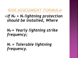
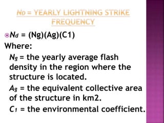
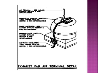
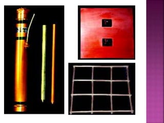
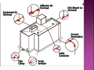
Lightning is the visible
discharge of static
electricity within a
cloud, between clouds,
or between the earth
and a cloud.
Current levels sometimes in
excess of 4000 KA,
Temperatures to 50,000
degrees F (water freezes at 32
degrees Fahrenheit under
normal conditions), and
Speed approaching one third
the speed of light (NLSI).
1. Charged clouds induce
opposite charges on the
apex of tall structures, e.g.
towers, chimneys, trees,
mountains etc.
High electrostatic stresses at the
ends of these objects then ionizes
the air, resulting in lowering the
resistance of the path between the
cloud and the object, thus allowing
a discharge to occur between them.
Hence strikes the highest or most
pointed object in the area.
2. Occurs when a sudden
potential difference
between a cloud and the
earth is established
instantly. This is induced
soon after a strike of the
first kind.
e.g. if there is a discharge
between cloud 1 and 2, cloud 3
can be suddenly left with
greater potential difference
gradient immediately adjacent
to it than the air can withstand
and a sudden strike to the
earth will occur.
Lightning risk assessment
methodology is provided
to assist the building
owner or architect /
engineer in determining
the risk of damage due to
lightning
If Nd > Nc lightning protection
should be installed, Where
Nd = Yearly lightning strike
frequency;
Nc = Tolerable lightning
frequency.
Nd = (Ng)(Ag)(C1)
Where:
Ng = the yearly average flash
density in the region where the
structure is located.
Ag = the equivalent collective area
of the structure in km2.
C1 = the environmental coefficient.
Yearly Flash density is
measured in km2/year, i.e.
flashes/km2/yr.
The data is obtained on flash
density maps.
These are obtained from the
meteorological offices,
e.g. A 10-year flash density
map
Refers to the ground area
having the same yearly
direct lightning flash
probability as the structure.
The effects of height and
location are also considered
in the area computations.
RECTANGULAR
MODEL
This accounts for the
topography of the site of
the structure and any
other objects within a
distance of 3H
Given as follows:
This is a measure of the
damage risk to the
structure including factors
affecting risks to the
structure, environment
and the monetary loss.
It is calculated as follows:
If Nd > Nc lightning protection
should be installed, Where
Nd = Yearly lightning strike
frequency
Nc = Tolerable lightning
frequency
EXAMPLE:
 Lightning flash density (Ng) = 4
 Relative structural location (C1) = 2
 Rectangular structure L = 80m
W = 50m
H = 30m
 Lightning strike frequency (Nd) = 3.93
C2=3, C3=3, C4=1, and C5=5
 Qs: Should the structure be protected
or not?
The Primary components:
Air terminals
Down conductor / cable
Ground terminals
Surge protectors
These intercept the
lightning discharge
TYPES:
Plain air terminals
Safety air terminals
Flexible air terminals
Copper
Aluminum
Class 1
Class 2
Structural steel frames
Ground rods
Plain/sectional copper clad
steel, copper, galvanized steel,
stainless steel
Ground plates
Ground mesh
Concrete encased electrodes
Reinforced steel
Copper conductors
The lightning protection
system has a zone of
protection.
A single vertical conductor
protects an area in circular
form of the building having
its center at the conductor
and reaching equal to twice
the height of the conductor.
It is however better to
provide a protection with a
zone consisting of a cone
with its apex at the top of
the vertical conductor and
a base of radius equal to
the height of the conductor.
There are basically three types
of lightning protection system
which are:
1. The simple lightning rod
2. The lightning rod with taut
wires
3. The lightning conductor with
meshed cage
1. The simple lightning rod
The lightning rod is a metallic
capture tip placed at the top
of a building, and is earthed
to the ground by one or more
down-conductors and earth
plates or crow’s feet.
2. Rod with taut wires
The tin plated copper
wires are stretched above
the structure to be
protected.
For special structures e.g.
rocket launching areas,
etc.
3. Meshed cage
This involves fixing numerous
down conductors symmetrically
all round the building.
This type is highly
recommended for highly
exposed buildings with very
sensitive installations like
computer rooms.
LIGHTINING PROTECTION.pptx

LIGHTINING PROTECTION.pptx

  • 2.
    Lightning is thevisible discharge of static electricity within a cloud, between clouds, or between the earth and a cloud.
  • 3.
    Current levels sometimesin excess of 4000 KA, Temperatures to 50,000 degrees F (water freezes at 32 degrees Fahrenheit under normal conditions), and Speed approaching one third the speed of light (NLSI).
  • 4.
    1. Charged cloudsinduce opposite charges on the apex of tall structures, e.g. towers, chimneys, trees, mountains etc.
  • 5.
    High electrostatic stressesat the ends of these objects then ionizes the air, resulting in lowering the resistance of the path between the cloud and the object, thus allowing a discharge to occur between them. Hence strikes the highest or most pointed object in the area.
  • 6.
    2. Occurs whena sudden potential difference between a cloud and the earth is established instantly. This is induced soon after a strike of the first kind.
  • 7.
    e.g. if thereis a discharge between cloud 1 and 2, cloud 3 can be suddenly left with greater potential difference gradient immediately adjacent to it than the air can withstand and a sudden strike to the earth will occur.
  • 8.
    Lightning risk assessment methodologyis provided to assist the building owner or architect / engineer in determining the risk of damage due to lightning
  • 9.
    If Nd >Nc lightning protection should be installed, Where Nd = Yearly lightning strike frequency; Nc = Tolerable lightning frequency.
  • 10.
    Nd = (Ng)(Ag)(C1) Where: Ng= the yearly average flash density in the region where the structure is located. Ag = the equivalent collective area of the structure in km2. C1 = the environmental coefficient.
  • 11.
    Yearly Flash densityis measured in km2/year, i.e. flashes/km2/yr. The data is obtained on flash density maps. These are obtained from the meteorological offices, e.g. A 10-year flash density map
  • 12.
    Refers to theground area having the same yearly direct lightning flash probability as the structure. The effects of height and location are also considered in the area computations.
  • 14.
  • 15.
    This accounts forthe topography of the site of the structure and any other objects within a distance of 3H Given as follows:
  • 17.
    This is ameasure of the damage risk to the structure including factors affecting risks to the structure, environment and the monetary loss. It is calculated as follows:
  • 23.
    If Nd >Nc lightning protection should be installed, Where Nd = Yearly lightning strike frequency Nc = Tolerable lightning frequency
  • 24.
    EXAMPLE:  Lightning flashdensity (Ng) = 4  Relative structural location (C1) = 2  Rectangular structure L = 80m W = 50m H = 30m  Lightning strike frequency (Nd) = 3.93 C2=3, C3=3, C4=1, and C5=5  Qs: Should the structure be protected or not?
  • 25.
    The Primary components: Airterminals Down conductor / cable Ground terminals Surge protectors
  • 26.
    These intercept the lightningdischarge TYPES: Plain air terminals Safety air terminals Flexible air terminals
  • 30.
  • 32.
    Ground rods Plain/sectional copperclad steel, copper, galvanized steel, stainless steel Ground plates Ground mesh Concrete encased electrodes Reinforced steel Copper conductors
  • 34.
    The lightning protection systemhas a zone of protection. A single vertical conductor protects an area in circular form of the building having its center at the conductor and reaching equal to twice the height of the conductor.
  • 35.
    It is howeverbetter to provide a protection with a zone consisting of a cone with its apex at the top of the vertical conductor and a base of radius equal to the height of the conductor.
  • 36.
    There are basicallythree types of lightning protection system which are: 1. The simple lightning rod 2. The lightning rod with taut wires 3. The lightning conductor with meshed cage
  • 37.
    1. The simplelightning rod The lightning rod is a metallic capture tip placed at the top of a building, and is earthed to the ground by one or more down-conductors and earth plates or crow’s feet.
  • 40.
    2. Rod withtaut wires The tin plated copper wires are stretched above the structure to be protected. For special structures e.g. rocket launching areas, etc.
  • 42.
    3. Meshed cage Thisinvolves fixing numerous down conductors symmetrically all round the building. This type is highly recommended for highly exposed buildings with very sensitive installations like computer rooms.