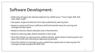
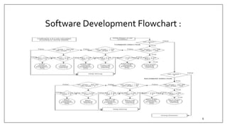
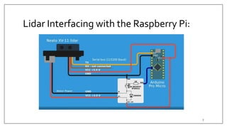
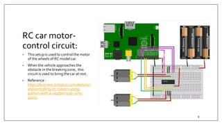
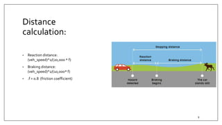
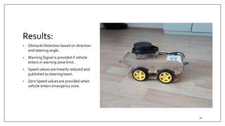
EMBEDDED RESEARCH PROJECT
LIDAR BASED OBSTACLE DETECTION
March 2019 – June 2019
Vishal Mishra
1
Introduction:
• Behavior of vehicle is determined by Lidar Laser Readings.
• Depending on speed and steering angle , obstacle detection is determined by the
vehicle.
• Two thresholds zones are defined by the system. First is warning and the second is
emergency breaking zone.
• The extremities of zone is dependent upon the vehicle speed. For example : if
vehicle is moving at a lower speed, nearby obstacles are detected and if the
vehicle is moving at a higher speed , far distance obstacles are also detected.
2
Challenges :
• XV11 Lidar Interfacing with Raspberry Pi on ROS platform
• Processing the XV11 laser data into an understandable format.
• Determination of DynamicWarning and Emergency Zones ranges depending on
Vehicle Speed
• Development of Motor Control Unit for RC model Car
• Developing a complete Dynamic System on ROS platform
3
Vehicle Control Planning:
• Check the lidar data for obstacle in your field of view
• Depending on speed, direction of the car and especially on the steering angle,
decide whether or not the object blocks your vehicle
• Provide two thresholds: t1 for warning distance, t2 for emergency break assist
• If the distance above is lower than t1, set a warning signal (e.g. yellow light or low
beep)
• If the distance above is lower than t2, set an emergency break signal (e.g. yellow
light or low beep) (the signal can be used by the steering project above)
• Test and validate on RC model car (either simple warning signal or in combination
with the steering project above)
4
Software Development:
• Define the all regions for obstacle detection by LIDAR sensor “ front, fright, fleft, left,
back, bleft, bright
• Get speed , Angle and direction from topic published by steering team
• Based on speed and friction coefficient will find threshold values for warning and
emergency brake signal.
• Based on direction detect obstacles only in that direction.
• Based on steering angle, detect obstacles in that range
• Once the vehicle is in warning zone, publish reduced speed values to steering team and
glow aYELLOW LED indicating an approaching obstacle.
• Once the vehicle is in emergency zone, publish Zero speed value to steering team for
emergency brake and glow the RED LED .
5
Software Development Flowchart :
6
Lidar Interfacing with the Raspberry Pi:
7
RC car motor-
control circuit:
• This setup is used to control the motor
of the wheels of RC model car.
• When the vehicle approaches the
obstacle in the breaking zone, this
circuit is used to bring the car at rest.
• Reference :
https://business.tutsplus.com/de/tutori
als/controlling-dc-motors-using-
python-with-a-raspberry-pi--cms-
20051
8
Distance
calculation:
• Reaction distance:
(veh_speed)^2/(20,000 * f)
• Braking distance:
(veh_speed)^2/(10,000* f)
• .f = 0.8 (friction coefficient)
9
Results:
• Obstacle Detection based on direction
and steering angle.
• Warning Signal is provided if vehicle
enters in warning zone limit.
• Speed values are linearly reduced and
published to steering team.
• Zero Speed values are provided when
vehicle enters emergency zone.
10
SampleVideo:
Hochschule RavensburgWeingarten- Master EMM 11
THANKYOU !!
Hochschule RavensburgWeingarten- Master EMM 12

Lidar based obstacle_detection_vishal_mishra

  • 1.
    EMBEDDED RESEARCH PROJECT LIDARBASED OBSTACLE DETECTION March 2019 – June 2019 Vishal Mishra 1
  • 2.
    Introduction: • Behavior ofvehicle is determined by Lidar Laser Readings. • Depending on speed and steering angle , obstacle detection is determined by the vehicle. • Two thresholds zones are defined by the system. First is warning and the second is emergency breaking zone. • The extremities of zone is dependent upon the vehicle speed. For example : if vehicle is moving at a lower speed, nearby obstacles are detected and if the vehicle is moving at a higher speed , far distance obstacles are also detected. 2
  • 3.
    Challenges : • XV11Lidar Interfacing with Raspberry Pi on ROS platform • Processing the XV11 laser data into an understandable format. • Determination of DynamicWarning and Emergency Zones ranges depending on Vehicle Speed • Development of Motor Control Unit for RC model Car • Developing a complete Dynamic System on ROS platform 3
  • 4.
    Vehicle Control Planning: •Check the lidar data for obstacle in your field of view • Depending on speed, direction of the car and especially on the steering angle, decide whether or not the object blocks your vehicle • Provide two thresholds: t1 for warning distance, t2 for emergency break assist • If the distance above is lower than t1, set a warning signal (e.g. yellow light or low beep) • If the distance above is lower than t2, set an emergency break signal (e.g. yellow light or low beep) (the signal can be used by the steering project above) • Test and validate on RC model car (either simple warning signal or in combination with the steering project above) 4
  • 5.
    Software Development: • Definethe all regions for obstacle detection by LIDAR sensor “ front, fright, fleft, left, back, bleft, bright • Get speed , Angle and direction from topic published by steering team • Based on speed and friction coefficient will find threshold values for warning and emergency brake signal. • Based on direction detect obstacles only in that direction. • Based on steering angle, detect obstacles in that range • Once the vehicle is in warning zone, publish reduced speed values to steering team and glow aYELLOW LED indicating an approaching obstacle. • Once the vehicle is in emergency zone, publish Zero speed value to steering team for emergency brake and glow the RED LED . 5
  • 6.
  • 7.
    Lidar Interfacing withthe Raspberry Pi: 7
  • 8.
    RC car motor- controlcircuit: • This setup is used to control the motor of the wheels of RC model car. • When the vehicle approaches the obstacle in the breaking zone, this circuit is used to bring the car at rest. • Reference : https://business.tutsplus.com/de/tutori als/controlling-dc-motors-using- python-with-a-raspberry-pi--cms- 20051 8
  • 9.
    Distance calculation: • Reaction distance: (veh_speed)^2/(20,000* f) • Braking distance: (veh_speed)^2/(10,000* f) • .f = 0.8 (friction coefficient) 9
  • 10.
    Results: • Obstacle Detectionbased on direction and steering angle. • Warning Signal is provided if vehicle enters in warning zone limit. • Speed values are linearly reduced and published to steering team. • Zero Speed values are provided when vehicle enters emergency zone. 10
  • 11.
  • 12.