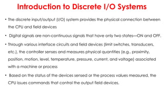
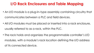
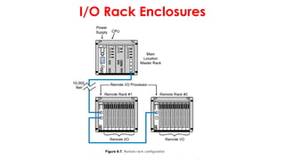
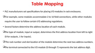
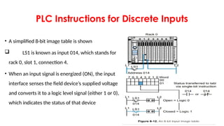
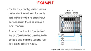
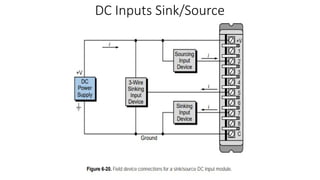
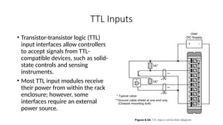
PLC COURSE
Lecture4
Title of this lecture
Discrete Input/Output System
Introduction to Discrete I/O Systems
• The discrete input/output (I/O) system provides the physical connection between
the CPU and field devices
• Digital signals are non-continuous signals that have only two states—ON and OFF.
• Through various interface circuits and field devices (limit switches, transducers,
etc.), the controller senses and measures physical quantities (e.g., proximity,
position, motion, level, temperature, pressure, current, and voltage) associated
with a machine or process
• Based on the status of the devices sensed or the process values measured, the
CPU issues commands that control the output field devices.
I/O Rack Enclosures and Table Mapping
• An I/O module is a plug-in–type assembly containing circuitry that
communicates between a PLC and field devices.
• All I/O modules must be placed or inserted into a rack enclosure,
usually referred to as a rack, within the PLC.
• The rack holds and organizes the programmable controller’s I/O
modules, with a module’s rack location defining the I/O address
of its connected device.
I/O Rack Enclosures and Table Mapping
• The I/O address is a unique number that identifies the
input/output device during control program setup and execution.
• A rack recognizes the type of module connected to it (input or
output) and the class of interface (discrete, analog, numerical,
etc.).
• This module recognition is decoded on the back plane (i.e., the
printed circuit board containing the data bus, power bus, and
mating connectors) of the rack
I/O Rack Enclosures
I/O Rack Enclosures
I/O Rack Enclosures
Table Mapping
• PLC manufacturers set specifications for placing I/O modules in rack enclosures.
For example, some modules accommodate 2 to 16 field connections, while other modules
require the user to follow certain I/O addressing regulations.
• Several factors determine the address location of each module.
The type of module, input or output, determines the first address location from left to right
(0 for outputs, 1 for inputs).
The rack number and slot location of the module determine the next two address numbers.
The terminal connected to the I/O module (0 through 7) represents the last address digit.
I/O Rack and Table Mapping Example
I/O Racks and Mapping
• The capacity of a single subsystem (rack) is normally 32,
64, 128, or 256 I/O points.
• A large system with a maximum capacity of 1024 I/O
points may have subsystem sizes of either 64 or 128 points
—eight racks with 128 I/O, sixteen racks with 64 I/O, or
some combination of both sizes equal to 1024 I/O
I/O Modules serve four basic functions
• Termination
• Signal Conditioning
• Isolation
• Indication
I/O Module Selection
• Type of current (AC or DC)
• Voltage Level
• Number of terminals
PLC Instructions for Discrete Inputs
• A simplified 8-bit image table is shown
 LS1 is known as input 014, which stands for
rack 0, slot 1, connection 4.
• When an input signal is energized (ON), the input
interface senses the field device’s supplied voltage
and converts it to a logic level signal (either 1 or 0),
which indicates the status of that device
EXAMPLE
• For the rack configuration shown,
determine the address for each
field device wired to each input
connection in the 8-bit discrete
input module.
• Assume that the first four slots of
this 64 I/O microPLC are filled with
outputs and that the second four
slots are filled with inputs.
Example
PLC Instructions for Discrete Inputs
• The most common class of
input interfaces is digital (or
discrete).
• Digital input interfaces have
only two states
ON/OFF
OPEN/CLOSED
 TRUE/FALSE
• Those states signify either 1 or
0.
Circuit Breaker
• circuit breaker is an automatically operated
electrical switch designed to protect an
electrical circuit from damage caused by
overload or short circuit.
• Unlike a fuse, which operates once and then
has to be replaced, a circuit breaker can be
reset (either manually or automatically) to
resume normal operation
Types of Discrete Inputs
AC/DC Inputs
• An AC/DC input circuit has two primary parts:
 the power section
 the logic section
• These sections are normally, but not always, coupled through a circuit that electrically separates them,
providing isolation.
AC/DC Inputs
DC Inputs Sink/Source
• Compared with AC/DC modules, the DC input does not contain a bridge circuit.
• DC input module varies between 5 and 30 VDC.
If a device provides current when it is ON, it is said to be sourcing current.
If a device receives current when it is ON, it is said to be sinking current.
• The most common are sourcing field input devices and sinking input modules.
DC Inputs Sink/Source
TTL Inputs
• Transistor-transistor logic (TTL)
input interfaces allow controllers
to accept signals from TTL-
compatible devices, such as solid-
state controls and sensing
instruments.
• Most TTL input modules receive
their power from within the rack
enclosure; however, some
interfaces require an external
power source.
Register / BCD Inputs
Assignment4-1
• Write a report about the following discrete input devices
Assignment4-2
Write a report about the PLC Instructions for Discrete Outputs?
Use “Programmable Controllers: Theory and Implementation by Bryan
and Bryan” REFRENCE

lecture4 discrete input/output system.pptx

  • 1.
    PLC COURSE Lecture4 Title ofthis lecture Discrete Input/Output System
  • 2.
    Introduction to DiscreteI/O Systems • The discrete input/output (I/O) system provides the physical connection between the CPU and field devices • Digital signals are non-continuous signals that have only two states—ON and OFF. • Through various interface circuits and field devices (limit switches, transducers, etc.), the controller senses and measures physical quantities (e.g., proximity, position, motion, level, temperature, pressure, current, and voltage) associated with a machine or process • Based on the status of the devices sensed or the process values measured, the CPU issues commands that control the output field devices.
  • 3.
    I/O Rack Enclosuresand Table Mapping • An I/O module is a plug-in–type assembly containing circuitry that communicates between a PLC and field devices. • All I/O modules must be placed or inserted into a rack enclosure, usually referred to as a rack, within the PLC. • The rack holds and organizes the programmable controller’s I/O modules, with a module’s rack location defining the I/O address of its connected device.
  • 4.
    I/O Rack Enclosuresand Table Mapping • The I/O address is a unique number that identifies the input/output device during control program setup and execution. • A rack recognizes the type of module connected to it (input or output) and the class of interface (discrete, analog, numerical, etc.). • This module recognition is decoded on the back plane (i.e., the printed circuit board containing the data bus, power bus, and mating connectors) of the rack
  • 5.
  • 7.
  • 8.
  • 9.
    Table Mapping • PLCmanufacturers set specifications for placing I/O modules in rack enclosures. For example, some modules accommodate 2 to 16 field connections, while other modules require the user to follow certain I/O addressing regulations. • Several factors determine the address location of each module. The type of module, input or output, determines the first address location from left to right (0 for outputs, 1 for inputs). The rack number and slot location of the module determine the next two address numbers. The terminal connected to the I/O module (0 through 7) represents the last address digit.
  • 12.
    I/O Rack andTable Mapping Example
  • 13.
    I/O Rack andTable Mapping Example
  • 14.
    I/O Rack andTable Mapping Example
  • 15.
    I/O Racks andMapping • The capacity of a single subsystem (rack) is normally 32, 64, 128, or 256 I/O points. • A large system with a maximum capacity of 1024 I/O points may have subsystem sizes of either 64 or 128 points —eight racks with 128 I/O, sixteen racks with 64 I/O, or some combination of both sizes equal to 1024 I/O
  • 16.
    I/O Modules servefour basic functions • Termination • Signal Conditioning • Isolation • Indication
  • 17.
    I/O Module Selection •Type of current (AC or DC) • Voltage Level • Number of terminals
  • 18.
    PLC Instructions forDiscrete Inputs • A simplified 8-bit image table is shown  LS1 is known as input 014, which stands for rack 0, slot 1, connection 4. • When an input signal is energized (ON), the input interface senses the field device’s supplied voltage and converts it to a logic level signal (either 1 or 0), which indicates the status of that device
  • 19.
    EXAMPLE • For therack configuration shown, determine the address for each field device wired to each input connection in the 8-bit discrete input module. • Assume that the first four slots of this 64 I/O microPLC are filled with outputs and that the second four slots are filled with inputs.
  • 20.
  • 21.
    PLC Instructions forDiscrete Inputs • The most common class of input interfaces is digital (or discrete). • Digital input interfaces have only two states ON/OFF OPEN/CLOSED  TRUE/FALSE • Those states signify either 1 or 0.
  • 22.
    Circuit Breaker • circuitbreaker is an automatically operated electrical switch designed to protect an electrical circuit from damage caused by overload or short circuit. • Unlike a fuse, which operates once and then has to be replaced, a circuit breaker can be reset (either manually or automatically) to resume normal operation
  • 23.
  • 24.
    AC/DC Inputs • AnAC/DC input circuit has two primary parts:  the power section  the logic section • These sections are normally, but not always, coupled through a circuit that electrically separates them, providing isolation.
  • 25.
  • 26.
    DC Inputs Sink/Source •Compared with AC/DC modules, the DC input does not contain a bridge circuit. • DC input module varies between 5 and 30 VDC. If a device provides current when it is ON, it is said to be sourcing current. If a device receives current when it is ON, it is said to be sinking current. • The most common are sourcing field input devices and sinking input modules.
  • 27.
  • 28.
  • 30.
    TTL Inputs • Transistor-transistorlogic (TTL) input interfaces allow controllers to accept signals from TTL- compatible devices, such as solid- state controls and sensing instruments. • Most TTL input modules receive their power from within the rack enclosure; however, some interfaces require an external power source.
  • 32.
  • 33.
  • 34.
  • 35.
    Assignment4-1 • Write areport about the following discrete input devices
  • 36.
    Assignment4-2 Write a reportabout the PLC Instructions for Discrete Outputs? Use “Programmable Controllers: Theory and Implementation by Bryan and Bryan” REFRENCE