This document provides guidance for conducting sanitary surveys of drinking water systems. It covers organizing and completing a sanitary survey, relevant regulations, assessing various water source types (groundwater and surface water), water treatment and storage facilities, distribution systems, cross connections, process control monitoring, and utility management. The document contains learning objectives, data collection requirements, and potential significant deficiencies for each topic. It is designed to assist in delivering sanitary survey training.


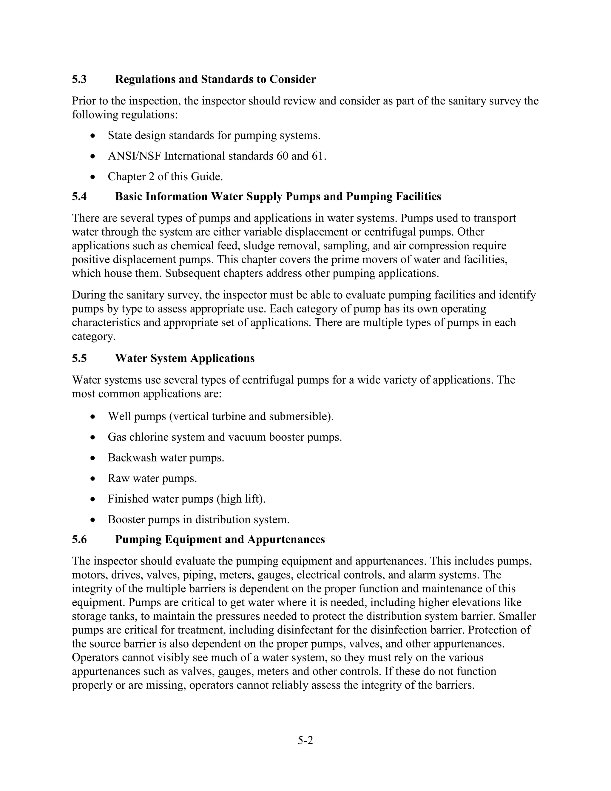
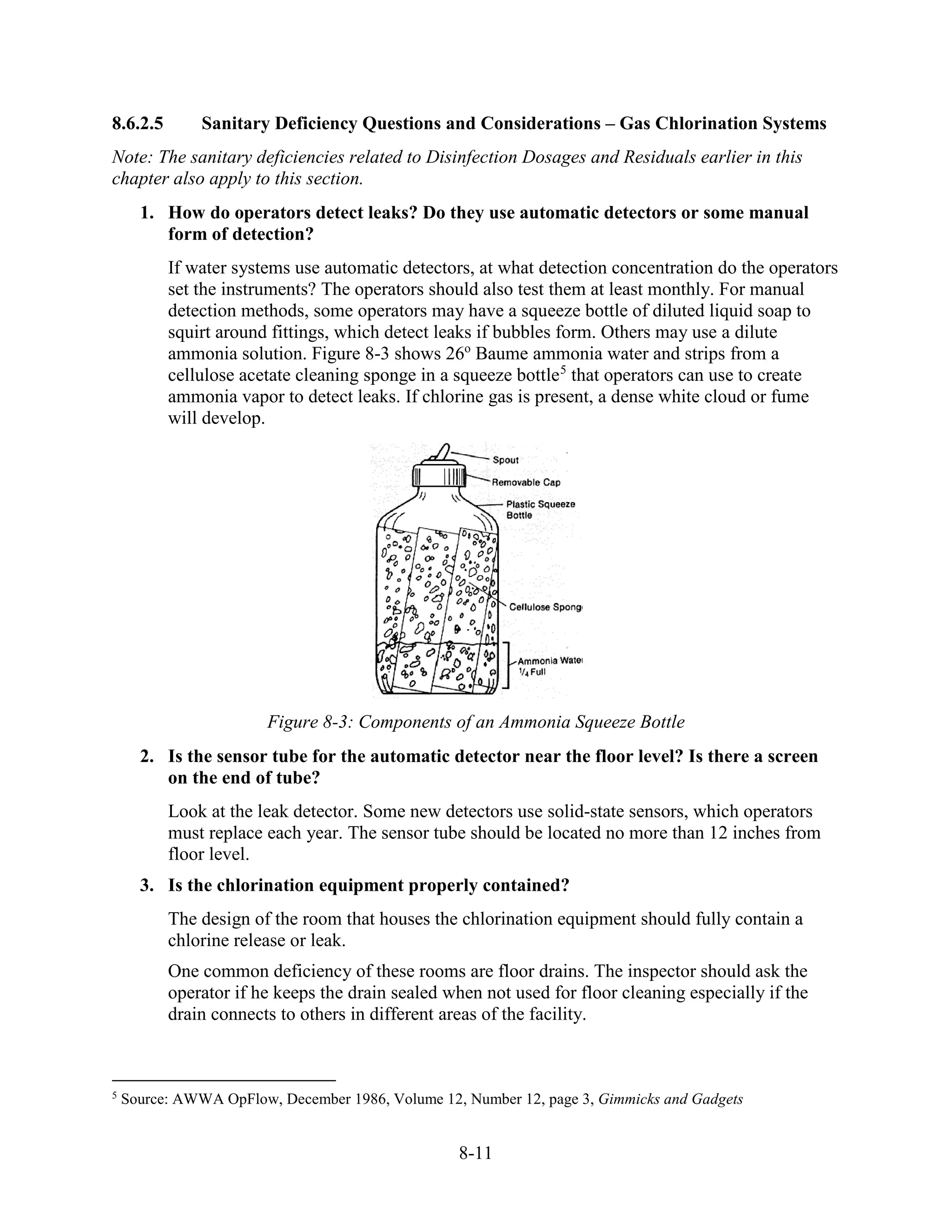
![7-2
7.2.3 Physical Facilities Information
The inspector needs to evaluate the following regarding the system’s physical facilities:
• Buildings and rooms where treatment processes are located, with respect to accessibility,
safety, and overall maintenance.
• Operation, maintenance and design of treatment units.
7.3 Regulations and Standards to Consider
The inspector needs to consider and review the following information prior to the inspection:
• Chapter 2 of this Guide.
• Specific regulations that apply to the facility.
• Past inspection reports to identify previous compliance problems.
7.4 Purpose of Water Treatment
The purpose of water treatment is to condition, modify, or remove undesirable impurities or
pathogens in order to provide water that is safe, palatable, and acceptable to consumers. National
standards for some of the impurities considered important to the health of consumers are set
under the federal Safe Drinking Water Act (specified in 40 CFR Part 141 with maximum
contaminant levels [MCLs] and treatment techniques). If the levels of contaminants present
exceed the established MCLs, water systems must treat the water to reduce the levels.
Regulations specify treatment techniques when MCLs are not appropriate for public health
protection.
Title 40 CFR Part 143 establishes secondary standards for some impurities that affect the
aesthetic qualities of water. These standards are not enforceable by the federal government, but
states may choose to adopt and enforce them. Treatment or modification of the water to comply
with secondary standards is highly recommended because consumers may seek out unsafe
sources if the drinking water supplied by the public system has an undesirable appearance, taste,
or odor.
7.5 Removal Processes
The types of chemical removal processes covered in this section include:
• Reverse osmosis.
• Corrosion control.
• Iron and manganese removal.
• Organics removal.
• Aeration.
• Water softening.](https://image.slidesharecdn.com/421ba492-4b69-4a83-ad78-5a5bcd79ac56-160607213814/75/LearnersGuide_Released-9-11-126-2048.jpg)


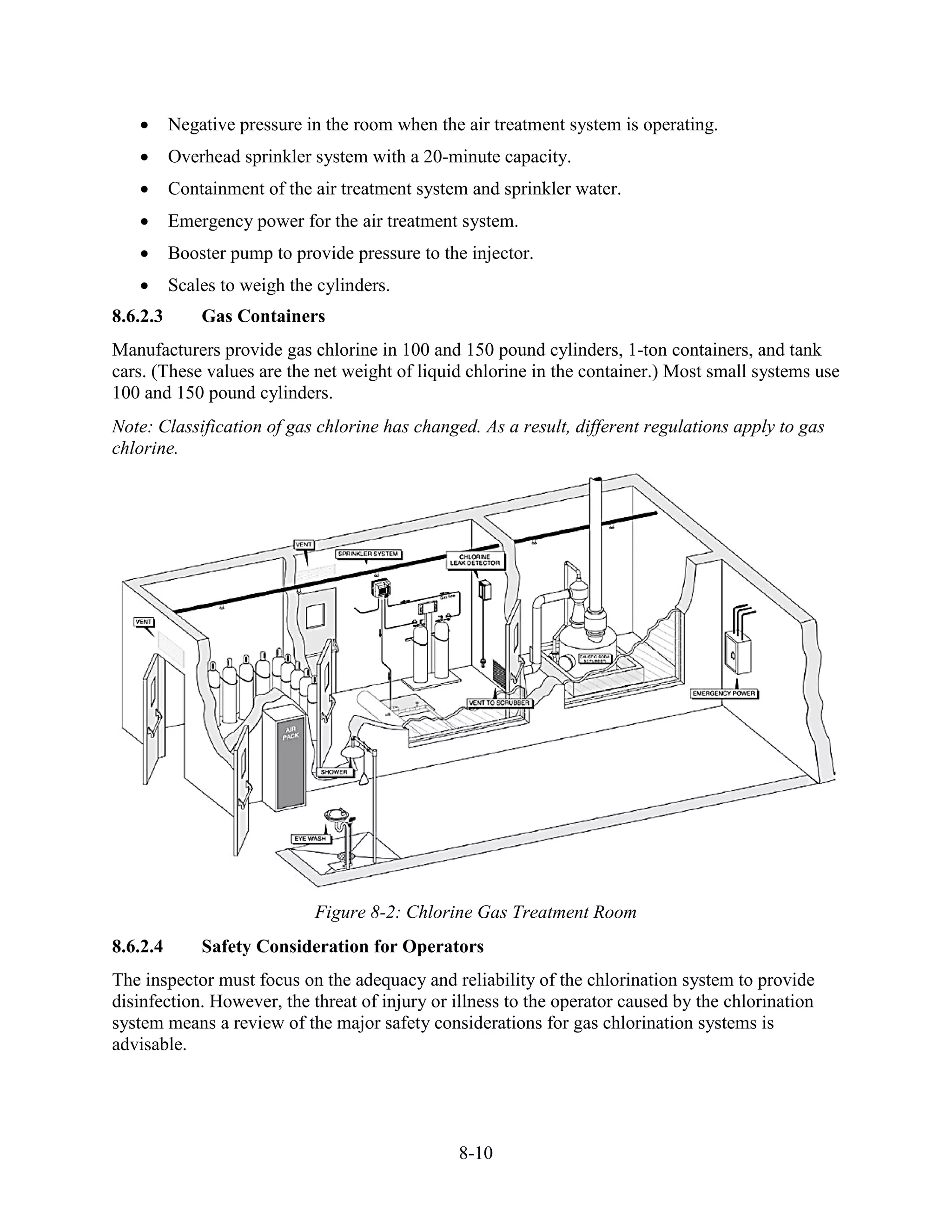
![8-12
4. Is the chlorination room vented at floor level with an adequate make-up air supply
coming from the ceiling across the room? Where is the vent switch located?
The inspector should determine if the design of the air exhaust and intake systems
provide a slight negative pressure in the chlorine room when the air ventilation system is
operating. A switch on the outside of the door allows the operator to turn on the air
handling system prior to entry. The ventilation system may also be automatically
activated when the door is opened or when the light is turned on.
Many organizations have classified chlorine rooms as confined spaces. [Note: Do not
enter if you are not sure that the air handling system is operating properly.]
5. Does the door in the chlorination room open out and have a panic bar and a
window?
The panic bar and outward-opening door are operator safety concerns and not a direct
sanitary deficiency. The window allows the operator to observe the conditions in the
chlorine room without entry, thus reducing exposure to hazardous conditions.
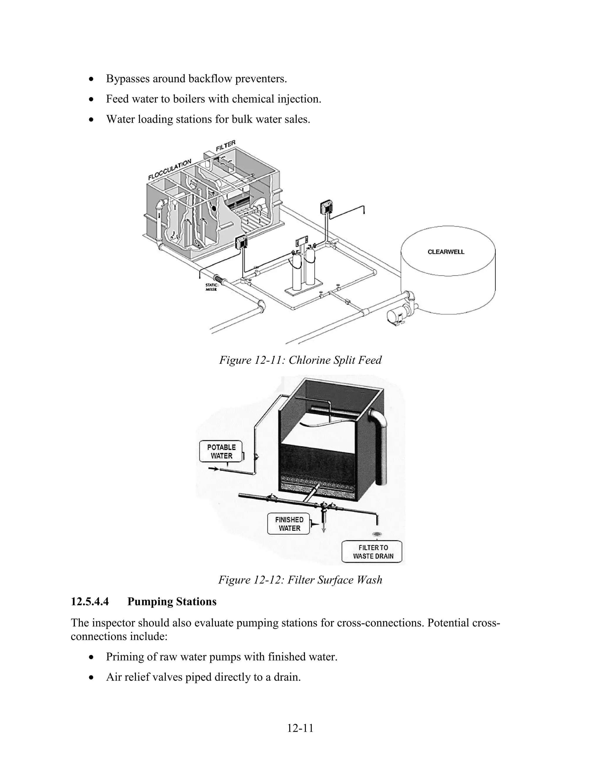
6. Are there any cross-connections in the chlorine feed make-up water or injection
points?
A common cross-connection problem in chlorination facilities is a drinking water
connection to the injector and the make-up water for hypochlorination systems. There
must be a physical separation or an acceptable backflow preventer between the drinking
water system and the feed water to the injector.
7. Is there an alarm tied to interruptions in the chlorine feed?
Low system vacuum and low cylinder pressure are the two most common alarm systems.
If there is an alarm system, does it work? Does the system shut down the flow of water,
or just initiate an alarm?
8. Does the system use automation, pace with flow, chlorine residual analyzer, or other
system to adjust feed rates? Does it work?
Finding automatic equipment that does not work is fairly common. Determine whether
the system provides adequate residual during high flows and whether the residuals are
higher during low flows. Failure of the system to dose according to varying flow rates is
a significant sanitary deficiency.
9. Is there more than one cylinder, and are they equipped with a manifold and an
automatic switch-over to avoid running out of chlorine?
The inspector should determine whether the switch-over devices work. If there is only
one cylinder, determine if the operator shuts off water flow when the cylinder is changed.
Failure to shut off the flow of water interrupts disinfection.
10. Are the cylinders on a working scale?
Operators must use a scale to determine the amount of chlorine used each day. To
calculate dosage and signal the amount of chlorine remaining in the cylinders, operators
must also routinely maintain and calibrate the scales.](https://image.slidesharecdn.com/421ba492-4b69-4a83-ad78-5a5bcd79ac56-160607213814/75/LearnersGuide_Released-9-11-156-2048.jpg)
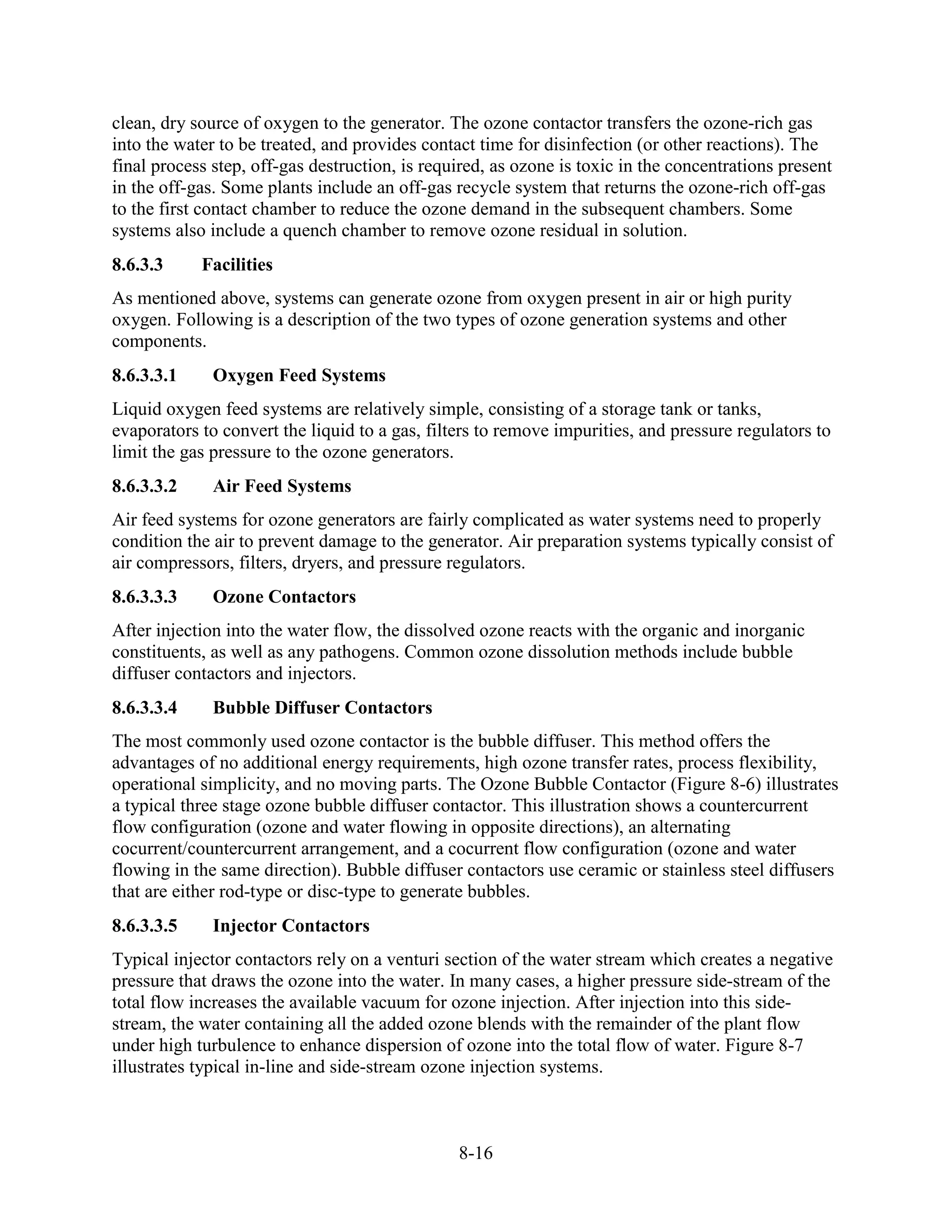
![8-19
The typical locations for feeding ozone in a water treatment plant are at the head of the
treatment plant (raw water) pre-ozonation and after sedimentation.
7. How is ozone inactivation (CT) determined?
There are several methods of determining ozone inactivation credit. The methods differ
in the level of effort needed and in the ozone dose needed to achieve a level of
inactivation. The operator should be able to explain the method used, as well as the
contactor sampling locations used in inactivation calculations. Methods for determining
ozone inactivation are included in the EPA SWTR Guidance Manual and in the EPA Long
Term 2 Enhanced Surface Water Treatment Rule Toolbox Guidance Manual.
8. Does the utility have an operation and maintenance plan for the ozone system?
Even though ozone systems are complex, using highly technical instruments, the process
is highly automated and very reliable. Maintenance on generators requires skilled
technicians. Operators should check generators daily, when in operation and periodically
change filters and desiccant in air preparation systems, where the frequency depends on
the quality of the inlet air and the number of hours in operation. Compressors require
periodic service, depending on the type and operating time.
Certified professionals should periodically pressure test liquid oxygen tanks as well. Ask
the operator how often they inspect piping and contact chambers for leaks and corrosion
and how often they clean the dielectric tubes. The water system should have procedures
in place and provide the equipment needed for cleaning operations as well as storage
space for spare tubes.
9. Is the utility complying with the MCL for bromide and the monitoring requirements
under the D/DBPR?
Ozone does not form halogenated Disinfectants and Disinfection Byproducts (D/DBPs-
[THM and HAA ]) in reactions with natural organic matter, but it does form a variety of
organic and inorganic byproducts. However, if bromide ions are present in the raw water,
ozone may react with them to form halogenated DBPs. Therefore, the rule requires water
systems, community and non-transient/non-community, using ozone for disinfection or
oxidation to monitor for bromate.
10. Has management provided for the safety of the operators responsible for the
operation and maintenance of all ozonation processes?
The water system is responsible for providing necessary instrumentation for ozone
systems to protect both personnel and the equipment such as gas phase ozone detectors
installed in generator rooms, where ozone gas may exist and personnel are routinely
present. Systems should also have an ozone detector installed on the outlet from the off-
gas destruct unit, to ensure the unit is working properly.
8.6.4 Disinfection with Ultraviolet Light
8.6.4.1 Introduction
The use of UV for disinfection of drinking water continues to grow in public water systems, due
to its ability to inactivate pathogenic microorganisms without forming regulated disinfection](https://image.slidesharecdn.com/421ba492-4b69-4a83-ad78-5a5bcd79ac56-160607213814/75/LearnersGuide_Released-9-11-163-2048.jpg)