Download to read offline
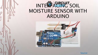
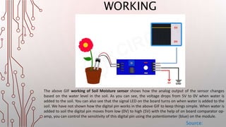
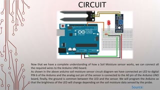
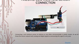
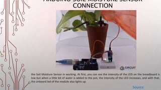


The document details the interfacing of a soil moisture sensor with an Arduino, outlining the components, connections, and functionality. The sensor includes a probe and an electronic module that communicates with the Arduino to measure soil moisture levels, affecting output signals. As soil moisture changes, the LED brightness linked to the sensor adjusts accordingly, demonstrating the setup's operation.


