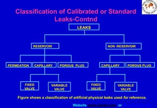
Website www.sisndt.com orwww.ndtsis.com
CHAPTER 1
INTRODUCTION
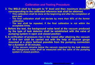
Non-destructive testing (NDT) has no clearly defined boundaries. A
simple technique such as a visual inspection is a form of non-
destructive testing method. Major methods include:
1. Penetrant testing
2. Magnetic particle testing
3. Ultrasonic testing
4. Radiography testing
There are also ranges of other new techniques that have particular
specialized applications in limited fields. They include
5. Eddy current testing
6. Acoustic emission methods
7. Thermography
8. Holography
9. Leak testing
2.
Website www.sisndt.com orwww.ndtsis.com
Development of leak testing applications
• Until recent years, leak testing of most objects was performed in a
relatively crude manner.
• The entire field had been greatly ignored by many groups with the
exception of the American Vacuum Society.
• Out of necessity, this group provided the initial impetus that is now
growing at a rapid rate.
• Leakage has now become a serious concern in the fabrication of
nuclear reactor components, unfired pressure vessels and vessels
containing lethal substances.
• Leak testing is also used on other components or systems utilized in
processing of fluid materials that are affected by the presence of
contaminants that react with the product.
• Leak tests are now made on pyrotechnic devices, electronic
components, automotive air conditioners, food packages, and other
test objects described in this volume.
3.
Website www.sisndt.com orwww.ndtsis.com
Leak Testing Objectives
• Like other forms of nondestructive testing, leak testing has a great
impact on the safety or performance of a product.
• Reliable leak testing saves costs by reducing the number of reworked
products, warranty repairs and liability claims.
• The time and money invested in leak testing often produces
immediate profit.
• The three most common reasons for performing a leak test are:
• MATERIAL LOSS
• CONTAMINATION
• RELIABILITY
4.
Website www.sisndt.com orwww.ndtsis.com
CHAPTER 2
INTRODUCTION TO LEAK TESTING
• Leak Testing is the branch of nondestructive testing that is
concerned with the escape of liquids, vacuum or gases from sealed
components or systems.
• This article will cover the reasons for leak testing and some of the
technology behind the science.
• The major leak testing methods will be surveyed on the basis of how
to select the proper method.
• A brief description of how to establish a leak test specification is
included.
5.
Website www.sisndt.com orwww.ndtsis.com
Need for Leak Testing
• Leak testing is one of the non-destructive testing methods used
i. for detection and location of leaks and
ii. for the measurement of fluid leakage in either pressurized or evacuated
systems and components as a result of a pressure differential between
the two regions.
• The word “leak” refers to the physical hole that exists and does not
refer to the quantity of fluid passing through that hole.
• A leak may be a crack, crevice, fissure, hole or passageway that
admits fluids or lets fluid escape.
• The word “leakage” refers to the flow of fluid through a leak without
regard to the physical size of the hole through which flow occurs.
• “Leakage rate”, refers to the rate of fluid flow per unit of time under a
given set of conditions, and is expressed in units of mass per unit of
time.
6.
Website www.sisndt.com orwww.ndtsis.com
Need for Leak Testing
Leaks are special type of flaws that can have tremendous importance
where they influence the safety or performance of engineering
system. Leak testing is performed for three basic reasons:
1. To prevent material leakage loss, which interferes with system
operation
2. To prevent environmental contamination hazards caused by
accidental leakage
3. To detect unreliable components and those whose leakage rates
exceed acceptance standards.
The end purpose of leak testing is to ensure reliability and serviceability
of components and to prevent premature failure of systems
containing fluids under pressure or vacuum.
7.
Website www.sisndt.com orwww.ndtsis.com
Need for Leak Testing
• The term “minimum detectable leak” refers to the smallest hole or
discrete passage that can be detected and “minimum detectable
leakage rate” refers to the smallest detectable fluid-flow rate,
generally known as sensitivity of the test system.
• The sensitivity of the instrument is the amount of leakage required for
a leak testing instrument to give a minimum detectable signal.
• The sensitivity of the test depends on existing conditions of pressure,
temperature and fluid flow.
8.
Website www.sisndt.com orwww.ndtsis.com
Need for Leak Testing
• Leakage may occur from any location within a component, assembly,
or system to its outside boundary or from external regions to points
within a volume enclosed by pressure boundary.
• When a fluid flows through a leak, the leakage flow rate depends
upon:
1. The geometry of the leak
2. The nature of the leak fluid and
3. The prevailing condition of the fluid pressure, temperature and type
of flow.
• For leak testing purposes, as easily detectable gas or fluid may be
used rather than air or operating fluid.
• The leakage occurs as a result of pressure differential between two
regions, separated by pressure boundary.
• The leakage rate is some times referred to as mass flow rate. In the
case of the leakage of gas, the leakage rate describes the number of
molecules leaking for unit of time, if the gas temperature is constant.
9.
Website www.sisndt.com orwww.ndtsis.com
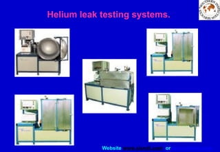
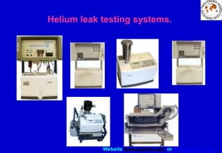
Industrial applications of Helium Leak Test
• In some cases an examination for overall leak detection is performed
first, and if leaks are detected, the localizing method is applied for
pinpointing of the leak.
• This is however not always required nor possible.
• Secondly it is necessary to determine the leak rate which can be
tolerated, as no objects are 100% tight. That is the requirements to
tightness of the object.
• If for example the object have to be watertight, a leak rate below 10-4
mbar l/s will be sufficient.
• But if the object for example is to be used in the chemical industry the
requirements can be a leak rate below 10-6
mbar l/s.
10.
Website www.sisndt.com orwww.ndtsis.com
Industrial applications of Helium Leak Test
• In leak testing a pressure difference between the outer and the inner
side of the object to be examined is produced.
• Subsequently the amount of gas or liquid which is passing through a
leak is measured.
• In helium leak test helium is used as a search gas, from this the
nomination of the method.
• In principle two methods are applied for leak testing and localisation
of leaks, the "Vacuum method" and the "Overpressure method".
• At the "Vacuum method" the object to be examined for leaks is
evacuated and sprayed from the outside with a search gas, in this
case Helium.
• The gas enters through any leaks present in the object and is
detected by a sensor connected to the leak test instrument.
11.
Website www.sisndt.com orwww.ndtsis.com
Industrial applications of Helium Leak Test
• At the "Overpressure method" the object to be examined for leaks is
filled with a search gas, Helium, under slight overpressure. The
search gas escapes through any leaks present to the outside and is
detected by a detector probe. This detector probe is in most cases
called a "sniffer" acting as a gas sampling probe.
12.
Website www.sisndt.com orwww.ndtsis.com
Customer requirements in research and
industry
• Changes in the main requirements on leak detectors in the transition
from research to industry applications
13.
Website www.sisndt.com orwww.ndtsis.com
Customer requirements in research and
industry
• Realization of main requirements in modern helium leak detectors
14.
Website www.sisndt.com orwww.ndtsis.com
CHAPTER 2
INTRODUCTION TO LEAK TESTING
QUESTIONAIRE
1. The physical hole is represented by the word
A. Leak
B. Leakage
C. Leakage rate
D. All of the above
E. None of the above
2. Leak testing is used
F. To prevent material loss
G. To prevent contamination and hazard
H. To distinguish between reliable and non reliable components
I. All of the above
J. None of the above
15.
Website www.sisndt.com orwww.ndtsis.com
INTRODUCTION TO LEAK TESTING
QUESTIONAIRE
3. Sensitivity means
A. Minimum detectable signal
B. Maximum detectable signal
C. Average detectable signal
D. optimum detectable signal
4. Instrument sensitivity of the test depends on
E. pressure condition
F. temperature
G. liquid flow
H. all of the above
I. none of the above
16.
Website www.sisndt.com orwww.ndtsis.com
INTRODUCTION TO LEAK TESTING
QUESTIONAIRE
5. Leakage flow rate depend on
A. Geometry of the leak
B. nature of the leak fluid
C. type of flow
D. all of the above
E. none of the above
17.
Website www.sisndt.com orwww.ndtsis.com
CHAPTER 3
PROPERTIES OF GASEOUS TRACERS
• Fluid Media Used in Leak Testing
• Volumes Occupied by Gases and by Liquids
• Pressures Exerted by Gases or Liquids
18.
Website www.sisndt.com orwww.ndtsis.com
Fluid Media Used in Leak Testing
• Leak testing can be divided into three categories:
1.leak detection,
2.leak location, and
3.Leakage measurement.
• Each method involves use of a fluid leak tracer and some
means for establishing a pressure differential or other
means for causing fluid flow through the leak or Leaks.
• Possible fluid media include gases, vapors, and liquids or
combinations of these states.
19.
Website www.sisndt.com orwww.ndtsis.com
Fluid Media Used in Leak Testing
• Selection of the desired fluid probing medium for leak testing
depends upon factors such as:
1. Type and size of test object or system to be tested
2. Typical operating conditions of test object or system
3. Environmental conditions during leak testing
4. Hazards associated with the probing medium and the pressure
conditions involved in testing
5. Leak testing instrumentation to be used, and its response to the
probing medium
6. The leakage rates that must be detected and the accuracy with which
measurements must be made.
• Gases and vapors are generally preferred to liquid media where high
sensitivity is to be attained.
20.
Website www.sisndt.com orwww.ndtsis.com
Volumes Occupied by Gases and by Liquids
• The volume of any substance is the space occupied by that
substance. For gases, the volume of a sample of gas is the same as
the volume of the container within which the gas is held.
• The volume occupied by liquids or by solids does not change very
much with a change in pressure or temperature.
• Therefore, to describe the amount of a solid or of a liquid, it is usually
sufficient to specify only the volume of the sample. However, this
cannot be done with gases.
• For example, 1 m3
of gaseous helium at a certain temperature and
pressure will have a different gas density and weight than would 1 m3
of helium at different temperature and pressure conditions.
• In order to determine the density of a given volume of gas, it is
necessary to know its pressure and temperature.
• When liquids are mixed together, the total volume is roughly equal to
the sums of the original volumes. However, this is not necessarily
true for mixtures of gases.
21.
Website www.sisndt.com orwww.ndtsis.com
Pressures Exerted by Gases or Liquids
• Fluid pressure is defined as a force per unit area. In liquids and
gases, the pressure at a given point is the same in all directions.
• In general, for all gases and liquids, the greater the depth of
immersion, the greater the internal pressure.
• The earth is surrounded by a blanket of air several hundred
kilometers thick.
• Man lives at the bottom of this ocean of air which exerts atmospheric
pressure.
• The force per unit area exerted upon the earth's surface is equal to
the weight of the column of air above it, 101.3 kilopascals (kPa) or
approximately 14.7 pounds per square inch (psi).
22.
Website www.sisndt.com orwww.ndtsis.com
Pressures Exerted by Gases or Liquids
• The atmospheric pressure also changes from day to day as cold,
dense air masses are replaced by less dense warm air masses, and
vice versa.
• Thus, care must be taken to exclude the effects of local changes in
atmospheric pressure from leak testing measurements, or to correct
for their effects.
• Pressures can be measured in atmospheres (atm) with respect to
zero pressure (absolute pressures) or normal atmospheric pressure
(gauge pressures).
• Pressures less than atmospheric pressure are described as vacuum
pressures. In general, gas pressure is a measure of the work done to
compress gas into a unit volume.
• This pressure corresponds to the weight of a column of mercury 760
mm high, or 760 torr.
• At sea level, the pressure is typically near 101 kPa. The pressure is
much reduced at higher altitudes
23.
Website www.sisndt.com orwww.ndtsis.com
Pressures Exerted by Gases or Liquids
• The change in energy, W, stored in gas under pressure within a
container is related to the product of its pressure, P, and its volume,
V, as in Equation 1:
Energy stored in gas, W = PV (Eq. 1)
where
P is absolute pressure of gas, pascals or newton /square meter;
V is volume of gas, cubic meters; and
W is stored energy, joules or newton-meters.
24.
Website www.sisndt.com orwww.ndtsis.com
Boyle's Law
• In the 1700's a number of people investigated gas
behavior in the laboratory. Robert Boyle
investigated the relationship between the volume
of a dry ideal gas and its pressure.
• Since there are four variables that can be altered
in a gas sample, in order to investigate how one
variable will affect another, all other variables must
be held constant or fixed.
• Boyle fixed the amount of gas and its temperature
during his investigation. He found that when he
manipulated the pressure that the volume
responded in the opposite direction.
• For example, when Boyle increased the pressure
on a gas sample the volume would decrease.
Mathematically, PV = constant value if the gas is
behaving as an Ideal Gas. A practical math
expression of Boyle's findings is as follows:
• P1V1 = P2V2
25.
Website www.sisndt.com orwww.ndtsis.com
Amedeo Carlo Avogadro
• Amedeo Carlo Avogadro, conte di Quaregna e
di Cerreto , was born in Turin, Italy, on 9th
August, 1776.
• He was the son of Count Filippo Avogadro
and Anna Maria Vercellone. Amedeo
Avogadro went to school in Turin.
• Coming from a family of well established
ecclesiastical lawyers, Avogadro was guided
toward a legal career, and became a bachelor
of jurisprudence in 1792, at the ripe old age of
just 16 years. Four years later he gained his
doctorate in ecclesiastical law and began to
practice. In 1801 he was appointed secretary
to the prefecture of the department of
Eridano.
26.
Website www.sisndt.com orwww.ndtsis.com
Avogadro's Principle
• All gases at same pressure and temperature contain almost the same
numbers of molecules.In other words the molar volumes of all gases
are approximately the same at constant pressure and temperature.
V=constant n
where n is the number of moles of the gas.
• The proportionality constant in the above equation is not dependent
on the identity of the gas.
• Avogadro's principle becomes increasingly exact at low pressures.
The molar volume of a perfect gas at STP is:
Vm=V/n=22.414 L/mol
27.
Website www.sisndt.com orwww.ndtsis.com
Boyle's Law
• Gases have various properties which we can observe with our
senses, including the gas pressure, temperature, mass, and the
volume which contains the gas.
• Careful, scientific observation has determined that these variables
are related to one another, and the values of these properties
determine the state of the gas.
• In the mid 1600's, Robert Boyle studied the relationship between the
pressure p and the volume V of a confined gas held at a constant
temperature.
• Boyle observed that the product of the pressure and volume are
observed to be nearly constant. The product of pressure and volume
is exactly a constant for an ideal gas.
• p * V = constant
Website www.sisndt.com orwww.ndtsis.com
Charles's Law
• Jacques Charles investigated the relationship
between the Volume of a gas and how it
changes with temperature.
• He noted that the volume of a gas increased
with the temperature.
• Charles's Law states that the volume of a given
amount of dry ideal gas is directly proportional
to the Kelvin Temperature provided the amount
of gas and the pressure remain fixed.
• When we plot the Volume of a gas against the
Kelvin temperature it forms a straight line.
• The mathematical statement is that the V / T =
a constant.
• For two sets of conditions the following is a
math statement of Charles's Law:
• V1 / T1 = V2 / T2
Website www.sisndt.com orwww.ndtsis.com
Dalton's Law of Partial Pressures
• John Dalton studied the effect of gases in a
mixture.
• He observed that the Total Pressure of a gas
mixture was the sum of the Partial Pressure of
each gas.
• P total = P1 + P2 + P3 + .......Pn
• The Partial Pressure is defined as the pressure
of a single gas in the mixture as if that gas
alone occupied the container.
• In other words, Dalton maintained that since
there was an enormous amount of space
between the gas molecules within the mixture
that the gas molecules did not have any
influence on the motion of other gas
molecules, therefore the pressure of a gas
sample would be the same whether it was the
only gas in the container or if it were among
other gases.
34.
Website www.sisndt.com orwww.ndtsis.com
Dalton's law of additive pressures
• The pressure of a gas mixture is equal to the sum of the partial pressure
of the constituents. The partial pressure is that pressure which a
constituent would exert if it existed alone at the mixture temperature and
volume.
Website www.sisndt.com orwww.ndtsis.com
Perfect Gas or Ideal Gas
• Experimental information about gases at low pressures i.e. Charles's
law, Boyle's law and Avogadro's principle may be combined to one
equation:
P V=n R T known as perfect gas equation. Where,
P= absolute pressure,
T= absolute temperature,
V= volume of the gas,
n= number of moles,
and R is a constant, known as gas constant.
Website www.sisndt.com orwww.ndtsis.com
Boyle's Law
• If the pressure is doubled, the volume becomes one-half as large
(Fig. 1).
• Boyle's law is expressed by Equation 2:
• Boyle's law PiVi = PfVf (Eq. 2)
In Equation 2, the subscripts ‘i’ and ‘f’ denote the initial and the final
conditions, respectively, of the fixed quantity or weight of gas.
42.
Website www.sisndt.com orwww.ndtsis.com
General Gas Law Applicable to all Ideal
Gases and Mixtures of Ideal Gases
• Boyle's law, Charles' law, and Avogadro's principle can be combined
to give a general relationship between volume, V, pressure, P,
temperature, T, and the number of moles of gas, m, in a gas sample.
• The general gas law can be applied without the necessity of
maintaining one of these variables constant. Boyle's law states that
the volume occupied by a gas is inversely proportional to the gas
pressure.
• Charles' law states that the gas volume is directly proportional to the
gas temperature.
• Avogadro's principle states that the volume is directly proportional to
the total number of gas molecules contained in that volume
(regardless of the species of the individual molecules).
43.
Website www.sisndt.com orwww.ndtsis.com
General Gas Law Applicable to all Ideal
Gases and Mixtures of Ideal Gases
• These relationships are summarized
Boyle's law, V = l/P (with constant T and m) (Eq. 5)
Charles' law, V = T (with constant P and m) (Eq. 6)
Avogadro's principle, V = m (with constant T and P) (Eq. 7)
General relationship, V = m x T/P (without restriction) (Eq. 8)
• The general relationship of Equation 8 combines the individual
relationships of Equations 5, 6, and 7.
• This can be seen by imagining that any two of the variables, such as
T and m, are constant, and noting the relation of the other two
variables.
44.
Website www.sisndt.com orwww.ndtsis.com
General Gas Law Applicable to all Ideal Gases and Mixtures of Ideal Gases
• The general gas law (applicable to all "ideal" gases) can be written in
the form of Equation 9:
• General ideal gas law,
PV = mRT (Eq. 9)
• Here, R is the "universal gas constant" which is found from known
values of P, V, n, and T by Avogadro's principle, by use of Equation
10a:
• Universal gas constant,
R – PV/mT – 8.314J/(mole-K) (Eq.10a)
• The individual gas constant, Ri, is obtained by dividing the universal
gas constant R by the molecular weight M of the specific gas
involved, by use of Equation 10b
• Individual gas constant
Ri = R/M = PV/Mmt (J/kg K) (Eq. 10b)
45.
Website www.sisndt.com orwww.ndtsis.com
General Gas Law Applicable to all Ideal
Gases and Mixtures of Ideal Gases
• The behavior of real gases conforms closely to the Ideal gas law of
Equation 9 under a wide range of conditions. It begins to deviate from
this ideal gas law only as gas densities become much higher than
those usually employed in leak testing.
• However, the behavior of vapors, including several types of vapors
used in leak testing, can deviate significantly from the relation of the
Ideal gas law.
• Thus, care is required in computing leakage rates by the ideal gas law
relationship when the pressurizing gas or leak tracer is a vapor or
contains a large proportion of vapor constituent.
• These vapor-effects are not included in the general gas law
relationship of Equation 9 and 10.
46.
Website www.sisndt.com orwww.ndtsis.com
Graham's Law for Diffusion of Gases
• A gas expands to occupy the volume within which it is contained. If a
bottle of ammonia is opened at one end of a room, it is soon detected
by odor at the other end of the room.
• This spreading of a gas constituent through other gaseous constituents
within a volume is called diffusion. Under fixed conditions, it is found
that lighter gases diffuse more rapidly than the heavier gases.
• Graham's law of diffusion states, "The rates of diffusion of different
gases are inversely proportional to their individual molecular weights.
• " Graham's law can be written mathematically in the form of Equation
11:
where D1 and D2 are the rates of diffusion of gases No.1 and 2, and
M1 and M2 are the respective molecular weights of these two
different gases.
47.
Website www.sisndt.com orwww.ndtsis.com
Brownian Motion of Gases
• One aspect of gaseous behavior which gives the strongest clue to the
nature of gases is the phenom
enon known as Brownian motion.
• This motion, first observed by the Scottish botanist Robert Brown, in
1827, is the irregular motion of extremely minute particles suspended
in a fluid.
• Brownian motion can be observed by focusing a microscope on a
particle of illuminated cigarette smoke in a glass tube.
• The particle does not settle to the bottom of the container, but
continues to move randomly in all directions.
• The smaller the suspended particle under observation, and the higher
the temperature of the fluid, the more vigorous is the particle's
movement.
• The existence of Brownian motion suggests that the molecules of
gaseous matter are constantly moving.
• The theory of moving molecules of gases is known as the Kinetic
Molecular Theory of Matter. Its basic postulates are that:
• The molecules of gaseous matter are in motion. Heat causes this
molecular motion.
48.
Website www.sisndt.com orwww.ndtsis.com
Assumptions Underlying the Kinetic Theory of Ideal
Gases,
• The kinetic theory of gases applies only to ideal or "perfect" gases
that behave in accordance with the following assumptions:
• Gases consist of tiny molecules which are so small and so far apart
that the actual volume of the gas molecules is negligible compared to
the empty space between them. There are no attractive forces
between gaseous molecules.
• The molecules of gases travel in random straight-line motion and
collide elastically with each other and with the walls of their container.
• In any collection of gas molecules, individual molecules have
different speeds. However, their average speed (including many
molecules over a significant period of time) is dependent upon the
absolute temperature (Kelvin or Rankine degrees). The higher the gas
temperature, the higher the average molecular speed.
49.
Website www.sisndt.com orwww.ndtsis.com
Fig 4: Illustrations of Boyles law demonstrating that doubling of gas pressure concentrates gas molecules and doubles the
number of molecular impacts per unit area on chamber walls and piston in a given time period.
100 cm
V= 1 Cum
FORCE = F FORCE = 2 F
V= O. 5 Cum
50 cm
50.
Website www.sisndt.com orwww.ndtsis.com
Kinetic Theory Explanations of the Gas Laws
• The kinetic molecular theory of gases can be used to explain the
observed behavior of gases as described by the gas laws and is
illustrated by the following examples:
Explanation of Boyle's Law:
• The pressure exerted by a gas at a given temperature depends only
upon the number of impacts of gas molecules with the walls of the
container.
• If the volume is reduced as sketched in Fig.4, the molecules are more
confined.
• This increases the frequency of molecular collisions with the walls.
• These more numerous impacts are observed as a greater pressure.
51.
Website www.sisndt.com orwww.ndtsis.com
COOLED BALLON
HEATED BALLON
Fig 5.Example of Charles’ law showing that raising gas temperature increases molecular
velocities and increases gas pressure on container wall. Under constant atmospheric pressure,
the impacts by higher velocity molecules cause an increase in gas volume within the elastic
balloon.
52.
Website www.sisndt.com orwww.ndtsis.com
Kinetic Theory Explanations of the Gas Laws
Explanation of Charles’ Law:
• If the temperature of a gas is raised, the average molecular energy
and, therefore, the average speed of the gas molecules, is raised.
• As the molecules move more energetically, they collide with the walls
of the container more frequently and with greater moment thus
producing a greater pressure.
• (Force is equal to the time rate of change of momentum, and pressure
is the force per unit area.)
• As shown in Fig. 5, if the temperature is raised, the balloon responds
to the increased pressure by stretching and expanding its diameter.
53.
Website www.sisndt.com orwww.ndtsis.com
Kinetic Theory Explanations of the Gas Laws
Explanation of Dalton's Law:
• According to the kinetic theory of ideal gases, there are no attractive
forces between the molecules of gases.
• On the average, the molecules of each constituent of a gaseous
mixture will strike the walls of their container the same number of
times per second, and strike with the same impact forces as they
would if there were no other gaseous constituents present (see Fig.
6).
• Therefore, the partial pressure of a gaseous constituent in a gas
mixture is not changed by the presence of other gases-in the
container.
• The total pressure exerted upon the walls of the container (or upon
the diaphragm of a pressure-measuring gauge) is equal to the sum of
the partial pressures exerted by the individual constituents of the
gaseous mixture.
54.
Website www.sisndt.com orwww.ndtsis.com
MECHANISMS OF GASEOUS FLOW THROUGH
LEAKS
Modes of Gas Flow through Leaks
• In order to clarify the problem of leakage, it is necessary to consider
the nature of flow of gases through small restrictions. It is extremely
important to know something about the modes of flow.
• The basic modes include viscous, transitional, and molecular flow.
Viscous flow may be further divided into laminar flow or turbulent
flow.
• Other special modes of leakage or flow are permeation and choked
flow. The factors that influence gaseous flow through leaks are
1. The molecular weight of the gas
2. The viscosity of the gas
3. The pressure difference causing the flow
4. The absolute pressure in the system
5. The length and cross section of the leak path.
55.
Website www.sisndt.com orwww.ndtsis.com
Permeation of Gases through Solids
• Permeation is the passage of a fluid into, through, and out of a solid
barrier having no holes large enough to permit more than a small
fraction of molecules to pass through any one hole.
• The process also involves diffusion through a solid and may involve
many phenomena such as adsorption, dissociation, migration, and
de-sorption.
• The first implication of permeation is that if the system is to be
relatively leak tight, the materials of construction have to exclude
leakage by permeability.
• As an example, the permeation rate at room temperature of a natural
rubber gasket (2.5 mm thick, with a 2.5
mm-wide rim, and 125 mill in
diameter) with a 100-kPa hydrogen pressure differential is 1.6 x 10⁻⁶
Pam3
/s (1.6 x 10⁻⁵
std cm/s).
• In some uses, this permeation might represent an unacceptable
leakage rate.
56.
Website www.sisndt.com orwww.ndtsis.com
Mean Free Path of Gaseous Molecules
• Molecular flow occurs when the mean free path of a tracer gas is
greater than the cross section dimension of the leak.
• The mean free path is of some importance, in leak testing because it
establishes the type of gas flow that will occur.
• In flow systems encountered in leak testing, known mean free path
helps to estimate, the type of flow occurring.
• the relationship of mean free path to pressure, and the information
may be used as a guide to determine the nature of the flow.
57.
Website www.sisndt.com orwww.ndtsis.com
Characteristics of Molecular Flow of Gases
• It should be noted that in molecular flow the leakage rate is
proportional to the difference of the pressures.
• Molecular flow occurs quite often in vacuum testing applications.
• In molecular flow, molecules travel independently of each other.
• It is possible for random molecules to travel from a part of a system
at low pressure to another part of the system at a higher pressure.
58.
Website www.sisndt.com orwww.ndtsis.com
Characteristics of Transitional Flow of Gases
• Transitional flow occurs when the mean free path of the gas is
approximately equal to the cross section dimension of the physical
leak
• It occurs under conditions intermediate between laminar and
molecular flow.
• The transition from laminar flow to molecular flow is gradual.
59.
Website www.sisndt.com orwww.ndtsis.com
Characteristics of Laminar Flow of Gases
• The laminar flow of a fluid in a tube is defined as a condition in which
there is a parabolic distribution of the fluid velocity in the cross
section of the tube.
• The two most important characteristics of laminar leaks are
1. the flow is proportional to the square of the pressure difference across
the leak and
2. the leakage is inversely proportional to the leaking gas viscosity.
• Table 3 shows that the viscosity of most gases varies by less than
one order of magnitude.
• Changing the tracer gas will not markedly increase the sen
sitivity of
the leak testing method unless this change of gas implies a change of
instrument sensitivity.
• However, increasing the pressure difference across the leak by a
factor of a little over three will increase the flow rate through this leak
by a factor often. Obviously then, when the leaks to be measured are
in the laminar flow range, the simplest means of increasing test
sensitivity is by an increase of pressure across the leak.
60.
Website www.sisndt.com orwww.ndtsis.com
Viscous Flow of Gases through Leaks
• Laminar flow is one of the two classes of viscous flow; the other
class is turbulent flow.
• Because turbulent flow is rarely encountered in leaks, the term
viscous flow is sometimes incorrectly used to describe laminar flow
in leak testing work.
• The term "viscous flow" implies that it occurs when the mean free
path of the gas is smaller than the cross section dimension of the
leak.
• It should especially be noted that the viscous flow leakage rate is
proportional to the difference of the squares of the pressures.
• Viscous flow leakage occurs in high-pressure systems, such as are
encountered in probing leak tests.
61.
Website www.sisndt.com orwww.ndtsis.com
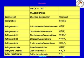
Physical Properties of Tracer Gases Used in Leak Testing
Constituent Content ppm
Partial Pressure
torr Pa(a)
Nitrogen 78.084 493.43 79119
Oxygen 20.946 159.19 21 224
Carbon dioxide 0.033 0.25 33.4
Argon 0.934 7.10 946
Neon 0.0018 18.18 1.38 x 10⁻²
1.84
Helium 0.0005 5.24 3.98 x 10⁻³
0.53
Krypton 1.14 8.66 x 10⁻⁴
0.116
Xenon 0.087 6.61 x 10⁻⁵
0.0088
Hydrogen 0.5 3.80 x 10⁻⁴
0.05
Methane 2.0 1.52 x 10⁻³
0.20
Nitrous oxide 0.5 3.80 x 10⁻⁴
0.05
Table 4: Composition and Partial pressures of dry air at sea level (101.325 kPa)
62.
Website www.sisndt.com orwww.ndtsis.com
MEASUREMENT OF LEAKAGE RATES WITH GASEOUS TRACERS
MODES OF GAS FLOW THROUGH LEAKS
• Different basic laws relate leakage rate to pressure difference across
the leak, the range of absolute pressures involved, and the nature of
the gaseous fluid escaping through the leak. Three basic types of gas
flow that occur in leaks, as discussed earlier are:
• Viscous flow, which typically occurs in probing applications with
gases leaking at atmospheric or higher pressures .
• Molecular flow, which usually occurs in leaks under vacuum testing
conditions.
• Transitional flow, which occurs under test conditions intermediate
between vacuum and pressures higher than atmospheric pressure
63.
Website www.sisndt.com orwww.ndtsis.com
105
104
103
102
101
100
10-1
10-2
10-3
10-4
10-5
MEASUREMENT OF LEAKAGE RATES WITH GASEOUS TRACERS
Types of flow characteristics of tracer gases through leaks as a
function of leak channel radius and gas pressure in pascals.
10-4
10-3
10-2
10-1
100
101
102
103
104
105
R
A
D
I
U
S
OF
T
U
B
E
mm
Viscous
Transition
Molecular
Pressure, Pa (absolute) of for air at 25ºC
64.
Website www.sisndt.com orwww.ndtsis.com
Criteria for Determination of Type of Gas Flow through Leaks
• In flow systems encountered in leak testing with gases, the length of
the mean free path of the gaseous molecules can be used to estimate
the type of flow occurring through leakage paths.
• When determining the nature of flow of gases through leaks, use is
made of two parameters: (1) the mean free path length la, and (2) a
constant d which characterizes the leak opening (diameter or cross-
sectional area).
• The average mean free path length la is determined by using the
average pressure in the leak flow system.
• The criteria that determine the mode of gas flow through leaks, given
in terms of the mean free path length la and the leak dimensional
constant d, are as follows:
– When the ratio la/d is less than 0.01, the gas flow is viscous
– When the ratio la/d is between 0.01 and 1.00, the gas flow is transitional.
– When the ratio la/d is greater than 1.00, the gas flow is molecular. In
molecular flow, the mean free path length is greater than the largest linear
dimension of the cross section of the leak.
65.
Website www.sisndt.com orwww.ndtsis.com
Relation of Viscous Leakage Flow to Pressure Differential Across Leaks
• Viscous flow occurs when the mean free path length of the gas is
significantly smaller than the cross-sectional dimension of a physical
leak. Viscous flow occurs in high-pressure systems such as are
encountered in probing applications where tracer gases are leaking
into air at atmospheric pressures. With viscous flow through leaks,
the flow rate or leakage Q is proportional to the difference in the
squares of the pressures acting across the leak. This relationship is
shown by Poiseuille's law for viscous flow through a cylindrical tube,
in Equations 17 and 18 for the leakage rate, Q:
• Q = (pr4
/8nl)(Pa)(Pl - P2) ( Eqn 17)
• Q = (pr4
/16nl)(p1
2
– p2
2
) ( Eqn 18)
• (where Q is gas flow rate in pascal cubic meters per second; r is
radius of leakage tube in meters; 1 is length of leakage tube in
meters; n is viscosity of leaking gas, Pa-s, P1 is upstream gas
pressure in pascals; P2 is downstream pressure in pascals; Pa is
average pressure within leak path, (P1+ P2)/2, in pascals.
66.
Website www.sisndt.com orwww.ndtsis.com
Relation of Molecular Leakage Flow to Pressure Differential Across Leaks
• Molecular flow occurs when the mean free path length of the gas molecules is
greater than the largest cross-sectional dimension of a physical leak.
• Molecular flow usually occurs through leaks in vacuum systems or systems
which have vacuum applied to the lower pressure side of the pressure
boundary for purposes of leak testing.
• With molecular flow through leaks, the leakage rate Q is proportional to the
difference in pressures applied across the leak.
• This relationship is shown by Knudsen's law for molecular flow through a
cylindrical tube, neglecting the end effect, as shown in Equation 19 for the
leakage rate, Q through a tubular leak with molecular flow:
• Q = 3.342 (r3
/1) (RT/M)1/2
(PI - P2)
• where T is absolute temperature in degrees kelvin; R is gas constant equal to
8.315 . J/mole per kelvin.
• If this value is substituted for R in Equation 19a, the leakage rate in SI units is
given by Equation 19b:
• Q = 9.637 (r3
/1)(T/M)1/2
(pI – P2)
67.
Website www.sisndt.com orwww.ndtsis.com
Relation of Transitional Leakage Flow to Mean Free Path Length of Gas and to Pressure Differential Applied Across Leak Path
.
• Transition flow occurs when the mean free path length of the gas
molecules is approximately equal to the cross-sectional dimension of
the leak. Transitional flow occurs under leakage conditions
intermediate between those for viscous flow and those for molecular
flow. For transitional flow, Knudsen's law (Equation 19) for molecular
leakage is modified by an additional term which depends upon the
ratio R equals 'r/la' of leakage tube radius 'r' to the mean free path
length "la” that applies for the average pressure, (P1 + P2)/2, existing
within the leakage path. This correction term for transitional flow in
leakage paths is given as the factor as FT defined by Equation 20
where Rt =:'r/la'
• FT = 0. 1472Rt + (1 + 2.507Rt)/(1 + 3.095Rt)
• The leakage rate, Q in SI units of Pa-m3/s is given by
• Q = (3.342 r3
/1)(RT/M)1/2
(PI - P2)(FT)
68.
Website www.sisndt.com orwww.ndtsis.com
Gaseous Conductance & Calculation of Conductance Leaks with Various Modes of Flow
• Conductance describes the property of a gas flow system that
permits gas to flow. It is analogous to electrical conductance, the
reciprocal of resistance. The gaseous conductance of a tubular
passageway permits the leakage of a gaseous constituent when a
pressure drop exists between the ends of the tubular hole. The
gaseous conductance is the reciprocal of the resistance of the leak
passageway,
• The gaseous conductance, C = 1/RGas = Q (P1 -P2)
• Gas flow, Q = (P1 -P2) / RGas = (P1 -P2) x C
• The following gives basic relationships required to calculate leak
conductance under various conditions of leak geometry and modes
of gas flow and to estimate variations of leakage rate with different
gas pressures.
• The conductance of a leak exhibiting viscous flow of gas can be
calculated by assuming that the physical leak channel approximates
a straight, cylindrical tube:
69.
Website www.sisndt.com orwww.ndtsis.com
• Viscous conductance of tube, C = (pr4/8nl)Pa
• For calculating the conductance’s of leaks, C is gas conductance in
cubic meters per second; r is radius of bore of tube in meters; 1 is
length of tubular leak passageway in meters; n is viscosity of leaking
gas, .in Pascals;
• PI is upstream pressure in pascals; P2 is downstream pressure in
pascals; Pa is average gas pressure within leak channel, in pascals;
Pa =(P1+P2)/2.
Gaseous Conductance & Calculation of Conductance
Leaks with Various Modes of Flow- Contnd
70.
Website www.sisndt.com orwww.ndtsis.com
Gas Conductance with Two Leaks in Series
• If two different diameter leaks with different conductance values are
connected in series as in Fig. 8, the total conductance of the
connection between extreme ends decreases (resistance increases).
From Equation 23, the conductance of the leak between Sections 1 and
3 may be expressed as
C13 = Q/(P1 – P3) (Eq. 23)
• The total pressure drop across the two leaks in series is given by
P1 – P3 = (P1 – P2) + (P2 – P3) (Eq. 24)
• The pressure drop across each individual leak is shown in
P1 – P2 = Q/C12, P2 – P3 = Q/C23 (Eq. 25)
Atmosphere
Wall 0f system p3
Inside of c12 c23
System P2
Chamber
Inner outer
tracer
Capillary capillary
r
Inlet
P1 wall P2
Atm
P2
Fig.8. Sketch of typical leak paths
connected in series
Fig.9. Sketch of typical leak path
connected in parallel.
71.
Website www.sisndt.com orwww.ndtsis.com
Gas Conductance with Two Leaks in Series
• Now, by combining Equations 23, 24, and 25, the conductance C13 for the two
leaks in series is given by Equation 26:or,
C 13 = Q / (Q/C 12 + Q/C23) (Eq. 26)
• in its reciprocal form:
I/C1-3 = (Q/C12 + Q/C23) / Q = I/C12 + I/C23
• In its general form, Equation 27 may be written as Equation 28:
72.
Website www.sisndt.com orwww.ndtsis.com
Gas Conductance with Two Leaks in Series
• In Equation 28, the subscript T denotes the total conductance of a number of
conductances C1, C2, C3 ... Cn connected in series.
• In the case of only two conductances connected in series, Equation 28 can
be written in the form of Equation 29:
• This case applies for two successive leak conductances connected in series.
This is analogous to the case of two electrical resistors connected in
parallel, or two electrical conductances connected in series.
73.
Website www.sisndt.com orwww.ndtsis.com
Leak Conductance for Two Leak Conductances Connected in
Parallel
• Figure 9 shows the case of two leaks which are connected in parallel. With this
situation, the total leakage through two parallel leaks divides between the two
leakages paths from the high pressure side to the low pressure side of the
pressure boundary. The division of flows depends upon the conductances of the
individual leaks as indicated in Equation 30 below
• Qa = Ca (Pl – P2) = Ca DP 30a)
• Qb = Cb (PI - P2) = Cb DP The total
conductance through the pressure boundary between Points 1 and 2 is given by
Equation 31 :
• C12 = (Ca DP+Cb DP)/ DP
• Simplifying, Equation 31 becomes Equation 32.
• C12= Ca + Cb
• In its general form, the total conductance for n individual leaks connected in
parallel is given by the sum of the individual conductances as in Equation 33: CT
• Cr = Cl+C2+C3+... +Cn
74.
Website www.sisndt.com orwww.ndtsis.com
Conversion of Viscous Flow Rates between Different Gases
• If a flow rate has been identified as viscous for one gas, the viscous
flow for any other gas may be determined using the expression given
in Equation: 34
• Q2 = (nl/n2)Q1 (Eq. 34)
• Where Q1 is flow rate (any units) for gas 1, Q2 is flow rate (same units
as gas 1) for gas 2, nl is viscosity (any units) for gas 1, and n2 is
viscosity (same units as gas 1) for gas 2.
75.
Website www.sisndt.com orwww.ndtsis.com
Conservation of Viscous Conductance
between Different Gases
• Dividing both sides of Equation 34 by the pressure drop will give
conductance C rather than flow Q. Any two conductance’s, C1 and C2, will
then have a relationship given in Equation: 35
• C2 = (n2 /nt)C1 (Eq. 35)
• Where C1 is conductance (any units) for gas 1, C2 is conductance (same
unit) for gas 2.
• A few comparisons that may be used for converting either conductance or
flow from Helium flow rates for other gases are
76.
Website www.sisndt.com orwww.ndtsis.com
Conservation of Viscous Conductance
between Different Gases
To Convert to Multiply Helium Flow by
Q of argon 0.883
Q of neon 0.626
Q of hydrogen 2.23
Q of nitrogen 1.12
Q of air 1.08
Q of water vapor 2.09
77.
Website www.sisndt.com orwww.ndtsis.com
Comparison of viscous flow rates of other gases with Helium flow rates
• Conversion of Molecular Flow Rates between Different
Gases
• If molecular flow occurs, the flow rate for one gas may be compared
to the flow rate for any other gas by Equation: 36
• Q2 = (M1/M2)1/2
Q1
• Where Q1 is flow (any units) for gas 1, Q2 is flow (same units as gas
1) for gas 2, M1 is molecular weight for gas 1, and M2 is molecular
weight for gas 2.
• 3.3.9.3 Conversion of Flow Rates for Molecular Conductance
• The conductance under conditions of molecular flow for one gas may
be compared to the conductance for another by using the expression
of Equation : 37
• C2 = (MI/M2)1/2
C1
78.
Website www.sisndt.com orwww.ndtsis.com
• A few comparisons that may be used for converting either
conductance or flow are given in
To Convert to Multiply Helium Flow by
Q of argon 0.316
Q of neon 0.447
Q of hydrogen 1.41
Q of nitrogen 0.374
Q of air 0.374
Q of water vapor 0.469
Comparison of molecular flow rates of other gases with Helium
flow rates.
Comparison of viscous flow rates of other gases with Helium flow
rates
79.
Website www.sisndt.com orwww.ndtsis.com
Effect of Temperature on Gas Conductance with
Molecular Flow
• The Effect of temperature on conductance when the flow is molecular
should not be overlooked.
• The conductance changes in direct proportion with the square root of
gas temperature.
• The expression of Equation 38 is for a variation in gas conductance
resulting from a change in temperature only, with pressure and
dimension remaining constant
• C2 = (T2/T1)1/2
x C1
80.
Website www.sisndt.com orwww.ndtsis.com
Mechanics of Mass Transfer in Gas Flow
• Mass transfer attributed to leakage can occur in two modes:
pneumatic flow and permeation.
• Pneumatic flow occurs when leakage is by passage of fluid through
finite holes.
• Permeation is passage of a fluid into, and out of a solid barrier having
no holes large enough to permit more than a small fraction of the
molecules to pass through any hole.
81.
Website www.sisndt.com orwww.ndtsis.com
Leakage Rates for Different Modes of Pneumatic Flow of Gas in Leaks
• Pneumatic gas flow in leaks may be placed in five categories: laminar,
molecular, transition and choked leakage flow's. The approximate
ranges of flow rates for various pneumatic modes of gas flow are
• Turbulent flow occurs with leakage rates above 10-3
Pa-m3/s.
• Laminar flow occurs with leakage rates in the range from 10-2
to 10-1
Pa-m3/s.
• Molecular flow is most probable with leakage below 10-6
Pa-m3/s.
• Transition flow occurs in the gradual transition from laminar to
molecular flow.
• Choked flow occurs when the flow velocity approximates the speed
of sound in the gas
• Laminar flow is the predominant mode of leakage flow in the range of
leakage rates of interest in most leak testing.
82.
Website www.sisndt.com orwww.ndtsis.com
CHAPTER 3
CHARACTERISTICS OF GASEOUS TRACERS USED IN
LEAK TESTING – QUESTIONAIRE
Q1) Charles Law states
A. Vf / Vi = Ti / Tf
B. Vf / Ti = Vi / Tf
C. Vi x Ti = Vf x Tf
D. Vi x Tf = Vf x Ti
Where V and T are the initial and final volume and temperature
Q2) At Charles Law temperature is expressed in
E. Degree centigrade
F. Degree farenheit
G. Degree Rankin
H. None of the above
83.
Website www.sisndt.com orwww.ndtsis.com
LEAK TESTING – QUESTIONAIRE
Q3) Boyles Law states
A. Pi / Vi = Pf / Vf at 0°F
B. Vi / PI = Vf / Pf at 0ºC
C. Pi / Pf = Vf / Vi at constant temperature
D. Pi x Vf = Pf x Vi at constant temperature
Q4) 1 M3
of gaseous Helium at 0ºC and 1 M3
of Gaseous Helium at 32°F
E. will occupy same volume
F. will occupy different volume
G. As long as the pressure is the same it will occupy same volume
H. None of the above
Q5) Volume of the gas can be specified
I. By the volume in cc it occupies in space alone
J. By the volume in M3
it occupies in space alone
K. Volume occupied in space at particular pressure
L. Volume occupied in space at particular pressure and temperature
84.
Website www.sisndt.com orwww.ndtsis.com
LEAK TESTING – QUESTIONAIRE
Q6) Number molecules in On mole of N2 is
A. 14
B. 7
C. 6 x 10²³
D. none of the above
Q7) Two moles of N2 gas molecules will occupy
E. 1 liter
F. 14 liter
G. 44.8 liter
H. 22.4 liter
Q8) At No of O2 is 16 and At no of Carbon is 12 and if one mole of O2
occupies 22.4 liters then one mole of carbon will occupy
I. 1 liter
J. 16.5 liter
K. 22.4 liter
L. none of the above
85.
Website www.sisndt.com orwww.ndtsis.com
LEAK TESTING – QUESTIONAIRE
Q9) The ideal gases are the gases that obey
A. P V = R / T
B. P V = m R T
C. P V = R T
D. P V = P1 V1
Q10) Real Gases variates from ideal gases
E. At normal densities
F. At very high density
G. At very low pressure
H. Very high pressure
Q11) Tracer gas should have
I. Low diffusion rate
J. Very Low diffusion rate
K. High diffusion rate
L. None of the above
86.
Website www.sisndt.com orwww.ndtsis.com
LEAK TESTING – QUESTIONAIRE
Q12) Which primarily causes the molecular motion
A. Heat
B. Pressure
C. Concentration
D. Volume change
Q13) Kinetic theory of gases is applicable to
E. Ideal gases
F. Real gases
G. Actual gases
H. None of the above
Q14) The actual volume of the gas molecules
I. Equal to the volume of the space occupied by the gas
J. More than the volume of the gas occupied if the temperature is more
K. Negligible while compared to the volume occupied by the gas
L. None of the above
87.
Website www.sisndt.com orwww.ndtsis.com
LEAK TESTING – QUESTIONAIRE
Q15) What is the partial pressure of argon gas if it is present in the
atmosphere at 0.9 %
A. 2 K Pa
B. 0.91 K Pa
C. 79.03 K Pa
D. 101.3 K Pa
Q16) The ratio of the mean free paths of two gases are given
E. λ 1 / λ 2 = (η 1 / η 2) M1 / M2
F. λ 1 / λ 2 = (η 1 / η 2) M2 / M1
G. λ 1 / λ 2 = (η 2 / η 1) M / M2
H. λ 2 / λ 1 = (η 1 / η 2) M2 / M1
Q17) If η1 , η2 , η3 are the viscosities and C1 , C2 ,C3 are the
concentration and P1 , P2 , P3 are the Partial pressures then
I. N Mixture = η1c1 + η2 c2 + η3 c3
J. N = η1 c1/p1 + η2 c2/p2
K. N = η1 + η2 + η3
L. 1/N = 1/η1 + 1/η2 +1/η3
88.
Website www.sisndt.com orwww.ndtsis.com
LEAK TESTING – QUESTIONAIRE
Q18) Molecular flow occurs when the mean free path is
A. Less than the cross section of the leak
B. Equal to the cross section of the leak
C. More than the cross section of the leak
D. None of the above
Q19) In Laminar flow, flow- rate is directly Proportional
E. to the pressure difference
F. Squire of the pressure difference
G. Leakage gas viscosity
H. All of the above
I. None of the above
Q20) In viscous flow, the rate of flow of gas Q 1 / Q 2 is equal
J. η1 / η2
K. η2 / η1
L. M1 / M2
M. M2 / M1
89.
Website www.sisndt.com orwww.ndtsis.com
LEAK TESTING – QUESTIONAIRE
Q21) In molecular Flow, Flow rate Q 1 / Q 2 is equal to
A. M2 / M1
B. M2 / M1
C. η1 / η2
D. η1 / η2
90.
Website www.sisndt.com orwww.ndtsis.com
CHAPTER – 4
VACUUM TECHNOLOGY
• At normal atmospheric pressure, gas molecules make many collisions
with each other.
• The average distance that a molecule travels before colliding with
another molecule is known as the mean free path (MFP).
• The mean free path of two different gases at the same pressure will not
be the same; this is because the MFP depends on the molecular size,
which varies from one gas to another. In spite of this fact, it is still
possible to give a useful relationship between MFP and pressure.
• The approximate values of mean free paths for air and other gases are
given as a function of gas pressure
• Mean free path, MFP = 0.0095/P
where MFP is mean free path with length in meters, and P is gas
pressure in pascals absolute.
91.
Website www.sisndt.com orwww.ndtsis.com
Gas Quantity and Pumping Speed
• From the gas laws, it is known that the product PV of pressure P and volume
V is proportional to the number of molecules in a sample of gas.
• In static systems, the PV product is constant at a given temperature.
• This product PV is known as the quantity of gas expressed in Pascal cubic
meters (Pa.m3
) or atmospheric cubic centimeters.
• In steady flow, the same quantity of gas (number of molecules) that enters
one end of a tube must leave at the other end, even though there may be
different volumes of gas entering and leaving per unit time.
• If the PV product is used as a measure of the amount of gas flowing through
a tube, computation may be done with a minimum of complication.
• The volumetric pumping speed S is the time rate of volume displacement,
• Volumetric pumping speed, S = V/t
• The unit of pumping speed S would be cubic meters per second (m3
/s).
92.
Website www.sisndt.com orwww.ndtsis.com
Throughput and leakage Rate
• In vacuum practice, the preferred description of the rate of flow of gas is
commonly called "throughput". Throughput is the quantity of gas, or a
measure of the total number of molecules at a specified temperature, passing
an open section of the vacuum system per unit time. Leakage rate is a similar
measure of the total number of molecules at a specified temperature passing
through a leak per unit time. Q is the symbol used for throughput of gas in
unit time.
• Gas throughput, Q = PV/t (Pa.m3
/s) (Eq. 3)
• By combining Equations 2 and 3, the product of pumping speed S and gas
pressure P can be equated to throughput by Equation 4:
Gas throughput, Q = S x P (Pa.m3
/s)
93.
Website www.sisndt.com orwww.ndtsis.com
• Equation in the last slide is the universal relationship upon which
vacuum pumping throughput calculations are based. As an example
of its use, suppose the gas in the pipe between Sections 1 and 2
passes Section 1 in 1s, and this volume (V) is 0.1 m3 and the-pressure
(P) at Section 1 is 10-4
Pa. The throughput, Q, is the product of
pressure P = 10-4
Pa and displaced volume V= 0.1m3
divided by the
time, t = 1s, or:
• Q = S X P =PV/t = 10-4
x 0.1=10-5 Pa.m3
/s
Throughput and leakage Rate
94.
Website www.sisndt.com orwww.ndtsis.com
Gas Conductance
• In vacuum, importance is not of the resistance a tube or component
offers to gas flow, but instead uses the reciprocal term
"conductance." Conductance is a measure of the ability of a vacuum
component to permit gas flow or not to impede it. Consequently, the
greater the resistance, the smaller the conductance and vice versa. In
a vacuum circuit, the pressure differential across a pipe is the
product of throughput (gas flow) Q and resistance R. Refer Fig. 2.
Equation 5 states this relation mathematically:
• Pressure differential, DP = (P1 –P2) = Q x R = Q/C
• Since R is equal to I/C, Equation 5 may be written in the form of
Equation 6:
• Gas conductance, C = Q/DP = Q/(P1 –P2)
• Equation 6 is the defining equation for gas conductance: the ratio of
throughput Q to pressure differential, DP, across the conductance.
95.
Website www.sisndt.com orwww.ndtsis.com
Gas Conductance with Sequential Tubes or Passages
• If two different diameter pipes with different conductance values are
connected in series as in the total conductance of the connection
between extreme ends decreases (resistance increases).
• Cl3 = Q/(P1 -P3)
• Now, P1 -P3 = (P1 – P2) + (P2 - P3)
• and P1 –P2 = Q/C12 and P2 -P3 = Q/C23
96.
Website www.sisndt.com orwww.ndtsis.com
• If tubes are connected in series the total conductance CT is given as
CT = 1 /( C1 +C2 + C3 --- C n ) where C1 , C2 , C3 are the Individual
conductance connected in series
Gas Conductance with Sequential Tubes or Passages
97.
Website www.sisndt.com orwww.ndtsis.com
Similarly if the tubes are connected in parallel then the Total
conductance is given as
CT = C1 + C2 + C3 -- +C n
TO P1
DIFFUSION PUMP
P2
Qa Pipe a
Pipe b
Qb
Gas Conductance for Pipes or Tubes Connected in
Parallel
98.
Website www.sisndt.com orwww.ndtsis.com
Pumping Speed
• In operating a vacuum system, the rate .of removal of gases is
measured by pumping speed, S. From Equation 4, pumping speed is
defined as the ratio of the throughput, Q, to the pressure, P, at the
point in the system.
Pumping speed, S = Q/P (m3
/s}
• If the inlet to a vacuum pump were connected directly to a vacuum
vessel, then the pumping speed at the vessel would be the same as
that at the pump inlet.
• Since it is physically impossible to join the pump and vessel without
introducing a connector, the pumping speed at the vessel will be
lower than that at the pump.
• Pumping speed loss depends on the magnitude of the conductance,
which causes a loss in pressure, or creates differential pressure
between pumps and vessel.
99.
Website www.sisndt.com orwww.ndtsis.com
• The flow of gas is from the chamber to the pump.
• DP = Pc – Pp = Q/C
• In Equation the subscripts c and p refer to the chamber and pump,
respectively. The throughput Q is the product of the speed, S, and
pressure, P, where each is measured at the same point, such as at the
pump or, alternatively, at the chamber.
Pumping Speed
100.
Website www.sisndt.com orwww.ndtsis.com
NET Pumping Speed
• Net pumping speed relationship applicable to conductance C
between vacuum pump and chamber being evacuated. Pressure at
vacuum chamber is Pc and pumping speed Sc = Q/Pc. Pressure at
Vacuum pump is Pp and pumping speed is Sp = Q/Pp
Q
DIFFUSION
PUMP
Sn / Pn = Qn
S p= Q/ P p
Qc = Sc / Pc
VACUUM
CHAMBER
Sc== Q /Pc
101.
Website www.sisndt.com orwww.ndtsis.com
• Therefore, at the pump:
• Throughput, Qp = SpPp and Pressure, P p = Q/Sp
• and at the chamber being evacuated:
• Throughput, Qc = ScPc and Pressure, Pc = Q/Sc
• So (Q/Sc -Q/Sp) = Q/C
• Rearranging terms: Q/Sc = Q/Sp + Q/C
• and multiplying by l/Q: 1/Sc = 1/Sp + l/C
• In the general case, the net speed, Sn. at any point in a vacuum
system is related to the speed of the pump, Sp, and the total
conductance, I/Sn = 1/Sp + l/Ct
NET Pumping Speed
102.
Website www.sisndt.com orwww.ndtsis.com
VACUUM PUMPS AND SYSTEMS
• Introduction to Vacuum Pumping
• In order to attain vacuum pressure in a container, some means of
pumping must be employed. The ultimate pressure which can be
achieved by the vacuum pump will be determined by conditions such
as:
– The leak tightness of the vacuum system
– The nature and condition of materials within the vacuum system that
might cause out gassing
– The operating characteristics of the pumps in combination with the
specific vacuum system.
103.
Website www.sisndt.com orwww.ndtsis.com
Operation of Mechanical Pumps
• The mechanical pump is an essential component used in vacuum systems to
pump a chamber from atmospheric pressure down to about 0.1 Pa (10-3 torr)
vacuum pressure.
• Of the various types of mechanical pumps, the rotary oil-sealed vacuum
pump shown below is most common.
Oil
ROTOR
VANE
SPRING
OUTLET INLET
104.
Website www.sisndt.com orwww.ndtsis.com
Operation of Mechanical Pumps-Contnd
• The pump consists of a stationary housing, an eccentrically mounted rotor
with two spring-loaded vanes, an inlet port, and a discharge port.
• Air enters the pump from the vacuum chamber through the inlet port.
• This air is trapped, compressed, and ejected into the atmosphere through the
discharge port by means of the rotor arrangement. Sealing of the eccentric
rotor vacuum pump is done by an oil film between the two sliding spring-
loaded vanes that make contact between the rotor and the housing.
• Oil is used as the pump sealant.
• Close tolerances must be maintained to prevent leaks and by-passing of
gases.
• Consequently, care must be taken to prevent solid particles from entering the
pump.
• Each rotation of the rotor discharges two volumes; each volume is a certain
percentage of the volume to be evacuated.
105.
Website www.sisndt.com orwww.ndtsis.com
Pump Oil Used in Rotary Vacuum Pumps
• The operating fluid in any type of pump is called the pump fluid or
pump oil.
• With rotary pumps, normally good quality light petroleum oil, with the
high vapour pressure fractions removed, is used to provide pump
sealing and lubrication between the rotor vanes and stator housing.
• The oil for lubricating and sealing is contained in an oil reservoir.
• The arrangement of the reservoir differs from manufacturer to
manufacturer.
• In some small pumps, the pump chamber is actually immersed in the
reservoir, while for the larger pumps the reservoir is usually
separated from the pump chamber, often being mounted above the
pump itself.
106.
Website www.sisndt.com orwww.ndtsis.com
Prevention of Condensate Contamination of Pump Oils
• Contamination of pump oil is one of the main difficulties with rotary pumps.
As the gases and vapors are compressed, the vapors will tend to condense
and contaminate the oil.
• Degassing of vapours from pump oil can limit the ultimate vacuum pressure
attainable.
• Pumps are available with a gas ballast valve incorporated, which minimises
the condensation of vapours in the pump oil.
• The gas ballast valve is a small valve that can be opened manually to admit a
controlled amount of air to the pump cylinder during part of the compression
cycle. This will dilute the vapours to the point where they do not condense
during compression.
• The violent agitation of the oil by the additional air rushing through the pump
causes re-evaporation and exhaust of water which may have been pumped
from the vacuum system in vapour form and condensed in the pump oil.
• In normal high vacuum service, the ballast valve is usually kept closed since
there is usually very little water vapour present. The minimum pressure
obtainable is also slightly higher with the ballast valve open.
107.
Website www.sisndt.com orwww.ndtsis.com
Ultimate Pressure Attainable in Rotary Pump
• The limiting pressure after sufficient pumping time that further
reductions in pressure will be negligible, is called the ultimate
pressure. The range of ultimate pressures of commercial rotary
vacuum pumps extends from about 3 mPa to I kPa (2 x 10⁻⁵
to 5 torr).
The low pressure of 3 mPa is reached only under the most ideal
conditions. The ultimate pressure will be determined by:
– Out-gassing of the pump
– The seal between rotor and stator
– Contamination of pump oil
– The vapour pressure of the oil used.
108.
Website www.sisndt.com orwww.ndtsis.com
Mechanical pump speed as a function of gas pressure for a pump rated
at 400 L/min at atmospheric pressure
Ultimate Pressure Attainable in Rotary Pump
10 -3
10 -2
10 -1
10 0
10 +1
10 +2
10 +3
10 +4
400
300
200
100
50
0
PRESSURE Pa
109.
Website www.sisndt.com orwww.ndtsis.com
Pumping Speeds of Rotary Mechanical Vacuum Pumps
• Apart from the ultimate pressure that can be achieved by any
particular pump, there is an interest in how fast the pump can reduce
the pressure in a vacuum system to the operating level.
• Manufacturers normally specify the pumping speeds of their
mechanical pumps at atmospheric pressure.
• In general, rotary pumps start pumping at atmospheric pressure and,
as the pressure is reduced, the pump becomes less efficient:
• It is then pumping the same volume, but at lower pressure.
Eventually, the pumping speed becomes zero at the ultimate
minimum pressure.
110.
Website www.sisndt.com orwww.ndtsis.com
• A plot of pressure as a function of pumping speed for a 400 L/min (15
cfm) mechanical pump.
• It is seen that at atmospheric pressure, the pump is rated at 400
L/min;
• at 0.1 Pa, the pumping speed is 200 L/min; at 0.01 Pa, the pumping
speed is 100 L/min.
• The pumping speed reduces to zero at 10-3
Pa, which is the ultimate
pressure attained by this pump.
• At this point the gas-handling capacity has been saturated by the gas
load from the pump, thereby reducing its effective pumping speed to
zero.
Pumping Speeds of Rotary Mechanical Vacuum
Pumps
111.
Website www.sisndt.com orwww.ndtsis.com
Operation of Vapour or Diffusion Pumps
• Although mechanical rotary pumps sometimes attain pressures
below 0.1 Pa (10-3
torr), they are generally used in the 100 to 0.1 Pa
range.
• To obtain pressures well below 0.1 Pa, the vapour pump is most
commonly used.
• The principle of operation of vapour pumps is entirely different from
that of a rotary oil-sealed pump.
• The vapour pump, or diffusion pump, operates in the molecular flow
region.
• This operating principle of the three-stage fractionating diffusion
pump
112.
Website www.sisndt.com orwww.ndtsis.com
• The electric heater at the bottom of the pump heats the pump oil until
it boils and gives off oil vapour (molecules of oil in the gaseous
state).
• These molecules of oil then rise up the jet stack and are forced
through the nozzles to form a high velocity vapour stream,
• which is directed downward and downward toward the wall of the
pump.
• Molecules of gas that diffuse from the vacuum region toward the jet
stream are struck by oil vapour molecules and accelerated downward
toward the discharge port which leads to the fore pump.
Operation of Vapour or Diffusion Pumps
113.
Website www.sisndt.com orwww.ndtsis.com
• Construction of three-stage diffusion type vacuum pump
GAS
MOLECULES
CONDENSED
OIL
COOLING WATER
JACKET
EXHAUST GAS TO
FORE PUMP
FORE LINE
BOILING LIQUID OIL
HEATER
NOZZLE
GAS INLET FROM VACUUM CHAMBER
Operation of Vapour or Diffusion Pumps
114.
Website www.sisndt.com orwww.ndtsis.com
• After performing its function, the oil vapour condenses on the inner
pump wall surface which is cooled to a temperature below the
condensation point of the oil by water flowing in an outer jacket.
• The condensed oil then runs back down into the boiler while the gas
molecules are directed to successively lower stages.
• The gas thus directed toward the bottom of the pump is further
pumped by oil vapour jets directed from the lower nozzles.
• It is then pumped through the fore-line by a mechanical pump called a
fore pump.
• After the oil drops to the bottom of the pump, it is re-boiled and the
cycle repeats.
Operation of Vapour or Diffusion Pumps
115.
Website www.sisndt.com orwww.ndtsis.com
Vacuum Pressure Limitations of Vapour Diffusion Pumps
• A diffusion pump cannot operate at pressures above 0.1 Pa (10-3
torr)
because the oil vapour jets cannot form in the viscous flow region.
• Therefore, the pump must start pumping in a chamber that is already
under vacuum (such as that attained with a rotary mechanical fore
pump).
• Oil is the most frequently used diffusion pump fluid because of its
low vapour pressure at room temperature.
• The lowest attainable pressure of the diffusion pump is determined in
part by the vapour pressure of the oil and the temperature of the
available cooling water.
• Silicone oils specified by pump manufacturers have vapour
pressures, under these conditions, of about 0.1µPa (10-9
torr).
• The popularity of the diffusion pump is due to its wide range of
operation, low cost, reliability, and lack of moving parts.
• The pump heaters are usually mounted from the outside and can be
replaced during operation.
116.
Website www.sisndt.com orwww.ndtsis.com
Operation of Baffles and Traps
• One of the objections to diffusion pumps has been the possibility of
contaminating the vacuum chamber work area with the pump fluid.
• By providing suitable traps and baffles between the pump and the
vacuum chamber, back diffusion of oil and oil vapour can be
minimised and condensable vapours from the chamber may be
trapped.
• As a general rule, the pumping speed of the system goes down as the
trapping efficiency of baffles and traps goes up, due to decreased
conductance.
• The baffle or trap should be kept as cold as possible.
• However the temperature of surfaces of the first baffling stage above
a pump should be cool enough to condense the oil vapours, but not
so cold as to freeze the pump oil and-prevent it from flowing back into
the pump
117.
Website www.sisndt.com orwww.ndtsis.com
Operation of Cold Traps
• A cold trap ensures that those few oil molecules that may get by the
baffle will not get to the vacuum chamber.
• A cold trap, therefore, stops back migration of pump-oil vapours.
• It is also very effective as a cryogenic pump for pumping
condensable vapours such as water vapour, grease vapours, mercury
vapour, and other undesired contaminants.
• As a cryogenic pump, the cold trap reduces system pressure by
taking molecules out of the gas or vapour phase and trapping them
on its surface.
• These molecules are not pumped out of the vacuum system and
discharged to atmosphere.
• The most common methods used to obtain low temperatures for cold
traps are mechanical refrigeration, dry ice, and liquid nitrogen.
118.
Website www.sisndt.com orwww.ndtsis.com
• (a) Combination Baffle and Trap With Optically Dense Chevrons
• (b ) Thimble Trap .
Cold traps used in vacuum pumping systems to condense vapour
molecules.
LN2
H 2O
(a)
TO
CHAMBER
TO DIFFUSION PUMP
Operation of Cold Traps
(b)
119.
Website www.sisndt.com orwww.ndtsis.com
Schematic diagram of a typical complete vacuum system
Operation of Cold Traps
Pumping port
Vent valve
High vacuum valve
(No.1)
Diffusion pump
MECHANICAL PUMP
LEAK TEST
PORT
ACCESS VALVE TO VACCAM
CHAMBER
ROUGHINGVALVE 2
COLD TRAP
ROUGHINGVALVE 3
BAFFEL
BALL JAR CHAMBER OR OTHER PROCESS VESSEL
To
atmoshphere
120.
Website www.sisndt.com orwww.ndtsis.com
Turbo molecular Vacuum Pumps
• The turbo molecular pump serves as an alternative to the diffusion
pump, and must also be backed by a fore pump.
• Its principle advantage over the diffusion pump is that it provides an
essentially vapour free vacuum without the use of baffles or cold
traps.
• Thus, for a system where the back-streaming of vapour from a
diffusion pump is undesirable or intolerable, a molecular pump could
be used.
• Its main disadvantage is that it has high speed rotating parts whereas
the diffusion pump has no moving parts.
• It also requires air gap tolerances of the order of 2 to 5 μ.m between
the high speed rotor and grooves in the stator.
• A molecular pump cannot operate at pressures above 13 to 1.3 Pa
(10-1
to 10-2
mm Hg), and it must be backed by a mechanical fore
pump.
121.
Website www.sisndt.com orwww.ndtsis.com
• A turbo molecular pump is a mechanical vacuum pump which creates
a gas flow toward a suitable fore pump by imparting momentum or
motion to gas molecules by means of a rapidly rotating rotor with
successive rings with inclined blades.
• These blades rotate with circumferential speeds comparable to the
thermal motion of the molecules (speeds of 100 to 700 m/s) .
• Some molecules are struck by the rotor blades and rebound in a
favourable axial direction toward the stator blades.
• The molecules rebound from these stator blades in a direction
favourable for their being impelled by the next stage stator blades,
and so on-as the process is repeated through all successive stages
of rotor and stator blades.
• The series of impacts statistically favour motion through the turbine
stages toward the discharge port and constitute a pumping action
with a very high compression ratio.
Turbo molecular Vacuum Pumps
122.
Website www.sisndt.com orwww.ndtsis.com
• As the gas is compressed while passing through successive stages
of the turbine, it is necessary to decrease the dimensions of the air
passages so as to keep them comparable with the mean free path of
the molecules.
• The system must already be evacuated by a fore pump before a
molecular pump can start pumping.
• A turbomolecular pump can achieve pressures down to 10-6
to 10-7
Pa
(10-8
to 10-9
mm Hg). Pumping speeds for air vary from about 140 to
3500 L/s, depending upon the size of turbo molecular pump selected.
Turbo molecular Vacuum Pumps
123.
Website www.sisndt.com orwww.ndtsis.com
Comparison of Vacuum Pumps
• Different types of vacuum pumps available and are used for production of
different levels of vacuum in the system and their capability are given below: A
comparison of different pumps
Pump Capability
1. Rotary vacuum pump From Atm 1.33 Pa (10-2
Torr)
2. Root (lobe) Pump From 13 pa. to 133 mPa (10-3
torr )
3. Diffusion Pump From 13.3 Pa to 1 x 10 -7
Pa. (10-9
Torr)
4. Turbo-molecular Pump & From 1.33 Pa to 1 x 1O-7
pa. (10-9
Torr)
Molecular Drag Pump
5. Getter Ion & Cryogenic
Pump
From 13.3 mPa. to 1 x 10 -8
Pa. (10-14
Torr.)
124.
Website www.sisndt.com orwww.ndtsis.com
Pressure (Pa)
Fig 10. Comparison of Vacuum pumps
Comparison of Vacuum Pumps
GETTER ION AND & CRYO
TURBOMOLECULAR AND /MOLECULAR DRAG
DIFFUSION
ROOTS
ROTARY
P
U
M
P
S
Atm 100 1Pa 10 – 2
10 – 4
10 – 6
10 – 8
10 – 10
101 K.Pa
125.
Website www.sisndt.com orwww.ndtsis.com
CHAPTER 4
VACUUM TECHNOLOGY – QUESTIONAIRE
Q1) Bafflers and traps are used
A. To minimize and avoid the contamination of oil vapor
B. To recirculate oil vapor effectively into the system
C. To freeze out the pump oil so that it does not flow back into the pump
D. All of the above
Q2) The efficiency of the bafflers and cold traps goes up
E. The conductance goes up
F. Pumping speed of the system goes down
G. Both of the above
H. None of the above
126.
Website www.sisndt.com orwww.ndtsis.com
VACUUM TECHNOLOGY – QUESTIONAIRE
Q3) TMB uses
A. Bafflers and cold traps
B. It has no moving parts
C. It need not be backed by the fore pump as it is highly efficient
D. All of the above
E. None of the above
Q4) The Vapor pump operates on the principle of
F. Rotatory pump
G. Displacement pump
H. Diffusion pump
I. All of the above
J. None of the above
127.
Website www.sisndt.com orwww.ndtsis.com
VACUUM TECHNOLOGY – QUESTIONAIRE
Q5) Mechanical pump
A. Rotatory pump
B. Displacement pump
C. Both of the above
D. None of the above
Q6) Diffusion pump cannot operate above 0.1 Pa because
E. Oil vapor jets cannot get formed in the viscous floe region because of
high vapor pressure
F. Oil becomes thick and gets struck at high pressure like 0.1 Pa
G. Oil vapor cannot get formed because oil has low vapor pressure at room
temperature
H. All of the above
I. None of the above
128.
Website www.sisndt.com orwww.ndtsis.com
CHAPTER 5
PRESSURE CHANGE TECHNIQUES
INTRODUCTION TO PRESSURE INSTRUMENTATION AND MEASUREMENTS
• Barometric or atmospheric pressure is the ambient pressure caused by
the weight of the earth's atmosphere. Since the weight of the overlying
earth's atmosphere decreases with an increase in altitude, barometric
pressure decreases at higher elevations above sea level.
• Standard barometric pressure at sea level is taken as equal to 101.325
kPa. This pressure is equivalent to an absolute pressure of 14.696 psia. It
is also equal to the pressure exerted by a mercury column whose length
is equal to 760 mm (760 torr).
• Gauge pressure is the pressure above (or below if measured from gauge
zero) atmospheric pressure, at the location of measurement. This
pressure can be measured with an ordinary pressure gauge or with a
manometer, or with other types of instruments. Gauge pressure is
measured in kilo-pascals gauge (kPa gauge), pounds per square inch
gauge (psig), or in terms of heights of water or mercury columns in open-
end manometers (inches of water, millimeters of mercury, etc.).
129.
Website www.sisndt.com orwww.ndtsis.com
INTRODUCTION TO PRESSURE
INSTRUMENTATION AND MEASUREMENTS
• Absolute pressure is the pressure above the absolute zero value
corresponding to empty space. It is equal to the sum of the local
atmospheric pressure and the gauge pressure. The absolute pressure
within an enclosure can be measured directly with a well-type
absolute manometer or an absolute pressure gauge, thus eliminating
the need for a barometer. The word "absolute" is normally shown on
the face of an absolute pressure dial gauge or other absolute
pressure measuring instrument. Absolute pressure is preferably
measured in SI units of pascals.
• Barometer is an absolute pressure gauge used to measure the
atmospheric pressure at a specific location. When used for the
purpose of indicating elevation above a reference level (such as sea
level or the earth's surface), it may be identified as an altimeter.
Barometric pressure may be measured in kilopascals ,pounds per
square inch, or by heights of a mercury column (millimeters or
inches), or in millibars (thousandths of a standard atmospheric
pressure).
130.
Website www.sisndt.com orwww.ndtsis.com
INTRODUCTION TO PRESSURE INSTRUMENTATION AND MEASUREMENTS
• Water vapour pressure is the pressure exerted by water vapour (typically
within a test system), and constitutes a partial pressure contributing to
the total pressure within an enclosure. Water vapour pressure is usually
expressed in Pascals, kilopascals, pounds per square inch. This
pressure is usually determined from a set of steam tables by using the
dew point temperature as the entry point.
• Quartz manometer is a high-accuracy pressure measuring instrument
containing a helical Bourdon spring formed of quartz, often used for
measuring differential pressures. It should be maintained at constant
temperature for high accuracy and repeatability of angular deflection as a
function of differential pressure.
• Manometer is an instrument, usually a U-shaped tube containing water or
mercury, for measuring pressure (or pressure differentials) of gases and
vapours. The difference in liquid column height in the two vertical arms of
the U-tube indicates the pressure difference. Units of inches of water or
millimeters of mercury may be read from scales on the manometer
assembly.
131.
Website www.sisndt.com orwww.ndtsis.com
Glossary of Terms Related to Temperature and Temperature Measurements
• The need for measuring ambient (dry bulb) temperature and dewpoint
temperature during pressure change tests requires an understanding
of the following terms:
• Ambient or atmospheric temperature is the temperature of the
atmosphere surrounding the rest location, and is commonly
expressed in degrees Celsius (°C) or degrees Fahrenheit (°F).
• Absolute temperature is the temperature measured from absolute
zero temperature, expressed in Kelvins (K) in the SI system of Units.
Absolute zero temperature corresponds to zero kelvins 1.0 K), and is
equal to –273.15 °C (-496.7ºF). Absolute kelvin temperatures can be
derived from temperatures in other units by Equation s 1, 2 or 4:
132.
Website www.sisndt.com orwww.ndtsis.com
• K = 273.15 + °C (or rounded. 273 + °c) (Eq. 1)
• and from Fahrenheit temperatures by Equation 2
• K = (459.7 + °F)/1.8 [or rounded (460 + °F)/1.8] (Eq. 2)
• Absolute temperatures in degrees Rankine (ºR) are derived from
temperatures in Fahrenheit degrees by Equation 3:
• °R= 459.67 + °F (or rounded, 460 + °F) (Eq. 3)
• Finally, absolute temperatures in degrees kelvin can be determined
from Rankine temperature values by Equation 4:
• K = °R/1.8 (Eq. 4)
Glossary of Terms Related to Temperature
and Temperature Measurements
133.
Website www.sisndt.com orwww.ndtsis.com
• Average absolute internal temperature is a measure of the absolute
temperature within a closed (test) system, and is expressed in
kelvins. For small systems, it is usual practice to assume that this
internal gas temperature is equal to the average wall surface
temperature. Average internal temperature is typically abbreviated as
IAT or more simply as T in many of the equations.
• Dewpoint temperature (DPT) is that temperature at which the gas in a
system would be capable of holding no more water vapour, and
condensation in the form of dew would occur.
• Weighted temperature for both internal temperature and for dew point
temperature is determined by multiplying the average temperature for
each section of the test system by a fraction based upon the
proportion of the total system volume contained in that section. The
resulting values for each section of the system are then totaled to
arrive at the final weighted average values.
Glossary of Terms Related to Temperature and Temperature
Measurements
134.
Website www.sisndt.com orwww.ndtsis.com
• An electrical resistance temperature detector (RTD) is used for measuring
internal air temperature (dry bulb) in pressurized systems. It consists of a
metal tube containing a metallic core with winding of wire whose
resistance varies with temperature. This sensing coil connected by a three
conductor electrical lead wire system through a signal-conditioning
system to a temperature readout instrument.
• A thermocouple is a bimetallic junction which produces an output
electromotive force (emf) that varies with its temperature. The mille volt
readout of the thermocouple junction is measured by means of a
potentiometer and used to determine a temperature reading. The most
accurate, economical type of thermocouple for use in the ambient
temperature range is the copper to copper-constantan junction
thermocouple. The thermocouple is less desirable than resistance
temperature measuring devices from a stability and accuracy standpoint.
• A dewpoint sensor is an electrical device for measuring dewpoint
temperature in a pressurised system. It works on the principle of
balancing the moisture content in the element with moisture content of the
surrounding atmosphere. The dew- point sensor is connected by electrical
lead wires through signal-conditioning circuitry to a readout instrument.
Glossary of Terms Related to Temperature and
Temperature Measurements
135.
Website www.sisndt.com orwww.ndtsis.com
Determining Gas Pressure from Total Pressure and Water Vapour
Pressure
• The air, nitrogen, or other gas is selected so that it obeys the Ideal Gas
Laws relating pressure, temperature, and volume.
• The water vapour contained in the pressurising gas fails to obey Ideal
Gas Laws.
• However, it contributes a partial pressure which adds to the ideal gas
pressure equal the total gas pressure measured by pressure-sensing
instruments during the leakage tests.
• To permit valid estimations of true gas leakage rates, the partial
pressure of water vapour Pwv must be subtracted from the total
absolute pressure, P, to obtain the true gas pressure, Pg as
Net ideal gas pressure, Pg = P – Pwv (Eq. 5)
136.
Website www.sisndt.com orwww.ndtsis.com
Calculation of Leakage Rate with Constant-Temperature
Pressure Change Tests
• If the test is of short duration and it is known that temperature has
not changed during a pressure hold test, the test requires only
measurement of gauge pressure. In this case, the time rate of
pressure change can be calculated from Equation 6:
Time rate of pressure change, DP/Dt = (PI -P2)/ Dt (Eq. 6)
• As an example of a calculation using Equation 6, suppose that a
pressure hold test is conducted on a system with an allowable
pressure loss rate of 7 kPa in 45 min. If the initial gauge pressure was
450 kPa. at time 12:00 hr, and the final gauge pressure was 446 kPa at
time 12:45 hr, Equation 6 indicates that the time rate of pressure loss
is
DP/Dt = (P1 -P2)/ Dt = (450- 446)/45
= 4 kPa/45 min.
= 89 Pa/min or a rate of 1.5 Pa/s
• The measured rate of pressure drop is less than the allowable
pressure drop rate of 7 kPa in 45 min, indicating that the system
under test is acceptable since its leakage rate is below the specified
maximum allowable leakage rate.
137.
Website www.sisndt.com orwww.ndtsis.com
Calculation of Leakage Rate with Constant Volume Pressure Change Tests
• During a pressure change leakage test of a system with fixed volume,
the initial volume V1 and the final volume V2 remain essentially
identical.
• Thus, for the special case of constant volume systems under test, V1
= V2, and Equation 7 applies to the pressure-change leak test period:
• Constant volume systems,
P1/P2 = T1/T2 or: P1 = (T1/T2)P2 (Eq. 7)
• As can be seen from the first form of absolute pressure varies in
direct proportion with absolute temperature.
• In the absence of significant leakage, the absolute pressure increases
in proportion with an increase in contained gas temperature.
• Conversely, lowering the gas temperature lowers the absolute internal
gas pressure proportionately.
138.
Website www.sisndt.com orwww.ndtsis.com
Effect of Ambient Barometric Pressure upon Absolute Pressure Gauge
Readings
• If temperatures remained constant and uniform and no significant
leakage occurred during a pressure change leak test period, the
absolute pressure would remain unchanged.
• This is in contrast to the gauge pressure, which increases as
barometric pressure decreases by the same pressure increment when
no significant leakage occurs and uniform temperatures exist.
• These changes in indicated gauge pressure of the test volume which
result from variations in ambient barometric pressure (and which are
not caused by leakage) are factored out of the test data when a
barometer or absolute pressure gauge is used to measure the
absolute pressure used in computing the actual rates of leakage.
139.
Website www.sisndt.com orwww.ndtsis.com
Correcting Pressure Change Leak Test Data for Changes in Temperature
• When a short-duration pressure hold test is conducted under varying
temperature conditions and requires measurement of both gauge
pressure and temperature, but does not require measurement of
barometric pressure, the barometric pressure is assumed to be one
standard atmosphere (101.3 kPa).
• The pressure loss per unit of time is then determined from the initial
gauge pressure P1 and temperature T1, and the final gauge pressure P2
and final temperature T2, by means of Equation 8. The temperatures must
be absolute temperatures, and the absolute pressures may be taken as
the gauge pressures plus an assumed standard barometric pressure.
• For gauge pressures in kilopascals and temperatures in degrees Celsius,
using SI units and measuring time in seconds, the pressure change rate
is given by Equation 8(a):
DP/Dt = [(P1 + 101) – (P 2 + 101) (T1 + 273) / (T2 + 273)] / Dt (kPa/s) (Eq.8a)
140.
Website www.sisndt.com orwww.ndtsis.com
• For absolute pressures in kilopascals and temperatures in degrees
Celsius, using SI units and measuring time in seconds:
DP/ Dt = [P1 -P2 (T1 + 273)/(T2 + 273)]/ Dt (kPa/s) (Eq.8b)
• For absolute pressures and absolute temperatures, the correction
takes on the simpler form of Equation: 9
DP/ Dt = [P1 -P2 (T1 /T2)]/ Dt (Eq.9)
• where all terms are expressed in SI units.
Correcting Pressure Change Leak Test Data for Changes in
Temperature
141.
Website www.sisndt.com orwww.ndtsis.com
Determining Mass of Contained Gas
• The time rates of leakage are determined by the changes in the total
mass of air, nitrogen, or other ideal pressurising gas contained within
the test volume, V, after corrections for temperature, T, and water
vapour pressure, Pv. In the absolute test method, the Ideal Gas Law
can be expressed in the form of Equation 10, for the case in which the
test volume remains constant:
Contained air mass, W = K1 (V/R) [(P – Pv)/T] (Eq.10)
• where W is measured mass of contained (ideal) gas or air, kg; V is
internal free volume of system under test, m3, constant; R is
individual gas constant. (For air, R = 287 J/kg. K, ) P is total absolute
pressure in test volume, ; Pv is partial pressure of water vapour in
contained air, T is mean absolute temperature of air contained in test
volume K 1 ; K1 is I (for SI units). Typically, the leakage rate can be
determined from the change in contained air mass through a
succession of test point data readings or by subtracting the final
mass (at the end of a test period) from the initial contained mass (at
the beginning of the test period)
142.
Website www.sisndt.com orwww.ndtsis.com
• The mass change must be divided by the time interval between
successive readings, or between initial and final readings, to provide
the time rate of leakage. The mass leakage rate would then be given
by
Mass rate of leakage, Lt = DW / Dt (Eq.11)
• where DW is (W start - Wend) = change in contained mass during test
interval; Dt is (tend -tstar) = time interval between start and end of test
interval.
Determining Mass of Contained Gas
143.
Website www.sisndt.com orwww.ndtsis.com
Determining Mass Loss of Contained Gas During a Pressure Decay
Test
• When the test volume is constant, the mass of contained air or gas at the
beginning of the test period is given by Equation 12:
Initial mass of contained air, W1 = P1 V/RT1 (Eq. 12)
• The mass of contained air at the end of the test period is given by
Equation 13:
Final mass of contained air, W2 = P2V/RT2 (Eq. 13)
• The mass loss due to leakage during the test period is then given by
Equation 14:
• Mass loss during test,
W1 – W2 = (P1/T1- P2 / T2 ) (V/R) (Eq. 14)
• In Equations 12 through 14, W1 is initial mass of contained air, kg; W2 is
final mass of contained air, kg; P1 is initial absolute test pressure, Pa.; P2
is final absolute test pressure, Pa; T1 is initial contained air temperature,
kelvin; T2 is final contained air temperature, kelvin; V is test volume in m3;
R is gas constant for air, ie 287 J/kg. K.
144.
Website www.sisndt.com orwww.ndtsis.com
Determining Leakage Rate in SI Units at Standard Temperature and Pressure
• It is noted that the leakage rate Q in SI units has been expressed in units of
Pa.m3
/s, which is the product of volume and pressure, divided by time. The
leakage rate Qs in SI units is given by Equation 18a:
• Leakage rate,
QS = (RTS/t) (W1 - W2) Pa.m3
/s (Eq. 15a)
• When actual pressure change leakage rate test data are used, the leakage rate
Qs in SI units is given by Equation 15b:
Leakage rate, QS = (V/t) TS/PS (P1/T1 – P2/T2) Pa-m3
/s (Eq. 15b)
• Where Q is leakage rate in Pa.m3/s; t is test duration in seconds; R is individual
gas constant, (for air, R = 287 J/kg. K); V is test volume in m3; TS is standard
absolute temperature in K (i.e., 293 K); W1 is mass of contained air or gas at
beginning of test in kg; P1 is pressure at beginning of test in Pa abs; W2 is
mass of contained air or gas at end of test in kg; P2 is pressure at end of test in
Pa abs; T1 is absolute temperature at beginning of test in K ; T2 is absolute
temperature at end of test in K); the subscript "s" denotes standard. PS is
standard pressure of 101.3 kPa.
145.
Website www.sisndt.com orwww.ndtsis.com
PRESSURE CHANGE TEST FOR MEASURING LEAKAGE RATES IN PRESSURIZED SYSTEMS
• Principles of Pressure Change Leakage Rate Testing
• Leakage rate testing by measurement of pressure changes in closed
volumes requires that the system under test be maintained at a pressure
other than ambient atmospheric pressure. Pressure change leak tests
can be made with either an evacuated or a pressurised test system. The
leakage rate Q is equal to the measured pressure change, DP, multiplied
by the test system's internal volume, V, and divided by the time interval,
Dt, required for the change in system pressure to occur, as shown by
Equation 16:
Leakage rate, Q = V(DP/Dt) (Eq. 16)
• where Q is leakage rate, Pa.m3
/s; V is enclosed system volume, m3
; DP =
P1-P2, which is pressure change during leak test, Pa; . Dt = t2 –t1, which is
time interval during leak test, s.
• The pressure change leak testing procedure is used primarily for leakage
measurement in large systems. However, with minor modifications, the
pressure change technique can be used to measure leakage rates on test
systems of any size. This procedure is used only for measurement of
leakage, and is not well suited for location of individual leaks.
146.
Website www.sisndt.com orwww.ndtsis.com
Sensitivity of Pressurized-mode Leakage Tests
• The sensitivity of leakage measurement during leak testing of
pressurized systems is dependent upon the minimum detectable
magnitude of pressure variation.
• Static pressure is measured at the start, at intervals, and at the end of
the leak testing period.
• The sensitivity of this static leakage measurement is largely
dependent upon the time duration of the test and the sensitivity and
accuracy of the pressure-measuring instruments.
• In the absence of uncontrolled temperature changes or severe out-
gassing effects, longer time intervals between initial and final
measurements provide more sensitive measurements of pressure
changes.
• The accuracy of leakage rates in the pressurised mode of pressure
drop leak testing depends upon how precisely the test volume V is
calculated and upon how accurately the changes in pressure and
temperature can be measured.
• Using properly calibrated pressure measuring instruments in the
pressurised mode, the accuracy of leakage measurement by the
pressure drop method can be improved.
147.
Website www.sisndt.com orwww.ndtsis.com
Sources of Error in Pressurized-mode Leakage Tests
• The test procedure consists of filling the test system with gas and
observing any pressure decrease.
• Two large sources of error exist in this technique.
• The volume of the test system is difficult to calculate for a large or
complex system; however, it can be measured by the "additional
leakage technique." An additional known leak is added to the system.
The system volume is then calculated from the effect of the additional
leakage upon the observed rate of pressure decrease.
• The second source of error inherent in the pressure change
technique exists when temperature variations during the test cycle
tend to vary the pressure in the system.
This error can be corrected by measuring system temperature during
the leak test. The pressure effect of temperature variations can be
calculated by using the Ideal Gas Laws.
148.
Website www.sisndt.com orwww.ndtsis.com
Advantages and Limitations .of Pressure
Change Techniques
• The major advantage of the pressure change technique of leak testing
are (1) instrumented large
-scale pressure or vacuum system can
often be leak tested by using pressure gauges already installed on
the system to be tested, and (2) no special-tracer gas is-required.
• Two major disadvantages of the pressure change technique of leak
testing are (1) the time required for leak testing can be rather long,
and (2) this test technique does not permit precise leak location
without use of auxiliary techniques.
• Pressure change leak tests can be conducted on any contained
volume that will withstand the internal pressure that is used to apply
the necessary pressure differential across the boundaries of the test
volume.
149.
Website www.sisndt.com orwww.ndtsis.com
Pressure Change Leakage Rate Testing of Constant or Variable Volume Systems
.
• For constant volume or variable volume pressure systems with gauge
pressure greater than atmospheric pressure, the pressure change
leak test is also commonly identified by names such as pressure hold
test, pressure loss test, pressure decay test, or leakage rate test.
• A constant volume system is a rigid structure such as a test channel
or containment vessel where the physical change in the size of the
system due to temperature variation is so small relative to total
contained volume that it can be ignored.
• A variable volume system is a flexible structure such as a vapour tank
in which the volume changes so as to maintain a uniform internal
pressure.
• For large-volume systems, the gas temperature and dew point in the
system under test should be measured if possible throughout the
time period used for the pressure change leak testing operation.
150.
Website www.sisndt.com orwww.ndtsis.com
Selection of Pressurising Gases for Pressure Change Tests
• Pressurising gases used should obey the Ideal (Perfect) Gas Laws to
a reasonable degree.
• The most commonly acceptable gases in this category are air,
nitrogen, helium, argon, and carbon dioxide.
• Use should never be made of hazardous pressurising gases such as
toxic gases or oxygen (which supports combustion of oils, grease, or
hydrocarbons).
• Similarly, combustible gases such as propane, butane, or acetylene
should never be used for pressurising because of the dangers of
explosion.
• The common halogen-rich tracer gases (such as R-12 or R-22) should
not be used as pressurising gases for absolute pressure leak testing
since they do not obey the Ideal Gas Laws and can produce
erroneous leak testing results.
• If refrigerant gases have been used in a system as the tracer gas for
preliminary halogen sniffer leak testing, these chlorinated
hydrocarbons must be purged from the system under test prior to
performing a pressure change test for leakage rates.
151.
Website www.sisndt.com orwww.ndtsis.com
Precautions in Preparation for Pressure Change Leakage Rate Testing
• The following preliminary leak testing techniques and practices are desirable
prior to undertaking pressure change leak testing during fabrication or
erection of large items such as pressure vessels or liners, test channels.
• Before conducting a pressure change test, preliminary leak testing should be
performed to detect and eliminate leakage from connections external to the
test object.
otherwise, such external leaks could affect the results of the pressure change
leak test.
• When preliminary leak testing includes a halogen sniffer test, the halogen
mixture should be purged from the test system before conducting a pressure
change test.
• It is often best to perform a short-duration pressure hold leak test of a small
volume system during a less busy shift.
• A longer overnight leak testing period with more stable ambient temperature
conditions may make it possible to pass a test which otherwise might
improperly have appeared to have failed during the usual 1 or 2 hr leak test
during variable daytime conditions. .
152.
Website www.sisndt.com orwww.ndtsis.com
Typical Test Sequence for Pressure Change leak Testing
• A calibrated pressure gauge is connected to the contained volume under
test. When necessary, calibrated equipment to measure dry bulb
temperature and dew point temperature (humidity) is also installed and
verified after installation,
• The test object is pressurized to the designated test pressure (usually
with compressed air).
• The pressurized test system is next isolated from the pressuring source
with the valving system.
• The pressurising source is then disconnected and a solution film bubble
emission test is next performed on the seat and stem of the pressurising
connection valve.
• The pressure gauge is observed to detect any consistent loss in
pressure not related to temperature change.
• If the pressure remains reasonably stable, the leak test can be started.
153.
Website www.sisndt.com orwww.ndtsis.com
• Only after it has been established that no leakage exists in external
connections, valves, or other components should the pressure change
leak test be started and recording of test data undertaken.
• If, during the course of a pressure change leakage rate test, any leak
testing instruments malfunction, they should be replaced with properly
functioning instruments. Then the leakage rate test should be repeated
from the start.
• A pressure change leakage rate test may be concluded at the end of
the required test period if the magnitude of the pressure loss or
leakage is within the specified allowable rate. If the test results are
borderline, consideration should be given to continuing the test time
period to increase the reliability of the test data. If the pressure loss or
leakage rate is in excess of the allowable limits, the system should be
reinserted by other testing methods to detect the location of the
excess leakage.
• When leaks with unacceptable leakage rates are located, each such
leak should be repaired then local retests should be used to prove that
the leakage has been eliminated. Finally, the entire system should be
retested by the specified pressure change leak testing method to
ensure that total leakage rates are within acceptable limits.
Typical Test Sequence for Pressure Change leak Testing
154.
Website www.sisndt.com orwww.ndtsis.com
Calculating Leakage Rates with Absolute Pressure
and Temperature Readings
• Calculations of leakage rates as discussed earlier from absolute
pressure readings in constant volume test systems depend upon test
variables including test time, temperature, and pressure.
• For tests of large systems, it is also necessary to consider the effects
of water vapour pressure within the contained volume.
• The static relation between the pressure, volume, and temperature of
a fixed mass of gas can be written as Equation 17:
• Static relation for ideal gas, PV/T = constant (Eq. 17)
• where P is absolute pressure ; V is volume of container, m3; T is
absolute temperature, kelvin units.
155.
Website www.sisndt.com orwww.ndtsis.com
• The basic equation for pressure change leak testing used when
comparing two different conditions for a given mass of the same gas
is given by Equation 18;
P1V1 / T1 = P2V2 / T2 or
P1/P2 = (T1/T2)(V2/V1) (Eq. 18)
• For a pressure change of a given (constant volume) system, the initial
volume V1 and the final volume V2 remain essentially the same.
Therefore, for the case of constant volume test systems. V1 = V2, and
Equation 18 can be written in the simpler form of Equation 19:
Constant volume systems, P1/P2 = T1/T2 or P1 = P2(T1/T2) (Eq. 19)
• As can be seen from the first form of Equation 19, absolute pressure
varies in direct proportion with the absolute temperature. In the
absence of significant leakage, the absolute pressure increases in
proportion with an increase in contained gas temperature.
Conversely, lowering the gas temperature lowers the absolute internal
gas pressure proportionately.
Calculating Leakage Rates with Absolute Pressure and
Temperature Readings
156.
Website www.sisndt.com orwww.ndtsis.com
PRESSURE CHANGE TEST FOR EVACUATED
SYSTEMS
• Introduction to Pressure Measurements in Evacuated Systems
• Any pressure less than standard atmospheric pressure (101 kPa) is
some form of vacuum.
• On Earth, vacuum pressure can be anything between absolute zero
pressure and the barometer reading at the particular location and
time.
157.
Website www.sisndt.com orwww.ndtsis.com
Meaning of Absolute Pressure and of Gauge Pressure in
Vacuum Systems
• The concept of a vacuum is related to the pressure exerted by the
earth's atmosphere.
• Atmospheric pressure indicates the weight of a column of atmospheric
air of unit cross sectional area measured at a particular altitude above
sea level.
• With increasing altitude, the pressure decreases until, at some
indefinitely great height above the earth's surface (where only empty
space exists), the pressure approaches absolute zero.
• An enclosure is said to be under vacuum if its internal pressure is less
than that of the surrounding atmosphere.
• Because of atmospheric pressure changes due to meteorological factors
and altitude, the numerical value assigned to gauge pressure in vacuum
referred to atmospheric pressure under standard conditions at sea level
(an absolute pressure of 101 kPa).
• As vacuums were improved, it became necessary to provide a scale of
absolute pressures (somewhat analogous to the scale of absolute
temperatures).
• The concept of a perfect vacuum corresponds to the hypothetical state
of zero absolute pressure.
158.
Website www.sisndt.com orwww.ndtsis.com
International System of Units (SI Units) for Vacuum Pressures
• The SI unit for pressure is the pascal (Pa), which is introduced here
as the unit of pressure in vacua.
• Many processes require medium levels of vacuum of the order of 0.1
to 1 Pa.
• However, for many applications such as high-altitude simulation
chambers, pressures much lower than 0.1 Pa are required.
• Units of millipascals (mPa) or micropascals (μ.Pa) are used to
describe pressures in this range of hard vacua.
• The previously used units of millimeters of mercury (mm Hg) or of
torr must be multiplied by 133 to equal the pressure in pascals.
159.
Website www.sisndt.com orwww.ndtsis.com
Limitations on Ultimate Vacuum Pressure Caused by Leakage and Outgassing
• During evacuation of a container, molecules are constantly being
removed by the pumping process.
• Therefore, it might seem that eventually a pressure of absolute zero
would be obtained.
• This would be true if the only molecules to be removed were these in
the gas space.
• However, other gas sources do exist and must be considered.
• The predominant gas sources are leakage and outgassing.
• Leakage is the direct transmission of gas molecules, driven by the
higher external pressure, through holes or porosities in the vacuum
chamber wall, welds, or in the various seals used in the system.
160.
Website www.sisndt.com orwww.ndtsis.com
Limitations on Ultimate Vacuum Pressure
Caused by Leakage and Outgassing
• Outgassing refers to all forms of gas coming from the materials in the
vacuum system.
• It includes gases that are adsorbed on the surface, dissolved in the
material, and occluded in gas pockets, as well as those due to
evaporation or decomposition.
• The continual addition of gas from these sources represents the
major limitation on the ultimate pressure that can be obtained in
evacuated systems.
161.
Website www.sisndt.com orwww.ndtsis.com
Pumping Requirements for High- vacuum Systems
• The Ideal Gas Laws described earlier apply to ideal gases even at
very low vacuum pressures.
• They do not apply to condensable vapours such as water vapour.
• The implications of the Ideal Gas Laws become evident when
considering the effect of reduced pressure upon the volume of a fixed
quantity of ideal gas held at constant temperature.
• A litre of gas at standard atmospheric pressure would increase in
volume as pressures are lowered in the vacuum region as tabulated
below:
• This table indicates the tremendous multiplying factors that come
into existence as the pressure drops in an evacuated system.
• A large pumping equipment throughput is necessary in order to carry
off the large volume of gases resulting from a lowering of pressure.
162.
Website www.sisndt.com orwww.ndtsis.com
Pumping Requirements for High- vacuum Systems
• The pumping speed in cubic meters per second does not increase as
pressure is lowered, so much smaller masses of gas (fewer gas
molecules) are removed per unit of time, as system pressure drops.
Gas Pressure Liters, L Volume of Gas m3
100 kPa 1 1 x 10⁻³
Atmosphere
1 kPa 100 0.1
1 Pa 1 x 10³
100
I mPa I x 108
I x 105
High Vacuum
1 µPa I x 1011
I x 108
Very High Vac.
I nPa Ix1014
Ix101l Ultra High Vac.
163.
Website www.sisndt.com orwww.ndtsis.com
Ensuring Cleanliness of Welded Vessels to be
Evacuated for Leakage Testing
• The interior of the system under test is evacuated.
• A sensitive vacuum pressure gauge is then used to measure pressure change.
• Microporosity in the weld, entrapped gases, or solids and surface layers that outgas
become major problems with equipment that will be evacuated for leak testing.
• Extremely small defects or inclusions in welded joints may not be detectable with
the usual non-destructive testing methods.
• The leak testing of the evacuated system may be compromised because of such
small leaks and gas sources.
• For valid leak detection cleanliness of the test object surfaces and the leak testing
system is essential.
• The larger the system under test, the more important it is to assure cleanliness
(including weld crevices and surface discontinuities).
• The inert-gas tungsten-arc welding (GTAW) process produces clean welded joints
with minimum permeability to atmospheric or tracer gases.
• The absence of welding flux minimises post-weld cleaning operations and problems
of out gassing from slag inclusions. .
164.
Website www.sisndt.com orwww.ndtsis.com
Effects of Weld Joint Design upon Leak Testing of Evacuated Vessels
• Pressure vessels to be evacuated during leak testing (and vessels designed
for vacuum operation), the weld joint design and preparation should avoid
trapped volumes or unwelded raying surface areas that will be exposed to the
vacuum side of the joint.
• Both form crevices that may hold foreign matter that can outgas during
evacuation.
• Since cleaning of such crevices is often impossible, joint design and welding
procedures must eliminate such traps.
• Welding should be performed from the side of the joint that will be evacuated
whenever practical. Leakage due to trapped volumes can be avoided by at
least welding the cover (or seal) pass from the side of the pressure boundary
that will be evacuated.
• examples of preferred joint designs for systems that will be exposed to high
vacuum.
• undesirable joint designs which provide dirt traps and create trapped
volumes (at the roots of butt welds made from two sides of the plate, or fillet
welds with unwelded areas between abutting plates).
165.
Website www.sisndt.com orwww.ndtsis.com
Vacuum side of pressure boundary
• (a) Preferred designs of welded joints for evacuated vessels
• (b) Undesirable designs for welded joints in vessels to be evacuated
• Examples of weld joint designs for welded vessels
(a)
(b) T
T
T
T
T
166.
Website www.sisndt.com orwww.ndtsis.com
Factors Influencing Speed of Vacuum Pumping of Large-volume Test
Systems
• The pump down time or time required for evacuation of large vessels and
systems from atmospheric pressure is highly dependent upon the condition
of the vacuum system, the volume to be evacuated, and the pumping speed
of the pumping system.
• Any significant amount of water contained within the system will have a
powerful effect upon the time required for pump down since water has a
vapour pressure of 2.26 kPa (17 mm Hg) at 20°C.
• When water is present within the system to be evacuated, the pressure will
not drop below this value until the bulk of the water has been pumped out.
• (Drying by evacuation is often a useful way to remove water trapped or
condensed within pressure vessels, piping and components.) Consequently,
water or other vapourising liquids should not be introduced into test systems
prior to leak tests that require evacuation.
• Evacuation rates attained by mechanical pumps drop rapidly as the pressure
is reduced by pumping.
• Gas evolution by evaporation of liquids at very low pressures increases
rapidly and prolongs the pumping period required to attain desired vacuum.
167.
Website www.sisndt.com orwww.ndtsis.com
Approximate Methods for Estimating Time Required for Pumpdown to 10 kPa (75 mm Hg)
• A method for approximating the mechanical pump down time for very
large systems uses the relation:
Pump down time, T = 2.3 V/S (Eq. 20)
• where T is approximate pump down time (2.3 time constants) to 10%
of initial atmospheric pressure (to about 10 kPa); V is volume of test
system to be evacuated from atmospheric pressure (100 kPa); S is
pumping speed of evacuation pumps, volume units per unit of time.
• Equation 20 indicates the pump down time required to reduce
pressure to 1/10 of an atmosphere, or about 10 kPa. To attain lower
vacuum system pressures, much more pumping time is required.
168.
Website www.sisndt.com orwww.ndtsis.com
• Equation 20 indicates the pump down time required to reduce
pressure to 1/10 of an atmosphere, or about 10 kPa. To attain lower
vacuum system pressures, much more pumping time is required.
• For example, to evacuate the system to a pressure of only 1 Pa (10μm
mercury), the right side of Equation 20 is multiplied by a factor of 5,
so that the pump down time is estimated as:
• T= (2.3 x 5) V/S = 11.5 (V/S)
Approximate Methods for Estimating Time Required for Pumpdown to 10
kPa (75 mm Hg)
Final pressure final multiplying factor for
(Approx ) ,pascal pressure micrometers of equation 20
10 100 4
1 10 5
0.1 1 6
169.
Website www.sisndt.com orwww.ndtsis.com
Procedure for Pressure Rise (Vacuum Retention) Test
• The pressure rise test is a pressure change leakage measurement
test technique performed on a system evacuated below atmospheric
pressure.
• It can be performed on systems at any vacuum level, but it is most
effective on systems evacuated to an absolute pressure (vacuum) in
the range from 10 Pa to 1 mPa (10-1
to 10-5
mm Hg).
• This leakage rate test is performed by isolating the system under test
after it has been evacuated to the required absolute pressure
(vacuum).
• Then the pressure and when exposed to ambient weather conditions,
the surface temperature of the system are observed for a specific
time to determine the rate of pressure rise per unit of time for the
system.
170.
Website www.sisndt.com orwww.ndtsis.com
• Arrangement of equipment for pressure rise leakage rate testing of an
evacuated system (Vacuum retention test)
Procedure for Pressure Rise (Vacuum Retention) Test
Vacuum
pump
Vacuum
gauge
SURFACE
THERMOMETER
SURFACE
THERMOMETER
GAUGE TUBE
CLOSED DURING
TEST
SURFACE
THERMOMETER
OPERATIONAL
VALVE
171.
Website www.sisndt.com orwww.ndtsis.com
Effects of Condensable Vapours upon Vacuum Retention Leakage
Test
• As noted earlier, the behaviour of vapours in an evacuated system
deviates significantly from the general ideal gas law: PV = nRT.
• A vapour is the gaseous form of any substance that usually exists in
the form of a liquid or solid, such as water vapour.
• A pure liquid in equilibrium with its own vapour will have two phases
(liquid and vapour) which coexist at a specific partial pressure known
as the vapour pressure.
• Since condensation or evaporation occurs with changes in
temperature, vapour molecules enter or leave the gaseous phase with
any change in temperature.
• This changes the number of molecules of a particular vapour and the
partial pressure which that vapour exerts within a particular gas
volume.
• These vapour effects, called "outgassing" in a vacuum system, are
not included in the effects described by the General Ideal Gas Law.
172.
Website www.sisndt.com orwww.ndtsis.com
• For this reason, in an evacuated system, it is not mathematically
realistic to make accurate temperature corrections to the final
pressure for pressure data taken at different temperatures.
• Thus, to establish a fairly accurate leakage rate by this pressure
change technique for an evacuated system exposed to ambient
weather conditions, it is necessary to compare pressure data at
periods when the temperature is the same or nearly the same, and the
temperature trends are in the same direction.
• For a system enclosed in a temperature controlled building, such as
a vacuum chamber evacuated to lower absolute pressure ranges,
temperature measurements are usually not necessary.
• A pressure rise test of such an enclosed system can be used to
determine both the leakage rate and the outgassing rate for that
system.
Effects of Condensable Vapours upon Vacuum Retention Leakage Test
173.
Website www.sisndt.com orwww.ndtsis.com
Advantages of Pressure Rise Leakage Test Technique
• The pressure rise leakage rate test is relatively simple in principle and
fairly easy to perform on smaller test systems.
• The test is capable of attaining increased leakage sensitivity as the
system size or volume decreases.
• That is, the total leakage rate that can be measured as a pressure rise
per unit time becomes smaller as the system under test gets smaller
in volume.
• This test technique can serve as a final test or as a preliminary test
preceding other leak test techniques, depending upon the size and
configuration of the system to be leak tested.
• This quantitative leakage rate test can be used to determine the total
leakage rate (in the form of a pressure rise per unit of time) through
the test boundary of any system capable of being evacuated.
174.
Website www.sisndt.com orwww.ndtsis.com
Limitations of Pressure Rise Leakage Test Technique
• The sensitivity of the pressure rise leakage rate test diminishes as the
size or volume of the system to be tested increases.
• Larger rates of leakage must exist if they are to be detected in large-
volume systems by this test method.
• In addition, the location of unacceptable leakage cannot be
determined by this test alone.
• If the actual total leakage rate exceeds the allowable value, another
leak test technique or method must be used to locate any
unacceptable -leaks, or the numerous small leaks that might
contribute to an unacceptably high overall rate of leakage.
• Thus, performance of a pressure rise test on the evacuated annular
space of a double
wall vessel, with a resultant total leakage rate
indication in excess of that allowable, will not reveal whether the
unacceptable leakage is in the inner vessel, in the outer vessel. or in a
combination of both.
175.
Website www.sisndt.com orwww.ndtsis.com
• Because of the effect of vapours, it becomes difficult to determine an
accurate true gas pressure rise per unit of time for very large volume
systems, which are exposed, to wide temperature variations during
the leakage test period.
• Lowering the absolute pressure within the evacuated vessel in an
effort to increase the leakage rate test sensitivity may be unfeasible
because of the vacuum pumping system limitations.
• Alternatively, the rate at which gas can be pumped out may be limited
by the size of the hole (penetration) through which it must be
removed.
• Trying to increase the test sensitivity by increasing the duration of
the test, in an effort to achieve the ability to read a smaller pressure
rise per unit time more reliably, may prove unrealistic as costs
increase and schedule completion is made more difficult.
Limitations of Pressure Rise Leakage Test
Technique
176.
Website www.sisndt.com orwww.ndtsis.com
Factors Affecting Leakage Sensitivity of Pressure Rise Test Technique
• The leakage rate sensitivity of the pressure rise (or vacuum retention)
leakage rate test is influenced by five major factors:
1. The absolute pressure attained in the evacuated system, when the test is
performed.
2. This, in turn, affects the resolution of the smallest measurable pressure
change.
3. The internal volume of the system to be tested
4. The time duration of the leakage rate test
5. The ambient temperature and weather conditions
6. The internal surface areas and cleanliness of the test system.
• Each of these factors is discussed, in detail.
177.
Website www.sisndt.com orwww.ndtsis.com
Effect of Absolute Pressure in Evacuated System
• When vacuum retention leakage rate tests are performed within the
absolute pressure range of 10 to 10-3
Pa (10-1
to 10-5
mm Hg) on large
systems, the lower the pressure, the greater the test sensitivity
becomes.
• The limitation on the high pressure end of this range results from
inability to measure very small pressure changes resulting from
leakage from large volumes.
• For example, it might be necessary to detect changes of a fraction of
a pascal at 2500 Pa (a few micrometers at 20 mm Hg).
• The limitation on the low-pressure side is the increase in the portion
of the pressure change that is attributable to outgassing.
• At these very low absolute pressures, the pressure rise due to actual
leakage is small in relation to the pressure rise due to outgassing.
• This makes it difficult to determine the true rate of pressure rise
caused by real leakage.
178.
Website www.sisndt.com orwww.ndtsis.com
Effect of Volume of System
• The test sensitivity and, in turn, the rate of pressure rise both vary
inversely with the size or volume of the evacuated system being
tested.
• For example, a leakage rate of 5 x 10⁻³
Pa.m3
Is in a 570 m3
system
would cause a rate of pressure rise of only 0.8 Pa per day.
• This same rate of leakage in a 0.3 m3
system would cause a rate of
pressure rise of 1500 Pa. per day.
179.
Website www.sisndt.com orwww.ndtsis.com
Effect of Time Duration of Leakage Test
• The sensitivity of the leakage rate test increases directly with the
elapsed time during the test.
• As the time duration of the test increases, the test sensitivity
increases.
• The three factors of absolute pressure P, system volume V, and time
duration t of the pressure rise test are related by
• Leakage rate (SI units), Q = (P2 –P1)V/t (Eq.21)
• where Q is leakage rate, Pa.m3
/s; P1 is initia1 pressure, Pa; P2 is final
pressure, Pa; V is volume of evacuated system under test, m3
; t is
time duration of test seconds.
180.
Website www.sisndt.com orwww.ndtsis.com
Effects of Weather and Ambient Temperature Conditions
• In pressure rise (vacuum retention) tests of evacuated systems, the
greater the exposure of the system to direct sunlight and the greater
the variations in ambient temperature, the more difficult it becomes to
detern1ine an accurate pressure rise.
• Temperature variations lead to uncontrollable effects upon the rate of
outgassing or condensation of vapours within the system, which also
influence the pressure variations in the system.
181.
Website www.sisndt.com orwww.ndtsis.com
Effects of Internal Surface Area and
Cleanliness of Test System
• With evacuated systems under pressure rise leak testing conditions,
the smaller the internal surface area and the cleaner that surface is,
the less the out- gassing in the systems.
• This reduces the effect on pressure change from outgassing due to
temperature variations.
182.
Website www.sisndt.com orwww.ndtsis.com
CHAPTER 5
PRESSURE CHANGE TECHNIQUES
QUESTIONAIRE
1. Gauge pressure plus barometric pressure is
A. Absolute pressure
B. Atmospheric pressure
C. Differential pressure
D. Partial pressure
2. Standard atmospheric or barometric pressure at sea level is
equivalent to
A. 29.96 in.Hg
B. 14.7 psia
C. 760 mm Hg
D. all of the above
183.
Website www.sisndt.com orwww.ndtsis.com
PRESSURE CHANGE TECHNIQUES
QUESTIONAIRE
3. A pressure of 66.0 psig. In terms of absolute pressure at sea level and
standard temperature, would be approximately
A. 96.0 psia
B. 80.7 psia
C. 51.3 psia
D. 36.0 psia
4. When reading an ordinary pressure gauge, the value indicated will be
the
E. partial pressure
F. incremental pressure
G. gauge pressure
H. absolute pressure
184.
Website www.sisndt.com orwww.ndtsis.com
PRESSURE CHANGE TECHNIQUES
QUESTIONAIRE
5. A pressure change measurement test of a very large volume structure
such as a nuclear containment system is usually referred to as a:
A. Leakage rate test
B. Verification test
C. Mass flow test
D. Structural integrity test
6. Which of the following gases is most practical as the pressurizing
medium for a pressure change measurement test?
E. Argon
F. Hydrogen
G. Air
H. All of the above
185.
Website www.sisndt.com orwww.ndtsis.com
PRESSURE CHANGE TECHNIQUES
QUESTIONAIRE
7. Surface thermometers for a pressure change measurement test may
be held on the test surface with
A. Tape
B. Magnets
C. Coupling adhesive
D. Any of the above
8. The Pascal (pa) is the:
E. Minimum size volume required for the test
F. Basic unit of mass flow
G. SI unit of pressure
H. Metric equivalent of standard barometric pressure
9. As the elevation above sea level increases, the barometric pressure:
I. Decrease
J. Remains the same
K. Increases
L. None of the above
186.
Website www.sisndt.com orwww.ndtsis.com
PRESSURE CHANGE TECHNIQUES
QUESTIONAIRE
10. What are the parameters that can or do change during a pressure
change measurement test
A. Pressure
B. Temperature
C. Time
D. All of the above
11. When conducting a long duration pressure change test, it is
necessary to either measure absolute pressure or measure gauge
pressure plus barometric pressure, since the barometric pressure
will
E. Always fall
F. Always rise
G. Remain constant
H. Tend to vary
187.
Website www.sisndt.com orwww.ndtsis.com
PRESSURE CHANGE TECHNIQUES
QUESTIONAIRE
12. The term used to indicate pressure above the zero value
corresponding to a perfect vacuum is
A. Gauge pressure
B. Air pressure
C. Absolute pressure
D. Water pressure
13. Extending the length of a pressure change test will normally cause
an increase in the
E. System leakage rate
F. Reliability of the test results
G. Deviation of the test results
H. The moisture content of the test gas
188.
Website www.sisndt.com orwww.ndtsis.com
PRESSURE CHANGE TECHNIQUES
QUESTIONAIRE
14. For a pressure change leak test the allowable pressure loss for a test
system with a maximum allowable leakage rate must be for a specific
A. Test pressure
B. Test volume
C. Period of time
D. All of the above
15. Indicating dial and recording pressure gauges used in pressure
change testing should preferably have dials graduated over a range of
about double the intended maximum test pressure but the range should
not be less than 1 1/2 nor more them four(4) tunes the test pressure
because
E. These bourdon tube or diaphragm type gauges are usually less
accurate in the upper and lower ends of their range
F. These gauges always have larger more readable pressure increments
in the middle of their range
G. It provides operator with a means of reading the pressure when the
system is over pressurized
H. All of the above applies
189.
Website www.sisndt.com orwww.ndtsis.com
PRESSURE CHANGE TECHNIQUES
QUESTIONAIRE
16. Assuming no leakage, if the temperature increases during a pressure
change measurement test, the absolute pressure is the system will:
A. Remain the same
B. Increase
C. Decrease
D. Oscillate
17. Which one of the following should not be used as a preliminary test
method prior to performing a pressure change measurement test?
E. Halogen sniffer test
F. Hydrostatic test
G. Visual test
H. Helium sniffer test
190.
Website www.sisndt.com orwww.ndtsis.com
PRESSURE CHANGE TECHNIQUES
QUESTIONAIRE
18. In lieu of air which one of the following gases would be the best choice
as the pressurizing medium for pressure change measurement test?
A. Oxygen
B. Nitrogen
C. Hydrogen
D. Carbon monoxide
19. After pressurizing a system for a pressure change measurement test,
before starting the pressurizing should be disconnected from the
system isolation valve in order to:
E. Prevent possible in leakage from the pressurizing line in the event of a
leak through the seat of the isolation
F. Allow the seat of the isolation valve to be bubble emission leak tested
G. Prevent possible out – leakage from the seat of the isolation valve in
the event it is leaking
H. All of the above
191.
Website www.sisndt.com orwww.ndtsis.com
PRESSURE CHANGE TECHNIQUES
QUESTIONAIRE
20. For pressure change measurement tests systems, where the
pressure is measured with a mercury manometer, in the most
consistent test results the pressure reading point for the manometer
should be:
A. The bottom of the meniscus
B. The midpoint of the meniscus slope
C. The top of the meniscus
D. At any point on the meniscus so long as it is always the same
position
21. For pressure change measurement test system, where the pressure
is measured with a water manometer, in the most consistent test
results the pressure reading point for the manometer should be
E. The bottom of the meniscus
F. The midpoint of the meniscus slope
G. The top of the meniscus
H. At any point on the meniscus so long as it is always the same
location
192.
Website www.sisndt.com orwww.ndtsis.com
PRESSURE CHANGE TECHNIQUES
QUESTIONAIRE
22. When a very short duration pressure change measurement test of a
small system is conducted under varying temperature conditions
and requires measurement of both gauge pressure and temperature
but does not require measurement of barometric pressure, which one
of the following equations should be used to determine the pressure
change for the time of the test
A. ∆P-(P1-P2)
B. ∆P/∆ t = (p1-p2P/∆t
C. ∆p/∆t = (p1-(t1+460)/ ∆t
(t2+460)
D. ∆p/∆t = [(pt+14.7)-(p2+14.7)(t1+460)┐/∆t
(t2+460)┘
193.
Website www.sisndt.com orwww.ndtsis.com
PRESSURE CHANGE TECHNIQUES
QUESTIONAIRE
23. The pressurizing gas used for pressure change measurement testes
of pressurized systems should always:
A. Be capable of supporting human life
B. Obey the laws for ideal gases
C. Be capable of supporting combustion
D. Contain a small amount of water vapor in order to validate dewpoint
sensor readings
24. Which one of the following is the correct relationship for converting
temperature in degrees Fahrenheit(ºR)?
E. ºR = (5/9) ºF
F. ºR= 460+ºF
G. ºR=273+ºF
H. ºR=(5/9)( ºC)+273
194.
Website www.sisndt.com orwww.ndtsis.com
PRESSURE CHANGE TECHNIQUES
QUESTIONAIRE
25. When one of the following is the correct relationship for converting
temperature in degrees Rankin (ºR) to temperature in degrees Kelevin
(ºK)
A. ºK= (5/9) ºR
B. ºK= 5/9(ºR)-273
C. ºK=460+ºR
D. ºK= 273ºR
26. when initial system temperature and pressure are 60ºF and 80 psia
and final system temperature 86ºF , if there was no measurable
pressure change due to leakage, what would be the final system
pressure?
E. 67 psig
F. 84 psia
G. 95 psig
H. 115 psia
195.
Website www.sisndt.com orwww.ndtsis.com
PRESSURE CHANGE TECHNIQUES
QUESTIONAIRE
27. A rigid constant volume system contains 100 standard cubic feet of
air mass (quantity) at atmospheric pressure. Assuming uniform
standard temperature and standard atmospheric pressure as 15 psia.
How much air mass, in standard cubic feet would the system contain
at 30 psig?
A. 100
B. 200
C. 300
D. 400
196.
Website www.sisndt.com orwww.ndtsis.com
CHAPTER 6
BUBBLE EMISSION TECHNIQUES OF LEAK
TESTING
Principles of Bubble Emission Leak Testing
• In leak testing by the bubble emission method, a gas pressure
differential is first established across a pressure boundary to be
tested.
• A test liquid is then placed in contact with the lower pressure side of
the pressure boundary.
• ( This sequence prevents the entry and clogging of leaks by the test
liquid).
• Gas leakage through the pressure boundary can then be detected by
observation of bubbles formed in the detection liquid at the exit
points or leakage through the pressure boundary.
• This method provides immediate indications of the existence and
location of large leaks in order of 10-3
to 10-5
Pa.m3
/s.
197.
Website www.sisndt.com orwww.ndtsis.com
BUBBLE EMISSION TECHNIQUES OF LEAK
TESTING
• In bubble tests, the probing medium is the gas that flows through the
leak due to the pressure differential.
• The test indication is the formation of visible bubbles in the detection
liquid at the exit point of the leak.
• Rate of bubble formation, size of bubbles formed, and rate of growth
in size of individual bubbles provide means for estimating the size of
leaks (the rate of gas flow through leaks).
• The longer inspection time periods may be needed for detection of
small leaks in the order of 10-5
to 10-6
Pa.m3
/s of which bubble
indications form slowly.
198.
Website www.sisndt.com orwww.ndtsis.com
Classification by the Application of Test Liquids
• Bubble emission techniques for detecting or locating leaks can be
divided into three major classifications related to the method of using
the test liquid:
1. In the liquid immersion technique, the pressurized test object or
system is submerged in the test liquid. Bubbles then form at the exit
point of gas leakage and tend to rise toward the surface of the
immersion bath.
2. In the liquid film application technique, a thin layer of test liquid is
flowed over the low-pressure surface of the test object An example of
this solution film leak test is the well-known soap bubble technique
used by plumbers to detect gas leaks. Films of detection liquid can
be readily applied to many components and structures that cannot be
conveniently immersed in a detection liquid. For detection of small
leaks, this liquid should form a thin, continuous, wetted film covering
all areas to be examined.
3. The foam application technique is used for detection of large leaks in
which the applied liquid forms thick suds or foam. When large leaks
are encountered, the rapid escape of gas" blows a hole" through the
foam blanket, revealing the leak location.
199.
Website www.sisndt.com orwww.ndtsis.com
Advantages
• Bubble leak testing has the obvious advantages of being relatively simple,
rapid, and inexpensive. It is a fairly sensitive leak detection technique and
enables the observer to locate the exit points of leaks very accurately. The
point of exit may not be directly opposite the entry point of the leak,
especially in welds or castings.
1. Very large leaks can be detected readily. It provides very rapid responses
even for small leaks.
2. It is not necessary to move a probe or sniffer from point to point.
3. In immersion bubble tests, the entire pressurized components can often
be examined Simultaneously for leaks on exposed surfaces visible to the
observer. The test components may have to be turned over to expose to
view the underside, so that leaks from this area can be seen.
4. All leaks are revealed independently in immersion bubble leak testing .If
desired, large leaks can be first detected with rapid bubble test methods
and the leaks can be sealed before refined leak test apparatus is used to
detect smaller leaks.
200.
Website www.sisndt.com orwww.ndtsis.com
Advantages
5. This method enables the observer to distinguish real from virtual leaks.
6. It is not necessary that all connection pipes and valves be free from
leaks.
7. Bubble testing is satisfactory for detecting gross leakage.
8. Inert probing gasses and test liquids, bubble tests are fairly safe in a
combustible atmosphere and this depends upon selection of proper
tracer gas and test liquids.
9. The required level of operator training and skill is minimal, as compared
with other methods of leak testing.
201.
Website www.sisndt.com orwww.ndtsis.com
Limitations
• Conditions that interfere with bubble emission methods of leak
testing or limit their effectiveness include the following:
1. Contamination of test specimen surfaces
2. Improper temperatures of test specimen surfaces
3. Contaminated or foaming test liquids
4. Improper viscosities of test liquids
5. Excessive vacuum over surface of test liquids
6. Low surface tension of test liquids leading to clogging of leaks.
7. Prior use of cleaning liquids that clog leaks
8. Air dissolved in test liquids or out-gassing from corroded test surfaces,
causing spurious bubble formations.
9. Leaks with directional flow characteristics, intermittent or very slow
leakage, or porosity leaks.
• Prior bubble testing may clog leaks and lower the sensitivity of
subsequent leak testing by more sensitive methods
202.
Website www.sisndt.com orwww.ndtsis.com
Factors Influence Bubble Emission Testing
Effects of Test Surface Contamination, Porosity, or Temperature
1. Surface contamination of the test specimen can occur with small
immersed test parts or on scaled or greasy surfaces of large vessels
or components. Grease, rust, weld slag, oxide films, or other surface
films, as well as weld porosity open to a surface may be sources of
bubbles giving false indications of leakage.
2. Temporary plugging of leaks might also occur due to some common
manufacturing techniques such as peening, or with metal smearing
that closes the openings to leaks at metal surfaces.
3. Leak testing must be done prior to painting, galvanizing, coating, or
plating of surfaces.
4. Difficulties can also result when tests are performed with test
specimen surface temperatures either too high or too low for
inspection procedure requirements.
203.
Website www.sisndt.com orwww.ndtsis.com
Effects of Excessively High Vacuum Over
Bubble Test Liquid
• Excessive vacuum (absolute pressure too low over the test liquid)
can lead to boiling of the detection liquid.
• When the immersion liquid is boiling, bubbles of vapor form
throughout the solution and typically rises to the liquid surface.
• These could interfere with operator detection and observation of
bubble formation caused by leakage.
• The amount of vacuum allowed in immersion bubble testing is
dependent upon the immersion test liquid.
• It should be the maximum vacuum attainable without boiling of the
test liquid.
204.
Website www.sisndt.com orwww.ndtsis.com
Effects of Low Surface Tension of Bubble Test Liquid
• Most bubble testing solution have low - surface tension. Clogging of
small leaks with leakage rates less than 10-5
Pa. m3
/s ( 10-4
std cm3/
s )
can result from premature application of the test liquid, either by
immersion or as a film solution.
• Detection solutions with low surface tension promote surface
wetting.
• This increases the tendency of the test liquid to enter and block very
small leaks.
• This tendency can be reduced, however, if the vessel or test
component is always pressurized before covering the surface under
test with any liquid.
• Clogging of existing leaks could also occur if the test liquid used in
bubble emission tests enters the leaks after an external vacuum is
released.
205.
Website www.sisndt.com orwww.ndtsis.com
Effects of Prior Surface Cleaning of Test
Objects
• Prior use of cleaning liquids on test object surfaces can also result in
clogging of leaks.
• Thus, all test objects must be thoroughly dried by heat or vacuum, or
both, after cleaning with liquid solutions prior to leak testing with
gaseous tracers.
206.
Website www.sisndt.com orwww.ndtsis.com
Effects of Porosity, Intermittent Leaks And Check Valve Leaks
• Leaks with special characteristics may react in ways such that they
cannot always be found reliably by bubble emission leak tests.
• For example, porosity leaks cannot be detected by bubble tests if the
pores are very small.
• Some types of leaks may pass gas in only one direction;
• if this direction is inward, bubble tests of outside surfaces will not
detect them.
• With intermittent or very slow leaks, close operator surveillance of
the test surface is often necessary to detect bubbles when they do
occur.
207.
Website www.sisndt.com orwww.ndtsis.com
Importance of Cleaning Test Surfaces
• Cleaning of test object surfaces and drying of test objects to remove
all bubble test liquids from within leaks is essential before these
same test objects are subsequently subjected to more sensitive leak
tests with gas tracers such as halogen vapor or helium leak tests.
• The later gas tracer leak tests could be invalidated if prior bubble
testing had clogged the leaks with water or other liquids.
208.
Website www.sisndt.com orwww.ndtsis.com
Factors Influencing the Sensitivity
• The basic principle of the bubble emission leak test consists of
creating a pressure differential across a leak and observing bubbles
formed in a liquid medium located on the low-pressure side of the
leak or pressure boundary. The sensitivity of the bubble emission
test method can be influenced by factors such as:
1. The pressure differential acting across the leak
2. The tracer gas probing medium that passes through the leak
3. The test liquid used for bubble formation
4. The contamination on surfaces being tested (i.e., paint, dirt, oil, etc. on
inside or outside of object being tested)
5. The ambient weather conditions (such as rain, temperature, humidity, or
wind).
209.
Website www.sisndt.com orwww.ndtsis.com
Methods for Attaining Required Sensitivities
• As long as the pressure differential can be maintained, the bubble
leak test method can be used. The sensitivity of a leak testing
procedure must be adequate to permit detection of all leaks of a
certain size and larger so that all detected leaks can be repaired. The
hole or crack that constitutes the physical leak is usually
characterized for size of leak by the amount of gas passing through it
as leakage. The sensitivity of a bubble emission leak test can be
increased by:
1. Increasing the time allowed for bubble formation and observation
2. Improving conditions for observing bubble emission
3. Increasing the amount of gas passing through the leak
210.
Website www.sisndt.com orwww.ndtsis.com
Increasing Bubble Test Sensitivity by Raising Tracer
Gas Flow Rates
• Increases in sensitivity resulting from improvements in leak test procedures
are typically attained by raising the rate of flow of tracer gas through the
existing leaks.
• The increased amount of gas flow through the leak passageway may be
attained by a change in the properties of the gas such as lower gas viscosity
or lower molecular weight.
• Alternatively, an increased quantity of gas passed through the leak could be
achieved by applying a higher pressure differential across the leak.
• This higher differential pressure could be achieved by a higher level of
internal gas pressurization of the vessel or component under test, by heating
of the gas within a sealed component to increase its pressure, or by
reduction of the pressure acting through the test liquid upon the low-
pressure side of the pressure boundary.
• These techniques increase the sensitivity of the test procedure to which the
components are subjected.
• They may also result in more easily observed bubble indications that improve
the reliability and speed of bubble testing.
211.
Website www.sisndt.com orwww.ndtsis.com
Sensitivities Attainable With Liquid Film Bubble
Testing
• The liquid application technique (solution film technique), in which a
thin film of liquid is applied and bubbles form in air (like soap bubbles
floating on water), is typically used only for leak detection and
location.
• The sensitivity of the liquid application technique of bubble leak
testing is adequate for locating leaks with leakage rates in excess of
10-5
Pa.m3
/s (10-4
std cm3
/s).
• The solution film procedure is widely used on large pressurized
systems that cannot be immersed in detection liquid.
• It is an ideal method for quick detection of large to moderate size
leaks (10-2
to 10-4
Pa .m3
/s) at very low costs.
212.
Website www.sisndt.com orwww.ndtsis.com
Sensitivities Attainable with Immersion Bubble
Testing
• With certain combinations of tracer gases and detection liquids,
sensitivities of 10-8
Pa.m3
/s have been attained with calibrated leaks
operating under laboratory conditions.
• Under excellent industrial immersion bubble leak testing conditions,
maximum sensitivity of bubble testing is in the range of 10-5
to 10-6
Pa.m3
/s.
213.
Website www.sisndt.com orwww.ndtsis.com
Effects of Test Pressures Upon Bubble Formation
• Since a minimum pressure is required to form a bubble in a liquid,
bubble testing sensitivity is dependent upon the pressure differential
acting across a leak.
• In bubble testing, the sensitivity increases with an increase of
pressure across a leak.
214.
Website www.sisndt.com orwww.ndtsis.com
Preparation of Test Objects for Leak Testing
• Prior to leak testing, test objects must be prepared for bubble
emission leak testing to ensure that surface contamination, prior
liquid blockage of leaks, protective coatings, sources of gas
emission, uncovered openings, and other conditions that could
interfere with effective leak testing have been properly corrected or
controlled.
• In addition, special precautions are required when pressurizing
vessels, components, and systems for leak testing. Otherwise,
excessive pressure may destroy the test object or injure the test
operator.
• The test object surface areas to be tested must be free of oil, grease,
paint, and other contaminations that might mask a leak. Surface
contamination of the test item in the form of grease, loose paint, rust,
weld slag, or chemicals may become a source of bubbles, giving false
indications of a leak.
215.
Website www.sisndt.com orwww.ndtsis.com
Preparation of Test Objects for Leak Testing
• The test equipment and sealed test objects should be carefully
examined prior to applying pressure or vacuum to ensure that they
are properly sealed.
• It is also vital to establish that all appurtenances that should not be
subjected to pressure or vacuum have been disconnected or isolated
from the test system by valves or other suitable means for preventing
application of pressure or vacuum.
• Test parts to be immersed must be examined visually for possible
leakage paths that should be marked, sealed, and / or repaired prior
to immersion in leak testing fluid for bubble emission tests.
216.
Website www.sisndt.com orwww.ndtsis.com
Pressurization of Test Specimens
• It is necessary to create a pressure differential between the inside of
a components and its surroundings if a bubble emission leak test is
to be used.
• One method used in bubble testing is to connect a high pressure gas
source to the component through pressure reducing valves with
pressure indicating gauges.
• Gases suitable for pressurizing test objects include clean air,
nitrogen, helium, argon, refrigerant gases, ammonia and other tracer
gases (usually specified for specific leak testing applications).
• Compressed air can, be used for pressurizing and as a tracer gas,
provided it is obtained from a gas cylinder or provided by oil free
compressors and oil filters.
• Use of compressed air from shop air lines or local air pumps is not
recommended since such air lines and pumps often introduce oil,
water and rust into the air.
• Dirt, oil, or water carried in the compressed air supply could act to
block small leaks temporarily and may contaminate the item being
tested.
217.
Website www.sisndt.com orwww.ndtsis.com
Pressurization of Test Specimens
• Gas pressure should be applied to the unit under test before liquid
application or immersion so that the detection liquid will not enter
small leaks.
• Once a leak has been clogged, a much higher pressure differential is
required to re-open and detect that leak.
• Unless otherwise specified, the minimum pressure difference between
the gas pressure within the test object and the pressure at the greatest
depth of the test part in an immersion test liquid should be 100 kPa (15
Psi).
• The maximum test pressure should not exceed the maximum allowable
working pressure for the component or system under test.
• Unless otherwise specified, the soak time should be at least 3s/m3
(0.1s/ft3
) of internal volume of the test part or system, or 15 min,
whichever is longer.
• Soak time is the time allowed for dispersion of the tracer gas (test gas)
throughout the volume of the test part or system, prior to performing
the visual inspection for bubbles.
218.
Website www.sisndt.com orwww.ndtsis.com
Special Technique for Application of Test Pressure in Nuclear Fuel
Industry.
• An interesting method of applying a large pressure differential for
leak tests of small cryogenically compatible parts is to first immerse
the parts in a liquefied gas such as liquid nitrogen so that it enters
the test part through any existing leaks.
• Then the part is immersed in a room temperature liquid such as
alcohol, liquid nitrogen gasifies and builds up a pressure.
• Gaseous nitrogen escaping from the leak is detected by the rising
stream of bubbles when the part is immersed in the room temperature
liquid.
• This method has been used in the nuclear fuel fabricating industry.
219.
Website www.sisndt.com orwww.ndtsis.com
Conditions for Visual Inspection of Bubble Emissions.
• When performing the visual inspection to detect leaks by bubble
emission in systems:
1. Shall have access for placing of the observer's eyes within 60cm of the
surface to be examined.
2. When test pressures are higher than safe value, electrical or optical
apparatus may be used to transmit data to the observer.
3. The angle of view should be no less than 30° with the plane of the surface
to be examined.
4. Mirrors can be used to improve the angle of vision, and aids such as
magnifying lenses may be used to assist examination.
5. Natural or artificial lighting can be used to illuminate the area being
examined. The light intensity in the area being examined should be a
minimum of 1000 lux (100 foot candles) and may be measured with a
photographic exposure meter.
6. Whenever possible, the bubble leak inspection should generally be
performed on test object surfaces in the horizontal position. Where possible,
surfaces to be inspected should be "up".
220.
Website www.sisndt.com orwww.ndtsis.com
Conditions for Visual Inspection of Bubble Emissions.
7. In immersion bubble tests, the surface to be tested should lie at least
3 cm (1 in) below the surface of the test liquid at all points.
8. In liquid film (liquid application) tests, the test object surface area of
interest should be (where possible) at an angle which allows the
inspection film liquid to lie on the surface without dripping off.
9. Excess liquid may be permitted to run off the surface as long as
sufficient liquid remains to provide a continuous film on the surface
being test.
10. Surfaces of large pressure vessels and components must be tested
at all angles since they are not moved during tests.
11. The speed of visual inspection of the test surface should not exceed
a maximum rate of 75 cm/min for fusion weldments.
12. Small cylindrically shaped parts or semi-flat parts that are presented
in layers (one deep) for inspection shall have a minimum observation
time of 35 min/m2
, per observable side.
13. For all other test parts, the parts should be examined individually at a
maximum rate of 0.lm2
per minute per part.
221.
Website www.sisndt.com orwww.ndtsis.com
Vacuum Technique for Bubble Emission Leak Testing by Immersion.
• A minimum pressure differential of 100 kPa (1 atm) is typically required
for bubble emission testing of sealed components. Parts that have
atmospheric pressure inside can meet this requirement by placing the
component within an enclosure and then evacuating the enclosure.
• This method can give pressure differentials up to 1 atm. In the vacuum
technique, small specimens can be immersed in the test liquid; the test
liquid container is then placed within the vacuum chamber (Fig. 1).
• The pressure within the vacuum chamber is then reduced to a point that
does not allow the test liquid to boil, but which creates nearly 100 kPa
of pressure differential.
• The amount of vacuum used will depend on the choice of test liquid. It
should be the maximum vacuum attainable without causing boiling of
the test liquid. Viewing ports in the vacuum chamber (or bell jar) permit
observation for a stream of bubbles originating from a single point, or
of two or more bubbles that grow and then are released from a single
point, as the pressure in the vacuum chamber is reduced. This
technique is also applicable to unsealed components or specimen
sections by use of the vacuum box apparatus of Fig.2.
222.
Website www.sisndt.com orwww.ndtsis.com
Vacuum Technique for Bubble Emission Leak
Testing by Immersion.
• VACUUM CHEMBER TECHNIQUE FOR PROVIDING PRESSURE
DIFFERENTAL ACROSS LEAKS DURING BUBBBLE EMISSION TEST
TO VACUUM PUMP
INNER GATE TO
PREVENTLOSS OF FLUID
WHILE CHAINGING SPEIMEN
O RING
TEST SECTION OF
SPEIMEN
SEAL
223.
Website www.sisndt.com orwww.ndtsis.com
Vacuum Technique for Bubble Emission Leak Testing by Immersion
• VACUUM BOX TECHNIQUE FOR PROVIDING PRESSURE DIFFERENCE
ACROSS LEAKS IN LOCAL AREAS OF LARGE TEST OBJECTS
Seams covered with bubble
Injection box with
Dear top
Bubbling inducting leakage
Pressure gauge
Vacuum release
Hose to vacuum pump or air ejector
224.
Website www.sisndt.com orwww.ndtsis.com
Solution Film Technique for Bubble Leak Testing Without Immersion.
• A relatively simple procedure for leak testing by bubble emission in
films of test liquid consists of three basic steps.
1. Pressurizing the system under test.
2. Applying a test liquid in the form of a thin, continuous, wet
film to the test object surface.
3. Observing bubble formation that indicates a leak.
• A bubble-free solution should be applied gently to preclude bubble
formation during liquid film application. The detection solution should
be flowed or applied by a fine orifice sprayer, but not brushed, onto
the test surface.
225.
Website www.sisndt.com orwww.ndtsis.com
• The sensitivity of the film application bubble test technique is highly
dependent upon the time and care taken by the operator in applying
the test liquid and observing the bubble formation.
• Numerous commercial leak testing solutions can be used as solution
film bubble testing liquids.
• One film solution for leak indication consists of equal parts of liquid
soap or detergent, and glycerin, and 4½ parts of water. This solution
should be prepared no more than 24 hr preceding the test.
• Its bubble formation properties should be checked with a sample leak
periodically during the period of leak testing.
• Homemade test solutions left over at the end of each test period
should be discarded.
Solution Film Technique for Bubble Leak Testing Without Immersion.
226.
Website www.sisndt.com orwww.ndtsis.com
Applications of Solution Film Bubble Emission Leak
Testing Techniques.
• The solution film bubble emission leak testing technique can be
applied to any test specimen on which a pressure differential can be
created across the area to be examined.
• An example of this technique is the application of leak test solutions
to pressurized gas line joints.
• It is most useful on piping systems, pressure vessels, tanks, spheres,
compressors, pumps, or other large apparatus on which immersion
techniques of bubble testing are impractical.
• The system or section being leak tested can be pressurized for film
solution bubble tests.
227.
Website www.sisndt.com orwww.ndtsis.com
Vacuum Box Technique for Solution Film Bubble Emission
Leak Testing
• The vacuum box technique can be used with the solution film
technique of liquid application for bubble emission leak testing.
• It provides a pressure differential across the boundaries of objects
having atmospheric pressure or other low pressure on the inside.
• In this technique, a vacuum box, such as that sketched in previous
slide , is placed over the film of bubble test fluid.
• A temporary leak tight seal is used between the surface being
examined and the edges of the vacuum box.
• An external pump or air ejector is used to draw a vacuum within the
box enclosure.
• When testing equipment such as storage tank, the vacuum box is
placed over a section of weld seam and evacuated to 20 kPa or other
pressure cited in an applicable standard or procedure.
• The vacuum is held for specified minimum time.
228.
Website www.sisndt.com orwww.ndtsis.com
Comparison of Heated Bath and Vacuum Bubble
Testing of Sealed Components.
• Most electronic component manufacturers use the vacuum method or
the heated bath technique when conducting their bubble leak tests.
• The evacuated chamber test is more sensitive than the heated
immersion bath type of bubble test.
• A pressure differential of almost atmospheric pressure (100 kPa,)
exists across the pressure boundary in vacuum leak tests of objects
with internal room temperature gas pressure of 100 kPa (1 atm)
• On the other hand, the pressure differential may be approximately 43
kPa (6.2 psi) for sealed components in the heated oil bubble test.
• The heated bath type of test is simpler to perform than the vacuum
type test.
229.
Website www.sisndt.com orwww.ndtsis.com
THEORY OF BUBBLE EMISSION IN LIQUID IMMERSION
TECHNIQUE
Principle of Immersion Technique
• The immersion technique is applicable for components which can be
immersed into a container of liquid.
• The test objects could be hermetically sealed or sealed of during the
test.
• It involves pressurizing the compound under test with a gas, before
and during the period the component is immersed in an inspection
liquid.
• The source of leak is indicated by the bubbles of gas that are formed
when the gas under pressure emerges from a leak into the
surrounding liquid.
• The appearance of a bubble gives an indication of the opening
through which the gas passes.
• The bubble raising from a leak opening, locates the exit point of
leakage.
230.
Website www.sisndt.com orwww.ndtsis.com
Factors Influencing Formation of Submerged Bubbles
• The bubble formation depends upon the physical properties of test
liquids in which bubbles form apart from pressure.
• It also depends upon the properties of the tracer gas that flows
through the leak.
• By suitable combination of the liquid and the gas, the sizes of the
bubbles and the rate of formation of bubbles can be modified.
• The sensitivity of the immersion bubble test technique is determined
by the operator's ability to observe bubbles formed at the outlet end
of small holes.
• Due to surface tension, these passages often may set up a high
resistance to the passage of tracer gas.
• High test liquid surface tension may restrict the formation of bubble
indications.
• It is possible to change the sensitivity of the bubble leak test by
changing either the tracer gas or immersion liquid.
231.
Website www.sisndt.com orwww.ndtsis.com
• When the test liquid does not wet the solid surface around the orifice
of a leak, the bubble tends to spread away from the leak orifice.
• This leads to formation of larger bubbles.
• The larger bubbles are also formed in the presence of the traces of
grease or other conditions that tend to inhibit surface wetting.
• The production of large bubble reduces the frequency of bubble
formation.
• With a specific rate of gas leakage, the frequency of bubble formation
varies inversely with the bubble volume.
• Thus, the frequency varies inversely with the cube of the bubble
radius.
• As a result, for a given leak, the bubble frequency in organic liquids
can be as much as hundred times higher than the frequency of
bubble formation in water.
Factors Influencing Formation of Submerged Bubbles
232.
Website www.sisndt.com orwww.ndtsis.com
Mathematical Equation for Bubble Formation
• Bubbles are emitted from a leak immersed in a liquid, when the
pressure of the escaping gas exceeds the sum of the hydrostatic
head and the maximum surface tension. Equation 1 applies to the
pressure balance in the case of a cylindrical leak hole.
• Bubble pressure,
• P=Pa+dgh+2σ/r (Eq. 1)
• Where P is pressure of gas within leak capillary and forming bubble,
kPa,
• Pa is pressure above the test liquid (atmosphere or vacuum) in kPa;
• d is density of immersion liquid, Kg/m3
;
• g is acceleration of gravity, m/s2
;
• h is the depth of liquid immersion at leak location, m;
• r is radius of capillary leak hole, in m;
• a is surface tension of liquid, in Newton/meter.
233.
Website www.sisndt.com orwww.ndtsis.com
Mechanism of Bubble Formation
• As tracer gas exits the leak, each bubble forms and expands.
• Ultimately, the bubble is held to the rim of the leak by a neck.
• Assume that the bubble formed at the end of a tube is shaped like a
part of a sphere.
• As the bubble is generated, its radius (R) reaches the minimum
bubble radius (Rmin) as the bubble shape approximates a half sphere
whose radius is identical to the capillary tube radius (r ) as shown in
fig B of the next slide
• This variation implies that the term 2σlr reaches a maximum value
when the condition of Fig B in the next slide is reached.
• This corresponds to a maximum value of excess pressure.
• Thereafter, the bubble radius (RB) increases to form the expanding the
spherical bubble of volume V= (4p/3)RB
3
of Fig. (c). Next slide
• When the buoyant force V pg of the bubble exceeds the surface
tension restraint force (2prσ) at the neck of the bubble, the bubble
detaches and rises to the liquid surface.
• The density of gas inside the bubble is p.
234.
Website www.sisndt.com orwww.ndtsis.com
• This condition for bubble detachment from the site of the cylindrical
capillary leak is suggested as a theoretical approximation as below
• Bubble detachment force balance,
F = (4p/3)R3
rg - 2p rσ = 0 (Eq. 2)
• Where R is the bubble radius at the detachment stage; r is the radius
of the cylindrical hole and neck from which the bubble detaches,
• when both r and R are given in identical units.
• Above Eqns give an elementary picture of bubble formation and
growth.
• For an increase in viscosity, there will be only a small increase in
bubble size and this effect is considered to be negligible for most
leaks.
Mechanism of Bubble Formation
235.
Website www.sisndt.com orwww.ndtsis.com
Bubble formation at a leak site
SOLID
LIQUID LIQUID
LIQUID
Radius R
Capillary radius
RB > r RB =C RB >C
NECK
Bubble
Radius RB
A B C
SOLID
Mechanism of Bubble Formation
236.
Website www.sisndt.com orwww.ndtsis.com
Extent of Pressure Requirement for Formation of Large Stable Bubbles
• The external atmospheric and hydrostatic pressure involved in
immersion bubble leak testing can often be regarded as constant if
the hydrostatic head is low.
• Therefore, there is a maximum pressure inside the incipient bubble
that must be reached if the bubble is to expand beyond its
hemispherical stage where the minimum bubble radius (Rmin) is
equated to r, the leak hole radius.
• As this condition imposes a limit on the 2pplications of bubble
testing. For example, consider the end of the capillary is submerged
in water at atmospheric pressure of 100 kPa. and also consider that
the other end of the capillary is connected to an internal gas pressure
of twice the atmospheric Pressure (200 kPa).
• If the surface tension of the .water is 0.073 N/m and the pressure
differential is one atmosphere, the capillary leak radius r can be
calculated by:
r= 2σ/DP = 2 (0.073/105
) = 1.46 X 10⁻⁶
m
=1.46 μm
237.
Website www.sisndt.com orwww.ndtsis.com
• This radius found in the previous slide represents the smallest
capillary radius detectable by bubble testing with a pressure
differential of 100 kPa (1 atm.) and with water as the immersion
bubble testing fluid
Extent of Pressure Requirement for Formation of Large
Stable Bubbles
238.
Website www.sisndt.com orwww.ndtsis.com
The additive for water immersion bubble
emission leak testing
• The additive for water immersion bubble emission leak testing will
produce bubble indications of small leaks that are impossible to obtain
with normal water.
• The type includes a chromate inhibitor to prevent rust formation on iron
or steel.
• Other inhibitors are used for protection of test parts made of aluminum,
titanium, or stainless steels.
• Although the water additives are recommended for use with de-ionized
water, chelating agents can be used to make them compatible with hard
water.
• The additive is added to de-ionized water in the immersion tank in typical
ratios varying from 1 to 25% of additive agent in the water. The additive
agents go into solution immediately.
• The user should use rubber gloves when handling the chromate-
inhibited additive product, being immersed in solutions with this
additive, to avoid possible skin irritation.
239.
Website www.sisndt.com orwww.ndtsis.com
Advantage and Disadvantage of Immersion Bubble Testing in Oil Baths
• A steady stream of extremely fine bubbles appears when objects with
leaks are submerged in an oil bath.
• This provides highly visible bubble indications with short response
times.
• However, a disadvantage of immersion bubble test using an oil bath
is the fact that test components must be degreased after being tested
to remove the oil that adheres to the surfaces.
240.
Website www.sisndt.com orwww.ndtsis.com
Inspection Liquids for Immersion Technique
• Typical bubble test liquids used in immersion leak testing include the
following:
• Water treated with a liquid wetting agent to reduce surface tension
and promote the frequency of bubble formation; certain solid wetting
agents are also very effective in small weight percentages, with water
baths.
• Ethylene Glycol undiluted,
• Mineral oil having kinematic viscosity of 37.7 x 10⁻⁶
to 41.1 X 10⁻⁶
m2
/sec (37.7 to 41.1 centistokes at 25°C) is used as the test liquid.
Mineral oil is the most suitable test liquid for the vacuum technique of
immersion bubble emission leak testing.
• Fluorocarbons are not recommended for stainless steel or materials
for nuclear applications. Glycerin is relatively poor detection liquid
with low sensitivity to bubble emissions.
241.
Website www.sisndt.com orwww.ndtsis.com
Physical Hazards Associated with Immersion Baths
• Safety Problems must be carefully considered when leak tests
involve handling hazardous gases such as Hydrogen, Ammonia,
Acetylene, Oxygen and Natural Gas. Similarly care must be taken
when using immersion baths of volatile, flammable or toxic liquids.
• Solvents such as Ether, Alcohols, Acetones, and Mineral Oils
constitute hazards, especially when they have low flash points and
vapors collect over exposed immersion baths.
• Safer tracer gases and immersion bath liquids should be used
whenever possible.
242.
Website www.sisndt.com orwww.ndtsis.com
Sealing and Pressurization of Test Components for Bubble Testing
• Prior to application of internal pressure and immersion of test object
surfaces in bubble test liquids test object surfaces should be cleaned
of oil, grease, scale, weld slag and other foreign materials.
• Cleaning solvents should be those specified for the particular
materials and assemblies in applicable test procedures, process
specifications.
• The plugs, covers sealing wax, cement may be used as sealants to
exclude inspection fluid from entering test components.
• Sealing materials must be completely removed upon the completion
of the test.
• They must not be injurious to the test part or to the end use of the
equipment.
• When large components are to be pressurized for leak testing, two
indicating dial pressure gauges should be connected to the
component.
243.
Website www.sisndt.com orwww.ndtsis.com
• Unless structurally limited or specified the minimum pressure
differential between the pressure of the gas within the test object and
the external pressure at the greatest depth in the immersion liquid
should be 100 kPa . The test pressure of the gas during immersion
testing can be calculated by
• Required test pressure, Kpa gauge = 100 + 10 D
• Where D equals maximum depth of the test part in immersion liquid,
meters.
• The test pressure must not exceed 125% of the maximum allowable
working pressure at the test temperature for the test vessel.
• Test pressures must confirm to any other limits specified in
applicable codes or test specifications.
• The test object surface to be inspected must be at least 3 cm below
the surface of the immersion test liquid at all points.
• The test object must be secured if necessary , against buoyancy or
uncontrolled movements within the immersion liquid during the
period of inspection.
Sealing and Pressurization of Test Components for Bubble Testing
244.
Website www.sisndt.com orwww.ndtsis.com
Interpretation of Immersion Bubble Leak
• Prior to visual inspection, all gas pockets formed by immersion of the
test object must removed from the surfaces .
• This may be done by any feasible method of adhering gas such as
wiping, brushing, and scraping of the test surfaces.
• To prevent formation of gas bubbles all the surfaces of the test parts
caused by gases in suspension in the immersion solution, the
temperature of the test part must be with in 6°C of the temperature of
the test liquid in which the part is submerged.
• Excessive vacuum above the immersion liquid, when using the
vacuum differential method, may cause the test liquid to boil.
• When this occurs, the pressure on the liquid in the vacuum box or
chamber should be increased until the boiling evolution of bubbles
has ceased.
• Contamination of test object surfaces can also lead to evolution of
gas bubbles when adhering gas is released.
245.
Website www.sisndt.com orwww.ndtsis.com
Time Exposure Photography of Bubble Stream in
Immersion Bubble Leak Tests
• For photographic recording of bubble streams during immersion leak
testing, the test part is pressurized with nitrogen or helium gas and
submerged in a liquid environment such as water or liquid refrigerant.
• A time exposure photograph is then taken of the suspected area of
leakage.
• The time exposure photograph shows the gas bubbles produced as a
solid stream with an abrupt termination and makes pinpointing the
leakage sites much easier.
• Typically, physical features on the part surface will serve as indexing
references to facilitate locations of the leaks once they have been
observed in the photograph.
• These frequently results in reducing the area that much be visually
searched with a magnifier to less than a few mm2
.
246.
Website www.sisndt.com orwww.ndtsis.com
Bubble Meter to Measure Gas Leakage Rates in Immersion Bubble Tests
• A conceivable method for quantitative measurements of gas leakage
flow through leaks observed with immersion bubble tests would
involved collection of rising bubbles into an inverted funnel placed
above the points of leakage.
• If this gas were then conducted to a suitable flow meter, precise flow
rates might be measured as mentioned in the liquid film application
technique.
247.
Website www.sisndt.com orwww.ndtsis.com
LIQUID FILM APPLICATION BUBBLE LEAK TESTING
TECHNIQUES
Liquid Film Application (Solution Film) Bubble Testing
• The liquid film application technique of leak testing by bubble
emission can be used for any test specimen on which a pressure
differential can be created across the (wall) area to be examined.
• It is most useful on piping systems, pressure vessels, tanks, spheres,
compressors, pumps or other large apparatus with which the
immersion techniques are impractical.
• The test liquid is applied to the low-pressure side of the test object
area to be examined so that joints are completely covered with the
film of bubble forming liquid.
• The test object must be pressurized to at least 100 kPa with test
(tracer) gas.
• In no case should the test pressure exceed the specified maximum
allowable working pressure for which the test object has been
designed.
248.
Website www.sisndt.com orwww.ndtsis.com
Requirements and Characteristics of Chemical Bubble Testing Solutions (Commercially Available)
• The solution film should produce bubbles that do not break rapidly
due to air drying or low surface tension.
• Specifications for bubble emission leak testing in industry and for
technical applications typically indicate that a solution of commercial
leak testing liquids may be used. Soap suds or ordinary house hold
detergents and water are not considered to be satisfactory leak test
liquids for critical bubble tests.
• The test liquid should be capable of being applied free from bubbles
so that bubbles appear only at leaks.
• The liquid selected should not bubble except in response to leakage.
No liquid should be used which is detrimental to the component
being tested.
• :
249.
Website www.sisndt.com orwww.ndtsis.com
Typical properties required of commercial leak testing liquids are
• Shall meet specifications calling for a neutral range of pH between 6 and 8. If
a higher pH is required for a particular purpose, it usually can be supplied.
• Do not form deposits even when mixed with hard water. This avoids the
possibility of accidental plugging of leaks by formations of curds or other
deposits on surfaces.
• Shall be formulated with viscosity such that a small amount spreads over the
test area and stays in place for an extended period of time.
• Shall be available in convenient to use containers such as a) small plastic
squeeze bottles, b) bottles with daubers, c) brush-top bottles, d) spray
bottles, and the like. Bulk containers of leak test fluid are also typically
available for large-scale usage.
• To be stabilized and immune to bacterial action and maintain desired.
properties over long storage periods prior to use.
• To be designed to allow test surfaces to dry to a clean slate, so that post
cleaning after bubble emission leak testing is usually not necessary. This
requirement is not always met since most liquids utilizing softeners leave the
softener as a residue.
Requirements of Chemical Bubble Testing Solutions (Commercially
Available)-Contnd
250.
Website www.sisndt.com orwww.ndtsis.com
Requirements of Chemical Bubble Testing
Solutions (Commercially Available)-Contnd
• In addition, many commercial leak test liquids need to be designed
and are available for use under special conditions, such as high or
low temperatures, on reactive metals or plastics, on liquid or gaseous
oxygen systems, or on electronic components. Such liquids offer
specific advantages and may prevent hazards or damage to test
materials
• The variety of commercially available liquid film solutions for bubble
testing permits selection of products optimized for specific
applications and problems. Typical factors to be considered in
selecting the detection fluid for specific applications include:
1. Specific test liquids are available for detection of substances that
include compressed air, oxygen, hydrogen, flammable gases,
refrigerant gas_ carbon dioxide, ammonia, and many toxic gases.
Non-organic test liquids free from oils, fats, ammonia, or other
materials that would be inflammable in contact with pure oxygen, are
available and are mandatory for use in hazardous cases.
251.
Website www.sisndt.com orwww.ndtsis.com
2. If the materials involved in the test objects to be inspected for leaks
are Stainless Steel, titanium alloys,( and even polyethylene pipes and
valves) they are either subject to stress corrosion or are easily
stress cracked in the presence of certain chemicals. The leak test
liquid for use on sensitive materials must be selected to avoid
possibilities of damage or deterioration. Also important is the
problem of clean up of test surfaces after leak testing.
3. The temperature range of commercial leak testing liquids can provide
solution film products for use at temperatures varying from
minus 55 to 210°C. Specific bubble test liquids are formulated for
specific temperature ranges and environments.
Requirements of Chemical Bubble Testing Solutions
(Commercially Available)-Contnd
252.
Website www.sisndt.com orwww.ndtsis.com
Leak Detection Fluid Concentrates for Dilution in Water
• Low cost leak test liquids can be prepared from chemical
concentrates which are mixed in various proportions with water to
provide solutions for use in normal or high temperatures or at a low
temperatures in air.
• The foaming concentrate is usually mixed as 1 part of concentrate in
160 parts of water for regular leak.
• A low-temperature version of the leak test concentrate is designed for
leak testing below freezing temperatures.
• The recommended dilution in water varies with the operating
temperature of the detection liquid.
• Application is by brush or swab, with the brush kept sopping wet. It is
not proper to work up a lather in this inspection liquid.
253.
Website www.sisndt.com orwww.ndtsis.com
Leak Testing Liquid For Use on Refrigeration and Air
Conditioning Units
• A leak testing liquid developed specifically for detecting leaks in
refrigeration and air conditioning equipment and systems works on
the bubble emission principle but is not a soap solution.
• This chemical solution contains no oil or grease and dries clean. It is
non toxic and non flammable.
• The liquid is applied to the outside of the connection or surface to be
tested by brush, swab, squirt bottle, or spray. Large leaks show up
immediately as clusters of large bubbles.
• Small leaks cause a build up of white foam that becomes clearly
visible in 10s to a minute or more, depending on the rate of leakage.
• This ball of white foam remains clearly visible for as long as 30 min.
and be used for testing large numbers of connections or
components.
• Even if the leak itself is out of sight, the cluster of foam is usually
visible. Tests on controlled leaks that lose R-12 gas at the rate of 0.5
Kg in 100 years are clearly detected with this liquid in less than 1 min.
254.
Website www.sisndt.com orwww.ndtsis.com
Technique for Solution Film Bubble Tests
• A solution film test is performed with a differential pressure applied
across the pressure boundary under test.
• A film of leak testing solution free of bubbles is applied to all suspect
areas and areas requiring test on the lower pressure side of the test
boundary.
• The operator then observes the film of test solution for bubbles
indicating small leaks.
• The solution film test is particularly appropriate for detecting small
leaks when pressure testing or testing with a vacuum box at a
moderate vacuum level (above 50 kPa absolute).
• Typical designs of vacuum boxes used in leak testing.
• Vacuum boxes are designed to withstand external atmospheric
pressure ( 101 kPa).
255.
Website www.sisndt.com orwww.ndtsis.com
• Pressure method of solution
testing film bubble
testing
Solution film bubbles
Air or inert gas
At absolute
Pressure greater
Than atmospheric
Boundary
Under test
ATM0SPHERIC PRESSURE
Detector solution leakage bubbles
Test Boundary
Technique for Solution Film Bubble Tests
• Pressure method of leak
testing with solution films
256.
Website www.sisndt.com orwww.ndtsis.com
Technique for Solution Film Bubble Tests
• Alternatively, a mixture of thick foam or suds is applied to all suspect
areas and areas requiring test on the lower pressure side of the test
boundary.
• The operator then observes the surface of the foam or suds for
blowouts indicating large leaks.
• This method is used for detecting very large leaks.
• Blowout type leaks will clean the original foam or suds off the leak
very quickly.
• No subsequent indication of bubbles occurs.
• Test operators must be aware of this condition and observe the foam
blanket as soon as it is applied.
257.
Website www.sisndt.com orwww.ndtsis.com
Sensitivity of Solution Film Bubble Tests
• The sensitivity of the solution film bubble type of leak test in a shop
or field environment will enable detection of leakage of 10-3
to 10-4
Pa.m3
/s when the differential pressure across the leak is 100 kPa.
When the factors affecting leak test sensitivity are rigidly controlled,
as in a laboratory or research investigation, it is possible to detect
leakage in the range of 10-6
Pa.m3
/s with a pressure differential of 100
kPa, except in broad areas of very fine weld porosity. Factors
affecting the sensitivity of leak testing by the solution film bubble
emission technique include:
1. The differential pressure across the test boundary: for tests at pressures
in the range of 100 kPa (1 atm), the sensitivity will vary approximately
with the difference in the squares of the end pressures.
2. The viscosity of the pressurizing gas: the sensitivity of the bubble test
will vary approximately inversely to the viscosity of the tracer gas
258.
Website www.sisndt.com orwww.ndtsis.com
3. The surface tension of the leak test solution: the surface tension
of the bubble forming solution should be lower in order to
increase the leak test sensitivity.
4. The cleanliness of the test object surface area being inspected, to
which the solution film is applied, and the cleanliness of the
opposite side of the pressure boundary (interior wall of test
vessel)
5. The technique of the test.
6. The environmental or weather conditions in the leak testing area.
7. The adequacy of lighting in the area where bubble emissions
must be observed and freedom from glare caused by bright lights
in the field of vision or by background illumination with excessive
contrast.
8. The time required to develop bubbles and duration of observation
time used to see bubble indications from leaks. The test
sensitivity increases with an increase in duration of time of
observation.
Sensitivity of Solution Film Bubble Tests
259.
Website www.sisndt.com orwww.ndtsis.com
Procedures For Pressure Method Leak Testing
• Prior to leak testing of large steel construction, tanks, pipes, pumps
and assemblies, it is essential to remove all slag, mud, dirt, debris
and contaminants from the weld seams and plates to be tested.
• When inspecting for small leaks, the test solution is applied to the
test surface in a continuous film free of bubbles by one of the
following methods listed in order of decreasing preference:
1. Spray application using a pump type garden spray can with a fine orifice.
2. Spray application using a plastic squeeze bottle or an oil squirt can.
3. Brush application using a short handle painter's brush. I to 3 cm in
width. Do not apply the leak detector solution by stroking movements.
Apply the leak detector solution by holding the wetted brush just. above
the test area and allowing the solution to flow over the test area.
260.
Website www.sisndt.com orwww.ndtsis.com
• Adequate lighting must be provided around the areas being tested.
For best contrast, it is desirable to shine the light beam nearly parallel
to the test surface.
• To provide a further increase in test sensitivity, the film solution and
bubble indications can be observed with the aid of a pocket
magnifying glass of 2 x to 3 x power.
• In the event of inclement weather, such as strong wind or
precipitation, the solution film bubble test can be postponed, or
portable shields can be used over and around the areas being tested.
• When leakage is observed, the areas of the leaks are marked and
repaired after completion of the leak test.
Procedures For Pressure Method Leak
Testing
261.
Website www.sisndt.com orwww.ndtsis.com
Estimation of Leakage Rates
• The following are examples of methods that can be used to estimate
leakage rates from the bubbles formed:
• Example 1: Appearance of a Single Bubble as a leak:
• Suppose that a leak is indicated by the appearance of a single bubble
at the point of leakage in a solution film test where the pressure
differential is 1 atm.
• For DP values other than 1 atm, the leakage rate can be determined by
using the pressure relationship for viscous flows.
• To determine the approximate leakage rate, the operator can measure
the time that elapses before the bubble reaches a specific size.
• The estimated leakage rate for the case of a single bubble could be
determined by;
• Estimated leakage rate = (pd3
)/(60,000 t) Pa.m3
/s
• Where'd' is bubble diameter in mm, t is time in seconds. To illustrate
use of above equation, suppose that it takes 7s for a single bubble to
reach an estimated diameter of 6 mm. The leakage rate in this case
would be equal to p(63
)/(60,000 x 7) = 0.0016 Pa.m3
/s.
262.
Website www.sisndt.com orwww.ndtsis.com
Example 2: Appearance of Many Tiny Bubbles at a Leak:
• Suppose that a leak is indicated by the appearance of many tiny
bubbles in the solution film.
• Since it is impossible to estimate the volume of the bubbles for a leak
of this type, the operator could collect the bubbles in an inverted test
tube, which was previously calibrated in cm3
. The elapsed time to
collect 1 cm3
is the reciprocal of the leakage rate.
• The estimated leakage rate could generally be determined by
equation given below. In CGS metric units, estimated leakage rate =
(volume displaced)/(elapsed time):
• Q = V/t std cm3
/s
• In SI units, Pa.m3
/s = V/10t where V is in cm3
and t is in seconds and
the tests are performed at normal atmospheric pressure of 100 kPa. If
it took 85s to collect 1 cm3
, the leakage rate is 1/85 std cm3
Is or 1/850
Pa.m3
/s = 1.3 X 10⁻³
Pa.m3
/s.
Estimation of Leakage Rates-Contnd
Website www.sisndt.com orwww.ndtsis.com
Applications of Vacuum Box Bubble Emission Leak Testing
• Vacuum box bubble emission leak testing provides for the detection
of through thickness discontinuities in welds and pressure
boundaries of systems containing air at atmospheric pressure.
• It is used during construction to test pressure boundary welds of in
complete systems that cam10t be pressurized.
• It is also used to test pressure boundary welds that are inaccessible
for leak testing when the entire system is pressurized.
• It may also be used to create a pressure differential for increasing the
sensitivity of penetrant leak testing techniques.
• Typical discontinuities detectable by this method are cracks, pores
and lack of fusion.
265.
Website www.sisndt.com orwww.ndtsis.com
Applications of Vacuum Box Bubble
Emission Leak Testing
• A bubble forming solution is applied to the surface to be examined.
• A vacuum box with a viewing window large enough to view the
complete area and to allow sufficient light to enter the box for proper
examination is placed over the test surface and then evacuated.
• A calibrated pressure gauge is placed in the vacuum box system to
verify the required pressure differential under test.
• Vacuum boxes are available for rounded surfaces, comer seams and
vertical seams.
• Typical designs of vacuum boxes for bubble leak testing in the field
are illustrated in shows a standard vacuum box with vacuum gauge
external to the vacuum enclosure.
266.
Website www.sisndt.com orwww.ndtsis.com
Design of Vacuum Boxes
• Shows a vacuum box with a pressure gauge within its vacuum
enclosure. Shows an inside comer weld vacuum box design. Fig. 6
shows typical examples of commercially available vacuum boxes for
various structural shape configurations.
• Each vacuum box has connecting fittings for external devices to
pump air out and maintain a vacuum.
• The box should be able to withstand an external pressure of 100 kPa (
1 atm).
• Flexible gaskets are provided to seal the enclosure to the test surface
when pressure is applied to the vacuum box.
• The vacuum box should be of convenient size such as 15 cm by 75
cm.
• Each box contains a window in its top opposite the open bottom.
• When a vacuum is developed within the void space of the box, the
open bottom end is sealed against the test surface by a suitable
gasket at the bottom edge of the box. Suitable connections, valves,
lighting, and gauges should be provided.
267.
Website www.sisndt.com orwww.ndtsis.com
• VACUUM BOXES TO SPECIALSTRUCTURAL SHAPES .
FOR OUT SIDE
STRIGHT SEAMS
FOR INSIDE
CORNER
INTERSECTION
Design of Vacuum Boxes
268.
Website www.sisndt.com orwww.ndtsis.com
FOR INSIDE
STRIGHT SEAMS
FOR CIRCUMFERANTEL
PIPE SEAMS
Design of Vacuum Boxes
269.
Website www.sisndt.com orwww.ndtsis.com
• VACUUM BOX TO FIT SPECIAL STRUCTURAL SHAPES
FOR CIRCUMFERENTAL
TANK SEAMS
Design of Vacuum Boxes
270.
Website www.sisndt.com orwww.ndtsis.com
Design and Selection of Gaskets for Vacuum Boxes
• The gasket system used with a vacuum box is critical to the ease with
which the box can be handled and sealed to the test surface so as to
be able to hold a vacuum.
• The gasket must be shaped so that the initial area of gasket contact
with the test surface is small to make seating of the vacuum box
easier.
• After initial seating, either the box or gasket or both should be
capable of deflecting as the external pressure on the box increases.
• Then the contact area between gasket and weldment surface
increases to provide a better seal.
• Boxes made completely of transparent plastic material are lighter in
weight and are more flexible than boxes made partly of metal (usually
aluminium).
• Neoprene gaskets provide good flexibility.
271.
Website www.sisndt.com orwww.ndtsis.com
• CROSS SECTION OF TYPICAL FLEXIBLE GASKETS USED FOR
SEALING VACUUM BOXES TO TEST SURFACES FOR FILM
SOLUTION BUBBLE EMISSION LEAK TESTING
Design and Selection of Gaskets for Vacuum Boxes
272.
Website www.sisndt.com orwww.ndtsis.com
Evacuation System for Vacuum Box Leak Testing
• In typical vacuum box leak testing, the interior volume of the test
object is open to the atmosphere or is filled with gas or air at 1 atm
pressure (100 kPa absolute, or 15 psia).
• The differential pressure that causes gas flow through leaks is
created by the partial evacuation of the vacuum box.
• The evacuation system for vacuum box testing must have the
capacity to offset gasket leakage when initially seating the box.
• It must also be capable of quickly attaining and holding the desired
vacuum for the test.
• The two most widely used evacuation systems are (1) a small box
mounted air ejector connected to a compressed air supply or (2) a
small portable vacuum pump.
• A vacuum box, when placed over the examination area, should be
evacuated at least 35 kPa pressure differential with respect to
atmospheric pressure.
273.
Website www.sisndt.com orwww.ndtsis.com
• A Pressure or vacuum dial gauge must be readily visible to the
operator controlling the pressure within the vacuum box during leak
testing.
• Indicating pressure gauges used in testing should preferably have
dial graduations covering a range of about double the intended
maximum pressure.
• In no case should the range be less than one and one half nor more
than four times that pressure.
• All gauges used shall be calibrated against a standard dead weight
tester, a calibrated master gauge, or a mercury column, and
recalibrated at least once in each 12 months.
Evacuation System for Vacuum Box Leak Testing
274.
Website www.sisndt.com orwww.ndtsis.com
Temperature of Test Surface During Vacuum Box Leak
Testing
• As a standard technique, the temperature of the surface of the part to
be examined should not be below 4°C nor above 40°C through out the
examination.
• Local heating or cooling is permitted provided temperatures remain in
the range of 4 to 40°C during examination.
• When it is impractical to comply with the foregoing temperature
limitations, other temperatures may be used provided that the
procedure is qualified in accordance with applicable specifications.
• In freezing weather, a non freezing film solution must be used for
bubble testing.
• The solution applicable time is critical, particularly if the surface is
warm.
• At temperatures between 4 and 40°C, the solution should not be
applied more than 1 min prior to examination for bubble emissions.
275.
Website www.sisndt.com orwww.ndtsis.com
Preparation of Test Surface
• Prior to starting vacuum box leak testing, the surface areas to be
tested should be free of oil, grease, paint, and other contaminants
that might mask a leak. If liquids are used to clean the component, the
component should be thoroughly dried before testing.
• In general, satisfactory results may be obtained on welded structures
or components when the surface is in the as welded condition.
• However, prior to vacuum box examination, the surface to be
examined should be cleaned of all slag, scale, grease, paint or other
material that would otherwise interfere with the examination
procedure or the interpretation of the results.
• Typical cleaning agents that may be used are wire brushes,
detergents, organic solvents, de-scaling solutions and paint
removers.
• After wet cleaning, surfaces to be examined may be dried by normal
evaporation or with forced hot air.
276.
Website www.sisndt.com orwww.ndtsis.com
Selection of Bubble Test Liquid
• The leak test liquid used for bubble emission leak testing with
vacuum boxes is commercially available test fluid with the following
characteristics;
1. Wets welded seams quickly and thoroughly when brushed or sprayed on
because of a contained surfactant compound.
2. Bubbles vigorously at leaks and gives a copious stable foam.
3. Contains negligible halogen and sulfur.
4. Suitable for use on vertical welds.
5. Formulated to resist drying.
6. Will not boil easily when a vacuum is applied over it.
7. Will not freeze because of special formulation; it is optionally formulated
not to freeze in freezing weather.
277.
Website www.sisndt.com orwww.ndtsis.com
Application of Bubble Test Liquid
• The bubble solution should be applied evenly over the entire test area
by using brushes or other applicable means.
• The bubble forming solution can also be applied to the surface to be
tested by flowing the solution over the examination area.
• The solution should produce a film that does not break away from the
area to be tested.
• The bubbles fomed should not break rapidly due to air drying or low
surface tension.
• The number of bubbles contained in the solution film should be
minimized to reduce the problem of discriminating between pre
existing bubbles and those caused by leakage.
• Ordinary house hold soap or detergents are not permitted by some
codes as substitutes for bubble testing solutions because they
exhibit too many existing bubbles.
278.
Website www.sisndt.com orwww.ndtsis.com
Visual Examination and Interpretation of Bubble Indications
• When performing the visual examination during vacuum box bubble
emission leak testing, access to the area to be viewed should permit
placing the eye within 60 cm of the surface to be examined, at an
angle of no less than 30° with the surface to be examined.
• Mirrors may be used to improve the angle of vision, and aids such as
magnifying lenses may be used to assist examinations.
• Natural or artificial lighting may be used to illuminate the area to be
examined.
• The minimum intensity of lighting in the area to be examined should
be 500 to 1100 lux (50 to 110 footcand1es).
279.
Website www.sisndt.com orwww.ndtsis.com
• After repairs have been made, the repaired areas should be retested
in accordance with the same leak testing procedures.
• Personnel performing leak tests should be qualified by the
manufacturer to levels of competence comparable to those outlined
in ISO/ASNT/ Personnel Qualification and Certification Recommended
Practice for personnel qualification and training in non destructive
testing including examinations on the particular method involved.
• All indications of bubbles should be evaluated in terms of the
applicable acceptance standards.
• If no bubble or foam indication of leakage is observed, the component
is considered acceptable without further bubble formation testing.
The component can then be depressurized, if necessary and the leaks
repaired as required.
Visual Examination and Interpretation of Bubble Indications
280.
Website www.sisndt.com orwww.ndtsis.com
Procedures for Vacuum Box Bubble Leak Testing
• The following additional practices are recommended for field
applications of vacuum box solution film bubble tests for leaks:
• The vacuum box valve and gauge should be checked for workability
before starting the solution film bubble leak test. The sealing gasket
and transparent window should be checked for deterioration and
cracks. The vacuum box should be tested in advance to ensure that it
is capable of sealing and maintaining a differential pressure of 55 kPa
.
• The transparent window on the vacuum box should be clean at all
times to ensure good visibility of bubble indications by the operator
performing the test. A bucket of clean water and clean dry wiping
cloths should be kept available for this purpose.
• If freezing weather exists at the time and location of test, the weld
joints should be heated until the metal is slightly warm to the touch
before applying the bubble test fluids and the vacuum box. Such
heating will help evaporate any moisture that could possibly plug
leaks. .
281.
Website www.sisndt.com orwww.ndtsis.com
• As soon as the vacuum box gasket is seated, the valve is opened to the air
ejector which draws air out of the vacuum box. To obtain a firm seal at the
gasket, hand pressure is applied to the end edges of the vacuum box.
• When the vacuum box seal becomes effective, the operator should
observe the test solution film or foam during evacuation. This can help to
prevent over looking indications of large leaks that tend to blow holes
through the solution film or foam instead of forming visible bubbles.
• When performing two phase vacuum box leak tests of the same area, the
first test should be made with a differential of 15 to 30 kPa. The minimum
time for observing the test solution film for bubble indications of leakage
is 5s. For the second test, the vacuum in the box must reach a differential
gauge pressure of at least 55 kPa gauge or more and the minimum
observation time is 10s.
• Successive positions of the vacuum box' (as along a weld seam) are
overlapped by at least 5 cm. This ensures that the areas under the gaskets
of the vacuum box in one position are leak tested when the box is moved
to an adjacent position.
Procedures for Vacuum Box Bubble Leak
Testing
282.
Website www.sisndt.com orwww.ndtsis.com
Requirements for Bubble Test Reports and Test
Records
• In most cases, copies of test procedures and of test personnel
qualifications and examinations results are maintained in permanent
files by the responsible contractors, or testing organization. Each
vacuum box bubble leak testing report should contain the following
information as a minimum;
1. Date of Test
2. Name of operator
3. Description of test equipment
4. Test pressure
5. Test results
• A copy of the qualified procedure should be readily available for the
use of non destructive testing personnel performing leak testing
examinations. The test report should be maintained in accordance
with requirements of applicable codes and procedure specifications.
Website www.sisndt.com orwww.ndtsis.com
Application in Fabrication of Structural Components
• It is used to test ,vessels of any size and configuration that can
withstand internal pressure for which access is possible.
• It can be used for non evacuated cryogenic storage vessels which do
not require the use of a more sensitive test.
• If it is capable of detecting the minimum allowable total leakage rate,
• The bubble leak test may be used as a final test.
• It is used as a preliminary test prior to performing a more sensitive
leak test, such as a helium mass spectrometer leak test.
• It is used to find and eliminate detectable leakage that could slow
down the more sensitive type of leak test.
• It is generally used as a preliminary test on the inner vessel of double
walled evacuated cryogenic vessels.
285.
Website www.sisndt.com orwww.ndtsis.com
Pressure Method Solution Film Leak Testing
• A few typical applications and set-up arrangements of the solution
film bubble emission tests for vessels are indicated in the following
sketches in the next slide.
• A typical thermal distance piece before it is installed in a vessel is
given in sketch.
• The bubble test of reinforcing pad plates can be made at any time
after the nozzle is welded in place, but before the hydrostatic or
hydrostatic pneumatic tests are conducted.
• Tests on a sump are made before the bottom is laid, regardless of any
previous test in the shop
286.
Website www.sisndt.com orwww.ndtsis.com
• (a) Arrangement for closing open ends, Pressurizing & applications
points for Bubble Test fluid for welded tank sump assembly.
Test cover
Gasket
Sump
Test flange
gauge
Test solution
Test
pressure
Pressure Method Solution Film Leak Testing
287.
Website www.sisndt.com orwww.ndtsis.com
(b) Arrangement for Bubble Testing of Reinforcing Plate for Thermal
Distance Piece of double wall Vessel
Pressure Method Solution Film Leak Testing
Air
Surface applied
test solution
Piping Plug second weep hole (if
one axis)
Welds ‘X’
Thermal
distance piece
5 cm min.
288.
Website www.sisndt.com orwww.ndtsis.com
Testing of Entire Pressure Vessels
• During erection and prior to performing a solution film bubble test of
an entire vessel, it is desirable to conduct preliminary bubble tests for
various types of vessel fittings.
• Leaks in fittings and reinforcing plates might possibly be detected
when the entire vessel is under test.
• The vessel is pressurized in accordance with test specifications and
procedures.
• Apply the test solution to the vessel areas designated in the test
instructions, in a thin, continuous, bubble-free film.
289.
Website www.sisndt.com orwww.ndtsis.com
Testing of Entire Pressure Vessels-Contnd
• The film should be observed as applied, for large leaks will tend to
blow the solution film free rather than forming easily discernible
bubbles .
• The solution film should be checked visually for bubbles for at least
15s after completion of the application of the solution.
• It is essential to cover the weep holes in a single reinforcing plate, be
certain to cover
• both weep holes simultaneously with the test fluid. This should be
done even if the reinforcing plates were tested beforehand.
• in the event of indicated leakage, the area or areas of the leak or leaks
should be marked and repaired at the completion of the bubble test of
the entire vessel.
290.
Website www.sisndt.com orwww.ndtsis.com
Application of vacuum box method solution film leak
testing
• Arrangements for solution film bubble testing by the vacuum box
method are shown for various test configurations in the next slides
show two vacuum box location set ups for tests of annulus piping for
non evacuated double wall vessels.
• .
291.
Website www.sisndt.com orwww.ndtsis.com
ARRANGEMENTS FOR VACUUM BOX BUBBLE TESTING OF ANNULUS
OF DOUBLE WALL BOTTOM VESSEL
Application of vacuum box method solution
film leak testing
Vacuum Box
Gauge (100kgs
Range)
Vacuum box
Shall
Bottom
Blind Flange
on End
Detection
Solution
Gasket
Air
Air Detector
Blind flange on end
Test solution
Gauge (100kgs
Range)
292.
Website www.sisndt.com orwww.ndtsis.com
• The bubble tests are made on an annulus pipeline after it is welded in
place.
• but before the hydrostatic or hydro-pneumatic test.
• The next slide shows the arrangement of vacuum box and air ejector
for tests on sumps for flat bottom vessels.
• Here, tests are made on the sump after it is welded to the vessel
bottom, but before the hydrostatic or hydro-pneumatic pressure tests
293.
Website www.sisndt.com orwww.ndtsis.com
Arrangement for vacuum box bubble testing of sump in flat bottom
vessel
Application of vacuum box method solution film
leak testing
Blind Flange
on end
Test Solution
Snup
Transparent
cover
Gauge
Gasket
Air
Transparent
Cover
Air Elector
294.
Website www.sisndt.com orwww.ndtsis.com
• Next slide shows arrangements for vacuum box bubble testing of the
bottoms, comer welds, and anchor straps of flat bottom vessels.
• Tests are made on all anchor strap stubs before butt welding the
anchor strap and installing insulation.
• Vacuum box bubble tests are made on all flat bottom seam welds,
damaged areas, and comer welds both before and after the
hydrostatic or hydro-pneumatic tests.
• Similar tests are made on welded inner vessel man ways for non
evacuated double wall vessels, after they are welded in place and
following the hydrostatic or hydro-pneumatic tests.
• .
Application of vacuum box method solution film leak
testing-Contnd
295.
Website www.sisndt.com orwww.ndtsis.com
• Arrangement for vacuum box bubble testing of bottoms , corner
welds & anchor Straps of flat bottom vessel
Application of vacuum box method solution film leak testing
Anchor strap
Air Ejector
Gauge
(100kpa range)
Vacuum box
Transparent
window shall
Bottom
Shall
Detection solution
296.
Website www.sisndt.com orwww.ndtsis.com
• arrangements for vacuum box bubble testing of welds in manhole
areas of double wall vessel
Application of vacuum box method solution film leak testing
Inner shell
Gasket
Manway cover
Gauge 100 Kpa
Inner man way
Transparent
window
V
Air erector
air
Outer man way
Outer shell Perlite retainer
Inner shell
Gasket
Manway cover
Gauge 100 Kpa
Inner man way
Transparent
window
V
Air ejector
air
Outer man way
Outer shell Perlite retainer
297.
Website www.sisndt.com orwww.ndtsis.com
CHAPTER 6
BUBBLE LEAK TESTING – QUESTIONAIRE
1. What is the sensitivity limit of a production bubble leak test?
A. 10-5
std cm3
/s
B. 10-6
std cm3
/s
C. 10-7
std cm3
/s
D. none of the above
2. Which of the following best describes a condition when bubble leak
testing may be done without the aid of a device such as vacuum
box?
E. where defects are small
F. a pressure vessel that can be isolated under pressure
G. welds that have been radiographed
H. none of the above
298.
Website www.sisndt.com orwww.ndtsis.com
BUBBLE LEAK TESTING – QUESTIONAIRE
3. When performing a vacuum box bubble leak test, if the weld surface is
so rough or the geometry of the weld is such that good rapid sealing
of the box is not possible :
A. grind out the weld and reweld
B. raise the test specimen temperature
C. grind the rough weld surface and/or adjust the shape of the vacuum box
or the seal to better fit the geometry of the weld
D. all of the above
4. Bubble leak testing can be performed without a vacuum box where
the test specimen can be :
E. pressurized
F. reduced in temperature to -40° C (-40° F)
G. magnetized to a field strength of 10 G
H. coated with fluorescent paint
299.
Website www.sisndt.com orwww.ndtsis.com
BUBBLE LEAK TESTING – QUESTIONAIRE
5. When bubble leak testing, an accurate quantitative judgment of
leakage rate can be determined :
A. only if the bubble solution is heavy foam
B. only if the bubble solution is applied with a spray
C. if the operator is very alert and is good at mathematics
D. none of the above
6. What qualities are desired in a solution for leak detection of small
leaks?
E. be able to form thick foam or suds
F. be able to be applied relatively bubble free over the test area and
continuously form new bubbles at a leak location
G. be highly volatile so there is no residue after the test
H. all of the above
300.
Website www.sisndt.com orwww.ndtsis.com
BUBBLE LEAK TESTING – QUESTIONAIRE
7. Under ideal shop or field conditions at a differential pressure of 103
kPa (15 psi), a pressure bubble leak test enables the detection of
leakage as small as :
A. 10-7
std cm3
/s
B. 10-6
std cm3
/s
C. 10-4
std cm3
/s
D. none of the above
8. A vacuum box should be in such a conditions as to enable the
operator to consistently attain a differential pressure (vacuum in the
box) of:
E. 12-12.5 m (40-41 ft) of water
F. 1.3-2 kPa (10-15 mm Hg)
G. 112-122 kPa (33-36 in. Hg)
H. slightly more than that required by the procedure
301.
Website www.sisndt.com orwww.ndtsis.com
BUBBLE LEAK TESTING – QUESTIONAIRE
9. When a vacuum box bubble test is to be performed on a large area such as a flat
bottom, it would be good leak testing practice to:
A. test all the weld joints in one long sequence as fast as possible so as not to
miss any areas
B. test the large area by dividing it into small sections ( one day or half day work
for the test crew) rotating or changing testing personnel after testing of a
section is complete in order to minimize the human fatigue factor
C. allow the test operator a 10-minute break every hour
D. perform a hydrostatic test first in order to determine if vacuum box bubble
test is even required
10. A bubble leak test of the weld joints of a vessel internally pressurized to 1 kPa (6
psig) or a bubble leak test of the weld joints in a plate evacuated on one side with
a vacuum box to 41 kPa (6 psig), are :
E. both pressure type tests of equal pressure differential
F. different in that the first test will produce test results twice as sensitive as the
second test
G. different in that the vacuum box technique can be completed twice as fast as
internally pressurizing the specimen
H. none of the above
302.
Website www.sisndt.com orwww.ndtsis.com
BUBBLE LEAK TESTING – QUESTIONAIRE
11. Which of the following examinations or tests should always be
performed before conducting a vacuum box bubble leak test?
A. halogen leak test
B. liquid penetrant examination
C. hydrostatic test
D. none of the above
12. Leakage is detected during a bubble leak test of a pressurized
vessel formerly used for natural gas storage. With all leaks
marked at the conclusion of the test, the essential steps that must
be performed to safely effect the repair of the vessel are to :
E. fully purge the vessel with inert gas followed by air
F. check for any residual explosive gases and adequate oxygen in the
vessel
G. repair and retest
H. all of the above
303.
Website www.sisndt.com orwww.ndtsis.com
BUBBLE LEAK TESTING – QUESTIONAIRE
13. Which of the following is an advantage of all the technique of the
bubble leak test method?
A. the results are quantitative in nature
B. limited skill and training is required for personnel
C. very high sensitivity is attainable
D. it is not satisfactory for detecting gross leakage
14. One of the advantages of using methyl alcohol as the fluid for
immersion bubble leak testing is that it :
E. cleans while acting as a test fluid
F. lasts a long time due to its low evaporation rate
G. has a low flammability temperature
H. has a high viscosity
304.
Website www.sisndt.com orwww.ndtsis.com
BUBBLE LEAK TESTING – QUESTIONAIRE
15. When performing a preliminary bubble leak test at a low pressure to
detect very large leaks, the leak detector solution would be better
applied to the test surface :
A. only as a thin film or soapsuds
B. only with a squirt can
C. as a mixture of thick suds or foam
D. none of the above
16. Which of the following directly determines the size of the bubble test
method?
E. method of application of bubble solution
F. ambient temperature and barometric pressure
G. amount of leakage from a defect or leak
H. size of the test specimen
305.
Website www.sisndt.com orwww.ndtsis.com
BUBBLE LEAK TESTING – QUESTIONAIRE
17. A major advantage of “vacuum box bubble leak testing” is that :
A. it enables the operator to detect leaks as small as 10-6
std cm3
/s
B. it does not require positive pressurization of the vessel or area tested
C. an accurate quantitative measure of the leakage rate can be readily
obtained
D. a pressure differential of several atmospheres is easily achieved
18. In below freezing (0 °C or 32 °F) conditions on a large in-place
outdoor pipe and vessel system to be bubble leak tested, what action
should an NDT technician take to ensure a valid leak test?
E. increase pressure differential to 107 kPa (80 cm Hg)
F. hold suitable vacuum/pressure for at least 10 mnutes to make sure no
leaks are missed
G. heat the air used for pressurizing or postpone the test until ambient
temperature is warm enough and sufficient time is passed to melt any ice
that may have formed un leaks
H. all of the above
306.
Website www.sisndt.com orwww.ndtsis.com
BUBBLE LEAK TESTING – QUESTIONAIRE
19. Ideal weather conditions for a bubble leak test of a large in –place
vessel (outside) would be :
A. moderately warm
B. cloudy
C. calm (little or no wind)
D. all of the above
20. Leak testing practice per ASME Boiler and Pressure Vessel Code,
Section V for bubble leak tests of pressurized systems requires that
prior to applying the bubble forming solution, the pressure should be
held for a minimum soak time of :
E. 30 minutes
F. 1 hour
G. until specimen temperature reaches10 degrees above ambient
H. none of the above
307.
Website www.sisndt.com orwww.ndtsis.com
BUBBLE LEAK TESTING – QUESTIONAIRE
21. As a standard technique for vacuum box bubble leak testing, good
leak testing practices requires that the temperature of the test
surface remain in the range of :
A. 4-38 °C (40-100 °F)
B. the test temperature should be reduced to below the dew point
C. at whatever temperature the test surface will be when placed in service
D. none of the above
22. When performing a vacuum box bubble leak test to detect very small
leaks, the leak detector solution should be applied:
E. after the test surface has been cleaned
F. in a continuous film
G. free of contained bubbles
H. all of the above
308.
Website www.sisndt.com orwww.ndtsis.com
BUBBLE LEAK TESTING – QUESTIONAIRE
23. When performing a bubble leak test of a gas pressurized system, the
purpose of the “soak time” between completion of pressurization and
application of the leak detection solution is to allow time for :
A. dispersion of bubbles entertained in the detector solution
B. dispersion of the pressurized gas through very small and long tortuous
path leaks
C. the temperature of the pressurized gas to reach NDT temperature
D. cooling of the pressurized gas which reduces dewpoint and moisture
level inside the system
24. Weld joints to be vacuum box bubble leak tested should first be :
E. a visually inspected for what the technician feels are suspect areas and
repair all these areas before performing the bubble leak test
F. ground absolutely smooth
G. deslagged and cleaned with a wire brush and/or rag and solvent to
remove any foreign matter or grease
H. all of the above
309.
Website www.sisndt.com orwww.ndtsis.com
BUBBLE LEAK TESTING – QUESTIONAIRE
25. Which of the following are factors which can affect the results of a
bubble leak test?
A. technique and alertness of the operator
B. pressure differential used and duration of observation time of the tested
area after application of the leak detector solution
C. lighting of area being examined
D. all of the above
26. If freezing temperatures exist (below 0 °C or 32 °F outside) and the
test vessel is indoors, what action should the NDT technician take to
ensure that a valid bubble leak test?
E. no special action is necessary if the building is heated (day and night)
F. ambient temperature inside the building should be raised to at least 46.2
0C (115 0F)
G. if it is raining, completely cover the test vessel with a trap
H. none of the above
310.
Website www.sisndt.com orwww.ndtsis.com
BUBBLE LEAK TESTING – QUESTIONAIRE
27. During hot sunny weather, test personnel performing a bubble leak
test outdoors should:
A. do all the testing at night so all spontaneous radiation will not endanger
workers or test personnel
B. apply several coatings of test solutions so that the heavy coating of
solutions will evaporate slower
C. limit coverage of the test surface with solution film to an area of such
size that it can be inspected before the detector solution dries or
evaporates from the surface of the metal
D. none of the above
28. A leak detector solution for bubble leak testing should ideally have :
E. low surface tension for detecting very large leaks
F. low surface tension for detecting very small leaks and higher surface
tension for detecting very large leaks
G. high surface tension for detecting very small leaks and lower surface
tension for detecting very large leaks
H. high surface tension for detecting very small leaks
311.
Website www.sisndt.com orwww.ndtsis.com
BUBBLE LEAK TESTING – QUESTIONAIRE
29. One of the basic differences between a 33.5 kPa (5 psig)
A. the 35 kPa (5 psig) vessel bubble leak can be performed outdorrs in -40
°C (-40 °F) whether
B. the pressure bubble leak test is always t least twice as sensitive as is the
vacuum box bubble leak test
C. the pressure bubble leak test sensitivity is independent of pressure
differential and is entirely dependent on leak detector solution
temperature
D. none of the above
30. When very large leaks go undetected during a vacuum box bubble
leak test
E. not monitoring the box temperature at 100 °C (212 °F)
F. forgetting to check calibration of the vacuum or pressure dial gage
G. not giving the solution time to get set before seating the vacuum box
H. none of the above
312.
Website www.sisndt.com orwww.ndtsis.com
BUBBLE LEAK TESTING – QUESTIONAIRE
31)A vacuum box equipped with a rectangular pliable rubber gasket is
difficult to initially seat across lap welds. When no other gasket or
box is available, to improve the initial seating ability of the box the
best course of action is to trim the gasket to reduce the initial contact
area. Circle “a” or “b” by the sketch that best indicates how this
gasket should be trimmed
Website www.sisndt.com orwww.ndtsis.com
BUBBLE LEAK TESTING – QUESTIONAIRE
The type of leaks that are most likely to go undetected during a
bubble leak test are:
A. very small leaks and very large leaks
B. leaks occurring at welded joints
C. corner configuration joints
D. all of the above
315.
Website www.sisndt.com orwww.ndtsis.com
BUBBLE LEAK TESTING – QUESTIONAIRE
33. The pipe to shell weld of a 51 mm (2 in) diameter flanged nozzle with
no reinforcing pad plate is flush with the inside of the vessel shell.
The simplest way to bubble leak test this weld prior to completion of
the vessel would be to:
A. t is not possible to bubble leak test this geometric configuration
B. test the nozzle weld along with the shell circumferential weld
C. blank the nozzle flange and vacuum box bubble leak test the weld from
inside the shell
D. blank the nozzle flange, install a plumber’s plug in the inner end and
perform a pressure bubble leak test of the weld
34. Good practice dictates that when pressurizing a component for a
bubble leak test:
E. the test gage should be cleaned with alcohol
F. test pressure should be 150% of design pressure
G. two pressure gages should be used
H. only one recording gage should be used
316.
Website www.sisndt.com orwww.ndtsis.com
BUBBLE LEAK TESTING – QUESTIONAIRE
35. Safe test practices dictate that all dial gages used for vacuum box
bubble leak testing should be calibrated
A. at least every 2 weeks
B. when taken from storage and prior to using
C. once a month whether in use or in storage
D. none of the above
36. Gages used for vacuum box bubble leak testing should preferably
have dials graduated over a range of:
E. more than 5 times the intended pressure
F. atmospheric pressure
G. less than 10 times but more than 5 times the intended maximum
pressure
H. 3.6 times the maximum intended pressure
317.
Website www.sisndt.com orwww.ndtsis.com
BUBBLE LEAK TESTING – QUESTIONAIRE
37. Good operating practice dictates that when performing bubble leak
tests on a pipe and vessel system, which of the following should be
used?
A. a gage graduated in pounds per square foot
B. two gages, one dial indicating and one recording
C. two gages in English system and two gages in metric system
D. a gage with face diameter of at least 27 cm (10.5 in.) graduated in psia
38. When a vacuum gage is marked with a range of 0-30 with the
notation “vacuum” on the face, the units of measurement are :
E. inches of mercury
F. pounds per square inch
G. centimeters of vacuum
H. feet of water
318.
Website www.sisndt.com orwww.ndtsis.com
BUBBLE LEAK TESTING – QUESTIONAIRE
39. For immersion bubble leak testing, which of the following is correct?
A. pressure should be applied to the test specimen after it is immersed
B. increasing the pressure in the test specimen does not increase the
sensitivity of the test
C. the fluid in which the test specimen is immersed should have low surface
tension
D. water produces the most sensitive test results for this bubble test
technique
40. Which of the following is the least sensitive solution to use for
E. immersion bubble leak testing ?
F. heated silicone oil
G. methyl alcohol
H. water with wetting agent
I. tap water
319.
Website www.sisndt.com orwww.ndtsis.com
BUBBLE LEAK TESTING – QUESTIONAIRE
41. From the standpoint of simplicity, economy and rapidity of testing,
the best, method for creating the pressure differential for bubble leak
testing of very small sealed components which can be pressurized is
to :
A. use quick acting couplings on the incoming air supply
B. immerse them in a preheated low surface tension fluid bath
C. use quick acting couplings on a gatling gun type arrangement
D. install them in a chamber and evacuate the chamber.
Website www.sisndt.com orwww.ndtsis.com
HALOGEN TRACER GASES AND DETECTORS
• Halogen Vapour Tracer Gases
• Leak testing with halogen vapour tracer gases utilizes leak detectors that
respond to most of the gaseous compounds that contain halogens such
as chlorine, fluorine, bromine, or iodine.
• The elemental halogen gases are not commonly used as tracers since
they are toxic, and typical halogen vapor detectors do not respond
sensitively to these elemental gases.
• Preferred halogen tracer gases are non toxic chemical compounds such
as the common refrigerant gases and other leak testing tracers as listed
in the next slide. For example, Refrigerant-12 (commonly designated
simply as R-12) is dichlorodifluoromethane.
• In addition to being a refrigerant, this gas is an excellent halogen tracer
gas since it is inert, non toxic liquid at moderate pressures, and readily
available in convenient small and large containers.
323.
Website www.sisndt.com orwww.ndtsis.com
Types of Halogen Leak Sensors
• For Eg if the closed component is pressurized with one of the
Halogen tracer gases or with a mixture of Halogen gas with air or
Nitrogen then the Halogen vapor leak detector can locate and
Measure leakage.
• Types of halogen Leak sensors
• A) Halide Torch
• B) The heated anode Halogen Detector
• The electron Capture ( Electro negative gas ) detector
324.
Website www.sisndt.com orwww.ndtsis.com
Selection and Handling of Halogen Tracer
Gases
• The most popular halogen tracer gases for leak testing are the two refrigerant gases
R - 2(dichlorodifluoromethane, (CCI2F2) (monochlorodifluoromethene, CHCIF2)
Common trade names for these refrigerant gases are ; Freon’ Geneton;’Isotron’ etc.
PROPERTIES
REFRIGERANT GAS
R - 12 R-22
Chemical Formula CCI2
F2
CHCIF2
Molecular Weight 120.9 86.4
Leakage Rate Relative To Air 1.5 1.5
Boiling Point At Atm Press C -29.8 -40.8
Liquid Density At Boiling Point Kg/M 2
1486 1413
Liquid density at 21ºC kg/m 3
1413 1209
Vapour Pressure, above refrigerant at
21ºC kPa gauge
483 842
325.
Website www.sisndt.com orwww.ndtsis.com
• The refrigerant gases R-12 and R-22 are stored as liquids under
pressure at room temperature.
• They exert vapour pressures above the liquid refrigerant of 480 kPa
gauge for R-12 and 840 kPa gauge for R-22 at 21° C.
• If the pressure in the storage cylinder is reduced through a valve and
the refrigerant is introduced into a test system or chamber, the
refrigerant will vapourise to fill the chamber.
• Liquid refrigerant will continue to vaporize until the pressure in the
closed system or chamber is equal to the vapor pressure above the
liquid, or until no more liquid is left.
• The maximum pressure of halogen vapour possibly attained from a
storage bottle of liquid refrigerant R-12 or R-22 can be determined
from for a wide range of system temperatures.
Selection and Handling of Halogen Tracer Gases
326.
Website www.sisndt.com orwww.ndtsis.com
• The Maximum Pressure Possible From A Bottle Of Halogen Tracer Gas (R-12
Or R-22) At Various Ambient Temperature In Si Units (Absolute Pressure, k.pa.)
3000
2000
10000
800
600
500
400
300
200
-10 -20 0 -10 20 30 40 50
100 paig=790 kpa
50 paig = 446 kpa
Selection and Handling of Halogen Tracer Gases
327.
Website www.sisndt.com orwww.ndtsis.com
Examples of halogen-compound tracer gases used in halogen vapour leak testing
Generic Name Chemical Formula Trade Designation
OSHA* concentration
limit (μL/L(ppm)
Dichlorodifuoromethane CCl2
F2 R-12 1000
Fluorotrichloromethane CCl2
F2 R-11 1000
Chlorotrifuoromethane CCIF3 R-13 No standard
Dichloromonofluoromethane CHCI2
F R-21 1000
Monochorodifluoromethane CHCIF2 R-22 No standard
Trifluoromonobromomethane CBrF3 R-1381 1000
Trichlorotrifluoroethane CCI3
F R-113 1000
Dichlorotetrafluoroethane C2CI2
F4 R-114 1000
Sulfurhexafluoride SF6
Electro Negative
Gas tracer
Methyl Chloride CH3
CI 100
Vinylchloride C2
H3
CI 1
Trichloroethylene C2
HCI3 100
Carbon tetrachloride CCI4
10
328.
Website www.sisndt.com orwww.ndtsis.com
Dilution of Halogen Tracer Gases
• It is sometimes desirable to dilute the halogen tracer gases during
leak tests for the following reasons;
• Since R-12 gas liquefies at 480 kPa gauge and R-22 gas liquefies at
840 kPa gauge at 210 C, a pressurized system being leak tested at
room temperature cannot have a 100% tracer gas pressure greater
than these pressures.
• If leak testing is to be done at higher pressures, additional
pressurized air must be added to the refrigerant pressure to obtain
the desired test pressure in the system.
• Dilution with air without increasing pressure would reduce the leak
test sensitivity. However, use of a higher pressure increases the
leakage rate in more than a compensatory fashion.
• The increase in leakage sensitivity is proportional to the difference of
the square of the absolute pressures on the respective side of the
leak.
• While the decrease in sensitivity is only directly proportional to the
decrease in halogen vapour concentration.
329.
Website www.sisndt.com orwww.ndtsis.com
Dilution of Halogen Tracer Gases-Contnd
• If it is desired to measure the leakage quantitatively , the halogen
concentration reaching the detector should be relatively low is less
than 1 ppm.
• In testing a large system , the cost of the tracer gas may become
considerable .if only large leaks are of interest, then the dilution of the
tracer gas will reduce the over all cost
• It also decreases the amount of the background contamination by
leakage
330.
Website www.sisndt.com orwww.ndtsis.com
Effect of Vapour Pressure of Refrigerant Tracer Gases
• If R-22 gas is used, a slight penalty in leakage sensitivity is incurred.
• This could be offset by the difference in vapour pressures between R-
12 and R-22. Pure R-12 cannot be introduced into a system, above its
vapour pressure of 480 kPa, whereas R-22 can be added up to 840
kPa gauge.
• If the bulk of testing is to be done below 480 kPa gauge, R
12 is
recommended.
• Above 480 kPa gauge, R-22 would function better since it can be
provide pressures up to 840 kPa gauge at room temperature.
331.
Website www.sisndt.com orwww.ndtsis.com
Effects of Halogen Vapour Accumulation on Surfaces
• Experience has shown that many of the halogen compound vapours
cling to surfaces for several minutes or longer and therefore may
cause a sluggish recovery response in the detector.
• This effect should be kept in mind in connection with the construction
of the defector probe and materials of the system being tested.
• This effect of halogen tracer "hang-up" is similar to the effect of
helium hang-up.
332.
Website www.sisndt.com orwww.ndtsis.com
Effects of Relatively High Density of Halogen Tracer Gases
• Halogen tracer gases have about three times the density of air. If
tracer gas emerges from a relatively large leak, it will flow into a
nearby nooks and Grannies and remain there for long periods of time.
• Its presence in confined spaces may give ghost leakage readings
upto 24 hours after the original leak has been repaired.
• The nature and persistence of these ghost signals are highly
dependent upon the geometry of the stagnant pocket and the
ventilation around this space.
• Pure halogenated gas. in an open beaker will be undetectable about
15 minutes after the beaker is filled.
• An open-mouth Erlenmever flask, on the other hand, will still contain
detectable amounts after being open to still air for 24 hours or more.
If this same flask were placed.
• in a light breeze near an open window, the halogenated gas would
vanish in a few minutes.
333.
Website www.sisndt.com orwww.ndtsis.com
Halogen Detectors
Halide Torch
• The halide torch is used to locate leaks in systems filled with air
containing halogen tracer gas.
• The color of its flame changes upon introduction of halogen gas.
• The halide torch consists of a burner connected to a tank of halide-
free fuel such as acetylene gas or alcohol (Fig.2). Some of the air for
combustion is drawn into the flame (chimney fashion) through a tube
near the bottom of the burner which heats a copper plate.
• A flexible extension of this air in take is a sniffer tube used as a probe
to locate leaks.
• When the open end of this tube passes near a halogen tracer gas
leak, some of the gas is drawn into the flame.
334.
Website www.sisndt.com orwww.ndtsis.com
HALIDE TORCH FOR LEAK LOCATION
HOLE TO VIEW FRAME
AIR INTAKE TUBE TO
SEARCH LEAK
BURNER
GAS CONTROL
VALVE
HALIDE
FREE GAS
Halogen Detectors
335.
Website www.sisndt.com orwww.ndtsis.com
• The flame is a pale blue if only air is pulled into the burner through
the suction hose.
• If small amounts of vapour containing halogen compounds enter the
suction tube, the flame turns green, characteristic of copper.
• The halide torch procedure is used to locate leaks in pressurized
systems. It is desirable technique because of its low cost and
portability.
• The torch is capable of locating leaks as low as 250 or 300 g of
refrigerant gas per year.
• The sensitivity is approximately 100 µ L / L (ppm). This sensitivity is
approximately 10-5
Pa.m3
Is (10-4
std cm3
/s).
• The torch is available both as an individual unit and as an attachment
to the portable gas cylinders.
Halogen Detectors
336.
Website www.sisndt.com orwww.ndtsis.com
Advantages and Limitations of Halide Torch
• The halide torch leak test is as sensitive and rapid as bubble
emission leak testing.
• In addition, the torch method permits location of leaks in places
where bubble indications could not be seen.
• Most of the refrigerant gases are non flammable.
• Once a leak is .detected, it may be soldered without fear of explosion.
• Other advantages of the halide torch are low cost, portability,
simplicity and ease of operation.
• The halide torch has no means of accurate calibration. A single large
leak, may mask other adjacent smaller leaks necessitating prior
location and correction of such large leaks by separate leak tests.
• The halide torch procedure uses halogen tracer gases and therefore
has the diffusion and stratification problems.
337.
Website www.sisndt.com orwww.ndtsis.com
Technique of Leak Testing with Halide Torch
• In the detector probe technique, the halide torch is ,lighted and
checked for proper operation by sucking in a trace of halogen gas
from the supply tank.
• Then the air. Intake tube is used to search the surface of the system
being tested at a scanning rate of about I cm/s to locate leaks as
small as 250 cm3
of refrigerant gas per year.
• Since the tracer gas density is up to four times the density of air, it is
advisable to start scanning on the upper side of a possible leak.
• A small trace of halogen gas will show up as a green flame, a large
quantity as a violet flame.
• Although any halide gas could be used in this test, refrigerant R-12
(CCl2F2) is the best with respect to sensitivity, vapour pressure,
inertness and safety.
338.
Website www.sisndt.com orwww.ndtsis.com
• This sniffer probe technique involves filling the system, or some part
of the system that can be isolated, with halogen tracer gas.
• Then the surface of the system is scanned to detect traces of gas that
issue from the leaks.
• Depending on the size of the vessel and the sensitivity desired, the
air layer may not be evacuated before the tracer gas is introduced.
• Evacuation prior to pressurizing with halogen tracer gas takes longer
and is not practicable for very small pipes, but if accomplished, it
makes possible a pure tracer gas atmosphere that can be pumped
back into the storage tank after completion of leak testing
Technique of Leak Testing with Halide Torch
339.
Website www.sisndt.com orwww.ndtsis.com
Principles of Operation of Heated Anode Halogen Detector
• The heated anode halogen detector shown in makes use of a red-hot
Platinum and ceramic heater element which emits positive ions.
• These ions are collected on a negatively charged cylindrical cathode to
provide a leak signal current.
• The presence of small traces of halogen vapors increases the emission
of positive ions markedly.
• It is this increase in positive ion emission that is measured to indicate
the presence of leak.
• Heated anode detector will respond to halides like, astatine, chlorine,
iodine, bromine, and fluorine.
• Halogen leak detectors are normally not very sensitive to the elemental
halogen gases and respond best to chemical compounds containing
halogens.
• Compounds of two elements, one of which is a halogen, are usually
called halides.
• The most common halide materials used in leak detection are those
containing chlorine and fluorine, like refrigerant gases.
340.
Website www.sisndt.com orwww.ndtsis.com
• BASIC CIRCUIT OF HEATED ANODE HALOGEN LEAK DETECTOR SHOWING TWO –
ELEMENT HEATED ANODE SENSING STRUCTURE
Outer
Cylinder
Collector HEATER
Inner cylinder
Interelectrode
Potential power supply
Heater power supply
Principles of Operation of Heated Anode Halogen Detector
μA
341.
Website www.sisndt.com orwww.ndtsis.com
Characteristics of Positive-ion Emission
• In general, emission of ions means loss of material from the surface
emitting them.
• One unique feature of ion emission, however, is that it can be made to
occur readily in air at atmospheric pressure. Since platinum and some
ceramic materials can be operated at red heat with little oxidation and
loss from evaporation, such material is very useful as an ion-emitting
source.
• The rate of ion emission from such materials varies greatly, depending
upon temperature, area, nature of the surface, and purity.
• The emission current drops slowly with operating time, eventually
reaching a small but finite equilibrium value for any fixed temperature.
• A steady emission of ions in air is greatly increased when halide
vapors strike ,the emitter surfaces.
• In the presence of even a small amount of a halogen compound
vapour, there is a marked increase in ion current in the halogen leak
detector.
• Common halogen tracer gases widely used in industry are R-12 and R-
22 refrigerants.
342.
Website www.sisndt.com orwww.ndtsis.com
Functional Components of Heater Anode Leak Detector
• The essential elements of a heated anode halogen leak detector is shown
in the previous slide
• The basic instrument is provided with a portable detector probe and with
a halogen vapour detector.
• The two element sensing structure is in the form of concentric cylinders.
• The air contaminated with halogen vapour to be detected is passed
between these two closely spaced cylinders the inner cylinder is kept red
hot by an internal wire heater.
• The outer cylinder is operated at a negative potential.
• The detector includes means of forcing air containing the tracer gas
between the cylinders at a constant low velocity.
• The air pump provides a flow rate of about 1 cm3
/s through the sensing
element and then out to an exhaust port.
• An increased concentration of halogen gas passing through the sensor
produces an increased electric signal current from the detector.
• The electrical circuit of the heated anode halogen detector contains a low
voltage power supply for the heater.
343.
Website www.sisndt.com orwww.ndtsis.com
Applicability of Heated Anode Halogen Leak Detector
• Equipment for heated anode halogen detector leak testing is primarily
built for detector probe leak locations with a sniffer probe operating
in atmospheric air.
• However, this equipment may be used without modification, in static
accumulation leakage measurements.
• The major advantage of halogen detectors is that they are designed
to operate in air at ambient pressure.
• A modified halogen detector allows operation in vacuum. It may be
used with a tracer probe for leak location.
• The halogen detector can also be used for dynamic leakage
measurement.
• For leakage rate measurements, the halogen vapour detector must be
installed in the system being tested.
• Halide tracer gas is then applied to the external surface of the
pressure boundary of this evacuated system under test.
344.
Website www.sisndt.com orwww.ndtsis.com
Sensitivity of Heated Anode Halogen Leak Detector
• This sensitivity of the heated anode detector probe instruments
operating in air at atmospheric pressure is in the range
of 1 n L / L (part per billion, ppb) of halogen in air.
• This is equal to a leakage rate of 1 x 10⁻¹⁰
Pa.m3
/s ( 1 x 10⁻⁹
std cm3
/s)
using the standard air pumps (approximately 1 cm3
/s) on the detector.
• The sensitivity of the heated anode detector varies with different
halogen compounds.
Website www.sisndt.com orwww.ndtsis.com
Leak Detection by Halogen Sniffer Probe
• When searching for leaks from a vessel pressurized with a halogen
tracer gas, the probe tip is moved over, joints and Seams suspected
of leaking ( refer next Slide) ,certain precautions are necessary in this
probe exploration.
• Searching too rapidly may miss the very small leak. If this risk is to
be avoided, speed at which the probe is moved must be in proportion
to the minimum leakage tolerance.
• In testing welded seams for an allowable leakage of the order of
10-6
Pa.m3
/ s , the probe travel speed can be about 2 to 5 cm/s.
• The probe speed should be reduced to 1 cm/s for smaller leaks.
347.
Website www.sisndt.com orwww.ndtsis.com
HALOGEN AIR OR
HALOGEN INERT
GAS MIXTURE
(a) PRESSURISED
VESSEL OR AIR LOCK
Halogen Leak
Detector
Sniffer
TECHNIQUES OF HALOGEN LEAK TESTING
EXAMPLES OF HALOGEN SNIFFER PROBE TECHNIQUE FOR DETECTING
HALOOGEN LEAK FROM PRESRIZED SYSTEM WELD SEAMS AND
COMPONENTS
348.
Website www.sisndt.com orwww.ndtsis.com
TECHNIQUES OF HALOGEN LEAK TESTING
EXAMPLES OF HALOGEN SNIFFER PROBE TECHNIQUE FOR
DETECTING HALOOGEN LEAK FROM PRESRIZED SYSTEM WELD
SEAMS AND COMPONENTS
(b) LEAK CHASE CHANNEL
Halogen
mixture
Halogen Leak
Detector
Sniffer
Halogen
mixture
(c) PIPE COIL
Halogen Leak Detector
Sniffer
349.
Website www.sisndt.com orwww.ndtsis.com
• Manipulation of Sniffer probe when locating leaks by halogen tracer
gases. Suction pump causes sniffer probe to inhale air and tracer gas
escaping from leaks in pressurized system. A) Sniffer probe lightly
touching the weld during scanning, B ) Use of notched plastic tubing
tip on the Halogen sniffer to maintain proper distance above thee leak
surface
A
B
TECHNIQUES OF HALOGEN LEAK TESTING
350.
Website www.sisndt.com orwww.ndtsis.com
Technique for Halogen Leak Testing of Vacuum Systems
• A special leak detector is used for locating leaks in a vacuum system.
• The control unit is the same as for the pressure application.
• The sensor of the halogen leak detector, located separately in a 16mm
diameter pipe section about 100 mm long, with one end closed.
• The open end of the detector assembly is sealed into the vacuum
system.
• A jet of R-12 gas is used to probe the outside of the evacuated system
with tracer gas, in the same way that helium is used in tracer probe
leak testing with the mass spectrometer leak detector.
• When the jet of tracer gas is on a leak, the tracer gas leaks into the
vacumm system, reaches the sensitive element, and is detected.
When testing small evacuated volumes of about 50L leakage of about
10-7
Pa.m3
/s can be detected.
351.
Website www.sisndt.com orwww.ndtsis.com
Limitations of Halogen Detector in Operating Vacuum
Systems
• When the halogen sensor is operated in a pumped vacuum system
for vacuum leak detection, tracer gas movement within the evacuated
volume takes place by diffusion rather than by positive displacement
pumping action at atmospheric pressure.
• This makes response to tracer gas and recovery from tracer gas
application much slower particularly when testing long, large or
restricted devices or systems.
• In addition, the quantitative accuracy of halogen leak testing is
adversely affected by operation in vacuum.
352.
Website www.sisndt.com orwww.ndtsis.com
Calibration of Halogen Detectors
• The heated anode halogen leak detectors do not have inherent fixed
sensitivity.
• Detector sensitivity drifts in some relation to (1) the number of hours
the sensitive element has been used, (2) the amount of halogen
compound gas to which the sensitive element has been exposed, and
(3) the temperature of the detector.
• For these reasons, the halogen leak detector must be calibrated with
a reference standard halogen leak. .
• A calibrated reference halogen leak is used for the pressure mode
type of leak testing.
• When it is desired to reject all leaks equal to or greater than a
specified rate, the halogen reference standard leak is adjusted to leak
at that reject level.
• Then the leak detector is allowed to sniff the standard leak and the
leak detector is adjusted to give a half scale signal on the panel
instrument of the leak detector.
• The leakage signal is then observed. When searching for leaks, a
signal equal to or greater than that indicated when sniffing the leak
standard indicates that a leak has been detected which should be
repaired or rejected.
353.
Website www.sisndt.com orwww.ndtsis.com
Calibration of Vacuum type Halogen Leak Detector
• For calibrating the vacuum type leak detector, calibrated leak
capillaries (glass tubes) are available.
• This type of leak contains no tracer gas.
• One end is covered by a cap and the other end must be sealed into a
vacuum system.
• When the calibrated leak is used, the cap is removed and the exposed
open end is blanketed with R-12 tracer gas.
• Refrigerant R-12 leaks into the system at a known rate, therefore, the
leak detector can be calibrated.
• These leak capillaries are available for almost any leakage rating from
10-10
to 10-4
Pa.m3
/s.
354.
Website www.sisndt.com orwww.ndtsis.com
Preparation for Halogen Sniffer Leak Tests
• The following preliminary operations are needed prior to halogen leak
testing:
1. De-slag weld areas and clean test surfaces. Inspect visually to locate
and repair any areas suspected of bad welding
2. The test object must be free of standing water. If a test object is to be
both halogen sniffer tested and hydrostatically tested, the halogen
test should be performed first in order to detect leaks that could later
be temporarily plugged with water during hydro testing.
3. Conduct solution film bubble emission air pressure test before
conducting a halogen sniffer test. A properly performed solution film
test and Repair of detected leaks eliminates large leakage that can
cause back ground contamination and reduces or eliminates most of
tile other leakage.
4) Leak test all equipment connection Prior to performing Halogen
sniffer test to eliminate background contamination
355.
Website www.sisndt.com orwww.ndtsis.com
Pressurizing Systems with Halogen Tracer Gas for Leak Testing
• A leak test manifold is used for pressurizing with both refrigerant and
air or nitrogen.
• Never use oxygen or combustible gases such as propane or
acetylene as the pressurizing gas for halogen leak testing.
• The system should be assembled with solder-type joints and
refrigerant fittings and hose.
• It is essential to pressurize with premixed gases unless the device
under test is of a compact shape without small blind extensions.
• When these exist, air should be evacuated before pressurizing.
• This assures the dispersion and mixing of the refrigerant throughout
the test system.
356.
Website www.sisndt.com orwww.ndtsis.com
Precautions in use of Halogen Tracer Gases and Heated Anode Halogen Detectors
1. The halogen sniffer or probe should never be placed in a stream of
pure refrigerant such as R-12 from a cylinder. Such exposure to
concentrated tracer will temporarily or permanently contaminate and
shorten the life of the instrument's heated anode sensing element. It
will either cause delay due to the long time it takes for the element to
clear or necessitate the replacement of the sensing element.
2. Do not use positive ion or halide torch types of halogen leak detectors
in a combustible or explosive atmosphere. The heated anode detector
operates at a temperature of about 900°C and could ignite flammable
gas mixtures.
3. An operator performing a halogen sniffer test in a confined area
should refrain from smoking. Tobacco smoke is rich in alkali ash
which can contaminate the instrument sensing element and cause
repeated erratic signals on the leakage rate meter.
357.
Website www.sisndt.com orwww.ndtsis.com
4) If a halogen sniffer test is conducted in an area such as a shop where
the air is heavy with alkali-rich welding and burning fumes, the
surrounding air should be cleared by forced ventilation with outside
air.
5). When venting a halogen mixture from. a pressurized system, the
exhaust line should terminate out doors to prevent the vented gas
from entering the test area. This precaution will keep the test area
clear of back ground contamination which could delay further testing.
6). Do not perform welding repairs in an atmosphere rich with refrigerant
R
12 gas. In addition, the .shop air should be monitored to be sure
safety limits for the halogen being used are not exceeded. Refrigerant
R-12, in the presence of high temperatures, breaks down into
hydrogen chloride, hydrogen fluoride, chlorine, and phosgene gas
(mustard gas) which are highly toxic compounds. It is necessary to
purge background halogen vapors from the space around equipment
before making repairs by welding.
Precautions in use of Halogen Tracer Gases and
Heated Anode Halogen DetectorsContnd
358.
Website www.sisndt.com orwww.ndtsis.com
Procedure for Using Halogen Sniffer to Locate Leaks
1. During leak testing with the halogen sniffer probe, the operator should
search for leaks by systematically sniffing with the gun or probe held
at the distance from the surface specified in the test instructions. To
maintain this distance more easily, the end of the gun or probe can be
fitted with a piece of plastic tubing that is notched on the end and
projects this distance beyond the tip of the gun.
2. The operator should check the sensitivity of the instrument with the
standard leak with the manual button on the probe held down, and the
probe tip inserted firmly in the leak fitting, at every 2 hours.
3. When leakage is indicated, the operator should retest the same leak
area to verify that the signal was caused by leakage and not by
background.
359.
Website www.sisndt.com orwww.ndtsis.com
4. The operator should move the sniffer tube to approach the suspected
leak area from two or more directions.
5. The leakage will usually be located midway between the two or more
points at which the signal is first indicated.
6. Another useful technique consists of temporarily blocking the leakage
by covering the suspected area. with plastic and sealing it with
pressure sensitive adhesive tape. Then slowly remove the tape while
sniffing the new exposed area until a signal is received.
Procedure for Using Halogen Sniffer to Locate
Leaks-Contnd
360.
Website www.sisndt.com orwww.ndtsis.com
Procedure for Setting Standard Halogen Leak and Instrument Calibration for
Testing
• When testing with the halogen sniffer, the operator should establish
by calibration that the leak detector is capable of detecting leakage of
a certain size or larger.
• The operator is not usually concerned with actually measuring the
leak size,
• The following guide is used for determining the sensitivity of the
sniffer leak test in typical industrial leak testing.
1. The sensitivity (size of the smallest leaks that can be detected) will be
specified in the test instructions.
2. The test sensitivity is the same' percentage of the leak standard as the
halogen concentration.
• For example, if the required test sensitivity were 1 x 10⁻⁶
Pa.m3
/s and
the halogen mixture for the test were 20% by volume, the standard
leak setting-would be 2 x 10⁻⁷
Pa.m3
/s.
361.
Website www.sisndt.com orwww.ndtsis.com
Methods for Reducing Background Halogen Vapour Contamination
• There are three methods, as given below, of combating back ground
contamination with halogen vapours.
1. Eliminate sources of background.
2. Provide a controlled environment of fresh air in the testing area.
3. Use a proportioning probe detector.
• In some instances, elimination of the halogen back ground may be an
inexpensive and simple step to control the testing atmosphere.
• For example, it should be possible to control indiscriminate dumping
of refrigerant charges, leaky lines, degreasers using halogen
solvents, paint fumes etc.
• The second approach of providing a controlled fresh air environment
can be a very elaborate one or a very simple and inexpensive one,
depending upon the level of background contamination.
362.
Website www.sisndt.com orwww.ndtsis.com
• In other areas where the background level is quite low, it may not be
necessary to use any special ventilating techniques, other than the
normal ventilation required for good health.
• A simple ventilating device that can be used is a portable 40 or 50 cm
diameter fan placed in a window or doorway.
• The fan will usually clear out the halogen background to the point
where leak testing can be carried out satisfactorily.
• The method used to overcome the problems associated with
contamination is to use the proportioning probe. During tests, air is
drawn from the atmosphere into the probe.
• Incoming air is mixed with pure air to effectively reduce
contamination.
• In a heavily contaminated leak test area, the proportioning valve is
closed part way to restrict the sample intake. At the same time, pure
air from the probe's fresh air filter is pumped to the probe and is
mixed with the incoming sample.
Methods for Reducing Background Halogen Vapour Contamination
-Contnd
363.
Website www.sisndt.com orwww.ndtsis.com
Safety Considerations in Leak Testing with Heated Anode
Halogen Detector
• In the heated anode halogen detector instruments, the leak detection
element operating temperature is about 900°C and voltages of 300 V
are present in the amplifier circuit. The following safety precautions
must be observed:
1. Never enter an area where there is an explosive vapor with the
halogen leak detector energized. If there is any question, first test the
area with an explosion meter.
2. Never test in enclosed spaces such as. bearing housings, oil tanks, or
piping without first testing with an explosion meter.
3. Since voltages as high as 300 V are present, the instrument case
should be kept at ground potential by using a three prong grounded
ac power plug and receptacle.
364.
Website www.sisndt.com orwww.ndtsis.com
Techniques of Leak Testing with Heated Anode Halogen
Detector
• The procedure for leak testing with the halogen detector is applicable
for two types of operation: testing in atmosphere and testing in
vacuum.
1. In atmosphere, the equipment is used for static leakage measurement
and detector probe leak location.
2. In vacuum, the equipment is used for tracer probe leak location and
for dynamic leakage measurement.
365.
Website www.sisndt.com orwww.ndtsis.com
Procedure for Pressurizing with Halogen
Tracer Gases
• Foreffective use of HLD the following procedure is recommended;
1. Detect and repair larger leaks first. This should be done before the
system is fully pressurized. This prevents excessive contamination of
the ambient atmosphere and will be a timesaver.
2. The system should be evocated before charging with tracer gas or open
the dead ends and ducts so that trapped air escapes or diffuses
2. Charge the system with tracer gas after large leaks have been corrected.
When a closed system is to be pressurized with a mixture of refrigerant
tracer gas and air, always pressurize with the refrigerant first and then
pressure up with air to attain the required halogen pressure and test
pressure. In some cases, an inert gas such as dry nitrogen may be required
in place of air as the diluents. Never use oxygen or combustible gases as the
pressurizing gas for leak testing with halogen leak detectors.
366.
Website www.sisndt.com orwww.ndtsis.com
Halogen Leak Testing in Vacuum Equipment with
Integral Pumping Systems
• The halogen leak detector can be used for leakage measurement or
leak detection in vacuum by inserting the detector head directly into
equipment having integral pumping systems.
• When the detector is inserted in the high vacuum chamber, best
sensitivity will be obtained if the valve to the diffusion pump is
throttled.
• If the leakage is not large enough to maintain the optimum operating
pressure range, a small air bleed can be inserted.
• For checking leakage in the fore pump portion of the system, as well
as in the high vacuum chamber, the detector may be located just
ahead of the fore pump.
• Great care should be taken to make all vacuum piping short and large
in diameter, as the tracer gas moves primarily by diffusion, there
being little or no pressure differential to cause flow.
• The optimum pressure for halogen leak testing in vacuum operation
is between 0.1 and 10 Pa (10-3
and 10-1
torr).
• In vacuum operation, the detector is somewhat sensitive to pressure
variation.
367.
Website www.sisndt.com orwww.ndtsis.com
Maintaining Sensitivity when vacuum Leak Testing with Halogen Tracer Gas
• When vacuum leak testing of small items on a short time cycle basis,
the detector should be maintained in a "ready" condition in a small
vacuum system of its own.
• This is desirable because of the large thermal inertia of the detecting
diode of the heated anode halogen detector.
• The system should preferably maintain the element at about 100 mPa
(10-3
torr) pressure, and provide a small, steady flow of air through it
to maintain sensitivity.
• The units to be tested should be evacuated to a pressure somewhat
above that in the detector system, and a sampling valve open
between the two before starting the leak testing procedure.
• The sensitivity of the detector unit will decrease as a result of
prolonged exposure to pressures less than 100 mPa (10-3
torr)
Exposing the element to air for a while, or bleeding a small amount of
air into the system, should restore sensitivity.
368.
Website www.sisndt.com orwww.ndtsis.com
• RECOMMENDED
TECHNIQUES FOR
PRESSURE LEAK TESTING
WITH HALOGEN SNIFFER
DETECTOR (ASTM)
369.
Website www.sisndt.com orwww.ndtsis.com
Application of Halogen Leak Tests
• ASTM Standard E-427 covers the halogen leak testing procedures for
testing and locating the sources of halogen tracer gas leaking at the rate
of 5 x 10-11
Pa.m3
/s or greater. The test may be conducted on any device
or component across which a pressure differential of halogen tracer gas
may be created, and on which the effluent side of the area to be leak
tested in accessible for sniffing with the halogen leak detector.
• Five methods of halogen leak testing are described in ASTM Standard E-
427, which are:
1. Direct sniffing with no significant halogen contamination in the
atmosphere.
2. Direct sniffing with significant halogen contamination in the
atmosphere.
3. Shroud test.
4. Air curtain shroud test.
5. Accumulation test.
3 ,4 & 5 methods are suitable for automation of valving and material
handling
370.
Website www.sisndt.com orwww.ndtsis.com
Direct Sniffing with a Standard Halogen Detector
• The direct sniffing method sketched in the next slide is the simplest
test. It requires only that (1) a halogen tracer gas pressure differential
be created across the pressure boundary area to be tested, and (II)
the atmospheric side of the area is to be searched with the sniffer
leak detector.
• This method enables detection of leakage and the location of its
source or sources when used in a test area free from significant
halogen contamination in the atmosphere.
• Experience has shown that leak detection down to 10-6
Pa.m3
/s in
factory environments will usually be satisfactory if reasonable
precautions are taken against releasing halogens in the building.
• If a test booth is constructed so as to be purged with clean outdoor
air, this level may be reduced to 10-8
Pa.m3
/s. testing for leakage rates
as low as 10-10
Pa.m3
/s will require additional halogen removal, which
can be accomplished by passing the test booth purge air through a
bed of activated charcoal.
371.
Website www.sisndt.com orwww.ndtsis.com
STANDARD SNIFFER PROBE AND HALOGEN LEAK DETECTOR USED
WITH METHOD A HALOGEN LEAK TESTING.
Direct Sniffing with a Standard Halogen Detector
POWER SUPPLY
READ OUT
AIR
PUMP
AMPLIFIER
LEAK
SNIFFER
HALOGEN
DETECTOR
372.
Website www.sisndt.com orwww.ndtsis.com
Direct Sniffing with a Proportioning Probe Halogen
Detector
• The test arrangement sketched in the Next slide is essentially the
same as the previous one , except that the amount of air drawn by the
sniffer from the test area is reduced, and the required sample flow is
made up with pure (that is. Zero-halogen) air.
• This reduced sample intake has the disadvantage of reducing the
vacuum cleaner effect of the larger flow, requiring closer and more
careful sniffing.
• However, the tolerance to background atmospheric halogen can be
increased up to 100 times.
• Also, large leaks beyond the range of above can be accurately
located (but not measured) by proportioning.
373.
Website www.sisndt.com orwww.ndtsis.com
PROPORTIONING SNIFFER PROBE ARRANGEMENTS USED WITH
METHOD B HALOGEN LEAK DETECTOR
Direct Sniffing with a Standard Halogen Detector
HALOGEN LEAK DETECTOR
AIR PURIFIFER
ADJUSTABLE
NEEDILE VALVE
SNIFFER
LEAK
374.
Website www.sisndt.com orwww.ndtsis.com
Shroud Test
• The test arrangement sketched in the next slide , is suited for leak
testing items that have a maximum cross-sectional dimension of 5 cm
but may be as long as 10m.
• In this method, air, either atmospheric or purified, is passed over the
halogen pressurized part, which is inside a close fitting container.
• The discharge of air from the container is sampled by the halogen
detector, and any additional halogen content indicated.
• The shroud principle may be applied in a manner as simple as
wherein a piece of tape is applied around a flanged joint to be tested.
• The test arrangement provides isolation of the detector from
atmospheric halogens, a pure air reference supply, and a convenient
calibration means.
• This enables detection of leaks as small as 10-10
Pa.m3
/s.
375.
Website www.sisndt.com orwww.ndtsis.com
SIMPLE SHROUD HALOGEN LEAK TESTING ARRANGEMENTS
Shroud Test
TAPE OVER GAP
TWO FLANGE
Pipe Flange
Probe
OPENING IN TAPE
OPENING IN TAPE
376.
Website www.sisndt.com orwww.ndtsis.com
Air Curtain Shroud Test
• The test arrangement sketched in the next slide is useful for high
production testing of small items such as transistors that have been
previously subjected to bombing (pressurizing with a halogen gas
above atmospheric pressure) or for testing the sealed off end of a fill
tube, and the like.
• In this method, the upper end of the shroud is always open, and the
halogen sniffer leak detector always draws a sample from the lower
end.
• Atmospheric halogens are prevented from entering by a laminar flow
pure air curtain.
• When any leaking object is inserted below the flow division level, the
leakage is then picked up by the sniffer detector.
• This method is useful for detecting leaks down to 10-10
Pa.m3
/s in size.
377.
Website www.sisndt.com orwww.ndtsis.com
2 Pa.m3
/s
0.05Pa.m3
/s
0.04Pa.m3
/s
PSDC UNIT
V2 V7 V4
Shroud (Cylindrincal)
Air Diffuser
Screen
Device
0.35 Pam3
/s
1.65 Pam3
/s
AIR CURTAIN SHROUD TEST
Circumferential opening
378.
Website www.sisndt.com orwww.ndtsis.com
Accumulation Leak Testing with Halogen Sniffer
• The test arrangement sketched in the next slide is similar to shroud
method, except it provides for testing parts up to several cubic
meters in volume.
• This is accomplished by allowing the leakage to accumulate in the
chamber for a fixed period while keeping it well mixed with a fan.
• The internal atmosphere is then tested for an increase in halogen
content.
• The practical sensitivity attainable with this method depends
primarily on (1) the volume between the shroud and the object, and
(2) the amount of halogen out gassing by the object.
• Thus, a part containing rubber, plastics, blind cavities, or threads
(which trap halogen vapors and outgas later) cannot be tested with
the sensitivity obtainable with a smooth metallic part.
379.
Website www.sisndt.com orwww.ndtsis.com
METHOD E HALOGEN ACCUMULATION LEAK TESTING ARRANGEMENT WITH H PURGE
SAMPLE, DETECT, AND
CALIBRATE (PSDC ) UNIT.
V2 V7 V4
DEVICE
1
..
5
P
a
m
3
/
s
(
1
5
s
t
d
A
s
R
e
q
ui
re
d
SHROUD
PSDC UNIT
Fan
Pressurizing Connection
0
.
4
P
a
m
3
/
s
(
4
s
t
d
c
380.
Website www.sisndt.com orwww.ndtsis.com
Halogens Out-gassed from Absorbent Materials
• When leak testing is done in enclosures that prevent atmospheric
contamination from interfering with the test (Methods 1, 2 and 3)
halogen absorbed in various non metallic materials (such as rubber
or plastics) may be released.
• If the amount of halogen compounds released by the out gassing
starts to approach the amount of input from the leak in the same
period of time, it becomes more difficult to conduct a reliable leak
test.
• The amount of such halogen absorbing materials or their exposure to
halogen, must then be reduced to obtain a meaningful leak test.
381.
Website www.sisndt.com orwww.ndtsis.com
Pressurizing with Test Gas
• In order to evaluate leakage accurately, the test gas in all parts of the
device must contain substantially the same amount of tracer gas.
• Devices in which the effective diameter and length are not greatly
different (such as tanks) may be tested satisfactorily by simply
adding tracer gas.
• However, when long or restricted systems are to be tested, more
uniform tracer distribution will be obtained by first evacuating to less
than 1 kPa, and then filling with the test gas.
• If it is not 100% tracer, the test gas must be premixed before being
added to a system. .
382.
Website www.sisndt.com orwww.ndtsis.com
Minimum Requirements for Halogen Leak Detector Apparatus
• To perform leak tests as specified in ASTM E-427,the leak detector
should meet the following minimum requirements:
1. Sensor; alkali ion diode.
2. Readout; panel instrument or digital readout.
3. Range (Linear): 3 x 10⁻⁷
to 3 X 10⁻¹⁰
Pa.m3
/s full scale or arbitrary
equitable scales.
4. Response time: 3s or less
5. Stability of zero and sensitivity: these stability values should meet
applicable leak testing specifications. Normally for refrigeration, a
maximum variation of.+15% of full scale is allowable on the most
sensitive range, while the sniffer probe is in pure air. The maximum
allowable variation is +5% of full scale on other ranges for a period of
I min
6. Controls: the range control should be adjustable.
7. An automatic zeroing option is desirable.
383.
Website www.sisndt.com orwww.ndtsis.com
Minimum Requirements for Halogen Reference Leakage
Standards
• To perform leak tests, as per ASTM, the reference leak standard
should meet the following minimum requirements:
• 1. Ranges: 10-6
to 10-10
Pa.m3
/s full scale.
• 2. Adjustability: adjustable leak standards are a convenience, but are
not mandatory
• 3. Accuracy +25% of full scale value or better.
• 4. Temperature coefficient: shall be stated by manufacturer.
384.
Website www.sisndt.com orwww.ndtsis.com
Properties of Halogen Tracer Gases
• The test gas should be non toxic, non flammable, inexpensive, not
detrimental to common materials, and have a response factor of one.
• R-12 (dichlorodifluoromethane, CCl2F2) has this characteristic.
• R-12 is commonly used unless the higher vapor pressure of the more
expensive (and more toxic) R-22 is needed. R-22 provides a pressure
of900 kPa gauge at 21°C.
• This compares to an R-12 pressure of 480 kPa gauge at 21°C.
• If the test specification allows leakage of 1 x 10⁻⁶
Pa.m3
/s or more, or if
large vessels are to be tested, consideration should be given to
diluting the tracer gas with non halogen gas such as dry air or
nitrogen.
• This will avoid operating in the non linear portion of the sensor
output, or, in the case of large vessels, save tracer gas expense.
• When a vessel is not evacuated prior to adding test gas, the test gas
is automatically diluted by 100 kPa of air at atmospheric pressure
already contained in the vessel under test.
385.
Website www.sisndt.com orwww.ndtsis.com
Requirements of Halogen Free Gas Used in Pressurizing
Test Volumes
• Pure air, air from which halogens have been removed to a
concentration of one nanopart (10-9
) or 1 in nL/L (or other suitable non
halogen gas, such.as nitrogen) should meet the following
requirements;
• Less than 1 nanopart (1 nL/L) of halogen.
• Less than 10 microparts (10μL/L) of gases reactive with oxygen, such
as petroleum base solvent vapors.
• Dew point 10°C or more below ambient temperature.
• Shall be reasonably free from rust, dirt, oil etc.,
• Air or gas of suitable purity may be produced by first passing it
through a conventional filter drier (if necessary) and then through
activated charcoal.
386.
Website www.sisndt.com orwww.ndtsis.com
Test Specifications for Using Halogen Leak Detector
• User should have a halogen leak testing specification that includes
the following test information:
• The gas pressure on the high side of the device to be tested, also on
the low side if it is different from atmospheric.
• The test gas composition, if there is need to specify it.
• The maximum allowable leakage rate in Pa.m3
/s.
• Whether the leakage rate is for each leak or for total leakage of the
device.
• If an "each leak" specification, whether or not areas other than
seams, joints and fittings need to be tested.
387.
Website www.sisndt.com orwww.ndtsis.com
Leakage Rate Safety Factor for Halogen Leak Testing
• The test operator should ascertain that a reasonable safety factor has
been allowed between the actual operational requirements of the
device and the maximum leakage rate specified for testing.
• Experience indicates that a safety factory of at least ten in leakage
rate should be used when possible.
• For example, if a maximum total leakage rate for satisfactory
operation of a device is 5 x 10⁻⁷
pa.m3
/s, then the test requirement
should be 5 x 10⁻⁸
Pa.m3
/s or less.
388.
Website www.sisndt.com orwww.ndtsis.com
Correlation of Test Gas Leakage Rates with Leakage Rate of Other Gases or Liquids at
Different Pressures
• Given the normal variation in leak geometry, accurate correlation of
leakage rates with halogen vapors and with other fluids is an
impossibility.
• However, if a safety factory of ten or more is allowed, adequate
correlation for gas leakage within these .
• limits can usually be obtained by assuming viscous flow and using
the equation below:
• Q1 = QO (nl/n2)[(P2
2- P1
2
)/(P4
2
- P3
2
)]
• Where QI is test leakage rate, pa.m3
/s; QO is operational leakage rate,
Pa.m3
/s; n2 is viscosity of test gas, m/s; nl is viscosity of operational
gas, m/s; P2 & PI are absolute pressures on high and low sides during
leak testing, in Pa; and P4, P3 are absolute pressures on high and low
sides in operation, in Pa.
389.
Website www.sisndt.com orwww.ndtsis.com
Sample Procedure for Direct Halogen Leak
Testing in Atmosphere
• Sample test procedural steps in direct leak sniffer tests include:
1. The halogen reference standard is set at the maximum halogen content of
the specification leak. Example; If the maximum allowable leakage rate is 10-5
Pa.m3
fs and the test gas is 1% R-12in air, set the standard at 10-5
x 0.01 = 10-7
Pa.m3/s.
2. Start the pure air supply and adjust its flow in excess of that of the leak
detector sniffer. Couple the sniffer loosely to the supply so that air is not
forced into the detector.
3. Start the detector, warm up and adjust in accordance with the
manufacturer's instructions for detention of leaks of size cited in step 1
above, using the "manual zero" mode.
4. Remove the sniffer from the pure air supply to the test area. Note the new
reading and also minimum and maximum readings for a period of 1 min.
390.
Website www.sisndt.com orwww.ndtsis.com
5. Re-zero the instrument, place the sniffer at the port of the leak
standard, and note the reading (If necessary to obtain a reasonable
instrument deflection in the last two steps, return the sniffer to the
pure air supply, adjust the "range" control and re-zero if necessary).
6. If the instrument's reading in the test area atmosphere is larger than
that attained on the leak standard, or if the 1 min variation is more
than 30% of the leakage rate of the standard leak, take steps to
reduce the atmospheric halogen content of the test area before
proceeding with the leak test.
7. If the "automatic zero" mode is to be used, increase the sensitivity by
a factor of three.
8. Evacuate (if required) and apply test gas to the device at the specified
pressure
Sample Procedure for Direct Halogen Leak
Testing in Atmosphere-Contnd
391.
Website www.sisndt.com orwww.ndtsis.com
9. Probe areas suspected of leaking. Hold the probe on or not more than
5mm from the surface of the device; and move it not faster than
30mm/s. If leaks are located that cause a "reject" indication when the
sniffer is held 5mm from the apparent leak source, repair all such
leaks before performing final acceptance test. If a marginal indication
is observed while detecting "automatic zero" mode, reduce the
sensitivity by a factory of three, switch to the "Manual zero" mode,
and compare the leakage reading on the leak standard and on the
device.
10. Maintain an orderly procedure In sniffing the required areas,
preferably identifying them as tested, and plainly indicating points of
the leakage. Start the sniffing operation at the top of the test object,
since halogen tracer gas is denser than air and tends to flow
downward from leak exits.
11. At the completion of the test, evacuate or purge, or both, the test gas
from the device.
12. Prepare the test report.
Sample Procedure for Direct Halogen Leak
Testing in Atmosphere-Contnd
392.
Website www.sisndt.com orwww.ndtsis.com
Sample Procedure for Shroud Test with Halogen Leak Detector
• Steps involved in halogen leak testing by the shroud method utilizing
the purge sample, detect and calibrate (PSDC) unit include;
1. Set the halogen leak standard at the maximum halogen content of the
specification.
2. Adjust the air pressure.
3. Start the detector, warm up, and adjust in accordance with the
manufacturer's instructions for detection of leaks of specified size,
using the "manual zero" mode.
4. Place a dummy device not containing halogen in the shroud and open
valve for as long as is required to purge the shroud of atmospheric
halogens.
5. Calibrate the detector and set the sensitivity with dummy device.
393.
Website www.sisndt.com orwww.ndtsis.com
6. Insert the device to be tested inside the shroud and connect the
evacuate or pressurize line, or both, if device is not already
pressurized with tracer gas.
7. If the device is already pressurized, read the leakage, if any, on the
detector.
8. If the device is not pressurized, check the leak detector for indication
of incomplete purging, then pressurize and read the leakage, if any. A
leak detector indication greater than that obtained during calibration
shows leakage greater than allowed by . the specification.
9. If the device has been pressurized with halogen tracer for the leak test
only, exhaust the test gas outside the test area, or recover for reuse.
10. Remove the device from the shroud and write the test report, or
otherwise indicate the results of test as required.
Sample Procedure for Shroud Test with Halogen Leak Detector-Contnd
394.
Website www.sisndt.com orwww.ndtsis.com
CHAPTER – 7
HALOGEN LEAK TESTING
QUESTIONAIRE
1. Good operating practice dictates that the period of time to allow for
warm up of the Halogen Diode Detector prior to calibrating is:
A. 30 minutes
B. 15 minutes
C. One hour
D. As recommended by the manufacturer
2. An operator smoking a cigarette while performing a Halogen Diode Leak
Detector Test in a confined area discovers repeated erratic signals on
the instrument meter. Which of the following is most likely the cause of
the signals?
E. A dirty instrument sensing element
F. High background caused by the halogen rich cigarette smoke
G. Low line voltage to the instrument control unit air pump
H. Low line voltage to the instrument
395.
Website www.sisndt.com orwww.ndtsis.com
HALOGEN LEAK TESTING
QUESTIONAIRE
3. When preparing objects for halogen didode leak testing, the areas to be
tested must be free of:
A. Dirt
B. Grease
C. Moisture
D. All of the above
4. For accurate leak location during halogen leak testing, if air movement
is encountered which doesn’t reduce the required sensitivity of the
test, the probing operation should begin at:
E. The first located leak and proceed in a clockwise direction
F. The downstream side of the draft
G. The upstream side of the draft
H. The test should be stopped and the detector re-calibrated
396.
Website www.sisndt.com orwww.ndtsis.com
HALOGEN LEAK TESTING
QUESTIONAIRE
5. When performing a halogen sniffer test of large object, in the absence of
significant air movement, sniffing or scanning should normally proceed
from the:
A. Weld furthermost from the test manifold
B. Highest to the lowest point in the test system
C. Leeward to the windward side of the test system
D. Lowest to the highest point in the test system
6. Halogen diode type leak detectors should never be used in an explosive
atmosphere because:
E. This is a violation of good safety practices and OSHA Standards
F. The sensing element of the instrument which operates at a very high
temperature could ignite the explosive mixture
G. The instrument contains electrical circuits which could ignite the explosive
mixture
H. All of the above are applicable
397.
Website www.sisndt.com orwww.ndtsis.com
HALOGEN LEAK TESTING
QUESTIONAIRE
7. As the surrounding temperature increase, the maximum pressure
attainable from a bottle of halogen rich refrigerant gas:
A. Increases
B. Remains the same
C. Decreases
D. Varies with the square of the temperature
8. When recharging a reservoir type halogen standard leak with
refrigerant, personnel should:
E. Always use the “Freon” brand of refrigerant
F. For economy, use whatever refrigerant number that is one hand i.e. R11,
R12, R22 etc.,
G. Always wear safety glasses with sides shields to protect their eyes
H. Always wear asbestos gloves to keep from burning their hands
398.
Website www.sisndt.com orwww.ndtsis.com
HALOGEN LEAK TESTING
QUESTIONAIRE
9. When erratic signals are indicated during a halogen diode sniffer test,
one cause of the problem cause of the problem could most likely be:
A. Erratic sniffing technique by the operator
B. Halogen background from a large leak
C. A downstream virtual leak
D. Inadequate instrument sensitivity
10. Good operating practice dictates that the sensitivity of the Halogen
Diode Detector should be determined before and after testing and at
intervals of ____________ minimum while scanning.
E. 2 hour
F. 1 hour
G. ½ hour
H. 3 hours
399.
Website www.sisndt.com orwww.ndtsis.com
HALOGEN LEAK TESTING
QUESTIONAIRE
11. While increasing the leak rate setting on a reservoir type variable
halogen standard leak, if the instrument pointer continues to go up the
scale after the increase value is closed, this is an indication that the:
A. Decrease valve is not firmly closed
B. Gas reservoir is overpressurized
C. Liquid tank is too full
D. Increase valve is not firmly closed
12. The basis for the scanning or sniffing direction during a halogen
sniffer test is that refrigerant gas:
E. Is heaver than air and will settle to the lowest point
F. Is lighter than air and will rise during testing
G. Is the same weight as air and will stay in the immediate are of the leak or
leaks from which it is escaping
H. Will rapidly change chemical composition as it escapes into the
surrounding air
400.
Website www.sisndt.com orwww.ndtsis.com
HALOGEN LEAK TESTING
QUESTIONAIRE
13. Which of the listed items could temporarily plug leaks in a test object?
A. Water
B. Cleaning solvent
C. Paint
D. All of the above
14. A Halogen Diode Detector test procedure specifies the use of
refrigerant R-12 as the source of tracer gas, which of the following
refrigerants would it be permissible to use?
E. Genetron 12
F. Freon 12
G. Ucon 12
H. Any of the above
401.
Website www.sisndt.com orwww.ndtsis.com
HALOGEN LEAK TESTING
QUESTIONAIRE
15. Materials that contain halogens are usually called:
A. Fluorines
B. Inert
C. Halides
D. Ozone
16. While adjusting a reservoir type variable Halogen Standard leak, the
operator accidentally vents the gas from the only standard leak
available. Which of the following actions would quickly resolve the
problem?
E. Replace the standard leak
F. Replace the cylinder in the standard leak
G. Recharge the standard leak
H. Send the standard leak to the manufacture for reacharging
402.
Website www.sisndt.com orwww.ndtsis.com
HALOGEN LEAK TESTING – QUESTIONAIRE
17. The test connections used for pressurizing a halogen sniffer test system
should be halogen leak tested prior to performing the halogen sniffer
test of the system, in order to:
A. Complete the training of the operator and qualify that individual in this test
method
B. Check the adequacy of the instrument calibration
C. Detect and eliminate leakage that could create background contamination
D. Verify the adequacy of the soak time
18. Placing the sniffer probe or gun of a halogen diode leak detector in a
stream of pure refrigerant:
E. Is a rough method of checking instrument sensitivity in the absence of a
standard leak
F. Will temporarily or permanently contaminate and shorten or end the life of
the instrument sensing element
G. Is a method of determining the percentage of halogen compound in the
refrigerant
H. Enables the operator to stimulate background contamination
403.
Website www.sisndt.com orwww.ndtsis.com
HALOGEN LEAK TESTING – QUESTIONAIRE
19. The size of the smallest leakage detectable with a halogen leak
detector is known as:
A. Total leakage rate
B. Leak indicator range
C. Response time
D. Sensitivity
20. When pressurizing a vessel or component with a mixture of
compressed air and halide refrigerant, adding the refrig to the system
first:
E. Reduces the total quantity of refrigerant required for the test
F. Aids in the dispersion and mixing of the refrigerant throughout the system
G. Minimizes the possibility of the operator missing leaks due to the higher
concentration of tracer gas at the state scanning
H. Speeds the stratification of refrigerant within the test system which
increases the reliability of the results
404.
Website www.sisndt.com orwww.ndtsis.com
HALOGEN LEAK TESTING – QUESTIONAIRE
21. While performing a Halogen Diode Detector test, the leak detector
becomes difficult to zero and the pointer on that rate meter repeatedly
swings up scale. The most likely cause of the problem could be the use
of too high a sense range, shorted element, excessive heater voltage,
or:
A. Poor air flow
B. Sensing element is too new
C. High halogen background
D. Faulty leak rate meter
22. When venting a halogen mixture from a vessel or component in order
to repair detected leaks, the location of the enter the vent or exhaust
line:
E. Is dependent on the percent by volume mixture
F. Is unimportant since the initial test is already complete
G. Must be downwind and far enough away to prevent the halogen mixture
from re-entering the test area
H. Is not important at this stage of the test since the repairs can be made
without releasing the pressure from the system.
405.
Website www.sisndt.com orwww.ndtsis.com
HALOGEN LEAK TESTING – QUESTIONAIRE
23. One of the better methods of assuring that the distance between the sniffer
probe tip the test surface does not execute the maximum allowed by the code
and or test procedure is to:
A. Fit the end of the sniffer with a notched piece of plastic that projects no
more than the allowed maximum distance beyond the tip of the sniffer
B. Trim the tip of the sniffer by the amount of allowed maximum distance
C. Tape a wire rod to the sniffer with the end projecting beyond the tip of the
sniffer by twice the required maximum distance
D. Estimate the distance between the sniffer and the test surface during
scanning.
24. A leak test procedure for a halogen diode snifter test requires a mixture of
halogen and air on inert gas. If compresses air is not available, which of the
following types of available bottled gases could be used to safely complete the
pressurization?
E. Oxygen
F. Carbon dioxide
G. Butane
H. Propane
406.
Website www.sisndt.com orwww.ndtsis.com
HALOGEN LEAK TESTING
QUESTIONAIRE
25. Refrogerant 12 in the presence of high temperature (such as a weld
puddle) will break down into hydrogen chloride, hydrogen fluoride,
chlorine and:
A. Carbon monoxide
B. Sulfur dioxide
C. Phosgene (mustard gass)
D. Sodium sulfate
26. Which one of the following can directly effect the performance of a
halogen diode leak detector during a halogen sniffer tests?
E. Brand name of refrigerant
F. Cigarette or industrial smoke
G. Make of standard leak
H. Configuration of the test system
407.
Website www.sisndt.com orwww.ndtsis.com
HALOGEN LEAK TESTING
QUESTIONAIRE
27. The halogen rich refrigerant gas, detectable by a Halogen Diode Leak
Detector as it passes through a leak, is generally referred to as:
A. A sensing gas
B. A tracer gas
C. An ionizer gas
D. A detector gas
28. Which one of the following elements is detectable with a Halogen
Diode Leak Detector?
E. Helim
F. Argon
G. Carbon dioxide
H. Chlorine
408.
Website www.sisndt.com orwww.ndtsis.com
HALOGEN LEAK TESTING
QUESTIONAIRE
29. Which of the following is the most commonly used tracer gas for
Halogen Diode Leak Detector testing?
A. Coolant #6
B. Acetate #18
C. Reagent #901
D. Refrigerant R-12
30. In the presence of moisture, halogen rich test gas left in a stainless
steel container over a period of time:
E. Can cool the container because of the refrigerant effect
F. Will become an explosive mixture
G. Can accelerate stress corrosion
H. Can decompose into phosgene gass
409.
Website www.sisndt.com orwww.ndtsis.com
HALOGEN LEAK TESTING
QUESTIONAIRE
31. When cold weather reduces the rate of vaporization from the refrigerant bottle,
increasing the time required to pressurize the test system, the best course of
action is to:
A. Obtain customer’s verbal agreement for acceptance of a lower halogen
pressure
B. Delay the test until the weather warms up
C. Place the refrigerant bottle in a tank of very warm water
D. Be satisfied with the best halogen pressure possible within the time scheduled
for the test
32. Most leaks detected during a halorgen sniffer test could have been detected,
and usually can be verified by:
E. A bubble leak test
F. An ultrasonic examination
G. A visual examination
H. A pressure change test
410.
Website www.sisndt.com orwww.ndtsis.com
HALOGEN LEAK TESTING
QUESTIONAIRE
33. The volume of one gas in one or more other gases, related to the total
volume of all gases is called:
A. Conductance of the connecting piping
B. Concentration by volume
C. Diffusion of the mixture
D. Concentration by weight
34. The factor which most determines the maximum pressure that it is
possible to obtain from a particularerant is the:
E. Surrounding temperature
F. Volume of container
G. Atmospheric pressure
H. Shape of the container
411.
Website www.sisndt.com orwww.ndtsis.com
HALOGEN LEAK TESTING
QUESTIONAIRE
35. The purpose of performing a bubble leak test before performing a
halogen diode sniffer test is to:
A. Make it unnecessary to have qualified personnel for the halogen diode
sniffer test
B. Structurally overload the component or vessel being tested before the
halogen diode sniffer test
C. Pinpoint as many leaks as possible so they can be located faster during the
halogen diode sniffer test
D. Eliminate gross leaks that could cause background signals during the
halogen diode sniffer test
36. The presence of small traces of halogen vapors in the Halogen Diode
detector:
E. Increases the emission of negative ions
F. Decrease the emission of positive ions
G. Increases the emission of positive ions
H. Decreases the emission of negative ions
412.
Website www.sisndt.com orwww.ndtsis.com
HALOGEN LEAK TESTING
QUESTIONAIRE
37. Care must be exercised when halogen leak testing around plastics and
rubber sicne:
A. They are explosive when using a sniffer
B. They absorb halogen readily and give off false indications
C. They have high melting points
D. Ions will change their color
38. When a test system is to be both halogen diode sniffer tested and
hyrostatically tested, the halogen diode sniffer test should be
performed first. The reason is that if the hydrostatic test were
performed first, water residue could:
E. Contaminate the halogen gas
F. Temporarily plug leaks
G. Prevent purging the halogen gas throughout system
H. Reduce the volume of the system sufficiently to affect test sensitivity
413.
Website www.sisndt.com orwww.ndtsis.com
HALOGEN LEAK TESTING – QUESTIONAIRE
39. A periodic instrument calibration conducted during a Halogen Leak
Detector Test determines that the Leak Detect sensitivity is less than that
determined at the previous calibration. After repairing and/or adjusting
and re-calibrat the instrument, which of the following is the correct
procedure to follow?
A. Continue to test from where testing had last stopped
B. Retest all areas that were previously tested and then continue testing other
untested areas
C. Vent the system and repair all leaks detected
D. Retest all areas which were tested after the last satisfactory calibration check
and then continue testing other untested areas.
40. Which statement is true about Halogen diode sniffer test?
E. Tests can be performed in any kind of surrounding atmosphere
F. Detected leaks can never easily be pinpointed
G. Can be performed on the most castings that can withstand the internal
peressure
H. Total leakage rate of the component is known accurately after the completion
of halogen sniffer test
Website www.sisndt.com orwww.ndtsis.com
PRINCIPLES OF DETECTION OF HELIUM GAS BY MASS
SPECTROMETERS
Characteristics of Helium as a Tracer Gas for leak Testing
• Helium, the most commonly used tracer gas for leak testing, is the
Lightest chemically inert gas.
• It is monomolecular with an atomic weight of only 4 atomic mass units
(u).
• At any specific temperature, helium molecules have higher particle
velocities than those of any other gas except hydrogen, so that helium
penetrates through leaks more rapidly than most other tracer gases.
Helium is a noble gas that does not corrode or: damage metallic
materials.
• It is also an ideal tracer gas in terms of its detectability in air or gas
mixtures by means of mass spectrometer, which responds even to the
4 parts million (ppm) of helium present in the normal earth's
atmosphere. Helium is nontoxic. nonflammable, and non-hazardous.
• The next slide shows the numerous components and physical systems
that function together to sense and indicate the partial pressure of
helium within the mass spectrometer sensing element.
417.
Website www.sisndt.com orwww.ndtsis.com
Arrangement of 60º magnetic sector mass spectrometer
60 0
Natural gas
molecules
or atoms
Image Plate Slit
Collected
ions
Collected Plate
Collector
Amplifier
Output
Indicator
Light ions
Magnetic sector
Bombardment
electrons
Source
Repeller
High
Voltage (+)
Natural gas molecules
or atoms
Electrons
Positive Ion
Ions
Object Plate
Slit
Magnet, south
pole Heavy ions
418.
Website www.sisndt.com orwww.ndtsis.com
Sensitivity of Helium Mass Spectrometer
• With a highly sensitive helium leak detector, it is possible to detect
and measure minimum helium leakage rates in the range of 5 x 10-13
Pa.m3
Is.
• This amount of leakage is so small that it would take more than 300
yr, for 1 cm3
of air to leak from a vessel pressurized at 100 kPa (gauge
pressure).
• Basically, the helium mass spectrometer can be used to detect and
indicate a range of helium leakage rates from 10-6
to 5 X 10-12
Pa.m3
/s).
419.
Website www.sisndt.com orwww.ndtsis.com
Applications of Helium Mass Spectrometer leak
Detectors
• The mass spectrometer leak detector is presently the most high
sensitivity and versatile equipment for performing leak tests with
helium tracer gas,
• By using helium tracer gas and the ultra sensitive helium mass
spectrometer, one can achieve a greater assurance of leak tightness
in both large and small test objects and systems than with most other
leak testing methods.
• A mass spectrometer helium leak detector can provide an immediate
indication of
(1) the existence of leakage,
(2) the locations of leaks, and
(3) the rates of leakage.
420.
Website www.sisndt.com orwww.ndtsis.com
• Reproducible leak testing indications can be obtained by personnel
with a normal degree of training in leak testing and in operation of the
spectrometer, using various leak testing techniques.
• Many mass spectrometer instruments are portable and can be used
to detect leaks in almost any test object or system
(a) in the laboratory,
(b) on a production line, or
(c) during construction in the shop or field. Industrial or laboratory
equipment, high pressure systems, compressor units, glass-to-metal seals,
hermetically sealed components, space capsules, large and small dewars ,
and valves (including those in service) are the products routinely tested with
helium leak detectors.
Applications of Helium Mass Spectrometer leak
Detectors
421.
Website www.sisndt.com orwww.ndtsis.com
• Some examples of applications of leak testing with helium tracer gas
and mass spectrometer leak detectors to detect minute leaks include:
1. Miniature semiconductor and integrated circuit devices
2. Small hermetically sealed electrical and electronic components
3. Cryogenic and vacuum equipment
4. Large refrigeration equipment and Heat Exchangers
5. Large chambers used to simulate space environments during testing
6. Nuclear reactor pressure vessels, piping, and enclosures
7. High-vacuum sections of large high-energy particle accelerators.
Applications of Helium Mass Spectrometer leak
Detectors
422.
Website www.sisndt.com orwww.ndtsis.com
Description of Operation of Mass Spectrometer Helium Leak
Detector
• A mass spectrometer is basically a device for electromagnetic sorting
of charged gaseous particles by their species in accordance with
their molecular weights.
• The analyzer tube of the mass spectrometer divides mixtures of
charged gaseous ions into different curved paths which depend upon
the ratios of mass-to-charge ratio for each individual species of
particles.
• Baffles containing narrow slits are then used to obstruct all but the
desired gaseous molecules from reaching the collector.
• Helium ions with their positive charge are allowed to reach the
collector in helium leak detectors.
• The number of helium particles which reach the collector per unit
time provides electrical current signals that are proportional to the
concentration of helium atoms in the incoming gaseous mixtures.
• Typically, the signal current is shown on a panel meter on the mass
spectrometer.
423.
Website www.sisndt.com orwww.ndtsis.com
• Mass spectrometers have been tuned to detect only helium as a
tracer gas with great sensitivity.
• The output signal is a digital or analog panel meter indication which
may be supplemented by visible or audible alarms.
• This signal magnitude is proportional to the absolute partial pressure
of helium gas atoms in the analyzer tube of the mass spectrometer.
• Vacuum pumps within the leak detector serve to move trace gas from
leaks into the mass spectrometer.
• They also create the necessary vacuum pressure ( below 0.1 Pa or 10-
3
torr) within the analyzer tube to allow ions to follow the desired
paths without frequent collisions with other gaseous particles.
Description of Operation of Mass
Spectrometer Helium Leak Detector
424.
Website www.sisndt.com orwww.ndtsis.com
Ion Beam Formation and Deflection in the Mass
Spectrometer Tube
• When tracer gases from leaks first enter the chamber of the mass
spectrometer tube as shown in the next slide , the gas molecules are
uncharged particles.
• These neutral gas molecules are ionized by bombardment with
electrons emitted from a heated filament
• The ion source floats at positive potential.
• The ionized gas molecules are then accelerated toward a grounded
plate. As the positive ions pass through a collimating slit in the
focusing plate, they are formed into a narrow beam.
• It is analogous to the beam of white light in the light spectrometer in
that the mass spectrometer beam contains ions of different masses.
• Separation of differing species of ionized gas molecules is
accomplished by directing the ion beam through a magnetic sector.
• The magnetic field exerts forces on the charged ions which deflect
the gaseous ions into circular paths.
425.
Website www.sisndt.com orwww.ndtsis.com
Ion Beam Formation and Deflection in the Mass
Spectrometer Tube
• Operating principles of a mass spectrometer tube and its analogy to
the prism light spectrometer. (a) Mass spectrometer tube.
HEATED REPELLER
GRID
TO POWER
SUPPLY
ELECTRON BEAM
ELECTRON FOCUS
PLAES
TUNGSTEN FILAMENT
SILT
IRON FOCUS PLATES
IRON BEAM
LIGHT IONS
HELIUM IONS
TARGET (COLLECTOR PLATE)
ELECTROMETER TUBE
HEAVY IONS
BAFFLES (IMAGE
PLATES)
SUPPRESSOR
(TO AMPLIFIER)
GAS MOLECULES
FROM TEST OBJECT
PERMANENT
MAGNET
426.
Website www.sisndt.com orwww.ndtsis.com
Ion Beam Formation and Deflection in the
Mass Spectrometer Tube (contd..)
• The path radius of each ion species will depend on the mass of the
specific ions
• The larger the ion mass, the larger will be the radius of it's path within
the magnetic field
• So here ions with the heaviest mass will be deflected least
• Ions with lightest mass will be deflected most, and have the smallest
radii pf path curvature in the magnetic field
427.
Website www.sisndt.com orwww.ndtsis.com
• Operating principles of a mass spectrometer tube and its analogy to
the prism light spectrometer. (b) Analogous separation of light into a
spectrum of wavelengths by a slit-and-prism optical spectrometer
Ion Beam Formation and Deflection in the Mass
Spectrometer Tube
(b)
PRISM
SI T
ROYGBIV
428.
Website www.sisndt.com orwww.ndtsis.com
• Different species of ionized gas molecules are separated by the
transverse magnetic field into a discrete circular paths.
• The leak testing mass spectrometer is tuned for use with a particular
tracer gas by adjusting the electric accelerating field.
• Therefore, a permanent magnet of selected field strength is used to
provide the magnetic field to deflect the positive helium ions only into
a pre-determined circular path.
• When the desired helium ions pass through the slits assembly in the
spectrometer to the collector plate, which collects the positive charge
from each ion to form the ion signal cunent.
• This ion current (milli-amperes) is later amplified and displayed as
visual leak indications on a pane] meter.
Ion Beam Formation and Deflection in the Mass Spectrometer Tube-Contnd
429.
Website www.sisndt.com orwww.ndtsis.com
Response Time
• Response time is the time required for leak detector or the system to
yield an output leak signal magnitude equal to 63% of the maximum
signal attainable when the tracer gas is applied for a long period.
• The net response time for the mass spectrometer leak detector with a
3 m length of 13 mm diameter sniffer hose may be around the range
from 10 to 30s.
• The response time is the determining factor in setting the scanning
speed of the helium sniffer probe. A typical speed is about 1 cm/s.
430.
Website www.sisndt.com orwww.ndtsis.com
Resolving Power of Helium Mass Spectrometer Leak Detectors
• Mass spectrometer resolving power (which provides clear separation
of signals from different gaseous constituents) is a critical factor in
accurate determination of leakage rate.
• A leak detector must clearly resolve helium (mass 4) from adjacent
hydrogen (mass 2 and 3) or carbon (mass 6).
• Hydrogen is usually the most abundant residual gas in vacuum
systems and results from dissociation of water vapor (H2O) by the
heated filament.
• An increase in hydrogen gas levels is typically due to surface
outgassing and moisture within the evacuated systems.
• If the helium leak detector has poor resolution, erroneous signals due
to hydrogen can make the leak detector inaccurate in measurements
of leakage rates.
• Therefore, resolving power is a critical feature in mass spectrometer
leak detectors where accurate quantitative data are required.
Website www.sisndt.com orwww.ndtsis.com
Methods of Mass Spectrometer Leak Detection
• All methods of leak detection using a mass spectrometer leak
detector involve passage of a tracer gas through a presumed leak
from one side to the other side of a pressure boundary and
subsequent detection of the tracer gas on this lower pressure side.
• The typical basic methods used in mass spectrometer leak testing
include:
• Tracer Probe Method (vacuum leak testing),
• Detector Probe Method (sniffer testing),
• Hood Method,
• Bell Jar Method,
• Accumulation Method,
• Pressure-vacuum Method etc.
433.
Website www.sisndt.com orwww.ndtsis.com
Factors to be considered when selecting helium leak test techniques
include:
1. Size, shape, and location of the equipment to be tested
2. Choice between use of pressure or vacuum or both for testing
3. Maximum leakage rate specified or that can be tolerated
4. Degree of automatic leak testing operation required
5. Number of parts or complexity of the system to be tested.
MASS SPECTROMETER LEAK TESTING WITH
HELIUM TRACER GAS
434.
Website www.sisndt.com orwww.ndtsis.com
Tracer Probe Method
• This is one of the simplest methods of leak detection and is used to
locate leaks.
• The mass spectrometer leak detector is connected to the internal
volume of the evacuated test object (such as vessel or piping system)
and a helium spray tracer probe is moved over the external surface to
detect the specific location of leaks.
• The helium flow rate and the probe speed is so selected to avoid
flooding the system.
• It is advisable to spray top joints first and then move to the lower
joints. It is the most sensitive and reliable method.
• This test is well suited for small volume components designed for
vacuum and which can be evacuated by the vacuum system of the
leak detector and systems having its own vacuum pumping
arrangement.
435.
Website www.sisndt.com orwww.ndtsis.com
• Helium leak testing of evacuated vessel with tracer gas
Tracer Probe Method
Valve Valve
SYSTEM UNDER TEST
(EVACUATED)
Aux Vac
pump
Helium leak
detector
OPTIONAL
DIFF. OR
TURBO
MOLECULAR
PUMP
VALVE
OPTIONAL VALVE
HELIUM TRACER PROBE
HELIUM
436.
Website www.sisndt.com orwww.ndtsis.com
Detector Probe Method
• This method is useful when the test object is big and can withstand
positive pressure.
• The test object is pressurized internally with helium or a gas mixture
containing helium.
• The mass spectrometer leak detector is connected to the hose of a
scanning probe that collects samples of gas leaking from the external
surface into the surrounding atmosphere.
• The leaking helium from the test object along with surrounding air is
sniffed into the detector and indicated.
• This method can be used to determine leak locations.
• The sensitivity of this method is generally less compared to the tracer
probe method because of dilution of helium in the atmosphere.
• In practice, it is not possible to collect all the helium as the probe will
be moving and the helium coming out will be always diffusing into air.
• It is therefore as a standard practice that all the welds will be covered
with packets of polyethylene for a determined period and probed with
sniffer probe. See the next slide
437.
Website www.sisndt.com orwww.ndtsis.com
Detector Probe Method
SYSTEM UNDER
HELIUM PRESSER
HELIUM
LEAK
DETECTOR
AUXILIARY ROUGH
PUMP
SNIFFER OR
SAMPLING PROBE
HELIUM LEAK TESTING OF PRESSURIZED VESSEL WITH
SAMPLING PROBE
438.
Website www.sisndt.com orwww.ndtsis.com
• This sniffing technique may be applied to vessels of any size or
configuration, and in most instances, it can be used on equipment
during normal operations.
• Vinyl tubing or flexible metal tubing may be used to connect the
sniffer to the helium leak detector. Rubber tubing should be avoided
since it adsorbs helium and releases it over a prolonged time period,
causing helium hang-up.
• The probe hose should be as large in diameter as practical and as
short as possible.
• The length of a vinyl probe hose should not exceed 2 m for optimum
speed of response and clean up. Special metal probe hoses may be
longer.
• When pressure testing large objects, it is preferable to use a short
hose and to move the leak detector rather than to use a long hose
and a stationary leak detector.
Detector Probe Method- Contnd
439.
Website www.sisndt.com orwww.ndtsis.com
Sensitivity of Detector Probing (Sniffing) Test
• The sensitivity of pressure testing with a sampling probe and helium
tracer gas will depend on the linear speed of the probe, and the
distance of the probe tip from the surface being tested.
• If the linear probing speed is 1 cm/s, and the tip of the probe is held 3
mm from the surface being tested, then the minimum leakage rate
detectable would perhaps be in the order of 10-8
Pa.m3
/s.
• This, of course, is under ideal conditions and does not take into
consideration such factors as air movement and varying
temperatures.
• Fundamentally, the sensitivity of pressure testing with a sample
probe is not as good as vacuum testing; the ratio is about 100 to I or
higher.
• This is caused by dilution of the leaking helium by the atmospheric
air. In vacuum testing no such dilution occurs.
• It must be understood that the sniffer type of pressure testing is a
qualitative leak test at best.
440.
Website www.sisndt.com orwww.ndtsis.com
System Calibration of Sniffer Probe Helium Leak
Test
• The calibration of the helium leak detector for the sniffer-type test is
extremely difficult to perform in a field application.
• It is recommended that the leak detector checked to ensure that the
basic instrument is functioning properly, by the use of a standard leak
attached to the inlet manifold.
• After this has been accomplished, the sniffer probe and line may be
attached.
• It is desirable to have available a source of helium to which the probe
can be applied.
• A rubber balloon filled with helium attached to a capillary standard
leak works very well.
• An even better system calibration setup is the attachment of a
capillary standard leak to the test system before pressurizing.
• With this, the sniffer can be checked to reassure the operator that it
has adequate sensitivity.
441.
Website www.sisndt.com orwww.ndtsis.com
Hood Method
• In vacuum leak testing by hood method( as shown in the next slide )
mass spectrometer leak detector is connected to the evacuated
interior of the system under test.
• The test object or system is then placed under a hood or within a
chamber containing helium gas or an air-helium mixture usually at
atmospheric pressure.
• This method can be used to determine the total leakage rate of the
system.
• However, it cannot be used to detemine the specific location of leaks.
442.
Website www.sisndt.com orwww.ndtsis.com
Hood Method
AUXILIARY
MECHANICAL
PUMP
HELIUM
SYSTEM
UNDER TEST
HELIUM LEAK
DECTORR
Hood helium air mixture
Optional valve
HOOD METHOD OF LEAK TESTING OF EVACUATED COMPONENTS
INSERTED INTO HOOD
Auxilary
Diffusion or or
Turbo Molecular
Pump
Mechanical
Pump
443.
Website www.sisndt.com orwww.ndtsis.com
Bell Jar Method
• In the Bell jar method as shown in the next slide , sealed components
filled with helium or a gas mixture containing helium are sealed and
placed in a testing chamber which is evacuated by an auxiliary pump.
• The mass spectrometer connected to this vacuum chamber detects
helium leaking from any part of the surfaces of the sealed test objects
in the vacuum chamber.
• It is a very sensitive helium leak test which can be performed for
relatively small sealed units for overall leakage.
• This test does not permit location of leaks on the test object surfaces.
• It has proved very satisfactory for leak testing of hermetically sealed
components such as relays, switches, nuclear fuel pins etc.
444.
Website www.sisndt.com orwww.ndtsis.com
Leak testing of sealed components internally pressurized with helium
tracer gas and enclosed in a bell jar
Helium
detours
Vac pump
Object
Pressurized
With Helium
Vent valve
Bell Jar Method
445.
Website www.sisndt.com orwww.ndtsis.com
Helium Leak Testing of Sealed Components
• Leak testing of sealed components pressurized with helium involves
a combination of pressure and vacuum testing.
• Hermetically sealed devices whose enclosures are filled with helium,
or a tracer gas containing some percentage of helium, can be rapidly
leak tested with high sensitivity by placing them within a bell jar as
explained previously.
• The bell jar should have a minimum free volume so as to shorten the
pump down time.
• Frequently, specially built metallic enclosures are preferable to
standard glass bell jars.
• The seal between the bell jar or cover unit and the vacuum plate is
usually made by means of a gasket. This type of test is simple and
straight forward.
• One can read the total leakage of the part being tested, very fast.
• The parts that fail in this test may subsequently be subjected to
probing, so that the leaks may be pinpointed and repaired.
446.
Website www.sisndt.com orwww.ndtsis.com
Helium Bombing (Backfill) Method
• Leak tests are often required for small, hermetically sealed test
objects that have an internal cavity, such as transistors, diodes, small
relays, nuclear fuel elements etc.
• These components can be leak tested by subjecting them to an
environment of high helium pressure prior to leak testing them in a
small vacuum chamber connected to the detector.
• This method is usually referred to as bombing, or helium bombing,
since the test objects are bombed with high helium pressure. The
logic behind this method is as follows.
• If leaks are present in the test objects, the high pressure will force
some helium into the part through the leaks.
• When these parts are subsequently subjected to bell jar test, the
helium will then issue from the leaks and be detected.
447.
Website www.sisndt.com orwww.ndtsis.com
Helium Bombing (Backfill) Method
JO
B
HLD
To Atm Helium supply high
pressure.
He
Vacuum
STAGE 1 Pressuring chamber
To atm
JO
B
STAGE 2 Helium Bombing Method
448.
Website www.sisndt.com orwww.ndtsis.com
ASTM Standard Methods for Detector Probe Helium Leak Detection
• ASTM has specified two methods of detector probe helium leak
detection which are described as (1) Method A, direct probing and (2)
Method B, accumulation.
• Both methods require a helium leak detector equipped with an
atmospheric detector probe (or sniffer).
• The instrument should have a full-scale readout of at least 1 X 10⁻⁸
Pa.m3
/s on the most sensitive range.
449.
Website www.sisndt.com orwww.ndtsis.com
ASTM Method A, Direct Probing of Leaks to
Atmosphere
• The direct probing method is the simplest test, and may be used on
parts of any size.
• It requires only that a tracer gas pressure be created across the area
to be tested and the searching of the atmospheric side of the area
with the detector probe.
• This method detects leakage and its source or sources.
• Experience has shown that probe testing in factory environments will
usually be satisfactory to 1 X 10⁻⁶
Pa.m3
/s, if reasonable precautions
against releasing gas like the tracer gas in the test area are observed.
450.
Website www.sisndt.com orwww.ndtsis.com
ASTM Method A, Direct Probing of Leaks to
Atmosphere
HELIUM
LEAK
DETECTOR
ASTM Method A, direct probing with sampling probe or sniffer on test
objects leaking to air at atmospheric pressure
Leak: Note that probe does not pick
up all of the leakage
Probe
451.
Website www.sisndt.com orwww.ndtsis.com
ASTM Method B, Accumulation Leak Testing
• The accumulation test as shown in the next slide provides for the
testing of parts up to several cubic meters in volume or in small
portions of larger objects as in the second next slide
• This is accomplished by allowing the leakage to accumulate in the
chamber for a fixed period, while keeping it well mixed with a fan, and
then testing the internal atmosphere for an increase in tracer gas
content with the detector probe.
• The practical leak sensitivity attainable with this method depends
primarily on (1) the volume between the chamber and the object, (2)
time available for testing, and (3) the amount of out gassing of tracer
gas produced by the object
• Thus, apart having considerable exposed rubber, plastic, blind
cavities or threads cannot be tested with the sensitivity of a smooth
metallic part.
452.
Website www.sisndt.com orwww.ndtsis.com
• The time in which a leak can be detected is directly proportional to
the leakage rate and inversely proportional to the volume between the
chamber and the part.
• Extremely small leaks can be detected by the accumulation method.
• However, the time required and the effects of other interferences limit
the practical sensitivity of this method to about 1 x 10⁻⁹ Pa.m3/s for
small parts, but only 10-4
Pa.m3
/s for volumes of several cubic meters.
• The accumulation method does not usually permit leak location.
• However, by sealing off small surface areas and accumulating. tracer
gas within the sealed volume, areas of leakage can be localized.
ASTM Method B, Accumulation Leak Testing-Contnd
453.
Website www.sisndt.com orwww.ndtsis.com
Accumulation Testing with sampling probe (Detector
probe).
(a). Accumulation leak test, complete device in chamber.
H L D
Device
PROBE
FAN
CHAMBER
PRESSURISING
CONNECTION
454.
Website www.sisndt.com orwww.ndtsis.com
(b) Accumulation Leak test, flexible shroud over a small
portion of device
Accumulation Testing with sampling probe (Detector probe).
PROBE
HLD
PROBE
DEVICE
TAPE
PLASTIC FILMOR OTHER BARRIER
455.
Website www.sisndt.com orwww.ndtsis.com
Helium Accumulation Leak Testing of Large Double Wall
Tanks and Vessels
• Helium accumulation leak testing of double wall tanks and vessels is
performed after the test boundary is evacuated as in the next slide
and the vacuum pump system has been isolated.
• The first step involves blanketing all of the test boundary with helium.
• Then, the total leakage through the test boundary is measured with a
helium mass spectrometer.
• The determination of total leakage rate is accomplished when helium
passes through openings in the test boundary and accumulates in
the evacuated annular space connected to the helium mass
spectrometer.
• This leak testing technique is most commonly used to determine the
total leakage rate of inner vessels fot vacuum insulated liquid oxygen
(LOX) and liquid hydrogen (LH2) cryogenic storage tanks that are
designed with no capability for either a permanent or temporary high-
speed diffusion or turbo molecular vacuum pump system.
456.
Website www.sisndt.com orwww.ndtsis.com
• Helium accumulation leak testing of large double wall tanks and
vessels.
Vacuum
gauge
Helium Accumulation Leak Testing of Large Double Wall Tanks and Vessels
Test boundary
Evacuated
space
Helium
Leak
detector
Vacuum
gauge
Standard
leak Standard
leak
Helium-air
or helium-
inert gas
mixture
Helium-air
or helium-
inert gas
mixture
457.
Website www.sisndt.com orwww.ndtsis.com
Technique for Locating Leaks in Evacuated Equipment with Helium
Leak Detector
• Test objects and systems that can be evacuated can be tested for
leaks most conveniently by scanning the external surfaces that are
open to the atmosphere, with a manually held helium spray probe.
• The mass spectrometer helium leak detector is connected directly to
the interior volume of the system under test at a point between the
test system and an auxiliary vacuum pump.
• After the object or system under test has been evacuated, the exterior
surfaces or suspected areas of the test object are sprayed with a fine
jet of helium from a helium probe.
• A portion of any helium tracer gas entering the vacuum system
through a leak is drawn into the mass spectrometer leak detector.
• The presence of helium within the mass spectrometer tube is
indicated both audibly and visually by alarms and the concentration
of He will be given by the meter. Careful scanning will provide leak
location
458.
Website www.sisndt.com orwww.ndtsis.com
Technique for Leakage Rate Testing of Evacuated
Equipment under a Helium-filled Hood
• Often, a test for total leakage rate is required or desired.
• The best way to conduct this type of test is to enclose all or part of
the evacuated system under test with an atmosphere containing
helium.
• The helium will enter the system under test if any leaks are present.
The internal volume of the test object is connected directly to a
vacuum pump.
• The leak detector in turn is connected to the vacuum pump system.
• Helium leaking from the hood into the test object is detected by the
leak detector.
• This test permits the determination of a total leakage rate for the
entire system.
• Various materials such as rubber sheets, plastic bags and metal
hoods can be used for envelopes.
• The hood or envelope technique not only combines certainty of
detection with the highest sensitivity but also is suitable for leak
testing equipment moving on assembly lines.
459.
Website www.sisndt.com orwww.ndtsis.com
• For testing high-vacuum equipment at pressures below 25 mPa, the
helium leak detector is connected to the equipment at a point
between the auxiliary diffusion pump and the mechanical backing
pump.
• The pressure at this location is still low enough to permit the mass
spectrometer leak detector to operate at its maximum sensitivity
pressure near 25 to 40 mPa.
• The diffusion pump compresses the gas in the fore- line between the
diffusion pump and the mechanical pump, so that its pressure is
higher than that in the evacuated system under test.
• This increases the partial pressure of helium entering the sensor of
the mass spectrometer leak detector.
• Thus, the instrument detects in-leakage to the evacuated system
under test with greater sensitivity than if it were connected directly to
the test system.
Technique for Leakage Rate Testing of Evacuated
Equipment under a Helium-filled Hood
460.
Website www.sisndt.com orwww.ndtsis.com
Effects of Atmospheric Helium Leakage into
Mass Spectrometer System
• Too high a pressure in the mass spectrometer due to an atmospheric
leak can give rise to a helium back- ground signal. Atmospheric air
contains about 1 part helium in 200,000 parts of air.
• At 10 mPa (10-4
torr), the deflection on the leakage rate meter due to
atmospheric helium may be 10 to 100 times larger than the minimum
detectable helium leakage signal.
• This is one of the basic limitations of the helium sniffer or detector
probe technique.
• If the leak test utilises argon tracer gas, the situation is even more
serious since the normal argon concentration in air is about 1 %.
461.
Website www.sisndt.com orwww.ndtsis.com
Response Time of Helium Mass Spectrometer
Leak Detectors
• Response time is the time for a leak detector or leak testing system to
yield a signal output equal to 63% of the maximum signal attained
when tracer gas is applied for an indefinitely long period to the
system under test. The leak testing system's response time during
sniffer testing is determined by a combination of:
1. The response time of the circuitry of the mass spectrometer {usually 0.5
to 2 s)
2. The mass spectrometer vacuum system response time {which decreases
with increasing pumping speed and increases with greater lengths of sniffer
hose)
3. The response time related to flow of tracer gas through the sniffer
capillary orifice and tubing.
• The net response time for a typical leak detector with 3 m of hose
may be 10 to 30 s.
462.
Website www.sisndt.com orwww.ndtsis.com
Response Time of Actual leaks in Test Object
• An additional response time to consider is that of the leak itself.
• The time one must wait after pressurisation or evacuation before
searching for the leak is a function of the nature of the leak.
• With a direct leak passage such as a scratch or a hair across a
gasket, the waiting time will be short.
• However, the delay may be very long if the leakage path consists of a
tiny passage leading to a cavity and then to the other side, or of
multiple cavities.
463.
Website www.sisndt.com orwww.ndtsis.com
Leakage Sensitivity Attainable with Helium Sniffer
Probes
• The sniffer system responds essentially to changes in the ambient
concentration of helium in the immediate vicinity of the probe.
• The original no-leak concentration of helium in the atmosphere is
about 0.0005%.
• Commercial leak detectors are generally capable of detecting a
change in helium concentration at this level of at least 0.0005% (by
“zeroing out the background").
• This sets the lower limit of detectability.
• Once the helium concentration in the vicinity of the probe produces a
100% or full-scale leak indication, no further increase in signal will be
seen on the output meter.
• Quantitative calibration of the sniffer technique therefore is an
extremely difficult task.
464.
Website www.sisndt.com orwww.ndtsis.com
Calibration of Helium Mass Spectrometer Leak
Detector
• The mass spectrometer leak detector instrument can be calibrated on
a gas sample in which the concentration of helium is known.
• The pressure in the sensing element must be noted or set to a
predetermined value.
• If the sensing element pressure is set at the same level for
subsequent readings, the helium concentration of the leak testing gas
is equal to the ratio of the output signals multiplied by the
concentration of the gas used for calibration.
• A standard calibrated helium leak with 100% pure helium at
atmospheric pressure is generally used to calibrate the helium leak
detector.
• The leaking membrane is a silica quartz bulb with diffusion-type
leakage.
• Calibrated helium leaks are obtainable in the range of 300 to 0.03
nPa.m3
/s (3 X 10⁻⁶
to 3 X 10⁻¹⁰
std cm3
/s of helium). The calibration
temperature is labelled on each standard leak, and a temperature
correction factor is also given.
465.
Website www.sisndt.com orwww.ndtsis.com
Mass Spectrometer Detection of Helium, Neon, and Argon
Trace Gases
• Occasions have arisen where it is necessary to use a trace material
other than helium in locating leaks.
• By virtue of the fact that the helium leak detector is a mass
spectrometer, it is possible to construct leak detectors for other trace
gases.
• Argon and neon, for example, are being used as trace gases with
modified leak detectors.
• These leak detectors can detect helium, neon, and argon by merely
turning a switch to select the trace gas that is to be detected.
• The presence of other gases, even the other trace gases, will
normally have no effect on the sensitivity or detection of the specific
trace gas the instrument is tuned to detect.
466.
Website www.sisndt.com orwww.ndtsis.com
Converting Helium Leakage to Air Leakage
Rate
• When converting helium leakage rates to rates of leakage for other
gases, it is extremely important to know the type of leak that exists.
• Generally, helium flow through small leaks, in the range of 0.1
µ.Pa.m3
/s or less, is 2.73 times the air leakage rate. Helium flow
through larger leaks is generally 1.4 times the air flow rate.
467.
Website www.sisndt.com orwww.ndtsis.com
Partial Pressure Measurement Factors used with the Helium Leak Detector
• The mass spectrometer leak detector measures the partial pressure
of a tracer gas, usually helium.
• The term partial pressure of a gas means the pressure caused by a
single gas, by itself, of mixed with other gases. when a second gas is
not present, the partial pressure is the same as the total pressure.
• The following tabulations illustrate the partial pressure of gases in air.
• The composition of air is 78% nitrogen ,21% oxygen, and 1% other
gases. At sea level, the atmospheric pressure is 101.3 kPa (760 m of
mercury) , and the partial pressures of atmospheric constituents are:
• Partial pressure O2 = 0.21 x 101.3 = 21.3 kPa
• Partial pressure N2= 7.8x 101.3 =79.0kPa
• Partial Pressure ,He = 0.000004x 101.3 = 0.4mPa = 0.00004 kPa
• Total atmospheric pressure a sea level = 101.3 kPa
468.
Website www.sisndt.com orwww.ndtsis.com
• LEAK DETECTION
TECHNIQUES FOR LARGE
LEAKS IN VACUUM SYSTEMS
469.
Website www.sisndt.com orwww.ndtsis.com
Introduction
• Large leaks can be the most difficult to find in vacuum systems.
• Most of the sensitive techniques developed for leak detection in
vacuum systems are inapplicable at the pressures attainable by
vacuum system pumps when large leaks are present (100 to 0.1 kPa).
• Consequently, large leaks usually are sought by one or another of a
number of relatively crude techniques.
• Some of these tests are based on the pressure testing or bubble
emission leak testing methods
470.
Website www.sisndt.com orwww.ndtsis.com
Pressure Gauge Leakage Tests of Small Vacuum
Systems
• A simple method can be used for preliminary leakage testing of small
high-vacuum systems in operation.
• This method makes use of the vacuum gauge that already exists in
most vacuum systems.
• The most common gauges are of the thermocouple type for
pressures down to about 0.1 Pa. and some variation of the ionization
gauge for pressures below the 0.1 Pa range.
• Both gauge types can be used for leakage detection, but the
ionization gauge is preferable because of its faster reaction time.
• However, if a very large leak makes it impossible for the pump to
reach the working range of the ionization gauge, the thermocouple
gauge may be used in essentially the same way but at a slower pace.
• A simple leak locating tracer method involves blowing a jet of high-
pressure air onto the outside of the vacuum chamber wall.
• This raises the air pressure differential across a small area of the
chamber wall.
471.
Website www.sisndt.com orwww.ndtsis.com
• If a leak is within this area it will now conduct more air into the
chamber.
• The higher leakage rate can immediately be detected on the vacuum
pressure gauge as a slight increase in chamber pressure.
• In practice, a sharp air jet from a small nozzle is moved over all
suspected areas; the common shop air-supply system will do very
well.
• The scanning can be rapid, because reaction and recovery times are
of only a few seconds' duration.
• This method is most useful for quickly testing for leaks in a weld or
an O-ring sealed flange.
Pressure Gauge Leakage Tests of Small Vacuum Systems-Contnd
472.
Website www.sisndt.com orwww.ndtsis.com
Thermal Conductivity Technique
• The thermal conductivity leak testing technique can be used with
either the pressurised system (detector probe) technique or the
evacuated system (tracer probe) technique.
• In the evacuated system mode of leak testing, gauges normally found
on the system are used.
• In the pressurised system mode, special leak detectors are
necessary.
473.
Website www.sisndt.com orwww.ndtsis.com
Tracer Probe Technique
• Either thermocouple or Pirani gauges normally mounted on the
vacuum system are used for thermal conductivity leak testing by the
tracer probe technique.
• Since these gauges best respond to a pressure between 100 Pa and
10 mPa, they are used on systems with low pumping speed.
• Since the response of a thermal conductivity gauge depends on the
mass of the gas molecules, these gauges can be used with a tracer
gas to find leaks.
• When a leak is covered with a light gas such as helium, the gauge
will read higher than for an air leak.
• Conversely, a heavy gas such as argon will cause the gauge reading
to decrease.
• Volatile liquids such as acetone or alcohol can also be used. Since
most vacuum systems will have either a thermocouple or Pirani
gauge to monitor fore-pressure, the use of these gauges in the
pressure range from 100 mPa to 30 Pa is both simple and convenient.
474.
Website www.sisndt.com orwww.ndtsis.com
Thermal Conductivities of Different Tracer
Gases
• In principle, any tracer gas having a thermal conductivity different
from that of air could be used with thermal conductivity leak
detectors.
• The leakage sensitivity depends on relative differences of the thermal
conductivities of the gases.
• It is apparent that both hydrogen and helium show large relative
differences, and are therefore the most sensitive tracer gases with
this method.
475.
Website www.sisndt.com orwww.ndtsis.com
• TECHNIQUES FOR HELIUM
LEAK TESTING OF
EVACUATED TEST OBJECTS
476.
Website www.sisndt.com orwww.ndtsis.com
Tracer Probe Technique for Helium Leak Testing of Evacuated Test Objects
• The tracer probe sprays helium on the object to be tested A
large helium flow may be used to check the entire surface of a
test object.
• A small helium jet can be used to locate leaks precisely with- in
areas subject to leakage.
• The only leaks that will be detected, of course, will be those that
have been subjected to the helium spray and permit helium
tracer gas to enter the evacuated interior volume.
For larger systems with their own permanent diffusion and
mechanical vacuum pumps, the leak detector can be connected
to the fore-line between diffusion and mechanical pumps.
• The system mechanical pumps are then throttled as much as
possible without allowing an increase in system pressure.
477.
Website www.sisndt.com orwww.ndtsis.com
Pumping Arrangements for Leak Tests of
Sizeable Objects
• Often, it is necessary to perform vacuum leak tests of sizeable
objects such as fuel storage tanks as shown in the next slide
• The arrangement for testing sizeable tanks.
• It shows the correct connection for vacuum testing for most
applications involving leak testing of systems of sizeable volumes. In
this case, the leak detector is connected into the fore-line of the
auxiliary diffusion pump.
• This ensures an adequate flow of sample gas to the leak detector:
478.
Website www.sisndt.com orwww.ndtsis.com
PUMPING ARRANGEMENTS FOR VACUUM LEAK
TESTING OF LARGE VOLUMES
24 M 3
30L / S
DIFFUS
ION
PUMP
HELIUM LEAK
DETECTOR
S = 1000 L/S
FORE LINE
LARGE TANK UNDER TEST
FOREPUMP
S = 10 L/S
2.3 L/S
479.
Website www.sisndt.com orwww.ndtsis.com
Procedures for Helium Spray Techniques for Vacuum Testing
• The following detailed procedures will be very useful in locate the
position of a leak:
1. Tracer probing for a leak in an object under vacuum should proceed
from the upper side of the test object to the lower side. Then the
escaping helium, which rises in air, will flow back only over areas
already tested.
2. When initially testing individual joints, time is saved by using a
generous flow of helium continuously (e.g., from flexible small
diameter tubing). When a leak is indicated, its exact location can be
determined by means of a finer probe. Using a fine probe, the operator
can limit narrowly the area covered by helium. The leak detector signal
will be at a maximum when the probe is directly over the leak.
3. A very large leak will give an indication even when the probe is at some
distance. away. To prevent this time delaying occurrence, the leak
should be located, possibly by less sensitive techniques and then
either repaired or temporarily sealed. Vacuum putty or plastic may be
used for temporary seals if care is exercised to remove all the putty
before repairing the leak.
480.
Website www.sisndt.com orwww.ndtsis.com
4. When an area appears to contain a leak, but does not produce a
consistent and repeatable leak detector response, a large leak in
some other location is to be suspected.
– The varying helium leak indication may be due to erratic puffs of helium
being blown to the large leak.
5. When two possible points of leakage are close to one another, it is
sometimes difficult to determine which of them is responsible for a
leakage indication.
– It, is then necessary to mask one leak (say with a plastic bag) so as to
exclude its possible influence.
– Use of a fine probe and a minimum flow of helium will also- help to
discriminate between two adjacent points of leakage.
Procedures for Helium Spray Techniques for
Vacuum Testing -Contnd
481.
Website www.sisndt.com orwww.ndtsis.com
6. Numerous different types of leaks can give the same typical leakage
indication.
– The indication is delayed with a slow build up of the leak signal and then
a very slow cleanup.
– The signal may even stay constant for some time.
– Such indications are usually due to porosity, flanges with flat gaskets,
and rubber tubing joints.
– This peculiar behaviour is due to the great length of the leakage path plus
the trapping of helium (at atmospheric pressure) in crevices in leaking
joints.
– Similar effects are produced by leaks in volumes that are behind
constrictions or that are otherwise being pumped slowly.
7. Testing of sub-units before they are incorporated into an assembly or
system simplifies testing of the system.
– Then only connections or joints between units require investigation.
Procedures for Helium Spray Techniques for
Vacuum Testing -Contnd
482.
Website www.sisndt.com orwww.ndtsis.com
Response and Cleanup in Vacuum Testing with Helium
Tracer Gas
• Two requirements for fast, accurate tracer probe leak testing are of
the utmost importance: .
1. The evacuated system should react as rapidly as possible when a leak is
"probed". That is, it should have a short response time.
2. When the trace gas is removed from the leak, the leakage indication
should fall to zero in the shortest possible time. That is, the leak detector
should have a short cleanup time.
• In vacuum testing objects or vessels that have an internal volume of
several liters or more, the response and clean up times of the helium
signal are characteristics of the test system as a whole and are not
dependent on the leak detector alone.
483.
Website www.sisndt.com orwww.ndtsis.com
• Factors affecting the leak signal response and cleanup times are
1. Geometry and volume of the vessel under test
2. Pressure within the evacuated system
3. Conductance of the connection lines
4. Auxiliary pumps (if used)
5. Leak detector
6. Amount of helium introduced into the system by the leak.
Response and Cleanup in Vacuum Testing
with Helium Tracer Gas-Contnd
484.
Website www.sisndt.com orwww.ndtsis.com
Response Time Method for Vacuum Testing of Large Vessels
• One time-saving method that may be used in vacuum testing large vessels is
the response time method.
• In this method, the leak detector may be connected directly to the vessel or
into the fore-line of the auxiliary diffusion pump.
• Helium is applied to the outside of the vessel by the use of a hood or plastic
bag.
• The response time for the leak detector to indicate 63% of the total leakage is
determined again by the ratio of the vessel volume to the pumping speed for
helium at the leak detector's connection to the vessel.
• For example, if a leak detector with a pumping speed of 10 L/s for helium
were connected directly to a 2400 L vessel, the response time to reach 63% of
the total leakage indication would be 240 s or 4 min.
• The time to reach 99% of the total leakage would be 1104 s or approximately
18.5 min.
• Thus, the total leakage rate could be approximated by multiplying the leakage
rate indicated after only one response time (equivalent to the system time
constant) by the factor 1/0.632 = 1.58.
485.
Website www.sisndt.com orwww.ndtsis.com
Measuring Helium Leakage Rates During
Vacuum Testing
• The sensitivity for leak testing is a function not only of the leak
detector sensitivity, but of the nature of the test object and the
pumping equipment.
• Consequently, it is desirable to be .able to measure the sensitivity of
the test system as a whole.
• For such a test, a calibrated leak is installed in the test system at a
point such that it will be subjected to the same pumping conditions as
the test object.
• Then, the size of an unknown leak can easily be calculated by
comparing its output meter reading on the leak detector with that
caused by the calibrated leak.
• For example, an unknown leak that causes a deflection three times
that caused by the calibrated leak has a leakage rate three times that
of the calibrated leak; provided that the helium tracer gas
concentration is the same for both the calibrated and the unknown
leaks.
486.
Website www.sisndt.com orwww.ndtsis.com
• When making these measurements, the operator should leave
unchanged the setting of the valves that affect the pumping speed.
• An example illustrating the above conditions would be approached in
the following manner.
• The response time or time constant for the system would be
established for helium.
• With this knowledge, assurance of 100% helium surrounding the leak
could be established.
• The leakage rate should be converted to Pa.m3
/s of helium.
Measuring Helium Leakage Rates During Vacuum
Testing-Contnd
487.
Website www.sisndt.com orwww.ndtsis.com
Measuring Helium Leakage Rates During
Vacuum Testing-Contnd
• The sensitivity of the leak detector, would then be calculated by:
Sensitivity = [(leakage rate)/(output)] x KT
• where sensitivity is helium sensitivity of the leak detector in Pa.m3
/s
per scale division. (% in older units of std cm3
/s, per scale division.
Leakage rate is as specified on standard; helium leak in Pa.m3
/s or in
std cm3
/s. Output is net meter scale divisions, as shown on the output
meter of the instrument for a standard quartz or permeation leak
multiplied by multiplier switch setting. KT is temperature correction,
shown on the standard leak. namely 3% per degree C. Division is
smallest leakage rate meter scale graduation.
488.
Website www.sisndt.com orwww.ndtsis.com
• Example 1.) If the standard leak-is 20 nPa .m3
/s (2 X 10⁻⁷
std cm3/
s), the
output is 100 divisions for the standard on the x 10 leakage rate meter
scale, and the room temperature is the same as the calibration
temperature specified on the standard leak, then:
Sensitivity = (2 x 10⁻⁸
Pa.m3
/s)/(10x 100 division)
= 2 X 10-11
Pa.m3
/s per division
• The leakage rate of a specified leak may now be defined and
calculated by the following:
Leakage rate = sensitivity x output
• where leakage rate is unknown leakage rate of the test object in
Pa.m3
/s; sensitivity is sensitivity of leak detector in Pa.m3
/s per
division; output is net divisions, as shown on the leakage rate meter
of the instrument from the unknown leak,
Measuring Helium Leakage Rates During Vacuum Testing-Contnd
489.
Website www.sisndt.com orwww.ndtsis.com
• Example 2) If the output meter indication due to 100% helium tracer
gas leakage is equal to = 3 x 10³
division, the sensitivity of the leak
detector = 2 X 10-11
Pa.m3
/s , Then:
Leakage rate = (2 x 10-11
Pa.m3
/s per division) x (3 x 10³
divisions)
= 6 X 10⁻⁸
Pa.m3
/s
• Test specifications often require that the minimum detectable leakage
rate be known.
Measuring Helium Leakage Rates During Vacuum
Testing-Contnd
490.
Website www.sisndt.com orwww.ndtsis.com
• This will define the size of what is the smallest leak that can be
reliably detected. It is calculated by the following:
• MDL = sensitivity x noise
• where MDL is minimum detectable leakage rate in Pa.m3
/s ; sensitivity
is sensitivity of leak detector in Pa.m3
/s per division; noise is
divisions indicated on output meter in the form of spurious outputs,
multiplied by a factor of 2 for ideal conditions.
• For practical field test conditions, the multiplying factor must be
increased considerably.
• Example. 3) The noise specification is less than 2% of full-scale
(peak-to-peak). Then:
• MDL = (2 x 10-11
) x 4 division = 8 x 10-11
Pa.m3
/s.
Measuring Helium Leakage Rates During Vacuum Testing-
Contnd
Website www.sisndt.com orwww.ndtsis.com
CHAPTER – 8
MASS SPECTROMETER TESTING METHOD
QUESTIONAIRE
1. A pressure of 101 kPa (1 atmosphere) is defined as the pressure which
A. supports a column of mercury :
B. 76 cm high at 0°C at sea level
C. 30 in. high at 32°F at sea level
D. both a and b
E. none of the above
2. When a liquid in a confined place no longer continues to evaporate,
the partial pressure of the space will reach a condition of equilibrium
equal to the ____________ of the liquid
F. atmosphere pressure
G. vapor pressure
H. Avogadro’s pressure
I. vacuum pressure
495.
Website www.sisndt.com orwww.ndtsis.com
MASS SPECTROMETER TESTING METHOD
QUESTIONAIRE
3. For sensitive leak testing, the mass spectrometer should have the
capability of yielding an unambiguous response to a helium partial
pressure of :
A. 13 kPa (100 mm Hg)
B. 13 GPa (108 mm Hg)
C. 1.3 Pa (10-2
mm Hg)
D. 1.3 nPa (10-11
mm Hg)
4. Vacuum roughing (mechanical) pumps are generally able to evacuate
a chamber from atmosphere pressure to an absolute pressure of
about :
E. 1.3 kPa (10 mm Hg)
F. 1.3 Pa (10-2
mm Hg)
G. 1.3 µPa (10-8
mm Hg)
H. 13 kPa (102
mm Hg)
496.
Website www.sisndt.com orwww.ndtsis.com
MASS SPECTROMETER TESTING METHOD
QUESTIONAIRE
5. The principle of operation of the vacuum diffusion pump is :
A. oil vapors colliding with gas molecules, forcing them in one specific
direction
B. gas molecules being trapped in the diffusion oil
C. ionization of gas molecules
D. to improve efficiency of the roughing pump by injecting oil vapors
6. The spontaneous evolution of gas and vapor from materials in a
vacuum as pressure is reduced is called :
E. gasification
F. hydrofoiling
G. outgassing
H. reticulation
497.
Website www.sisndt.com orwww.ndtsis.com
MASS SPECTROMETER TESTING METHOD
QUESTIONAIRE
7. Outgassing during leak testing can be eliminated quicker by :
A. cooling the material while pumping
B. coating the material lightly with vacuum grease prior to pumping
C. baking the material while pumping
D. using large capacity vacuum pumps
8. Diffusion pump oils for high vacuum leak testing should :
E. have low vapor pressure
F. be chemically and thermally stable
G. have low viscosity and high molecular weight
H. all of the above
498.
Website www.sisndt.com orwww.ndtsis.com
MASS SPECTROMETER TESTING METHOD
QUESTIONAIRE
9. For leak testing, helium is often used as a tracer gas because:
A. it has a low mass and is inert
B. it has a high mass and is inert
C. it is inexpensive because of its natural abundance in the atmosphere
D. none of the above
10. Neon is generally not used as a tracer gas for leak testing work
because :
E. it is not an inert gas
F. it is extremely difficult to tune a mass spectrometer to be sensitive to it
G. it does not diffuse through leaks
H. it is very expensive
499.
Website www.sisndt.com orwww.ndtsis.com
MASS SPECTROMETER TESTING METHOD
QUESTIONAIRE
11. In mass spectrometer leak testing, which of the following gases is not
used as a tracer gas ?
A. helium
B. argon
C. neon
D. none of the above
12. Which term denotes the time it takes for a leak detector to yield output
equal to 63 percent of the maximum signal (stable peak) obtained
when helium was previously applied indefinitely to the system inlet ?
E. rise time
F. response time
G. time constant
H. cycle time
500.
Website www.sisndt.com orwww.ndtsis.com
MASS SPECTROMETER TESTING METHOD
QUESTIONAIRE
13. 1 µm Hg absolute pressure is equal to :
A. 133 kPa (1 000 mm Hg)
B. 101 kPa (760 mm Hg)
C. 133 Pa (1 mm Hg)
D. 133 mPa (0.001 mm Hg)
14. A torr is defined as :
E. 2 Pa (14.7 psia)
F. 1 µm of Hg
G. 1/760 of a standard atmosphere
H. 101 Pa (760 mm of Hg)
501.
Website www.sisndt.com orwww.ndtsis.com
MASS SPECTROMETER TESTING METHOD
QUESTIONAIRE
15. What are three essential parameters involved in the dynamics of
gases ?
A. density, atomic weight, pressure
B. pressure, specific gravity, tomic weight
C. volume, temperature, density
D. volume, temperature, pressure
16. Pressure is best defined as :
E. total force
F. temperature x volume
G. volume x density
H. force per unit area
502.
Website www.sisndt.com orwww.ndtsis.com
MASS SPECTROMETER TESTING METHOD
QUESTIONAIRE
17. The pressure of a gas relative to a vacuum and independent of
atmospheric pressure is :
A. gage pressure
B. absolute pressure
C. partial pressure
D. vapor pressure
18. Which of the following can contribute to the inaccuracy of leakage
measurement with a mass spectrometer leak detector ?
E. variations in the pressure differential applied across the leak
F. non-linearity of the mass spectrometer leak detector equipment
G. impurity or stratification of the tracer gas
H. all of the above
503.
Website www.sisndt.com orwww.ndtsis.com
MASS SPECTROMETER TESTING METHOD
QUESTIONAIRE
19. The passage of a gas by diffusion through a solid material where
there is no physical leak in the sense of an or defect is called :
A. absorption
B. adsorption
C. capillary action
D. permeation
20. -273°C (0 degrees Kelvin) is best defined as the temperature at
which :
E. nitrogen solidifies
F. ideal gases become real gases
G. a gas exerts zero pressure
H. gases liquefy
504.
Website www.sisndt.com orwww.ndtsis.com
MASS SPECTROMETER TESTING METHOD
QUESTIONAIRE
21. A continuous measurement to detect the presence of contaminants
A. entering or leaving a system is called leakage :
B. measurement
C. location
D. monitoring
E. mobility
22. Which of the following is generally considered absolutely leak-
tight?
F. a thin-walled cryogenic vessel
G. a thick-walled normal sphere
H. a stainless steel normal sphere
I. nothing is considered absolutely leak-tight
505.
Website www.sisndt.com orwww.ndtsis.com
MASS SPECTROMETER TESTING METHOD
QUESTIONAIRE
23. The size of a leak in mass spectrometer leak detector testing is
generally expressed in terms of :
A. physical dimensions
B. leakage rate
C. pressure differential
D. none of the above
24. The leakage rate through a given leak is :
E. greatest at a zero differential pressure
F. smaller at a higher differential pressure
G. larger at a higher differential pressure
H. larger at a lower differential pressure
506.
Website www.sisndt.com orwww.ndtsis.com
MASS SPECTROMETER TESTING METHOD
QUESTIONAIRE
25. An increase in a test system’s boundary differential pressure
increases the flow of tracer gas through a particular size leak; this in
turn:
A. increases the tracer gas flow rate into the leak detector
B. increases the response time of a leak detector
C. both a and b
D. none of the above
26. Which of the following factors affect the sensitivity and response
time of a vacuum test system?
E. the speed at which the gas is removed by the pump or combination of
pumps
F. the volume under test
G. the sensitivity of the leak detector used
H. all of the above
507.
Website www.sisndt.com orwww.ndtsis.com
MASS SPECTROMETER TESTING METHOD
QUESTIONAIRE
27. When performing a mass spectrometer leak detector leak test of an
ultra – high vacuum system :
A. a preliminary hydrostatic test should be performed
B. a preliminary hydrostatic test should not be performed
C. a pressure test should be used in instead of a vacuum test
D. none of the above
28. An output signal of the mass spectrometer leak detector caused by
any reason other than a real leak is called :
E. a Doppler signal
F. a dipole signal
G. background
H. a virtual leak
508.
Website www.sisndt.com orwww.ndtsis.com
MASS SPECTROMETER TESTING METHOD
QUESTIONAIRE
29. A device that permits a known flow of tracer gas into a leak
detector to facilitate the standardization of the leak detector is a :
A. manifold
B. standard leak
C. pirani gage
D. diatron
30. Which of the following would not cause an inaccuracy of a leak
detector?
E. non-linearity of the mass spectrometer leak detector
F. impurity of the tracer gas
G. low atmospheric pressure
H. none of the above
509.
Website www.sisndt.com orwww.ndtsis.com
MASS SPECTROMETER TESTING METHOD
QUESTIONAIRE
31. When roughing down large vacuum test systems :
A. the mass spectrometer leak detector diffusion pump should be used to
assist the roughing pump(s)
B. the mass spectrometer leak detector diffusion pump should not be used
to assist the roughing pump(s)
C. the piping connecting the mass spectrometer leak detector to the system
should be as long as possible
D. dry ice should be used in the cold trap(s)
32. The first step before roughing down a specimen to be vacuum leak
tested is to :
E. check your standard leak
F. fill the diffusion pump with liquid nitrogen
G. check and make sure the remote control switch is on
H. inspect a specimen for cleanliness and then check all fittings and
connections for leaks
510.
Website www.sisndt.com orwww.ndtsis.com
MASS SPECTROMETER TESTING METHOD
QUESTIONAIRE
33. Gas sample analysis in the mass spectrometer leak detector is based
upon the fact that :
A. only the tracer gas will be ionized
B. only the tracer gas ions will be sufficiently accelerated to overcome the
magnetic field
C. only the tracer gas ions will be sufficiently charged to generate a single
at the electron target
D. the tracer gas ions have a different radius of curvature in the magnetic
field than the other gas ions in the samples
34. The forepump in a helium mass spectrometer is used to :
E. evacuate the internal pressure of the system to less than 1.3 µPa (0.01
µm)
F. evacuate the manifold pressure of the system to less than 130 µPa (1 µm)
G. rough down the internal high vacuum system and back the diffusion
pump or turbomolecular pump
H. pressurize the diatron cavity
511.
Website www.sisndt.com orwww.ndtsis.com
MASS SPECTROMETER TESTING METHOD
QUESTIONAIRE
35. Which of the following conditions might affect the leakage rate from
a calibrated permeation type standard leak :
A. pumping speed of the mass spectrometer leak detector
B. high intensity
C. ambient temperature
D. volume of the glass leak reservoir
36. The test sensitivity when detector probe pressure testing at
standard pressure, as compared to the test sensitivity when tracer
probe vacuum testing, is :
E. increased by a ratio of at least 1 to 100
F. decreased by a ratio of at least 100 to 1
G. decreased by a ratio of 3 to 2
H. not affected
512.
Website www.sisndt.com orwww.ndtsis.com
MASS SPECTROMETER TESTING METHOD
QUESTIONAIRE
37. Increasing the detector probe speed over the area being examined
will result in :
A. a decrease in response time
B. an increase in test sensitivity
C. a decrease in test sensitivity
D. a decrease in instrument sensitivity
38. Decreasing the detector probe distance from the surface being
examined will result in :
E. a decrease in response time
F. an increase in test sensitivity
G. a decrease in test sensitivity
H. none of the above
513.
Website www.sisndt.com orwww.ndtsis.com
39. The purpose of a mass spectrometer leak detector diffusion pump is
to :
A. evacuate the internal high vacuum system to a very low pressure
B. evacuate the internal manifold system to less than the 0.13 µPa (0.001
µm)
C. preheat gases to increase the forepump efficiency
D. none of the above
40. The purpose of the mass spectrometer leak detector analyzer tube is
to :
E. detect and measure the tracer gas content in the test sample
F. measure the internal pressure of the system in microns of mercury
G. pump all the gases except the tracer gas from the test sample
H. control the filament protection system
MASS SPECTROMETER TESTING METHOD
QUESTIONAIRE
514.
Website www.sisndt.com orwww.ndtsis.com
41. The leakage rates of tracer gas are measured in :
A. µm of Hg
B. std. cm3
/s
C. percentage of tracer gas to air
D. parts per million
42. The diffusion pump in a mass spectrometer leak detector must not
be vented to atmosphere while the system is operating because the :
E. forepump will stall
F. oil vapors may oxidize and backstream through the system
G. water vapor in the atmosphere will emulsify the oil in the diffusion pump
H. diffusion pump will be automatically cut off from the test system
MASS SPECTROMETER TESTING METHOD
QUESTIONAIRE
515.
Website www.sisndt.com orwww.ndtsis.com
43. An output signal of the leak detector due to the entrapment of the
tracer gas in the vacuum test system is called :
A. degassing
B. backstreaming
C. background
D. all of the above
44. What single factor influences the response time significantly in
mass spectrometer dynamic vacuum testing ?
E. the volume of the system under test
F. the ambient temperature
G. the model of the mass spectrometer leak detector used
H. none of the above
MASS SPECTROMETER TESTING METHOD
QUESTIONAIRE
516.
Website www.sisndt.com orwww.ndtsis.com
45. In the molecular mode, helium will flow through a leak :
A. at the same rate as air
B. at a slower rate than air
C. at a faster rate than air
D. in a turbulent flow pattern
46. In the viscous mode, air will flow through a leak :
E. at the same rate as helium
F. at a faster rate than helium
G. at a slower rate than helium
H. in accordance with Knudsen’s law
MASS SPECTROMETER TESTING METHOD
QUESTIONAIRE
517.
Website www.sisndt.com orwww.ndtsis.com
47. Ions in a mass spectrometer analyzer tube are :
A. negatively charged
B. neutral
C. positively charged
D. elastic
48. A virtual leak is :
E. a leak that is small enough to be within the acceptance standards and
therefore does not have to be repaired
F. a leak that is so small as to be virtually impossible to detect
G. a leak from an isolated pocket within a vacuum system
H. outgassing vapors within a vacuum system
MASS SPECTROMETER TESTING METHOD
QUESTIONAIRE
518.
Website www.sisndt.com orwww.ndtsis.com
49. In a vacuum system, which of the following are areas where virtual
leakage can exist?
A. fillet welds completely around stiffeners
B. fillet welds completely around internal attachments
C. double gasket seals
D. all of the above
50. To measure pressure in a vacuum system in the range of 1 to 500 µm
Hg, which type of gage should be used ?
E. swing dial gage
F. cold cathode gage
G. ionization gage
H. pirani gage
MASS SPECTROMETER TESTING METHOD
QUESTIONAIRE
519.
Website www.sisndt.com orwww.ndtsis.com
51. When conducting a helium mass spectrometer rest of a vacuum
Vessel in the pressure range of 13 mPa to 1.3 µPa (10-4
to 10-8
mm
Hg), which type of gage could be used to measure the pressure?
A. alphatron gage
B. thermionic ionization gage
C. pirani gage
D. thermocouple gage
52. When monitoring a vacuum vessel during pumpdown from
atmosphere to 2.6 kPa (20 mm Hg), which type of gage could be
used to measure the pressure?
E. pirani gage
F. cold cathode gage
G. bourdon and diaphragm dial gage
H. red head gage
MASS SPECTROMETER TESTING METHOD
QUESTIONAIRE
520.
Website www.sisndt.com orwww.ndtsis.com
51. When conducting a helium mass spectrometer rest of a vacuum
Vessel in the pressure range of 13 mPa to 1.3 µPa (10-4 to 10-8 mm
Hg), which type of gage could be used to measure the pressure?
A. alphatron gage
B. thermionic ionization gage
C. pirani gage
D. thermocouple gage
52. When monitoring a vacuum vessel during pumpdown from
atmosphere to 2.6 kPa (20 mm Hg), which type of gage could be
used to measure the pressure?
E. pirani gage
F. cold cathode gage
G. bourdon and diaphragm dial gage
H. red head gage
MASS SPECTROMETER TESTING METHOD
QUESTIONAIRE
521.
Website www.sisndt.com orwww.ndtsis.com
53. When manually throttling a helium mass spectrometer into a
vacuum system for leak testing, which of the following factors
affects the extent to which the instrument throttle valve may be
opened?
A. the system volume
B. the diameter of the mass spectrometer connecting line
C. the length of the mass spectrometer probe line
D. all of the above
54. In addition to the direct effect of helium mass spectrometer
sensitivity, which of the following can affect the sensitivity attainable
when performing a helium tracer probe test of a vacuum system?
E. volume of the system
F. location and length and size of the connection between the instrument
and the system
G. effective pump speed of the system
H. all of the above
MASS SPECTROMETER TESTING METHOD
QUESTIONAIRE
522.
Website www.sisndt.com orwww.ndtsis.com
55. Helium standard leaks in the ranges of 10-6
through 10-10
std. cm3
/s
are known in general terms as :
A. reservoir standard leaks
B. capillary standard leaks
C. permission standard leaks
D. adjustable standard leaks
56. Helium standard leaks in the range of 10-1
to 10-5
std. cm3
/s are
known in general terms as :
E. needle standard leaks
F. capillary standard leaks
G. permission standard leaks
H. adjustable standard leaks
MASS SPECTROMETER TESTING METHOD
QUESTIONAIRE
523.
Website www.sisndt.com orwww.ndtsis.com
57. What type of helium mass spectrometer test is performed to detect
leaks by spraying helium on the outside of an evacuated system
while the system vacuum pumps are pumping on the system?
A. helium detector probe test
B. helium tracer probe test
C. helium static leakage rate test
D. either a or c
58. Which of the following is a helium mass spectrometer vacuum
testing technique?
E. helium hood test
F. helium detector probe test
G. helium tracer probe test
H. either a or c
MASS SPECTROMETER TESTING METHOD
QUESTIONAIRE
524.
Website www.sisndt.com orwww.ndtsis.com
59. When conducting a helium detector probe test of a vessel using a
helium mass spectrometer, which of the following affects the test
sensitivity attainable?
A. linear speed of the sampling probe
B. vessel vacuum system pump speed
C. volume of the vessel
D. pressure level in the evacuated vessel
60. Which of the following is a test performed by pressurizing a vessel
with a helium mixture to a pressure, greater than atmospheric
pressure and then scanning the outside surface of that vessel with a
helium mass spectrometer to detect helium leakage :
E. helium hood test
F. helium detector probe test
G. helium tracer probe test
H. helium static leakage rate test
MASS SPECTROMETER TESTING METHOD
QUESTIONAIRE
525.
Website www.sisndt.com orwww.ndtsis.com
61. To measure vacuum in the range from 133 mPa to 130 µPa (10-3
to
10-6
mm Hg) pressure, which one of the following gages could be
used?
A. pirani gage
B. cold cathode gage
C. bourdon or diaphragm dial gage
D. thermionic ionization gage
62. To measure vacuum in the range from atmosphere to 7 mPa (50 µm
Hg) pressure, which of the following gages could be used?
E. ionization gage
F. thermocouple gage
G. bourdon gage
H. cold cathode gage
MASS SPECTROMETER TESTING METHOD
QUESTIONAIRE
526.
Website www.sisndt.com orwww.ndtsis.com
MASS SPECTROMETER TESTING METHOD
QUESTIONAIRE
63. As the pressure in a space decreases, the length of the mean free
path of gas molecules in that space :
A. becomes shorter
B. becomes longer
C. oscillates
D. stays the same
Website www.sisndt.com orwww.ndtsis.com
Introduction
• Physical leaks suitable for checking leak detector performance and
leak test sensitivity are vital for leak testing.
• The terms 'reference', 'calibrated', and 'standard' leaks have been
used to identify these physical leaks.
• The term "calibration" implies the existence of a universally accepted
standard such as those at the National Standards Body.
• Leak testing specifications require that all calibrations be directly
traceable to standards maintained by the National Standards Body.
• Commercially available reference leaks and those fabricated by users
are usually measured by some form of pressure-volume change
procedure, and the volume. pressure, flow rate, and time
measurements can be made with instruments and procedures whose
calibrations can be traced to the National Standards Body.
530.
Website www.sisndt.com orwww.ndtsis.com
Classification of Calibrated or Standard
Leaks
• Calibrated physical leaks are designed to deliver gas at a known rate.
• The most common use of such leaks is in the measurement of
sensitivity of leak detectors.
• It also provides a uniform reference standard for calibrating leak
detectors at different locations where products are inspected.
• This ensures more uniform results for all tests.
• Calibrated leaks may be divided into two categories:
(1) reservoir leaks which contain their own tracer gas supply and
(2) non-reservoir leaks to which tracer gas is added during testing.
531.
Website www.sisndt.com orwww.ndtsis.com
Classification of Calibrated or Standard
Leaks-Contnd
Figure shows a classification of artificial physical leaks used for reference.
LEAKS
NON -RESERVOIR
RESERVOIR
PERMEATION CAPILLARY POROUS PLUG CAPILLARY POROUS PLUG
FIXED
VALVE
VARIABLE
VALVE
FIXED
VALVE
VARIABLE
VALVE
532.
Website www.sisndt.com orwww.ndtsis.com
Accuracies of Reservoir Types of Calibrated
Leaks
• The calibrated leaks with their own gas supplies are the only artificial
leaks that are of absolute accuracy.
• These leaks deliver gas at an absolute and known rate and are,
therefore, very good for determining the absolute sensitivity of the
leak detector.
533.
Website www.sisndt.com orwww.ndtsis.com
Accuracies of Non-reservoir-type Calibrated Leaks
• The non-reservoir type of leak provides only a hole or a series of
holes and passages for the gas to pass through at a known rate.
• The users of this type of calibrated leak must provide gas at a known
concentration and pressure.
• However, any error made in supplying gas of a certain purity or
pressure to this type of standard leak is probably similar to the error
made during the actual leak testing operation.
534.
Website www.sisndt.com orwww.ndtsis.com
Comparison of Standard leaks with and
without Tracer Gas Reservoirs
• The sensitivity of leak detectors is checked frequently by reservoir
type calibrated leaks.
• For system sensitivity checks, a calibrated leak without a reservoir is
preferable because it closely represents the behavior of an actual
leak in the object I system under test.
• The calibrated leak without a reservoir is open to local atmospheric
pressure; therefore, it does not require sensitivity correction for
pressure, temperature, etc..
• In the tracer probe mode, tracer gas is sprayed on the calibrated leak
under the same conditions that exist when the leak detector is used
to measure a leak in any system or enclosure under test.
• In the case of a reservoir-containing leak, the measured sensitivity of
the leak detector is independent of the test gas pressure and of the
tracer gas contamination of ambient air surrounding the leak testing
area.
535.
Website www.sisndt.com orwww.ndtsis.com
Basic Categories of Calibrated Gas Leaks
• Generally, calibrated leaks may be grouped into two categories:
1. Leaks depending on the permeation of some materials by certain gases
2. Leaks in- orifices which permit the flow of any gas when a pressure
differential is exerted across the element.
• Of the first category, the helium glass permeation leak is the only
practical system for use at ambient temperatures.
• Variation of the composition of the membrane glass, the membrane
dimensions, and the partial pressure differential of helium across the
element permit the attainment of an almost infinite range of flow
rates.
• The temperature coefficients of the helium glass leak systems are
appreciable.
• This category of orifice leaks permits a wide range of flow rates by
modification of the element dimensions and the pressure differential
across the element.
• Temperature is not as great a factor since the temperature
coefficients are small and negative in sign, with orifice-type standard
leaks.
536.
Website www.sisndt.com orwww.ndtsis.com
• An ideal calibrated leak should have the following properties:
1. The leakage rate should be constant, and should remain unaffected by
ambient conditions.
2. The calibration should be accurate.
3. The physical size should be convenient.
4. The calibrated leak should not be too delicate or fragile.
5. The calibrated leak should have its own gas supply.
• The complete and convenient portability of standard leaks is
desirable, and is usually available in non- reservoir types of standard
leaks. Portability is easily attainable with reservoir-type standard
leaks with low leakage rates of the order of 2 X 10⁻⁷
Pa. m3
/s or less.
Basic Categories of Calibrated Gas Leaks-Contnd
537.
Website www.sisndt.com orwww.ndtsis.com
Limitations of Glass Membrane Standard Gas
Leaks
• Construction of all-glass membrane leaks that vary in flow range at
ambient temperatures from 0 to 5 X 10⁻⁷
Pa.m3
/s is rather simple.
• Larger flows require either higher pressures or modification of
membrane parameters which tend to make them excessively fragile.
• It is possible to combine a number of the large leak elements in
parallel to obtain greater flow when necessary.
538.
Website www.sisndt.com orwww.ndtsis.com
Design and Construction of Permeation-type Standard Leaks
• Permeation leaks employ the principle of gas diffusion through a thin
wall.
• Tracer gas permeates from the high leak reservoir concentration
through the wall to air or vacuum.
• Leakage is governed by the permeability of the thin membrane.
• The major advantage of permeation leaks is that they deliver
extremely small quantities of gas.
• The commercially available helium leak standard range extends from
10-7
to 10-11
Pa.m3
/s (10-6
to 10-10
std cm3
/s). Because a long period of
time is necessary to achieve permeation equilibrium. these leaks
usually come with a self-contained gas supply.
• The two disadvantages of calibrated permeation leaks are (1) they can
only be made for the few gases that permeate through membranes
and (2) their leakage temperature coefficient is approximately 3% per
°C.
539.
Website www.sisndt.com orwww.ndtsis.com
Permeation Leak for Helium Tracer Gas
• The common helium permeation leak is shown in the next slide
• The helium permeation leak consists of a small helium-filled metal or
glass cylinder with a built-in glass membrane at one end.
• Helium diffuses through this glass at a measurable rate, a rate so
small that the pressure in the helium reservoir will not diminish more
than 10% in approximately 10 years.
• Each standard leak is individually calibrated and labeled. The leak
also contains a valve to enable it to remain permanently on the
system, the valve being opened only during the calibration procedure.
• The reservoir is filled with 100% helium at 1 atm of pressure (101 kPa,
absolute).
• During calibration of this leak, the pressure differential feeding helium
tracer gas into an evacuated test system is therefore from 101 kPa to
0 kPa.
• Since the partial pressure of helium in air is only about 0.5 Pa (4 μm
of mercury), the glass membrane calibrator continues to leak helium
even when it is not under vacuum.
540.
Website www.sisndt.com orwww.ndtsis.com
HELIUM PERMEATION LEAK WITH SELF CONTAINED RESERVOIR
Standard size ports to fit vacuum
couplings
Permeable membrane.
Filling port
Helium reservoir
541.
Website www.sisndt.com orwww.ndtsis.com
Correction for Aging and Temperature of Helium Membrane
Calibrated Leaks
• As time passes, the internal helium pressure of silica membrane
standard leaks is depleted in a predictable manner.
• The rate of helium flow is determined by the helium (partial)
pressure, and not by the total gas pressure.
• Age corrections in glass envelope standard helium leaks are valid
only if the average temperature of the leak since calibration was
the same as the temperature at which the leak was originally
calibrated.
• The temperature correction factor for a silica membrane standard
helium leak is +2.7% per degree Celsius.
• This coefficient accounts for both the change in permeability of the
glass membrane and for the change in internal helium pressure
with change in temperature.
• Though the change in flow rate varies exponentially with
temperature, it can be assumed to be linear for small temperature
changes (within +5 °c) without introducing a significant error in
leakage rate.
542.
Website www.sisndt.com orwww.ndtsis.com
Porous Plug Calibrated Leaks Providing Molecular Flow of Gas
• Porous plug calibrated leaks are not commercially available, but have
frequently been cited in literature.
• They consist of a metal, ceramic, or glass plug containing extremely
fine pores.
• The major advantage of this type of calibrated leak is that molecular
gas flow occurs through the plug.
• Porous plug leaks can be either of reservoir or non-reservoir type,
with the choice of materials cited above.
543.
Website www.sisndt.com orwww.ndtsis.com
Characteristics of Gaseous Flow Involved in Leakage
Calibrations
• In the viscous flow range, the flow rate is inversely proportional to the
gas viscosity and directly proportional to the difference in the
squares of the upstream and downstream pressures.
• In the molecular flow range, the flow rate is inversely proportional to
the square root of the mass of the gas molecule and directly
proportional to the difference in partial pressure.
• Leakage at rates of 1 X 10⁻⁵
Pa.m3
/s or greater will be mostly viscous
flow.
• Leakage at rates between I X 10-5
and I X 10-8
Pa.m3
/s will be
transitional, exhibiting characteristics of both molecular and viscous
flow.
• Leakage at rates in the range of I X 10-8
Pa.m3
/s or smaller will mostly
be molecular in nature.
544.
Website www.sisndt.com orwww.ndtsis.com
Capillary-type Standard Calibrated Helium
Leaks
• The capillary helium leak consists merely of flattened tubing or glass
capillary that is enclosed in a protective metallic sheath.
• Such capillary-type calibrated leaks will exhibit primarily viscous flow
for air or helium.
• They are generally calibrated with one end at vacuum and the other
end at atmospheric pressure.
• The flow rate for capillary leaks is specified in terms of air or nitrogen
leakage.
• Capillary leak standards are available with fixed leakage rates varying
from 10-3
to 10-6
Pa.m3
/s.
• These capillary leaks generally do not have self-contained helium
reservoirs.
Website www.sisndt.com orwww.ndtsis.com
SAFETY PRECAUTIONS WITH LEAK TESTING TREACER GASES
• Tracer Gas Hazards in Leak Testing
• Tracer gas safety aspects such as flammability, asphyxiation, or
specific physiological effect as well as the possibility of pressure-
vessel explosions must be considered.
• So long as the non-destructive test engineer and the leak test
technician are aware of these considerations from the start, it is
possible to leak test a vessel with minimum inconvenience or danger.
• Most of the tracer gases are not toxic.
• Many tracer gases will not support human life.
• If such tracer gases replace oxygen in a vessel, personnel cannot
enter this vessel without proper ventilation.
• In this case, proper ventilation consists of a gas mask that contains
its own air oxygen gas supply.
547.
Website www.sisndt.com orwww.ndtsis.com
SAFETY PRECAUTIONS WITH LEAK TESTING TREACER
GASES- Contnd
• The oxygen required for breathing may be accidentally removed from
an area.
• For example, if one of the halogenated hydrocarbons is used as a
tracer gas, it may stagnate and settle to the lowest area.
• If a technician is attempting to use a detector probe in this low area,
the tracer gas that settles may eventually displace enough of the air
to produce asphyxiation.
• To avoid this condition, adequate ventilation must be provided.
However, this ventilation must be performed carefully.
• If the tracer gas is removed too rapidly from the place where it is
escaping from the vessel, leakage location may be difficult.
• In order to have a better understanding of the safety aspects, the
following data are presented for several tracer gases that may be
used.
• In addition, information is given on the availability of personnel
protection indicators and area contamination monitors which can
provide warning indications of dangerous accumulations of toxic
gases or vapors.
548.
Website www.sisndt.com orwww.ndtsis.com
Toxic Substance Warning Concentration Color Change
µL/L or ppm
Ammonia 15 Brown to white
Carbon monoxide 50 White to black
Chlorine 2 White to yellow
Hydrazine 3 White to yellow
Hydrogen
sulphide
5 White to brown
Nitrogen dioxide 1 White to yellow
Ozone 0.1 White to brown
SAFETY PRECAUTIONS WITH LEAK TESTING TREACER
GASES-Contnd
549.
Website www.sisndt.com orwww.ndtsis.com
Personnel Protection Badges to Warn of Excessive
Exposure to Toxic Gases
• Personnel protection indicators (PPI) are plastic badges with pocket
clips that have sensors that react chemically with concentrations of
various gases or vapours used as tracers in leak testing.
• They provide forewarning of excessive exposure to the toxic
substances by means of colour changes.
• These personnel protection indicators are sensitive to the
accumulated personal exposure of the badge wearer to the
concentration of gas in the leak testing area.
• Occupational Safety and Health Administration (OSHA) defines the
critical exposure period to be an 8 hour shift. A colour change of the
protective badge at any time during an 8 hour shift indicates that the
badge wearer has received his or her maximum safe exposure.
550.
Website www.sisndt.com orwww.ndtsis.com
• Although the personnel protection indicator badges are normally
worn on breast pockets so supervisory personnel and co-workers
can easily see the status of the indicator, a person working along can
monitor his own status more easily by clipping the badge to his belt.
• Replacement colour change buttons are available to be inserted into
these badges since the colour changes occurring upon exposure are
permanent.
• Continuous use of suitable personnel protection indicators would be
appropriate during leak testing operations.
• In addition, such leak testing areas can be monitored by area
contamination monitors.
Personnel Protection Badges to Warn of
Excessive Exposure to Toxic Gases-Contnd
551.
Website www.sisndt.com orwww.ndtsis.com
Area Contamination Monitors to Warn of
Excessive Accumulations of Toxic Gases
• Area contamination monitors {ACM) for atmospheric accumulations
of gases and vapours such as ammonia, chlorine, hydrogen sulphide,
nitrogen dioxide, or ozone are self adhesive filter papers that
chemically react to concentrations of various gases or vapours.
• Indicating by means of colour changes these area monitoring
indicators are normally mounted on walls or bulkheads that are easily
seen by supervisory personnel and by leak testing workers.
• Ideally, the monitors should be placed opposite an entrance door
with a window (within buildings) or at locations where they are visible
prior to entry in open areas, so that personnel can see their
indications and do not enter any contaminated areas unnecessarily.
552.
Website www.sisndt.com orwww.ndtsis.com
Selection guide for area contamination monitors
gases and vapours accumulating in leak testing areas.
Toxic Substance Critical concentration ppm Colour Change
Ammonia 15 Brown to white
Carbon monoxide 50 White to black
Chlorine 2 White to yellow
Hydrazine 5 White to yellow
Hydrogen sulphide 5 White to brown
Nitrogen dioxide 1 white to yellow
Ozone 0.1 White to brown
Propane 0.1 Purple to yellow
553.
Website www.sisndt.com orwww.ndtsis.com
Precautions with Ammonia (NH3) Gas
• Ammonia is used as a tracer gas for many chemical indicator leak
tests.
• At room temperature and atmospheric pressure, NH3 a colourless,
alkaline gas having a pungent odour, which provides ample warning
of its presence.
• Ammonia gas is irritating to eyes and to moist skin.
• However, concentrations of ammonia in air in the concentration range
below 50 µ.L/L (ppm), although not harmful, are a considerable
nuisance, so that people tend avoid them.
• It is therefore unlikely that an individual would unknowingly become
overexposed to ammonia gas.
554.
Website www.sisndt.com orwww.ndtsis.com
Physiological Effects of Ammonia Gas
• The physiological effects of various concentrations of ammonia.
• The corrosive action of high concentrations (above 700 µL/L, can
cause extensive injuries to the eyes, including severe irritation,
hemorrhaging and swollen lids.
• If not treated immediately, partial or to loss of sight may result.
• The mucous lining of the mouth throat, nose, and lungs is particularly
sensitive to ammonia attack.
555.
Website www.sisndt.com orwww.ndtsis.com
Physiological effects of various concentrations ammonia gas (NH3
)
Atmospheric
Concentration,
Physiological effects
µL/L or ppm
20 First perceptible odour
40 A few individuals may suffer slight eye irritation.
100
Noticeable irritation of eyes and nasal passages after
few minutes exposure.
400
Severe irritation of the throat, nasal passage and upper
respiratory tract.
700
Severe eye irritation. No permanent effect if the
exposure is limited to less than 1/2 hour.
1700
Serious coughing, bronchial spasms; less than a half
hour of exposure may be fatal.
5000
Serious edema, strangulation, asphyxia, fatal almost
immediately
556.
Website www.sisndt.com orwww.ndtsis.com
Precautions with Anhydrous Liquid Ammonia
• Contact with anhydrous liquid ammonia is intensely irritating to the
mucous membranes, eyes and skin.
• Contact with the skin will produce severe bums, and the freezing
effect due to rapid evaporation of liquid ammonia from the skin
surface can cause frostbite.
• Anyone working with liquid ammonia must wear rubber gloves,
chemical protection clothing and goggles, and a rubber or plastic
apron.
557.
Website www.sisndt.com orwww.ndtsis.com
Hazards of Explosion or Ignition with Ammonia (NH3)
• Ammonia cylinders should never be directly heated by steam, direct electric
coils, or flames.
• Uncontrolled heating of a cylinder can cause the liquid to expand to a point
where dangerous pressures will be developed.
• Heating is done in a thermostatically controlled water or oil bath. In no case
should the temperature be allowed to exceed 50°C.
• Although ammonia does not represent a serious flammability hazard, a
mixture of air and: ammonia containing from 15 to 28 ammonia by volume will
ignite when sparked or exposed to temperatures exceeding 650°C.
• Therefore, flames and sparks should not be allowed in the: area where
ammonia is being used.
• As another noteworthy consideration, ammonia can combine with mercury to
form explosive: compounds.
• Therefore, instruments containing mercury (such as manometers) should not
re used where they will be exposed to ammonia.
558.
Website www.sisndt.com orwww.ndtsis.com
Precautions with Argon Gas (A)
• On some occasions, argon is used as a tracer gas. It is the most
abundant member of the rare gas family which consists of helium,
neon, argon, krypton, and xenon.
• All of these are monatomic and are characterized by their extreme
inactivity.
• Argon, a colorless, odorless, and tasteless is non-toxic.
• However, argon can act as a simple asphyxiant displacing the amount
of air necessary to support life.
559.
Website www.sisndt.com orwww.ndtsis.com
Precautions with Carbon Dioxide Gas (Co2)
• Carbon dioxide (CO2) is a non-flammable, colorless, odorless and
slightly acid gas which is approximately one-half times as dense
(heavy) as air.
• The normal concentration of CO2 in the atmosphere is 0.03%, or
300µL/L (ppm). Gaseous CO2 is not a chemically active compound as
such, and high temperatures are generally required to promote its
chemical reactions.
• However, aqueous solutions of CO2 are acidic and many reactions
occur readily.
• When it replaces breathable air, carbon dioxide as a simple
asphyxiant.
• Since it is heavier than air and does not diffuse readily, CO2 may
collect in confined, unventilated or in lower regions of large vessels.
• Gaseous carbon dioxide is the regulator of the breathing function.
560.
Website www.sisndt.com orwww.ndtsis.com
Precautions with Carbon Dioxide Gas (Co2)-
Contnd
• An increase in the amount of CO2 inhaled wil1 cause an increased
rate of breathing.
• The body, while exercising, will bum more oxygen, and the product of
this combustion wi1l be higher concentrations of Co2.
• Concentrations of 10% (100000 ppm) of carbon dioxide in breathing
air can produce unconsciousness, and concentration of 10 to 25%
may cause death with exposures of several hours.
• A concentration of 5% may produce shortness of breath and
headache.
• Continuous exposure to 1.5% CO2 may cause changes physiological
processes.
561.
Website www.sisndt.com orwww.ndtsis.com
Characteristics of Dichlorodifluoromethane Gas
(R-12 Refrigerant Gas)
• One of the most popular halogen tracer gases is
dichlorodifluoromethane. CC12F2.
• This is the R-12 refrigerant gas used in air conditioners. It is
colourless, non-flammable gas at normal temperatures and
pressures. In concentrations of less than 20% (by volume), it is
odourless.
• At high concentrations, its odour is mild and somewhat ethereal, and
similar to that of carbon tetrachloride.
• R -12 is readily liquefied and is usually supplied in steel cylinders as
a liquefied gas under its own vapour pressure of about 480 kPa at
21°c.
562.
Website www.sisndt.com orwww.ndtsis.com
Characteristics of Dichlorodifluoromethane
Gas (R-12 Refrigerant Gas)-Contnd
• R-12 refrigerant gas is also known by several trade names, including
Freon 12. Genetron 12, Westron 12, Isotron 12 and Ucon 12. Its
extensive use as a propellant for spray cans has been discontinued.
• However, if this gas is sprayed upon very hot metallic surfaces or in
the presence of flames, it can dissociate to form deadly toxic gases
such as phosgene.
• R-12 refrigerant gas is practically non-toxic. It shows no toxic effects
at concentrations up to at least 20% by volume for 2 hours
exposures. In higher concentrations, R-12 may produce some
physiological action, caused primarily by oxygen deficiency. The
generally accepted maximum allowable R-12 concentration for an 8
hours daily exposure of personnel is 1000 μL/L (ppm).
563.
Website www.sisndt.com orwww.ndtsis.com
Precautions with Helium Gas (He)
• Helium (He) is widely used as a tracer gas in leak testing with the
mass spectrometer leak detector.
• It is the lightest member of the rare gas family and is a chemically
inert, colourless, odourless, and tasteless gas.
• Helium is not toxic, but it can act as an asphyxiant by displacing the
air necessary to support life.
• Because of its low density, helium tends to rise to the top regions of
closed vessels or enclosures, where it could lead to asphyxiation of
workers at these elevations.
564.
Website www.sisndt.com orwww.ndtsis.com
Precautions with Hydrogen Gas (H2)
• Hydrogen is colourless, odourless, and the lightest gas known. It is
non-toxic, but can act as an asphyxiant by displacing necessary
amount of air required to Support life .
• Since hydrogen is much lighter than air, it tends to collect near the
top of closed vessels.
• Hydrogen, in combination with air or oxygen explode with great
violence.
• Hydrogen gas, although relatively inactive at ambient temperatures,
reacts with almost all other elements at high temperatures and is
considered to be a very dangerous tracer gas.
• For this reason, the use of hydrogen should be avoided, if possible.
565.
Website www.sisndt.com orwww.ndtsis.com
Monitoring Equipment for Hydrogen Gas with
Large Vessels
• When large vessels are tested, or when large volumes of hydrogen
are used, it may be advisable to provide monitoring equipment that
gives a continuous indication of the hydrogen and air content in the
test area.
• Intrinsically safe detectors are available.
• This precaution may also be advisable when high vacuum vessels are
in the process of being chemically cleaned prior to evacuation
because the vessel interior as well as the surrounding environment
may contain an explosive mixture.
566.
Website www.sisndt.com orwww.ndtsis.com
Precautions with Methane Gas (CH4)
• Methane is sometimes used as a leak testing tracer gas. Natural gas
consists primarily (85%) of methane.
• Methane Gas (CH4) in its pure state is flammable, colorless, odorless,
and tasteless, and is not considered toxic.
• It can act as simple asphyxiant where, present in high concentrations,
it displaces the oxygen necessary to sustain life.
• As an example, coal miners frequently breath air containing 9%
methane and do not appear to suffer:
• When concentration increases above this point, pressure on forehead
and eyes is noticed.
• However, this pressure disappears again on breathing fresh air,.
Methane in mixtures with air or oxygen bums rapidly, and ignition
leads to explosions similar to many coal mine explosions.
• Incomplete combustion of methane gas may produce carbon
monoxide, a toxic gas. .
567.
Website www.sisndt.com orwww.ndtsis.com
Precautions with Nitrogen Gas (N2)
• Nitrogen is not often used as a tracer gas, but may be used to backfill
vacuum vessels, or it may be mixed with a tracer gas and introduced
into a vessel prior to performing a pressure leak test.
• N2 gas comprises approximately 79% by volume of air. It will not burm
and will not support combustion.
• It is non-toxic; however, nitrogen can act as an asphyxiant displacing
the amount of air necessary to sustain life.
• This is extremely inert, except when heated to very high temperatures
where it combines with metals to form nitrides.
• At pressures 400 kPa or higher, the gaseous nitrogen in normal air
induces a narcotic action.
568.
Website www.sisndt.com orwww.ndtsis.com
Precautions with Oxygen (02
)
• Even though oxygen is not often used as a tracer gas, there should
be full awareness of its potential hazards.
• O2 is colourless, odourless, tasteless gas, and it's outstanding
properties include its ability to sustain animal life and support
combustion.
• Inhalation of 100% oxygen at atmosphere pressure (100 kPa) will
irritate the throat.
• Long periods of exposure to higher oxygen pressures adversely
affect neuromuscular co-ordination and the power of attention.
Inhalation of oxygen when its partial pressure exceeds 200 kPa may
result in the signs and symptoms of oxygen poisoning.
• These include tingling of fingers and toes, acoustic hallucination,
confusion, muscle twitching (especially about the face) and nausea.
• The final result of such exposure may be convulsion, which ceases
as soon as exposure to high partial pressures of oxygen is
terminated.
569.
Website www.sisndt.com orwww.ndtsis.com
Precautions Against Oxygen Fires and Explosions
• Pressurised oxygen reacts violently with oil, grease, fuel gases, or
metallic particles, often producing flames or violent explosions.
• The cylinders in which gaseous oxygen is supplied are often
pressurised to 14 to 15 MPa.
• Thus, oil grease, or readily combustible materials should never be
allowed to come into contact with interior portions of oxygen cylinder
valves, pressure regulators, and fittings.
• These components should never be lubricated with oil, grease, or
other combustible substances.
• Oxygen gauges, regulators, and fittings should never be used for
compressed air (which may contain lubricants from a pumps).
Similarly, gauges, regulators, and fittings used with air or other gases
should never be used on oxygen systems, for fear of violent
explosions.
• It is also advisable never to use manifolds for pressurised oxygen
systems unless these are designed and constructed with the advice
and control of a qualified engineer.
570.
Website www.sisndt.com orwww.ndtsis.com
SAFETY PRECAUTIONS WITH COMPRESSED GAS
CYLINDERS
Handling of Compressed Gas Cylinders
• Most of the gas used for leak testing is purchased in cylinders, which
should be constructed Id maintained in accordance with regulations.
• The contents should be legibly marked on 1ch cylinder in large
letters.
• Serious accidents may result from the misuse, abuse, or mishandling
of compressed gas cylinders.
• Technicians assigned to the handling of pressurised cylinders should
be carefully trained and work only under competent supervision.
• Observance of the following rules will help control hazards in the
handling.of compressed gas cylinders.
571.
Website www.sisndt.com orwww.ndtsis.com
• Accept only approved cylinders for use in interstate commerce for
transportation of compressed gases.
• Do not remove or change numbers or marks stamped on cylinders.
• Cylinders must never be moved unless the protective cap is in place.
Cylinders may be tilted and rolled on the bottom edge, but they
should never be dragged.
• Protect cylinders from cuts or abrasions.
• Do not lift- a compressed gas cylinder with an electromagnet. Where
cylinders must be handled by a crane or derrick, when testing field-
erected vessels, carry them in a cradle or similar device and take
extreme care that they are not dropped. Do not use slings or chains.
• Do not drop cylinders or let them strike each other violently.
SAFETY PRECAUTIONS WITH
COMPRESSED GAS CYLINDERS -Contnd
572.
Website www.sisndt.com orwww.ndtsis.com
• Do not use cylinders for rollers, supports, or purpose other than to
contain gas.
• Do not tamper with safety devices in valves on cylinders.
• When empty cylinders are to be returned to the vendor mark them
EMPTY or MT with chalk. close the valves replace the valve
protection caps.
• Load cylinders to be transported so as to allow as little movement as
possible, Secure cylinders to prevent violent contact or upsetting.
• Always consider cylinders as full and handle them corresponding
care. Accidents have resulted containers under partial pressure were
thought to empty.
• Use of safety chains to secure cylinders during use to prevent
accidental falling is required.
SAFETY PRECAUTIONS WITH
COMPRESSED GAS CYLINDERS -Contnd
573.
Website www.sisndt.com orwww.ndtsis.com
Precautions for Storage of Compressed Gas
Cylinders
• Compressed gas cylinders with protective caps properly installed
should be stored in a safe, dry, and well-ventilated place prepared and
reserved for this specific purpose.
• Cylinder should be stored on a level, fireproof floor and should be
chained in place or provided with barriers to prevent them falling
over.
• Flammable substances such as oil and volatile liquids should not be
stored in the same area.
• Cylinders should not be stored near arc welding areas, elevators,
gangways, stair wells.
• Cylinder is not designed for temperatures in excess of 55°C.
• Accordingly, they should not be stored near sources of heat and
highly flammable substances like gasoline.
574.
Website www.sisndt.com orwww.ndtsis.com
Precautions in Indoor Storage of Oxygen and Fuel Gas
Cylinders
• Cylinders of oxygen must not be stored indoors close to cylinders
containing flammable gases.
• Oxygen cylinders and flammable gas cylinders must separated by a
fire-resistive partition.
• A direct flame electric arc should never be permitted to contact any
part of a compressed gas cylinder.
• Acetylene and liquefied fuel gas cylinders should be stored with the
valve end up.
• The total capacity of acetylene cylinders stored inside a building
should be limited to 60 m3
of gas, exclusive Of cylinders in use or
connected for use.
• Quantities exceeding that must be stored in a special room in a
separate building, or outdoors.
575.
Website www.sisndt.com orwww.ndtsis.com
Precautions in Indoor Storage of Oxygen and
Fuel Gas Cylinders-Contnd
• Storage rooms for cylinders containing flammable gases should be
well ventilated to prevent the accumulation of explosive
concentrations of gas.
• No source of ignition will be permitted; smoking must be prohibited.
Wiring should be in conduit.
• Electric lights should be in fixed positions and enclosed in glass or
other transparent material and equipped with guards to prevent
breakage. Therefore, electrical switches, which are subject to
sparking or arcing during 'Operation, should be located outside the
room in which flammable gases are stored.
576.
Website www.sisndt.com orwww.ndtsis.com
Precautions in Outdoor Storage of Gas
Cylinders
• One common type of storage house consists of a shed roof with side
walls extending approximately halfway down from the roof and a
dividing wall between cylinders of one kind of gas and those for
another gas.
• To prevent rusting, cylinders stored in the open should be protected
from contact with the ground and against extremes of weather,
accumulations of ice and snow in winter, and continuous direct rays
of the sun in summer.
577.
Website www.sisndt.com orwww.ndtsis.com
Safe Procedures for Using Cylinders of Compressed Gases
• Safe procedures for the use of compressed gas cylinders include:
1. Use cylinders in the upright position and secure them to prevent them
from being accidentally knocked over.
2. Make sure the threads on a regulator or union correspond to those on
the cylinder valve outlet.
Do not force connection that do not fit.
3. Open cylinder valves slowly. A cylinder not provided with a hand
wheel valve should be opened with a spindle key. or a special wrench
or other tool provided or approved by the
gas supplier.
4. Do not use a cylinder of compressed gas without pressure-reducing
regulator attached to: the cylinder valve, except where cylinders are
attached to manifold, in which case a regulator should be attached to
the manifold header.
5. Use regulators and pressure gauges only with gauges which they are
designed and intended. Do not attempt repair or alter cylinders,
valves, or attachments.
578.
Website www.sisndt.com orwww.ndtsis.com
6. Combustible gas cylinders in which leaks occur should be taken out of use
immediately and handled as follows: Close the valve, and take the cylinder
outdoors away from any source of ignition. Properly tag cylinder, and notify,
the supplier. Do not permit heavy objects, sparks, molten metal, excessive
heat, or flames to come in contact with cylinders or attachments.
8. Never use oil or grease as a lubricant for valves or attachments of oxygen
cylinders Keep oxygen cylinder and fittings away from oil and grease, and do.
not handle such cylinders or apparatus with oily hands, gloves, or clothing.
9. Never use oxygen as a substitute for compressed air in pneumatic tools or to
start internal combustion engines or for pressurising a system for testing or
for dust removal Use : only for the purpose for which it is intended.
10. Never bring gas cylinders into vessels or unventilated rooms.
11. Secure all gages and hoses with proper size wrenches.
12. Do not over tighten or strip threads on cylinder attachments.
Safe Procedures for Using Cylinders of
Compressed Gases -Contnd
Website www.sisndt.com orwww.ndtsis.com
Safety Considerations in Leak Testing
• When a pressure or a vacuum vessel is fabricated, some means of
testing must be used to predict safe performance of the vessel.
• It is sometimes necessary to exceed the designed operating
conditions during initial pressure testing.
• This requires many safety considerations to ensure proper protection
of personnel.
581.
Website www.sisndt.com orwww.ndtsis.com
Explosion and Implosion Hazards in
Pressure and Vacuum Testing
• Pressurised vessels can fail by explosion due to the energy stored in
air or non-flammable gases used to pressurise systems during leak
testing.
• In systems that are evacuated during leak testing, implosion (violent
collapse) failures can result from external (atmospheric) pressures
applied to structures not designed for such loading.
• Where flammable tracer gases are used in leak testing in the
presence of air or oxygen, violent combustion Or explosive chemical
reactions can occur.
• These hazards must be foreseen and carefully controlled to ensure
safety during leak testing.
582.
Website www.sisndt.com orwww.ndtsis.com
Precautions in selecting sites for Leak
Testing
• Major factors determining the size, shape, and type of building and
structures to be used for leak testing of components need to be
investigated.
• Catastrophes resulting in large loss life and heavy property damage
often are due to inadequate planning-stage considerations.
• High hazard leak testing operations should be located in small
isolated buildings of limited occupancy.
• Buildings can be designed so that internal explosions will produce
minimum damage and minimum broken glass.
583.
Website www.sisndt.com orwww.ndtsis.com
Pressure Vessel Code Requirements for Safety
Procedures
• The degree of safety precautions necessary during leak testing varies
greatly with the type of system being tested.
• In the case .of hydrostatic and pneumatic tests of pressure vessels,
the ASME Boiler and Pressure Vessel Code outlines the minimum
safety procedures to be followed during pressure testing.
• The ASME Code and other applicable specifications should be
followed with care to ensure safety in all operations to which they
apply.
• However, often it is the rather subtle hazard that may be disastrous.
• Potential hazards should be taken into account both when preparing
for or performing leak testing.
• These include tracer gas safety aspects such as flammability,
asphyxiation, or specific physiological effects' as well as the
possibility of pressure vessel explosions.
584.
Website www.sisndt.com orwww.ndtsis.com
Protecting Test Personnel During Pressure
Testing
• The respect is well justified when one realises that a valve stem
operating at 200 MPa that fails and is blown out is propelled under
conditions similar to those of a bullet fired from a high-powered rifle.
• The energy released from a completely liquid system should not be
underestimated either.
• Liquid compression, although small volumetrically by comparison
with gas, is very much to be reckoned with in considering potential
forces to be handled upon pressure release.
• For example, a gasket 0.4mm thick, blown between split flanges
under a pressure of more than 10 MPa, will release a thin sheet of
water like a knife edge which could cause injury or eye damage.
• Successful personnel protection during pressure testing involves not
only mechanical devices to guard against injury should failure occur,
but thorough training of people, establishment and enforcement of
rigid safety rules, and necessary disciplinary action when justified.
585.
Website www.sisndt.com orwww.ndtsis.com
Safety with Scaffolds
• A scaffold is an elevated working platform, usually temporary, for
supporting both men and materials.
• For safety's sake, scaffolds should be designed to support at least
four times the anticipated weight of men and material to be placed on
them, and all elevated working platform areas should be guarded on
all exposed sides.
• While complete isolation usually is required, certain pieces of
equipment may need barricade protection. Access to equipment
during testing should be restricted so as to minimise exposure of
personnel to hazards.
• Remote control and observation may be utilised where possible
during leak testing.
• Periscope techniques, shatterproof glass windows, and industrial
television offer opportunities to check on operating equipment
without exposure.
586.
Website www.sisndt.com orwww.ndtsis.com
Pressure Vessel Design and Causes of
Failures
• Fired and unfired pressure vessels of many types are in common use
in industrial, commercial, and public buildings.
• These vessels hold gases, vapors, liquids, and solids at various
temperatures and various pressures, ranging from absolute
pressures of nanopascasl or lower to pressure of tens of mega
pascals (10-9
or 107
Pa).
587.
Website www.sisndt.com orwww.ndtsis.com
• Some common causes of failure in pressure vessels are:
1. Errors in design and construction.
2. Improper education of testing personnel.
3. Mechanical breakdown such as failure or blocking safety devices, or lack
of safety relief devices.
4. Poor visual inspection prior to pressurisation.
5. Improper test procedure & application of test equipment.
6. Blocked or defective gauges.
7. Test flanges or valves of wrong material.
8. Test flanges not designed properly.
9. Test pressure too high.
• These causes of potential failures should be anticipated and avoided
so far as possible.
Pressure Vessel Design and Causes of
Failures-Contnd
588.
Website www.sisndt.com orwww.ndtsis.com
Use of Pressure-relieving Devices in Pressure Leak
Testing
• Spring-loaded relief valves are used up to 100 MPa as pressure-
relieving devices.
• They are quite reliable non-pulsating operations at 15 to 20% above
working pressure, cannot be completely relied on to reseat without
leakage.
• Shear type rupture discs, made of bronze, stainless steel, other
metals, depending upon service conditions, are suitable non-
pulsating operations at test pressures up to 20 to 30% above working
pressure.
• Sometimes, use is made of relief valves and rupture discs in paralle1.
• In this case, the relief valve is.set to open at lower pressure.
589.
Website www.sisndt.com orwww.ndtsis.com
• This warns test technicians that prompt corrections may be
necessary to avoid. rupture disc failure, with resulting lost time. Use
is also made of rupture discs and relief valves in series, with one or
the other in the upstream position.
• Hydraulically loaded plugs using O-rings seals are dependable and
will relieve at test pressures closer to working pressure than other
devices.
• O-ring seals are typically flexible ring-shaped inserts placed in
circular grooves compressed to form tight seals between mating
parts of pressure vacuum systems.
• They can be of any cross-sectional area required for protection, and
can be designed for anyre1ieving pressure.
• The O-ring seals should be made of material that will not fail or
deteriorate from the test medium used.
Use of Pressure-relieving Devices in
Pressure Leak Testing -Contnd
590.
Website www.sisndt.com orwww.ndtsis.com
Pressure-gauge Calibration and Safety
Applications
• One of the best means of protection from over-pressure is use an
accurate gauge.
• To assure accuracy of a pressure gauge, it must be periodically
checked against some known standard pressure.
• Dead weight testers are used for calibration and checking.
• The dead weight tester and the pressure gauges should both be
calibrated over their full scale.
• Pressure gauges should be calibrated both before and after testing
on critical high pressure tests.
• Gauge calibration should follow approved written procedures.
591.
Website www.sisndt.com orwww.ndtsis.com
Hazards of Pressurised Test Systems
• The necessary safety precautions vary greatly with the type of
system being tested. Some general types are listed below in
ascending order of the potential danger involved:
1. With small hydraulic systems of moderate pressure, the major hazard is
from a jet of the liquid either from a leak or failure. Occasionally, the necessity
to include a brittle material such as a sight glass or glass flow meter in the
system adds the hazard of flying particles.
2. Low-pressure systems involving non-reactive gases or liquids above their
boiling point involve little hazard if correctly handled. However, it is important
to have the proper relief valves, rupture discs, and pressure regulators to
maintain safety in low-pressure systems. The hazards of low-pressure
systems can be higher if large volumes of gases are involved.
592.
Website www.sisndt.com orwww.ndtsis.com
3. Systems involving flammable gases or liquids, (such as kerosene) as
the pressure-testing fluid involve major hazards, including those of
fires or explosion resulting from leakage or failure of some
component.
4. The hazards of high-pressure hydraulic and inert systems increase
with the increase in pressure, compressibility of the testing media,
and the volume of the system. There is an increasing probability that
equipment in the higher pressure ranges will permanently resist the
effect of pressure
Hazards of Pressurised Test Systems-Contnd
593.
Website www.sisndt.com orwww.ndtsis.com
Hazards of Vacuum Testing
• Evacuated systems, while not generally considered hazardous,
involve the dangers of implosion of the possibility of personnel
entering a vessel which, even though it has been vented to the
atmosphere, does not contain enough breathable air to sustain life.
• Most vacuum testing involves use of gases such as helium, nitrogen,
and hydrogen which will not support life.
• The same general precautions of handling pumping equipment,
compressed gases, sight glasses, etc., apply to vacuum testing as
well as pressure testing.
594.
Website www.sisndt.com orwww.ndtsis.com
Vacuum Vessel Design
• Vacuum vessel design may be divided roughly into two parts:
(1) physical design, which is chiefly concerned with design for strength and
satisfactory mechanical operations, and
(2) functional design, which is in the realm of vacuum engineering.
• Unless a thorough understanding of all the vacuum process variable
is obtained, the finest mechanical design will not ensure satisfactory
results when the equipment is placed in operation.
• The final design of a vessel, as in all engineering work, represents a
number of compromises between conflicting conditions.
• The designer must consider al1 factors involved, both physical and
functional, and then endeavour to reach the optimum solution.
• Where vacuum vessels do not come under ASME Code requirements,
it is recommended that the Code be used insofar as it can be applied.
595.
Website www.sisndt.com orwww.ndtsis.com
CHAPTER 11
CODES AND STANDARDS
TERMINOLOGY
Definitions
(i) Quality
• Quality of an industrial product is defined as the "fitness of the
product" to do the jc: required by it by its user.
(ii) Quality Control
• Quality control can be defined as the controls applied at each
manufacturing stage tc consistently produce a quality product.
596.
Website www.sisndt.com orwww.ndtsis.com
Terminology
(iii) Standardization
• Standardization of a process can be defined as the setting up of
process parameters so that it consistently produces a product of
uniform characteristics.
(iv) Codes:
• Codes are conventionalized set of rules of good practice. A prime
example of codes is the AS ME Boiler and Pressure Vessel Code
which is a set of standards that assure the safe design, construction
and testing of boilers and pressure vessels. ASME, Section V, is for
Non-destructive Testing covering methods such as Liquid Penetrant,
Magnetic Particle, Radiography, Ultrasonic and Eddy Current Testing.
597.
Website www.sisndt.com orwww.ndtsis.com
(v) Standards:
• Standards are documents that govern and guide the various activities
occurring during the production of an industrial product. Standards
describe the technical requirements for a material, process, product,
system or service. They also indicate, as appropriate, the procedures,
methods, equipment or tests to determine that the requirements have
been met. For example ANSI, ISO, IS etc.
(vi) Specification:
• Specification is a detailed description of the criteria for the
constituent, construction, appearance etc., of a material and service.
In other words, specifications are documents for communication of
the engineering, management and purchasing levels.
Terminology
598.
Website www.sisndt.com orwww.ndtsis.com
Terminology
(vii) Guides and Recommended Practices
• Guides and recommended practices are standards that are offered
primarily as aids to the user.
• They use verbs such as "should" and "may" because their use is
usually optional.
• However, if these documents are referenced by codes or contractual
agreements, their use may become mandatory. If the codes or
agreements contain non-mandatory sections or appendices, the use
of referenced guides and recommended practices by them, are at the
user's discretion.
599.
Website www.sisndt.com orwww.ndtsis.com
Terminology
(viii) Procedure
• Procedure is a written document made on step by step basis which
shows HOW to do it.
• The procedure should specifically present everything that the
inspector or operator needs to know.
• Procedures are frequently developed in laboratory conditions on
special test objects.
• Under such circumstances, procedures should also be tried under
production conditions by production personnel before actual
implementation.
600.
Website www.sisndt.com orwww.ndtsis.com
(ix) Technique
• A technique is a specific way of utilizing a particular non-destructive
testing method.
• Each technique is identified by at least one particular important
variable from another technique within the method (Example: RT
Method-X-Rays/Gamma Ray Techniques).
(x) Examination and Testing
• Examination and testing are those quality control functions which are
carried out during the fabrication of an industrial product by a
qualified person who is an employee of the manufacturer.
(xi) Inspection
• Inspections are the quality control functions which are carried out
during the fabrication of an industrial product by an "authorized
inspector".
Terminology
601.
Website www.sisndt.com orwww.ndtsis.com
(xii) Authorized Inspector
• An authorized inspector is a person who is not an employee of the
fabricator of an industrial product but who is properly qualified and
has the authority to verify to his satisfaction that all examinations
specified in the construction code of the product have been made to
the requirements of the referencing section of the construction code.
(xiii) Report
• A report of a non-destructive examination or of welding or testing is a
document which includes all the necessary information required to be
able to:
(i) Take decisions on the acceptance of the defects revealed by the
examination.
(ii) Facilitate repairs of non-acceptable defects, and
(iii) Permit the examination or testing to be repeated
Terminology
602.
Website www.sisndt.com orwww.ndtsis.com
Terminology
(xiv) Records
• Records are documents which will give, at any time in the future, the
following information about a non-destructive testing examination, (i)
the procedure used to carry out the examination, (ii) the data
recording and data analyzing techniques used, and (iii) the results of
the examination.
(xv) Instruction
• Instruction is a detailed description for performing a specific activity.
It can be classified into two ways:
a) Verbal Instruction b) Written Instruction
• Verbal instruction is normally done by higher level personnel in the
form of supervision before and/ordering the execution of an activity.
Written instructions are a collection of classified jobs under the
constraint of a procedure.
603.
Website www.sisndt.com orwww.ndtsis.com
International Organization for Standardization (ISO):
American Society for Mechanical Engineers (ASME)
American National Standards Institute (ANSI)
International Institute of Welding (IIW)
American Welding Society (A WS)
ASNT (American Society for Nondestructive Testing)
ASTM (American Society for Testing and Materials)
American Petroleum Institute (API)
Some Important International and National
Standardizing Bodies for NDT
604.
Website www.sisndt.com orwww.ndtsis.com
Some Important International and National
Standardizing Bodies for NDT
American Bureau of Shipping (ABS)
British Standard (BS) - (British Standards Association)
Canadian Standard (CSA) -(Canadian Standards Association)
Deutsches Institute fuer Normung (DIN)
Japanese Industrial Standard (JIS)
French Standard (NF) - Association Francise de Normalization
Military and Federal Specifications
Bureau of Indian Standards (BIS)
605.
Website www.sisndt.com orwww.ndtsis.com
• In the last century, the engineering structures and equipment were
made based on imagination and experience of an architect or
manufacturer.
• The life of the structure or equipment depended on the intelligence
and skill of the constructor.
• There were no set rules or guidelines for safe 'design and fabrication
practices.
• Due to this a number of boilers failed in a catastrophic manner
leading to loss of lives and property in America.
• Till 1905 people used to think that Boiler explosions are either an
inevitable evil or "an act of God".
• On March 20, 1905, a disastrous boiler explosion occurred in a shoe
factory in Brockton, under Massachusetts state of America.
Genesis of codes and standards
606.
Website www.sisndt.com orwww.ndtsis.com
• The explosion killed 58 persons, injured 117 persons and damaged
property worth a quarter million dollars.
• This catastrophic accident made the people of Massachusetts to
realize the necessity and desirability of legislating rules and
regulations for the construction of steam boilers in order to secure
their maximum safety.
• After much debate and discussion, the state enacted the first legal
code of rules for the construction of steam boilers in 1907.
• In 1908 the state of Ohio passed similar legislation, the Ohio Board of
Boiler Rules, adopting, with a few changes, the rules of
Massachusetts Board.
Genesis of codes and standards -Contnd
607.
Website www.sisndt.com orwww.ndtsis.com
• Subsequently other states and cities in which explosions had taken
place began to realize that accidents could be prevented by the
proper design, construction and inspection of boilers and pressure
vessels and began to formulate rules and regulations for this
purpose.
• As regulations differed from state to state often with conflicting
requirements, the manufacturers began to find it difficult to construct
vessels for use in one state that would be accepted in another.
• Because of this lack of uniformity, both manufacturers and users
made an appeal in 1911 to the Council of the American Society of
Mechanical Engineers ASME) to correct the situation.
Genesis of codes and standards -Contnd
608.
Website www.sisndt.com orwww.ndtsis.com
• After three years of study, debate and deliberations by academicians,
construction engineers, insurance engineers and consultants, a final
draft of the first ASME Rules construction of stationary boilers and
for allowable working pressures; known as 1914 edition, was adopted
in the spring of 1915.
• Since 1914 many changes have been made and new sections added
to the code as the need arose.
• The details of the sections and their requirements are discussed
subsequently
• It is a set of standards that assures every state of the safe design and
construction of all. boiler and pressure vessels used within its
borders and is used around the world as a. basis for enhancing public
health, safety and welfare.
• The ASME works closely with American National Standards Institute
(ANSI) to assure that the resulting documents meet the ANSI's criteria
for publication as American National Standards.
Genesis of codes and standards -Contnd
609.
Website www.sisndt.com orwww.ndtsis.com
• Thus, a code or standard is a set of rules or guide lines to achieve a
degree of quality aimed at safe use of a product. While the term code
is used when statutory laws or requirements are met by a standard,
the term standard is used to indicate the level or degree of quality.
• For example Heat Exchanger Standards by Tubular Exchanger
Manufacturer's Association (TEMA) Class R, Class 'B' and Class "C'
are different standards for various applications of Heat Exchangers.
• Hence for a given product one can have a different set of
specifications or standards to meet different service requirements.
Genesis of codes and standards -Contnd
610.
Website www.sisndt.com orwww.ndtsis.com
Applications of Codes & Standards
• The selection and applicability of a Code or a Standard will depend
on the nature of the component and its design indented life and
operating conditions.
• Proper selection of a Code becomes important.
• The minimum requirements of a particular code or standard may not
satisfy the special needs of every user.
• Therefore, a user may find it necessary to invoke additional
requirements to obtain required quality.
611.
Website www.sisndt.com orwww.ndtsis.com
International Organization for
Standardization (ISO)
• ISO promotes the development of standards to facilitate the
international exchange of goods and services.
• It is comprised of the standards-writing bodies of more than 80
countries and has adopted or developed over 4,000 standards.
• Bureau of Indian Standards (BIS) is the designated Indian
Representative to ISO. ISO standards and publications are available
from BIS.
612.
Website www.sisndt.com orwww.ndtsis.com
American Society of Mechanical Engineers
(ASME)
• The American Society of Mechanical Engineers set up a committee in
1911 to formulate standard rules for the construction of steam boilers
and other pressure vessels.
• This committee is now called the Boiler and Pressure Vessels
Committee.
• The committee's function is to establish rules of safety governing the
design, fabrication, and inspection during construction of boilers and
unfired pressure vessels; and to interpret these rules when questions
arise regarding their intent.
• The committee has published the AS ME Boiler and Pressure Vessel
Code (BPV Code) as an American National Standard.
• The first code was published in 1914 and revised and updated
editions have been issued at regular intervals since.
613.
Website www.sisndt.com orwww.ndtsis.com
• The AS ME Boiler and Pressure Vessels Code contains the following
sections:
(a) Section-I: Power Boilers
• This section includes rules and general requirements for all methods
of construction for power, electric, and miniature boilers and high
temperature water boilers used in stationary service.
• This section also includes power boilers used in locomotive, portable,
and traction service. .
(b) Section-II: Materials Specifications
Part-A : Ferrous materials
Part – B : Non-ferrous materials
Part-C : Welding rods, electrodes, and filler metals
Part-D : Properties
• This section is a service section to the other Code sections providing
material specifications adequate for safety in the field of pressure
equipment.
American Society of Mechanical Engineers (AS ME)
Contnd
614.
Website www.sisndt.com orwww.ndtsis.com
(c) Section-III: Rules for Construction of Nuclear Power Plant
Components
• This section provides requirements for the materials design,
fabrication, examination, testing, inspection, installation, certification,
stamping, and over
pressure protection of nuclear power plant items
such as vessels, concrete reactor vessels, and concrete
containments, storage tanks, piping systems, pumps, valves, core
support structures, and component supports for- use in, or
containment of, portions of the nuclear power system of any power
plant.
• This section contains the following two divisions:
American Society of Mechanical Engineers
(AS ME)-contnd
615.
Website www.sisndt.com orwww.ndtsis.com
• Subsection NCA - General Requirements for Division 1 & 2.
• Division - 1
– Subsection NB - Class 1 components
– Subsection NC - Class 2 components
– Subsection ND - Class 3 components
– Subsection NE - Class MC components
– Subsection NG - Core support structure
– Appendices
• Division - 2 Code for concrete reactor vessels and containments.
American Society of Mechanical Engineers
(AS ME)
616.
Website www.sisndt.com orwww.ndtsis.com
(d) Section - IV : Heating Boilers
• This section covers minimum safety requirements for design,
fabrication. installation and inspection of steam generating boilers,
and hot water boil intended for low pressure service that are directly
fired by oil, gas, electricity, or coal.
(e) Section - V : Non-Destructive Examination
• This section contains requirements and methods for non- destructive
examination which arereferenced and required by other Code
sections.
• This section also includes manufacturer's examination
responsibilities, duties of authorized inspectors and requirements for
qualification of personnel, inspection, and examination. Examination
methods included in this section, are intended to detect surface and
internal discontinuities in material, welds and fabricated parts, and
components.
American Society of Mechanical Engineers (AS ME)Contnd
617.
Website www.sisndt.com orwww.ndtsis.com
(f) Section-VI: Recommended Rules for Care and Operation of Heating
Boilers
• This section covers the latest specifications, terminology, and basic
fundamentals applicable to steel and cast iron boilers limited to the
operating ranges of Section IV heating boilers. This section also
includes guidelines for associated controls and automatic fuel
burning equipment.
(g) Section VII : Recommended Rules for Care of Power Boilers
• In order to promote safety in the use of stationary, portable,
and traction type heating boilers, this section provides
rules to assist operators of power boilers in maintaining their plants
as safe as possible.
American Society of Mechanical Engineers
(AS ME)-Contnd
618.
Website www.sisndt.com orwww.ndtsis.com
(h) Section VIII: Pressure Vessels
• This section is divided into two divisions. Division-l covers the
minimum safety requirements applicable to the 'construction, design
and fabrication of pressure vessels under either internal or external
pressure for operation at pressure exceeding 15 psig and to vessels
having inside diameters exceeding six inches.
• Pressure vessels made according to the rules of Division-2 require
closer inspection of the required fabrication details, material
inspection, welding procedures and welding and more non-
destructive examination, as the safety factor used for these vessels is
less than the safety factor used for vessels fabricated according to
the rules of Division-I.
American Society of Mechanical Engineers
(AS ME)-contnd
619.
Website www.sisndt.com orwww.ndtsis.com
(i) Section-IX: Welding and Brazing Qualifications
• This section covers rules relating to the qualification of welders,
brazers, and welding and brazing operators in order that they may
perform welding or brazing as required by other Code Sections in the
manufacture of components.
(j) Section-X : Fiber glass - Reinforced Plastic (FRP) Pressure Vessels
• This section covers minimum safety requirements for construction of
an FRP pressure vessel in conformance with a manufacturer's design
report.
• The production, processing, quality control and inspection methods
are prescribed to assure the quality of the vessel.
American Society of Mechanical Engineers
(AS ME)-Contnd
620.
Website www.sisndt.com orwww.ndtsis.com
(k) Section-XI : Rules for In-Service Inspection of Nuclear Power Plant
Components - Division-l
• This section provides rules and requirements for in-service
inspection of Class 1,2 and 3 pressure retaining components and
their supports, and in-service testing of pumps, valves, and
components in light water-cooled nuclear power plants.
• This Division categorizes the areas subject to inspection and defines
responsibilities, provisions for accessibility, examination method and
procedures, personnel qualifications, frequency of inspection, record
keeping and reporting requirements, procedures for evaluation of
inspection results and subsequent disposition of results of
evaluation, and repair requirements.
• This Division provides for the design, fabrication, installation, and
inspection of replacements.
American Society of Mechanical Engineers (AS ME)-Contnd
621.
Website www.sisndt.com orwww.ndtsis.com
AMERICAN SOCIETY FOR TESTING
MATERIALS (ASTM)
• ASTM develops and publishes specification for use in the production
and testing of materials.
• It covers virtually all materials used in industry and commerce except
welding consumables, which are covered by A WS specifications.
• It is currently composed of 15 sections comprising 65 volumes and
an index.
• Section 1 covers iron and steel products; Section 2, non-ferrous
metal products and Section 3, metal test methods and analytical
procedures.
622.
Website www.sisndt.com orwww.ndtsis.com
Introduction to NDT Codes and Standards
• Non-Destructive Examination is very significant means to ensure
reliability of equipment and structural components.
• Quite often a product being designed and manufactured or fabricated
follows a certain reference Standard, Code, or Specification.
• In relation to NDT inspection, the purpose of Standards and Codes is
to prescribe a test method of procedure which would give correct and
uniform assessment of the quality of the product.
• Competent NDT personnel are required to assess the quality of the
product.
• This can only be achieved through proper training and education in
NDT practices.
• This is why the qualification and certification of NDT . personnel is
being standardized through- out the world as per ISO standard 9712.
• The use and the performance of non-destructive testing in industry
depends very much on Standards.
623.
Website www.sisndt.com orwww.ndtsis.com
(i) Standards and codes on the product. This standard will Normally
specify or recommend, acceptable methods of manufacture and
fabrication, requirements for test and inspection and also the
acceptance criteria for the test and inspection.
• Examples of such standards or codes are:
– ASME Boiler and Pressure Vessels Code Sections I, II and III
– Bs 5500 Specification for Unfired Fusion Welded Pressure Vessels
– A WS D 1.1 Structural Welding Code – Steel etc.
Introduction to NDT Codes and Standards -contnd
624.
Website www.sisndt.com orwww.ndtsis.com
(ii) Standards and codes on the method or procedure of test or
inspection.
• Some of these types of standards specify general testing methods or
procedures while others specify testing methods for specific
products, shapes or materials such as pipe welds, etc.
• Some examples of such standards or codes are:
(a) ASME Boiler and Pressure Vessels Code Section V.
(b) BS 2600,
(c) BS 2910.
Introduction to NDT Codes and Standards -Contnd
625.
Website www.sisndt.com orwww.ndtsis.com
Codes and Standards for Leak Testing
• All codes and standards are formulated and issued to meet the
demands of quality, reliability and safety. The most commonly used
codes and standards in Leak Testing are
• ASME code Section V
– Article 10 - Leak Testing
– Article 27 - Leak Testing Standards
• ASTM E- 432 Standard Recommended Guide for the Selection of a
leak Testing Method.
• ASTM E-479 Standard Guide for Preparation of a Leak Testing
Specification.
• ASTM E- 425 Terminology Relating to Leak Testing.
626.
Website www.sisndt.com orwww.ndtsis.com
• ASTM E 1316 Terminology for Nondestructive Examinations.
• ASNT Qualification and Certification of NDT Personnel, SNT - TC-1A
Recommended Practice-Leak Testing.
• DIN Standard (Deutsche Industrial Norm)
• BS (British Standard)
• JIS (Japanese Industrial Standard).
• All the codes and standards specify the requirements of the
procedure to be followed with minimum requirements of conducting
leak testing.
Codes and Standards for Leak Testing-
Contnd
627.
Website www.sisndt.com orwww.ndtsis.com
General
• The code specifies that the leak testing shall be performed in
accordance with a written procedure.
• Such a procedure shall include, at least the following information, as
applicable,
• (i) extent of the examination,
• (ii) type of equipment to be used for detecting leaks or measuring
leakage rates,
• (iii) surface cleanliness preparation and type of equipment used,
• (iv) method or technique of test that will be performed,
• (v) temperature, pressure, gas and percent concentration to be used
etc. in detail.
628.
Website www.sisndt.com orwww.ndtsis.com
General-Contnd
• Referencing Code- For Leak testing methods or techniques, the
referencing Code shalI be consulted for the following:
(a) Personnel qualification/Certification,
(b) techniques/calibration standards,
(c) extent of examination,
(d) acceptable test sensitivity or leakage rate,
(e) report requirements and retention of records.
629.
Website www.sisndt.com orwww.ndtsis.com
Cleanliness
• The surface areas to be tested shall be free of oil, grease, paint, or
other contaminants that might mask a leak.
• If liquids are used to clean the component or if hydrostatic or hydro
pneumatic test is performed before leak testing, the component shall
be dry before leak testing.
630.
Website www.sisndt.com orwww.ndtsis.com
Gauges
(a) Gauge Range- The dial indicating and recording pressure gauges
used for leak testing should preferably have the dial graduated over a
range of about double the intended maximum pressure, but in no
case shall the range be less than 1 1/2 nor more than 4 t1mes that
pressure.
• These range limits do not apply to vacuum gauges.
(b) Gauge Location- When the components are to be pressure/vacuum
leak tested, the gauges shall be connected to the component, w1th
the gauges readily visible to the operator who controls the
pressurizing, evacuating, testing and depressuizing or venting of the
component.
• For large vessels/systems where one or more gauges are specified, a
recording type gauge is recommended.
631.
Website www.sisndt.com orwww.ndtsis.com
Temperature
• The minimum temperature for all components during a test shall be
as specified in the applicable referencing code.
• The minimum and maximum temperature during the test shall not
exceed that temperature compatible with the leak testing method or
technique used.
632.
Website www.sisndt.com orwww.ndtsis.com
Pressure/Vacuum Limits
• Unless specified, the pressure shall not exceed 25% of the design
pressure.
633.
Website www.sisndt.com orwww.ndtsis.com
Procedure
• Preliminary Leak Test: Prior to a sensitive leak testing method, it is
preferable to perform a preliminary test to detect and eliminate gross
leaks. This test should not seal or mask leaks.
• Test Sequence: it is recommended that leak testing be performed
before hydrostatic or hydro-pneumatic testing.
634.
Website www.sisndt.com orwww.ndtsis.com
Calibration
Pressure Vacuum Gauges
• All dial indicating and recording type gauges shall be calibrated
against a standard deadweight tester or a calibrated master gauge,
and recalibrated at least once a year, when in use.
• When temperature measurement is required, the devices employed
shall be calibrated.
635.
Website www.sisndt.com orwww.ndtsis.com
Calibration Leak Standard
Permeation Type Leak Standard: This standard shall be a calibrated
permeation type leak through fused glass or quartz.
• The standard shall have a helium leakage rate in the range of 1 x 10⁻⁷
to1 X 10-11
Pa.m3
/ s.
Capillary Type Leak Standard: This standard shall be a calibrated
capillary type leak through a tube.
• The standard shall have a leakage rate equal to or smaller than the
required test sensitivity times the actual percent test concentration of
the selected tracer gas.
636.
Website www.sisndt.com orwww.ndtsis.com
Documentation
• The test report shall contain, as a minimum, the following
information as applicable to the method:
1. date of test,
2. certification level and name of operator,
3. test procedure and revision number,
4. test method or technique,
5. test results,
6. component identification,
7. test instrument, standard leak,
8. test conditions, test pressure and gas concentration,
9. gauges - manufacturer, model, range and identification number,
10. sketch showing method or technique setup.
637.
Website www.sisndt.com orwww.ndtsis.com
Specific Mandatory Requirements for Bubble
Test - Direct Pressure Technique
• This technique is to locate leaks in a pressurized component by the
application of a solution or by immersion in liquid that will form
bubbles as leakage gas passes through it
• The test gas normally is air; however, inert gases may be used.
• The bubble forming solution shall produce a film that does not break
away from the area to be tested, and shall not break rapidly due to air
drying or low surface tension.
• House hold soap or detergents are not permitted.
• The solution shall be compatible with the temperature of the test
conditions.
Soak Time - it shall be minimum of 15 min.
• The temperature of the surface of the part shall not be below 4° C nor
above 52° C throughout the examination.
• Local heating or cooling is permitted within the temperature range.
638.
Website www.sisndt.com orwww.ndtsis.com
Application of Solution - Solution shall be applied by flowing, spraying
or brushing.
• The area of interest of the component shall be placed below the
surface of the bath, in the case of immersion.
• The presence of continuous bubble growth on the surface indicates
leakage.
Evaluation - Unless otherwise specified, the area under test is
acceptable when no continuous bubble formation is observed. When
leakage is observed, the location of the leak shall be marked,
depressurized, and the leaks repaired and after repair the area shall
be retested.
Specific Mandatory Requirements for Bubble
Test - Direct Pressure Technique
639.
Website www.sisndt.com orwww.ndtsis.com
Specific Mandatory Requirements for Bubble
Test - Vacuum Box Technique
• This technique is to locate leaks in a pressure boundary that can not
be directly pressurized.
• This is accomplished by applying a solution to a local area of the
pressure boundary surface and creating a differential pressure
across the local area of the boundary causing the formation of
bubbles as leakage gas passes through the solution.
Vacuum Box
• The Vacuum box shall be of convenient size, Eg. 152mm wide & 765
mm long, and contain a window in the side opposite the open bottom.
• The bottom edge shall be equipped with a suitable gasket to form a
seal against the test surface.
• Suitable connections, valves, lighting and gauge shall be provided.
• The gauge shall have arrange of 0 kPa to 103 kPa.
640.
Website www.sisndt.com orwww.ndtsis.com
Vacuum Source, placement of box
• The required vacuum can be developed in the box by air ejector or
vacuum pump.
• The gauge shall register a partial vacuum of at least 13.8 kPa, below
atmospheric pressure or the partial vacuum required by referencing
code.
• The vacuum box shall be placed over the solution coated section of
the test surface and evacuated to the required vacuum and shall be
maintained for at least 10 sec examination time.
• An overlap of 51mm minimum for adjacent placement of the vacuum
box shall be used.
Specific Mandatory Requirements for Bubble
Test - Vacuum Box Technique
641.
Website www.sisndt.com orwww.ndtsis.com
Specific Mandatory Requirements for
Halogen Diode Detector Probe Test
• The Halogen detector probe test method is a semi-quantitative
method used to detect and locate leaks and shall not be considered
quantitative.
• Alkali-Ion Diode (Heated anode) and Electron Capture Halogen Leak
Detectors are employed.
Tracer Gas - One of the tracer gases from R-ll, R-12, R-21, R-22, SF6 etc.
can be selected for Alkali-ion Diode detector and sulfur hexafluoride
(SF6) is recommended for Electron Capture Detectors.
Calibration - The maximum leakage rate Q for the leak standard
containing 100% tracer concentration shall be as follows:
• Q = QS x % TG/100
• where Qs is 1 x 10⁻⁵
Pa.m3
/s is unless specified otherwise and % TG is
the concentration of the tracer gas (in%) that is used for the test.
642.
Website www.sisndt.com orwww.ndtsis.com
Scanning Rate - The instrument shall be calibrated by passing the probe
tip, kept within 3.2 mm, across the orifice of leak standard. The
scanning rate shall not exceed that which can detect leakage rate Q
from the leak standard. The time required to detect leakage from the
leak standard is the detection time and it should be noted during
system calibration.
Sensitivity - The sensitivity of the detector shall be determined before
and after testing and at intervals of not more than 4 hours during
testing.
Specific Mandatory Requirements for
Halogen Diode Detector Probe Test
643.
Website www.sisndt.com orwww.ndtsis.com
Test
• Concentration of Tracer Gas - Shall be at least 10% by volume at the
test pressure.
• Soak Time - The test pressure shall be held a minimum of 30 min.
• Scanning Distance - The probe tip shall be kept within 3.2 mm of the
test surface.
• Scanning Rate – As determined above and examination scan should
commence in the uppermost portion of the system and progressively
scanning downward.
• Evaluation: Unless otherwise specified , the area tested is acceptable
when leakage does not exceed 1 x 10⁻⁵
pa m3
/sec
644.
Website www.sisndt.com orwww.ndtsis.com
Specific Mandatory Requirements for
Pressure Change Test
• This method determines the leakage rate of the boundaries of a
closed component or system at a specific pressure or vacuum.
• The tests specify a maximum allowable change in either pressure per
unit of time, percentage volume, or mass change per unit of time.
• it shall be performed by either pneumatic pressurization or
evacuation of a closed component or system to a specific pressure or
vacuum.
• Temperature, pressure, or vacuum are systematically recorded for a
specified period of time.
• Analysis of data determines the component acceptability with respect
to leakage rate or pressure change per unit of time.
645.
Website www.sisndt.com orwww.ndtsis.com
Equipment - Pressure measuring instruments - Dial indicating or
recording type.
• Dry bulb or dew point temperature are used to record temperature.
• it shall be duly calibrated.
Test - Vacuum shall be at least 13.8 kPa or as specified in referencing
code. Duration of test –
• For very small components, the duration of test will be in terms of
minutes. E.g. at least 15 min.
• For large components or systems where temperature and water
vapour corrections are necessary, a test duration in terms of many
hours may be required.
Specific Mandatory Requirements for
Pressure Change Test
646.
Website www.sisndt.com orwww.ndtsis.com
• Initial temperature and pressure (or vacuum) reading at the start of
the test shall be taken and thereafter at regular intervals, not to
exceed 60 min, until the end of the specified test duration.
Evaluation - When the pressure change or leakage rate is equal to or
less than the specified, the test is acceptable.
• If it exceeds, the test is unsatisfactory.
• Leaks may be located by other methods, repaired and re-tested.
Specific Mandatory Requirements for
Pressure Change Test
647.
Website www.sisndt.com orwww.ndtsis.com
Specific Mandatory Requirements for Helium Mass
Spectrometer Test
Detector Probe Technique
• This technique uses helium mass spectrometer to detect minute
traces of helium gas in pressurized components.
• The detector probe is a semi-quantitative technique used to detect
and locate leaks, and shall not be considered quantitative.
648.
Website www.sisndt.com orwww.ndtsis.com
Equipment
• A helium mass spectrometer leak detector shall be used.
• A detector probe (sniffer) connected to the detector is employed to
scan.
• To reduce response time and dean up time, the tubing or hose length,
linking the probe and the detector shall be less than 4.6m Calibration
leak standards may be either a permeation or capillary type for
equipment calibration and system calibration.
649.
Website www.sisndt.com orwww.ndtsis.com
Calibration
(i) Instrument Calibration - Permeation type calibrated leak standard
shall be used to determine instrument sensitivity. The instrument
shall have a sensitivity of at least 1 x 10
10
Pa m3
/s for helium.
(ii) System Calibration - The maximum leakage rate Q for the leak
standard containing 100% tracer concentration shall be as follows:
Q = QS x %TG/ 100
• where QS is 1 X 10⁻⁵
Pa.m3
is unless specified otherwise and % TG is
the concentration of the tracer gas (in%) that is used for the test.
650.
Website www.sisndt.com orwww.ndtsis.com
Scanning Rate - The instrument shall be calibrated by passing the probe
tip, kept within 3.2 mm, across the orifice of leak standard.
• The scanning rate shall not exceed that which can detect leakage rate
Q from the leak standard.
• The time required to detect leakage from the leak standard is the
detection time and it should be noted during system calibration.
• It is advisable to keep this time as short as possible
Sensitivity - The sensitivity of the detector shall be determined before
and after testing and at intervals of not more than 4 hours during
testing.
Calibration
651.
Website www.sisndt.com orwww.ndtsis.com
Test
• Concentration of Tracer Gas - Shall be at least 10% by volume at the
test pressure.
• Soak Time - The test pressure shall be held a minimum of 30 min.
• Scanning Distance - The probe tip shall be kept within 3.2 mm of the
test surface.
• Scanning Rate – As detemined above and examination scan should
commence in the lowermost portion of the system and progressively
scanning upward.
652.
Website www.sisndt.com orwww.ndtsis.com
Specific Mandatory Requirements for Helium Mass
Spectrometer Test
Tracer Probe Technique
• This technique uses helium mass spectrometer to detect minute
traces of helium gas in evacuated components.
• The detector probe is a semi-quantitative technique used to detect
and locate leaks, and shall not be considered quantitative.
653.
Website www.sisndt.com orwww.ndtsis.com
Equipment
• A helium mass spectrometer leak detector shall be used.
• A tracer probe is the tubing connected to a source of 100 % helium
with a valved fine opening at the other end for directing a fine steam
of helium gas.
• Calibration leak standards may be either a pem1eation or capillary
type for equipment calibration and system calibration.
654.
Website www.sisndt.com orwww.ndtsis.com
Calibration
(i) Instrument Calibration - Pem1eation type calibrated leak standard
shall be used to detem1ine instrument sensitivity.
• The instrument shall have a sensitivity of at least 1 x 10
10
Pa m3
/s for
helium.
(ii) System Calibration - A capillary calibrated leak standard shall be
attached to the component, as far as possible from the instrument
connection to the component.
• The leak standard shall remain open during system calibration.
655.
Website www.sisndt.com orwww.ndtsis.com
Scanning Rate - The system shall be calibrated by passing the tracer
probe tip, kept within 6 nun of the orifice of the leak standard, across
the orifice of leak standard.
• For a known flow rate from the tracer probe of 100% helium, the
scanning rate shall not exceed that which can detect leakage through
the leak standard into the test system.
• The time required to detect leakage from the leak standard is the
detection time and it should be noted during system calibration.
• It is desirable to keep this time as short as possible.
Sensitivity - The sensitivity of the detector shall be determined before
and after testing and at intervals of not more than 4 hours during
testing.
Calibration
656.
Website www.sisndt.com orwww.ndtsis.com
(iii) Hood Technique - A calibrated leak CL standard with 100% helium
shall be attached to the component, as for as possible from the
instrument connection to the component and shall remain open
during system calibration.
• After the system is evacuated, the leak standard shall be opened to
the system.
Response Time – The time recorded when the calibrated leak is opened
to the component and when the increase in output signal becomes
stable.
• The elapsed time between the two readings is the response time. The
stable instrument reading shall be noted and recorded as MI in
divisions.
Background Reading - Background M2 in divisions is established after
determining response time.
• The calibrated leak is closed to the system and the instrument
reading shall be recorded when it becomes stable.
Calibration
657.
Website www.sisndt.com orwww.ndtsis.com
Preliminary Calibration - The preliminary system calibration shall be
calculated as follows:
S1 = CL/ (M1 -M2) Pa.m3
/s/div.
• The calibration shall be repeated when there is a change in leak
detector setup. The calibrated leak shall be isolated from the system
upon completing the preliminary system sensitivity calibration.
Final Calibration - Upon completing the test of the system, and with the
component still under the hood, the instrument output reading M3
shall be determined with the calibrated leak closed. Again, the
calibrated leak shall be opened into the system being tested. The
increase in instrument output M4 shall be used in calculating the final
sensitivity as follows:
S2 = CL/ (M4 - M3) Pa.m3
/s/div.
• If the final system sensitivity S2 has decreased below the initial
sensitivity S1, by more than 35%, the instrument shall be cleaned
and/or repaired, recalibrated and the component or system retested.
Calibration
658.
Website www.sisndt.com orwww.ndtsis.com
Measured Leakage Rate - The measured leakage rate shall be
determined as follows:
• Q1 = S2 (M3 - M2) Pa.m3
/s.
Actual Leakage Rate - Calculation of actual leakage rate ( corrected for
tracer gas concentration used) :
• Q2 = Q1 x lOO / (%He) Pa.m3
/s.
Calibration
659.
Website www.sisndt.com orwww.ndtsis.com
Test
• Scanning Distance - The probe tip shall be kept within 6 mm of the
test surface.
• Scanning Rate - The examination scan should commence in the
uppermost portion of the system and progressively scanning
downward
660.
Website www.sisndt.com orwww.ndtsis.com
Evaluation
• Unless otherwise specified by the referencing code, the area tested is
acceptable when leakage detected does not exceed the allowable rate
of 1 x 10⁻⁶
Pa m3
/s.
• For Hood technique the acceptance leakage rate is 1 x 10⁻⁷
Pa m3
/s.
• When unacceptable leakage is detected, the location of the leaks
shall be marked.
• The component shall then be vented, and the leaks repaired. After
repairs, the repaired area shall be retested.
661.
Website www.sisndt.com orwww.ndtsis.com
Written Leak Testing Procedure
Basic steps and essential features of procedure
• The procedure is a written document with orderly sequence of steps
which describe in detailed terms where, how and when methods shall
be applied to a product.
• The non
destructive testing procedure should specifically present
everything that non-destructive testing personnel needs to know in
order to test the parts/items/products as intended.
• The procedure steps should give correct, reliable and uniform
assessment of quality of product and will ensure that the method is
re-producible.
662.
Website www.sisndt.com orwww.ndtsis.com
Basic steps and essential features of procedure
• The procedure shall contain, at least, the following:
– Scope
– Applicable References
– Material/Parts
– Stages of inspection
– Testing personnel qualification
– Leak Testing Equipment, Sensitivity
– Tracer gas, Concentration
– Calibration of Equipment and system
– Test Execution
• Method of testing
• Techniques
• Coverage of testing
– Evaluation and acceptance criteria
– Post-testing cleaning
– Reports/Recording
663.
Website www.sisndt.com orwww.ndtsis.com
• During formulation of leak testing procedures, the written procedure
should include the following information.
i) Scope: This section identifies the type of test, inspection and testing,
its application and statement that the procedure is in accordance with
the specification/code for which it is written.
ii) Applicable References: This section should list the specific
code/reference specification applicable and that the procedure is
compiles with.
iii) Testing personnel qualification: This section should give minimum
qualification level needed for carrying out test, and evaluation of
testing.
Basic steps and essential features of procedure
664.
Website www.sisndt.com orwww.ndtsis.com
iv) Surface Preparation: This Section should give the surface condition
needed for the leak testing, cleaning details etc.
v) Stages of Inspection: This section should give the specific stages
where the procedure is applicable and the parts/products are to be
leak tested
vi) Material/Parts: This section should give the details of
parts/equipment and grade and type of materials and thickness to be
leak tested. .
vii) Leak Testing Equipment: This section should give the details of
testing equipment to be used with sensitivity.
viii) Tracer Gases: concentration etc.
Basic steps and essential features of procedure
665.
Website www.sisndt.com orwww.ndtsis.com
• This section should give he details of tracer gases employed,
ix) Calibration of Equipment: This section should cover the calibration
details of equipment, calibration leak standards, types etc.
x) Test Execution
Method of, Testing: This sub-section shall contain details of the method
and technique adapted, instrument calibration, system calibration,
response time determination, soak time, scanning rate, scanning
distance and direction etc.
xi). Evaluation.: This section should contain the acceptance criteria. It
should also indicate the repairs and retests.
Basic steps and essential features of procedure
666.
Website www.sisndt.com orwww.ndtsis.com
xii) Documentation: This section shall produce the required reporting
details of leak test. The test report should contain complete
information such as The test report shall contain, as a minimum, the
following information as applicable to the method:
(i) date of test,
(ii) certification level and name of operator,
(iii) test procedure and revision number,
(iv) test method or technique,
(v) test results,
(vi) component identification,
(vii) test instrument, standard leak,
(viii) test conditions, test pressure and gas concentration,
(ix) gauges - manufacturer, model, range and identification number,
(x) sketch showing method or technique setup.
Final inspection report should be given in approved format.
Basic steps and essential features of procedure
667.
Website www.sisndt.com orwww.ndtsis.com
Scope and Description
i) This procedure deals only of those portions relevant to mass
spectrometer testing of acid storage vessels and associated
components
ii) The vessel shall be made with austenitic stainless steel materials.
iii)The vessel components include but not limited to the vacuum vessel
shell, penetrations stiffening rings, and support connections, etc.
Sample Procedure for Helium Mass Spectrometer
Leak Testing of Vessels and Components.
668.
Website www.sisndt.com orwww.ndtsis.com
Responsibility
• The Contractor shall be responsible for the engineering of the
components, detail part drawing, bills of materials,. testing, quality
assurance and delivery of the vacuum vessel and associated
components.
• The Contractor shall provide all personnel, materials, equipments and
record all tests and provide adequate notification and access to the
Purchaser for witnessing those tests by the Purchaser.
• The Contractor shall maintain a complete detailed record of all tests,
in a manner satisfactory to the Purchaser and shall submit copies of
all such records.
• Review and approval by the Purchaser of the Contractor's drawings,
procedures, materials test reports fabrication or quality assurance
program shall be in no way relive the contractor of his responsibility.
669.
Website www.sisndt.com orwww.ndtsis.com
Surface Preparation
• 1. Interior surfaces including weld which will be left in the as welded
condition shall be. polished to 25 microns finish before cleaning prior
to the leak test.
• 2.Shop cleaning: all surface shall be cleaned to remove all oil, grease,
dirt, loose mill scale, residue from protective covering and other
foreign ,materials.
• 3. Prior to leak testing and shipment all surfaces shall be wiped or
swabbed with acetone and then with .alcohol and wiped dry with
clean lint-free cloths.
670.
Website www.sisndt.com orwww.ndtsis.com
Calibration and Testing Procedure
1. All components should be sealed with cover plates before testing.
Test end cover to be installed on each end, one of which shall contain
a high vacuum pump port.
– A special grease such as silicon grease may be used to ensure requisite
vacuum.
– Vinyl bags filled with helium at slight over pressure is fixed on the area to
be tested on external surface of the component/vessel so that helium is in
contact with the wall of the component.
– A vertical axis turbo molecular pump (TMP) and mechanical vacuum
pump s4all be used to evacuate the test component.
– A helium mass spectrometer leak detector supplied shall be connected to
TMP foreline.
2. The maximum sensitivity of the mass spectrometer leak detector
(MSLD) before each test shall be established with the help of a
calibrated reference leak
671.
Website www.sisndt.com orwww.ndtsis.com
3. The MSLD shall be brought to '0' level and then maximum deviation
corresponding to the calibrated reference leak shall be obtained.
– This calibration shall be done at the beginning and after the completion of
each test.
– The final calibration shall not deviate by more than 65% of the former
calibration.
– The test shall be repeated, if the final calibration is not within the
acceptable limits.
4. Before the test, the background noise level at the vacuum produced
by the type of leak detector shall be established with the valve of
pumping system in open and closed position
5. A verification of pressure rise in the vessel after attaining the vacuum
of 10-4 torr shall be carried out with the help of vacuum gauge
mounted at a place farthest possible from the pumping connection
for a duration of 30 minutes.
– If the vacuum remains below the vacuum required by the leak detector
the background noise shall be measured with the valve of the pumping
system in closed position.
Calibration and Testing Procedure
672.
Website www.sisndt.com orwww.ndtsis.com
6. After establishing the background noise, the calibrated reference leak
of 2 x 10⁻⁸
std cc /sec shall be introduced at a place farthest possible
from the pumping connection and two measurements of stable
helium signal and response time shall be carried out with the valves
of pumping system in open and closed position.
– In both the cases the sensitivity shall be minimum 2x 10⁻⁸
std cc/sec.
7. Helium introduced in the vessel at the time of calibration shall be
removed by evacuation, till a background noise approximately equal
to that measured at the time of calibration with the valves of pumping
system in open position is observed.
– After attaining the vacuum, verification of the background noise at the
detector is carried out.
Calibration and Testing Procedure
673.
Website www.sisndt.com orwww.ndtsis.com
8. Helium at a slight over pressure shall be injected into the vinyl bag
fixed around the part of the component to be leak tested in a manner
that the concentrations of helium is min 60%.
– The leakage measured after helium has been applied for a period at least
three times the response time measured during the calibration of the
installation and as a min of 30 minutes. Individual leaks shall not be more
than 2 x 10⁻⁸
std cc/sec.
Calibration and Testing Procedure
674.
Website www.sisndt.com orwww.ndtsis.com
Acceptance Tests
• Preliminary acceptance test: The preliminary acceptance test shall
take place at the contractor's facility.
• The procedure's representative shall observe the test and shall be
noticed four working days in advance of the test.
• The preliminary test shall be performed on each component after
cleaning and before attaching other system components. Individual
leak shall not be more than 2 x 10⁻⁸
std cc/sec.
• Final acceptance test: With the components assembled, the final
acceptance test shall be carried out at the site with the purchaser's
representative observing.
• All the equipments used in the original leak test in the shop shall be
used for the acceptance test.
• The total helium leak rate shall not be exceed 2 x 10⁻⁷
std cc/sec per
m3
of the total volume.
675.
Website www.sisndt.com orwww.ndtsis.com
Documentation
• Prior to the final acceptance test the contractor shall provide the
purchaser with copies of all test results plus the test plan for final
acceptance test.
• All reports shall be received at least two weeks prior to final
acceptance test.
• The reports shall described the test setup, equipment used and test
results.
• Results shall include the individual weld subassembly leak tested,
preliminary acceptance leakage rate of the each component.
676.
Website www.sisndt.com orwww.ndtsis.com
CHAPTER 12
ASME CODE
• Leakage
• Unless otherwise specified by the referencing Code Section, the area
under test is acceptable when no continuous bubble formation is
observed.
• I-1082 Repair/Retest
• When leakage is observed, the location of the leak(s) shall be marked.
• The component shall then be depressur
ized. and the leak(s) repaired
as required by the referenc
ing Code Section.
• After repairs have been made, the repaired area or areas shall be
retested in accordance with the requirements of this Appendix.
677.
Website www.sisndt.com orwww.ndtsis.com
BUBBLE TEST VACUUM BOX TECHNIQUE
• SCOPE
• The objective of the Vacuum box technique of bubble leak testing is
to locate leaks in a pressure boundary that cannot be directly
pressurized.
• This is accomplished by applying a solution to a local area of the
pressure boundary surface and creating a differential pressure
across that local area of the boundary causing .
• the formation of bubbles as leakage gas passes through the solution.
678.
Website www.sisndt.com orwww.ndtsis.com
Bubble Solution
• (a) The bubble forming solution shall produce a film that does not
break away from the area to be tested, and the bubbles formed shall
not break rapidly due to air drying or low surface tension.
• The number of bubbles contained in the solution should be minimized
to reduce the problem of discriminating between existing bubbles and
those caused by leakage.
• (b) Soaps or detergents designed specifically for cleaning shall not
be used for the bubble forming solution.
• (c) The bubble forming solution shall be compatible with the
temperature conditions of the test.
679.
Website www.sisndt.com orwww.ndtsis.com
Vacuum Box
• The vacuum box used shall be of convenient size [e.g.. 6 in. (152 mm)
wide by 30 in. (762 mm) long) and contain a window in the side
opposite the open bottom.
• The open bottom edge shall be equipped with a suitable gasket to
form a seal against the test surface.
• Suitable connections, valves. lighting; and gage shall be provided.
• The gage shall have a range of 0 psi (0 kPa) to 15 psi (103 kPa). or
equivalent pressure units such as 0 in. Hg to 30 in. Hg. The gage
range limit requirements of T-1031(a) do not apply.
680.
Website www.sisndt.com orwww.ndtsis.com
Surface Temperature
• As a standard technique. the temperature of the surface of the part t_
be examined shall not be below 40°F (4°C) nor above 125°F (52°C)
throughout the examination.
• Local heating or cooling is permitted provided temperatures remain in
the range of 40°F (4°C) to 125°F (52°C) during the examination.
• Where it is impractical to comply with the foregoing temperature
limitations. other temperatures may be used provided that the
procedure is demonstrated.
681.
Website www.sisndt.com orwww.ndtsis.com
EQUIPMENT
• Tracer Gas
• Gases that may be used are shown in Table HI-1031.
• III-1031.1 For Alkali-Ion Diode. Halogen leak de
tectors, select a tracer
gas from Table III-1031 that will produce the necessary test sensitivity.
• III-1031.2 For Electron Capture. Halogen leak detectors, sulfur
hexafluoride, SF6. is the recommended tracer gas.
682.
Website www.sisndt.com orwww.ndtsis.com
Instrument
TABLE 111-1031
TRACER GASES
Commercial Chemical Designation Chemical
Designation Symbol
Refrigerant-1 1 T richloromonofluoromethane CCl3
F
Refrigerant-12 Dichlorodifuoromethane CCl2
F2
Refrigerant-21 Dichloromonofluoromethane CHCl2
F
Refrigerant-22 Chlorodifluoromethane CHClF2
Refrigerant-1l4 D ichl orotetrafluoroethane C2
Cl2
F4
Refrigerant-134a T etrafluoroethane C2
H2
F4
Methylene Chloride Dichloromethane CH2
Cl2
Sulfur Hexafluoride Sulfur Hexafluoride SF6

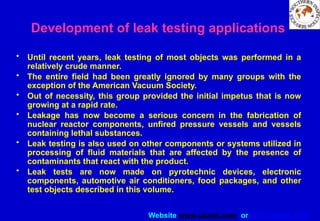
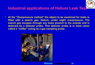
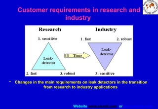
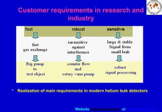
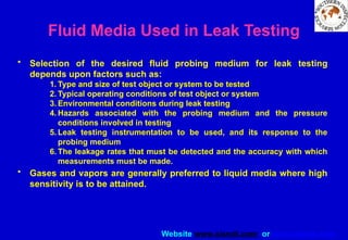


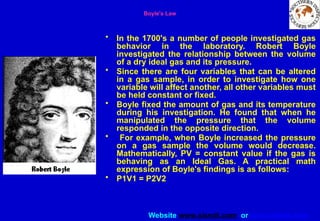


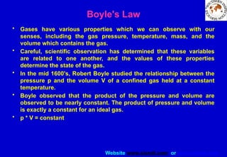
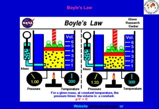
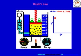
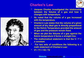
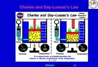
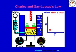
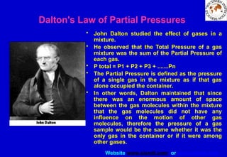
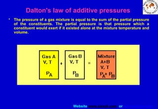
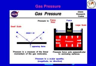
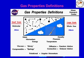
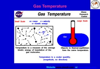

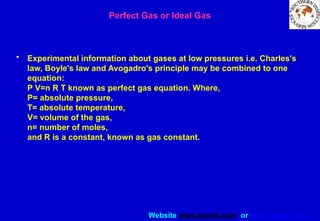
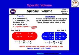
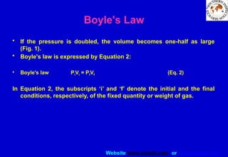
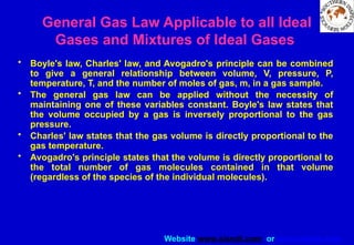
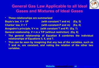
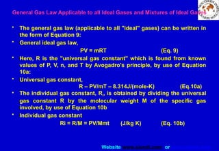
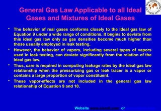
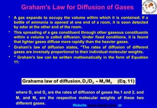


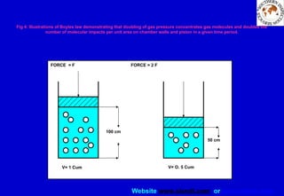
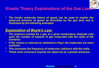
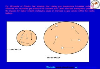

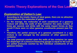
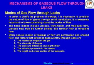


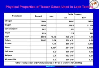
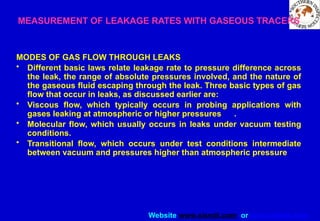
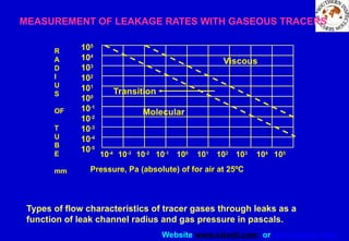


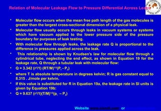

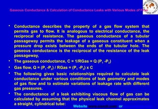


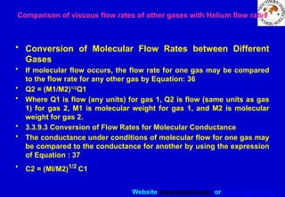
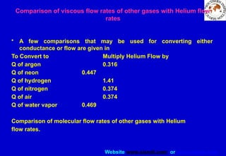


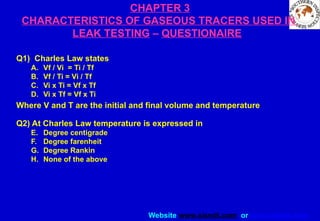


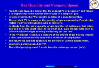

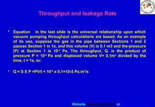


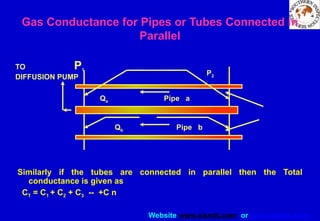
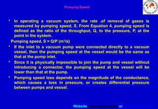

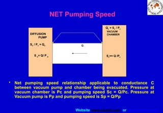
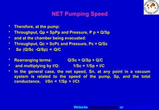

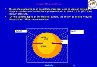


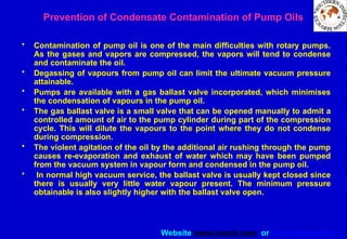
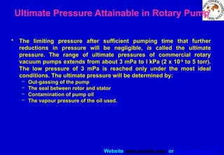
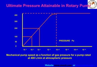

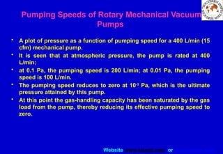

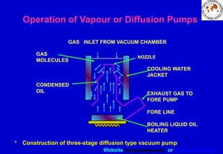
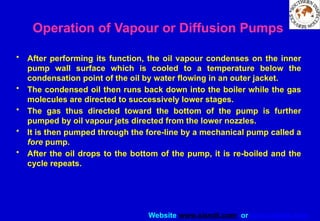
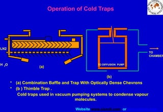
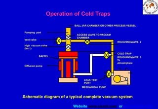


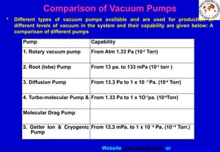
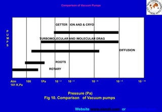
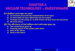


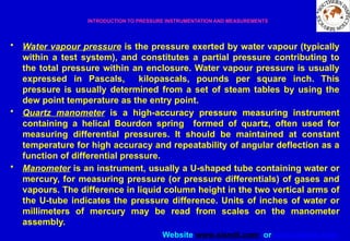
![Website www.sisndt.com or www.ndtsis.com
• K = 273.15 + °C (or rounded. 273 + °c) (Eq. 1)
• and from Fahrenheit temperatures by Equation 2
• K = (459.7 + °F)/1.8 [or rounded (460 + °F)/1.8] (Eq. 2)
• Absolute temperatures in degrees Rankine (ºR) are derived from
temperatures in Fahrenheit degrees by Equation 3:
• °R= 459.67 + °F (or rounded, 460 + °F) (Eq. 3)
• Finally, absolute temperatures in degrees kelvin can be determined
from Rankine temperature values by Equation 4:
• K = °R/1.8 (Eq. 4)
Glossary of Terms Related to Temperature
and Temperature Measurements](https://image.slidesharecdn.com/leaktestingslideshow2-250719065044-edc3c438/85/LEAK-TESTING-SLIDE-SHOW-hbsdfius-osnonsdf-132-320.jpg)
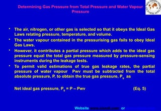

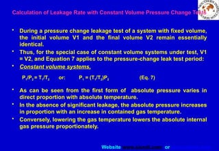
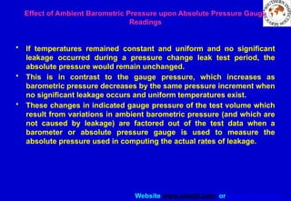
![Website www.sisndt.com or www.ndtsis.com
Correcting Pressure Change Leak Test Data for Changes in Temperature
• When a short-duration pressure hold test is conducted under varying
temperature conditions and requires measurement of both gauge
pressure and temperature, but does not require measurement of
barometric pressure, the barometric pressure is assumed to be one
standard atmosphere (101.3 kPa).
• The pressure loss per unit of time is then determined from the initial
gauge pressure P1 and temperature T1, and the final gauge pressure P2
and final temperature T2, by means of Equation 8. The temperatures must
be absolute temperatures, and the absolute pressures may be taken as
the gauge pressures plus an assumed standard barometric pressure.
• For gauge pressures in kilopascals and temperatures in degrees Celsius,
using SI units and measuring time in seconds, the pressure change rate
is given by Equation 8(a):
DP/Dt = [(P1 + 101) – (P 2 + 101) (T1 + 273) / (T2 + 273)] / Dt (kPa/s) (Eq.8a)](https://image.slidesharecdn.com/leaktestingslideshow2-250719065044-edc3c438/85/LEAK-TESTING-SLIDE-SHOW-hbsdfius-osnonsdf-139-320.jpg)
![Website www.sisndt.com or www.ndtsis.com
• For absolute pressures in kilopascals and temperatures in degrees
Celsius, using SI units and measuring time in seconds:
DP/ Dt = [P1 -P2 (T1 + 273)/(T2 + 273)]/ Dt (kPa/s) (Eq.8b)
• For absolute pressures and absolute temperatures, the correction
takes on the simpler form of Equation: 9
DP/ Dt = [P1 -P2 (T1 /T2)]/ Dt (Eq.9)
• where all terms are expressed in SI units.
Correcting Pressure Change Leak Test Data for Changes in
Temperature](https://image.slidesharecdn.com/leaktestingslideshow2-250719065044-edc3c438/85/LEAK-TESTING-SLIDE-SHOW-hbsdfius-osnonsdf-140-320.jpg)
![Website www.sisndt.com or www.ndtsis.com
Determining Mass of Contained Gas
• The time rates of leakage are determined by the changes in the total
mass of air, nitrogen, or other ideal pressurising gas contained within
the test volume, V, after corrections for temperature, T, and water
vapour pressure, Pv. In the absolute test method, the Ideal Gas Law
can be expressed in the form of Equation 10, for the case in which the
test volume remains constant:
Contained air mass, W = K1 (V/R) [(P – Pv)/T] (Eq.10)
• where W is measured mass of contained (ideal) gas or air, kg; V is
internal free volume of system under test, m3, constant; R is
individual gas constant. (For air, R = 287 J/kg. K, ) P is total absolute
pressure in test volume, ; Pv is partial pressure of water vapour in
contained air, T is mean absolute temperature of air contained in test
volume K 1 ; K1 is I (for SI units). Typically, the leakage rate can be
determined from the change in contained air mass through a
succession of test point data readings or by subtracting the final
mass (at the end of a test period) from the initial contained mass (at
the beginning of the test period)](https://image.slidesharecdn.com/leaktestingslideshow2-250719065044-edc3c438/85/LEAK-TESTING-SLIDE-SHOW-hbsdfius-osnonsdf-141-320.jpg)

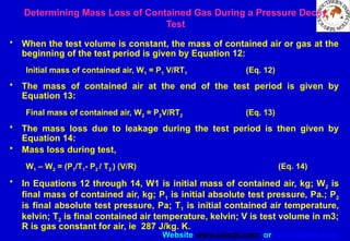
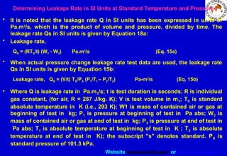

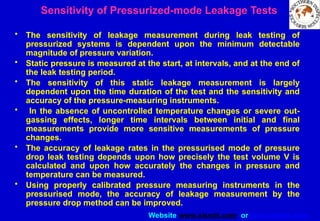
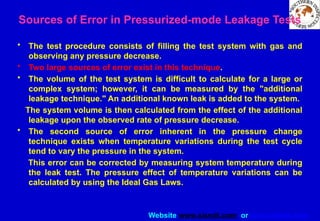

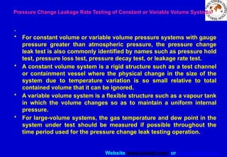
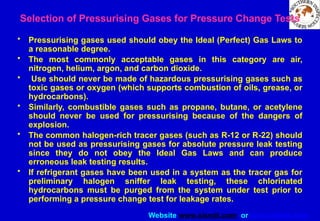
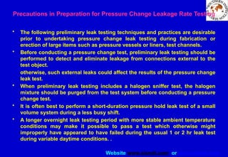
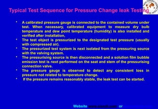
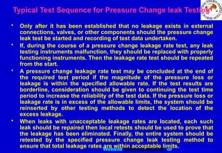

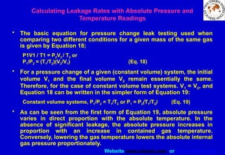


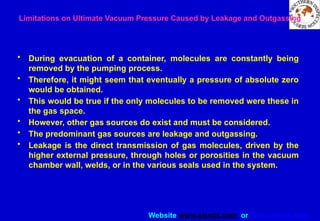
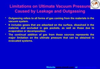
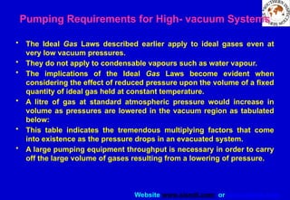
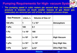


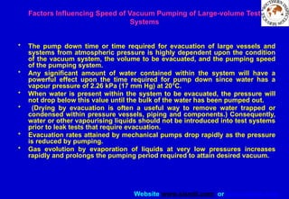

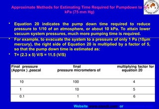

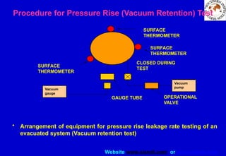
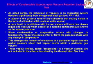
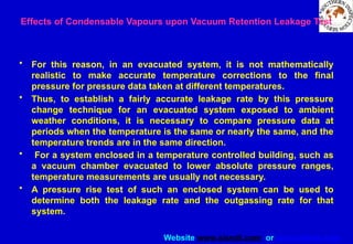
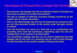
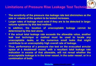
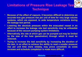


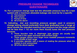


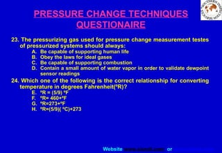
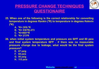

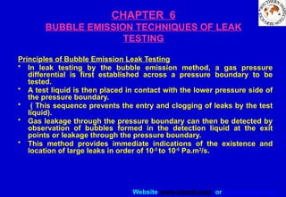
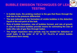
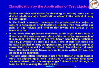
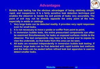
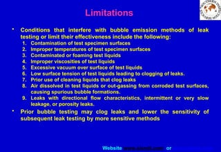
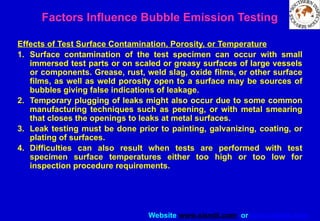

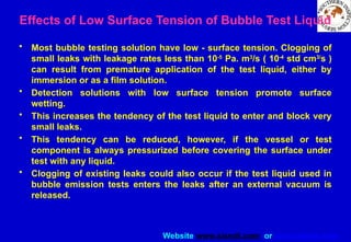

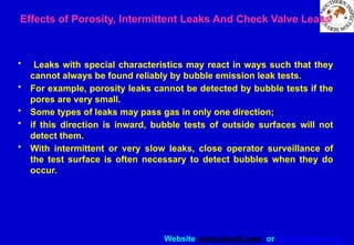
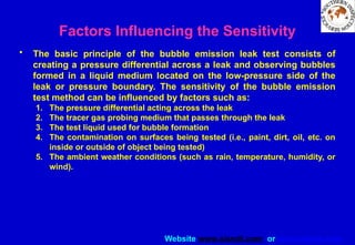
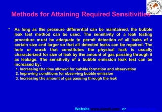
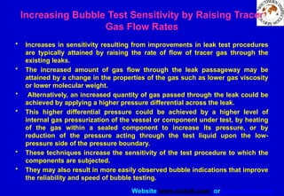
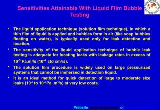
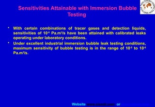
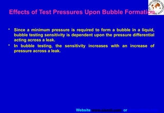
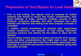
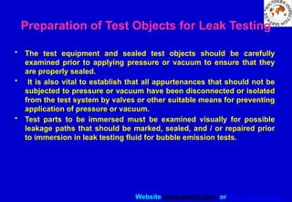
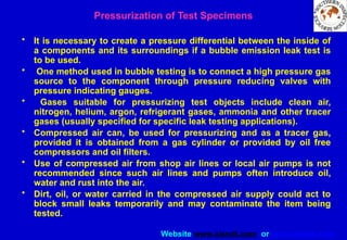
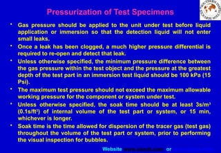
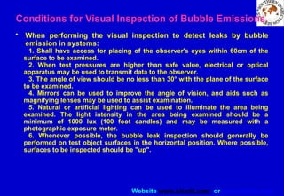
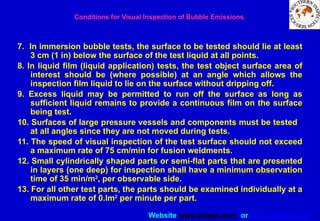
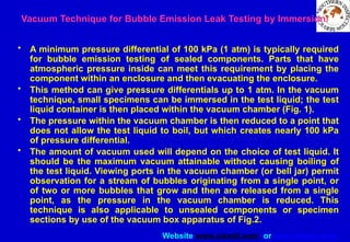
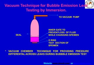
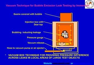
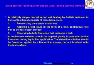
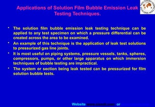

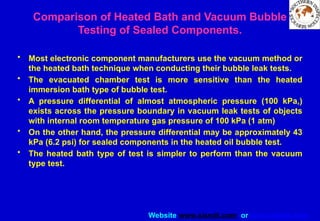
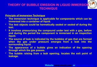

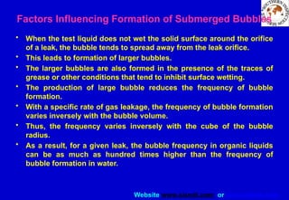


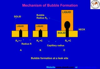
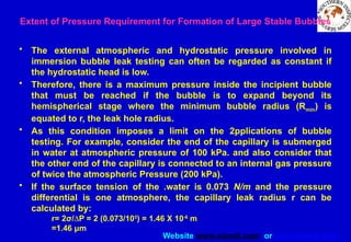


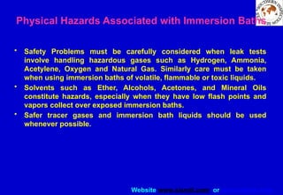
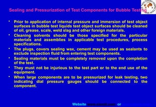
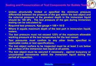
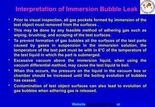
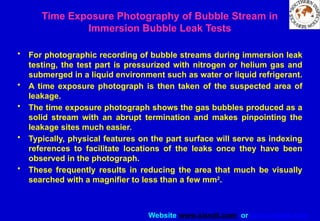
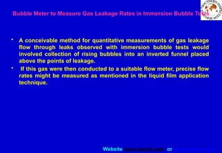
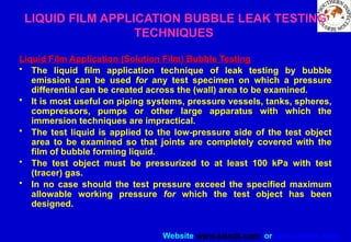
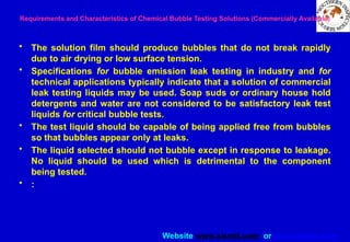

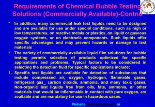

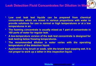

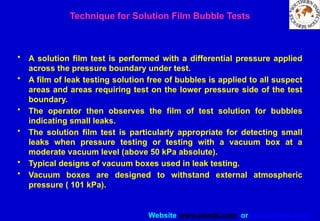
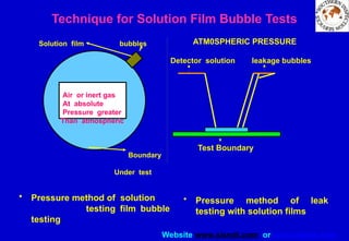
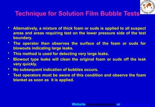
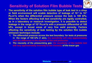

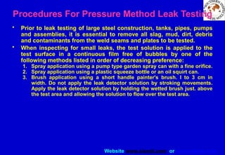
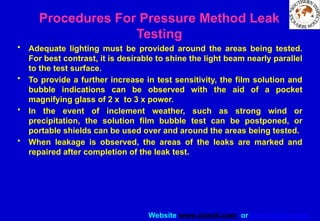
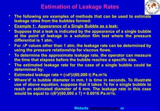


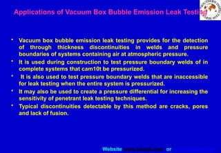
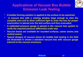


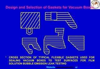
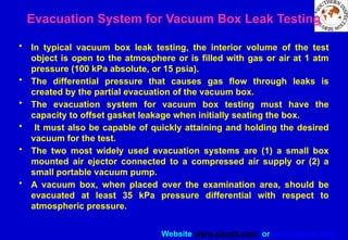
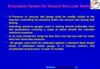
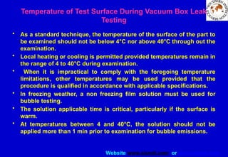
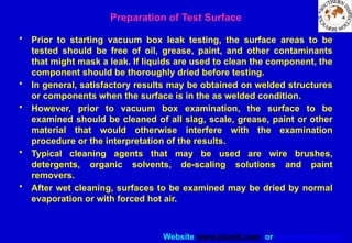
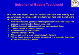
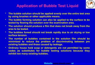

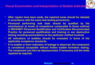

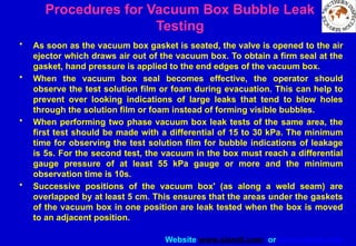
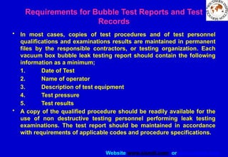


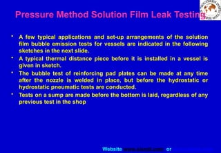
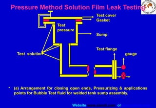
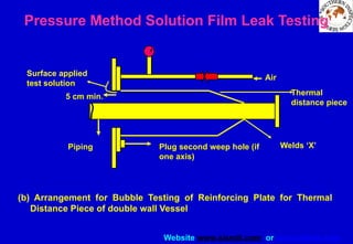

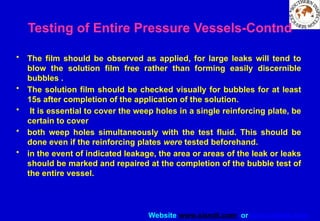

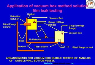
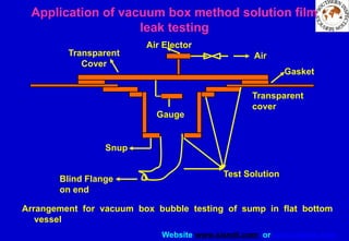

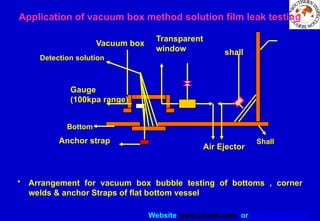
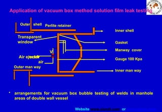
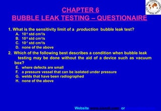
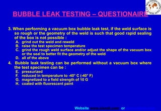
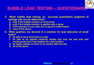
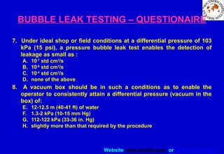
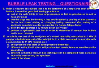
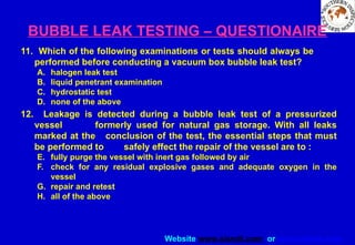
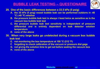
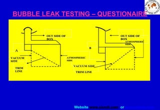


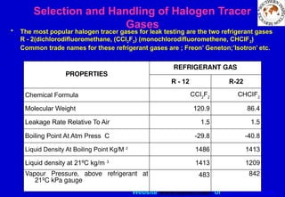
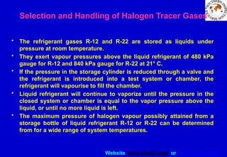
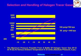
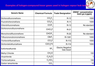
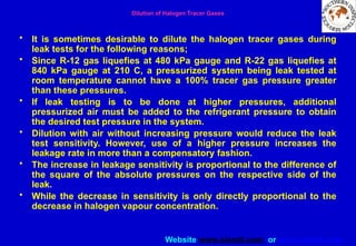
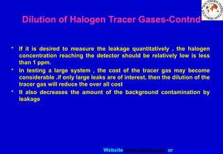
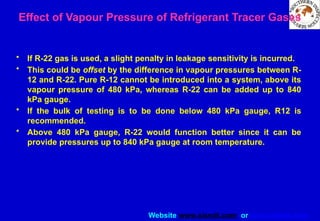
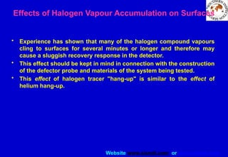
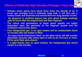
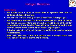
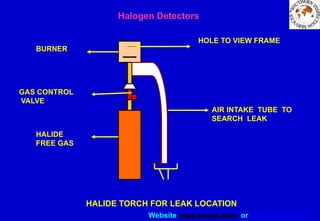
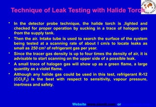
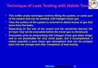
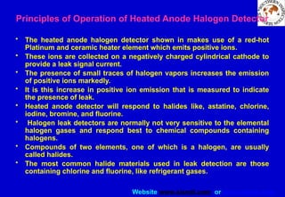
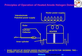
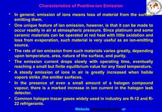
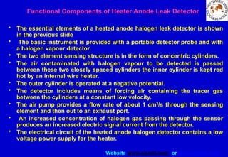
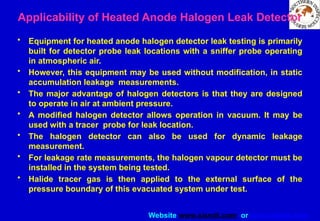


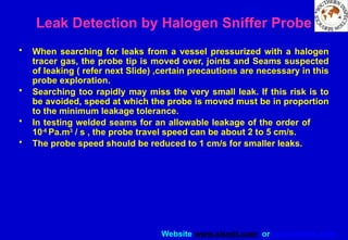
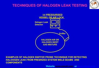
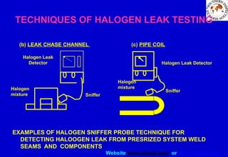
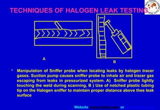
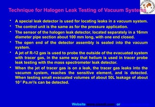
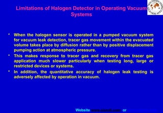
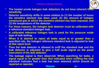
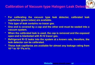
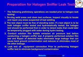
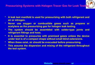
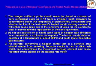
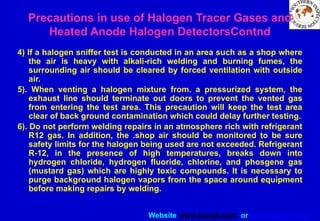
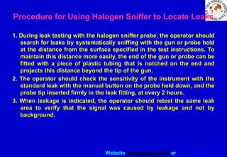
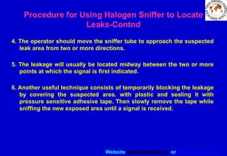
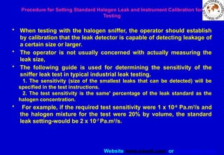
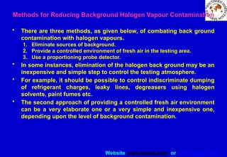
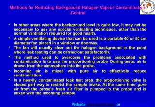
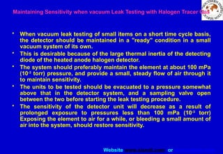
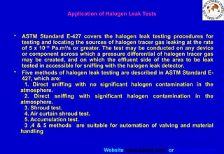
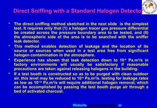
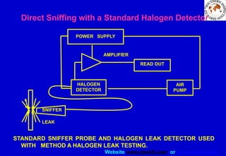

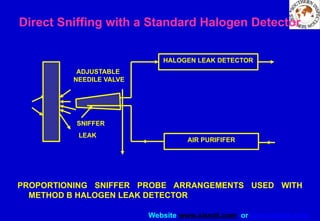
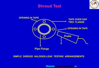
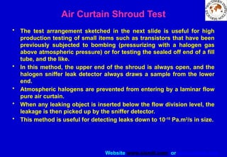
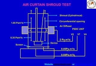
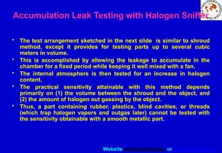
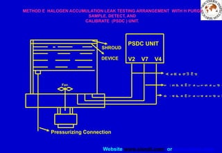
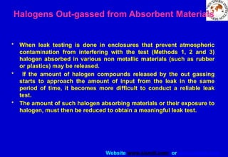
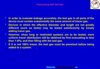
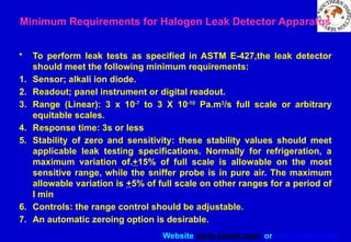
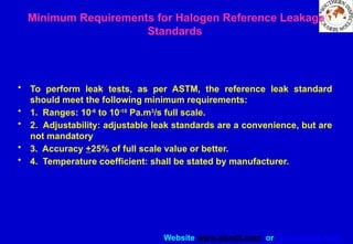
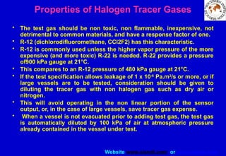
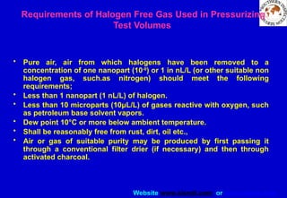
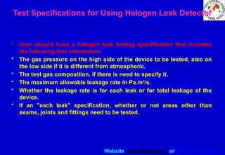
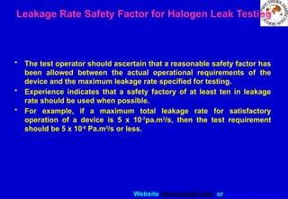
![Website www.sisndt.com or www.ndtsis.com
Correlation of Test Gas Leakage Rates with Leakage Rate of Other Gases or Liquids at
Different Pressures
• Given the normal variation in leak geometry, accurate correlation of
leakage rates with halogen vapors and with other fluids is an
impossibility.
• However, if a safety factory of ten or more is allowed, adequate
correlation for gas leakage within these .
• limits can usually be obtained by assuming viscous flow and using
the equation below:
• Q1 = QO (nl/n2)[(P2
2- P1
2
)/(P4
2
- P3
2
)]
• Where QI is test leakage rate, pa.m3
/s; QO is operational leakage rate,
Pa.m3
/s; n2 is viscosity of test gas, m/s; nl is viscosity of operational
gas, m/s; P2 & PI are absolute pressures on high and low sides during
leak testing, in Pa; and P4, P3 are absolute pressures on high and low
sides in operation, in Pa.](https://image.slidesharecdn.com/leaktestingslideshow2-250719065044-edc3c438/85/LEAK-TESTING-SLIDE-SHOW-hbsdfius-osnonsdf-388-320.jpg)
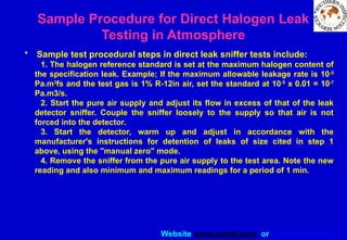
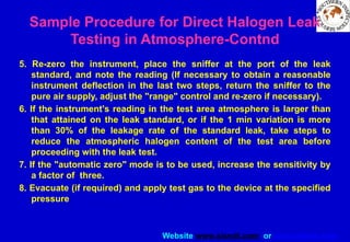
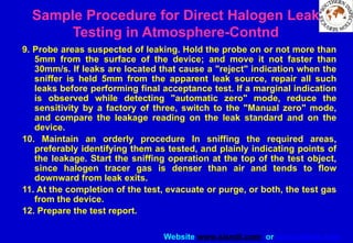
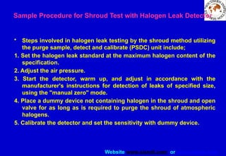
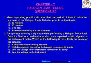
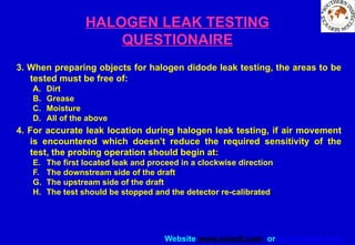
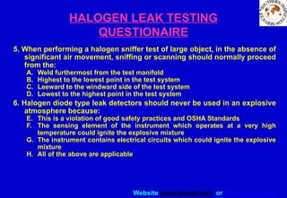


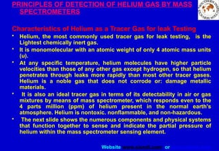

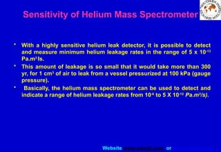
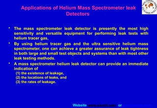
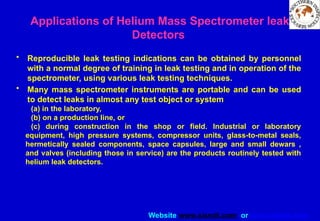
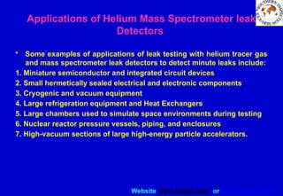

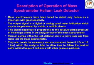

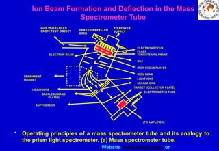


![Website www.sisndt.com or www.ndtsis.com
• Different species of ionized gas molecules are separated by the
transverse magnetic field into a discrete circular paths.
• The leak testing mass spectrometer is tuned for use with a particular
tracer gas by adjusting the electric accelerating field.
• Therefore, a permanent magnet of selected field strength is used to
provide the magnetic field to deflect the positive helium ions only into
a pre-determined circular path.
• When the desired helium ions pass through the slits assembly in the
spectrometer to the collector plate, which collects the positive charge
from each ion to form the ion signal cunent.
• This ion current (milli-amperes) is later amplified and displayed as
visual leak indications on a pane] meter.
Ion Beam Formation and Deflection in the Mass Spectrometer Tube-Contnd](https://image.slidesharecdn.com/leaktestingslideshow2-250719065044-edc3c438/85/LEAK-TESTING-SLIDE-SHOW-hbsdfius-osnonsdf-428-320.jpg)
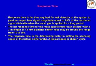

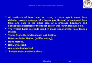
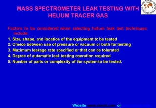
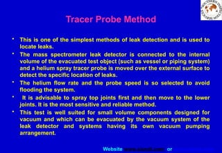
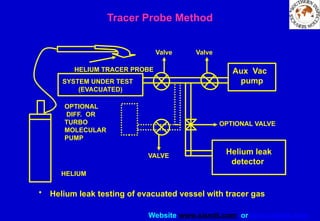
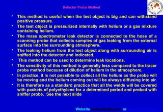
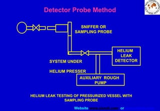
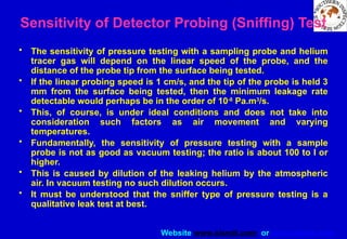
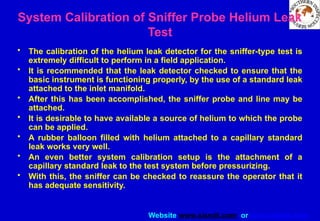

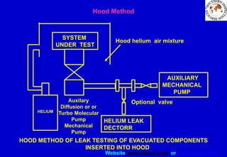
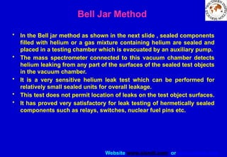
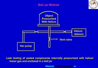
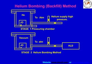
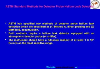
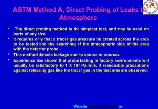
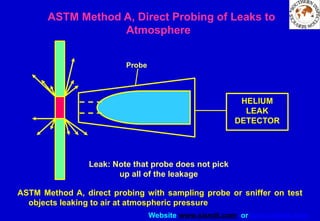
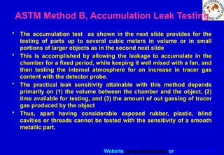
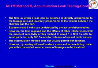
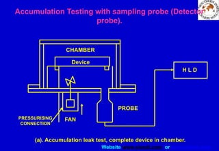
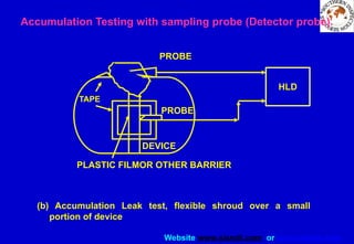
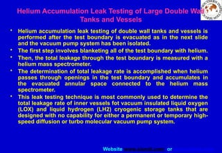
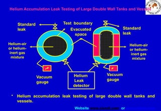

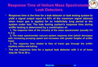

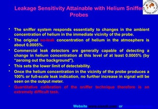
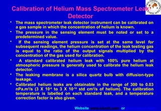
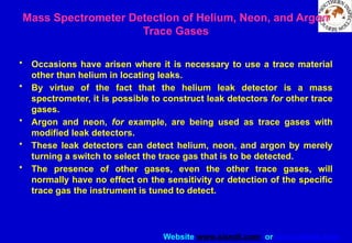


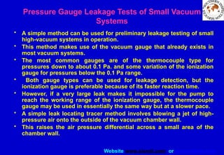

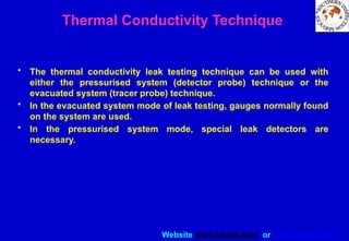


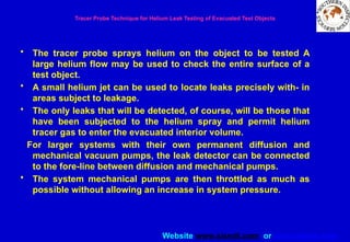
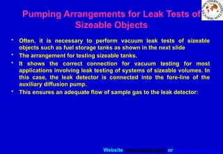
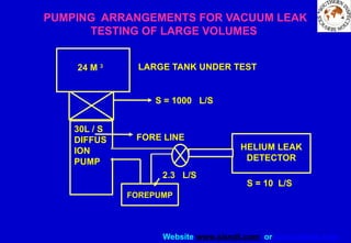
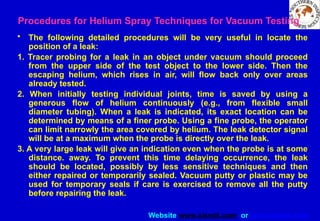
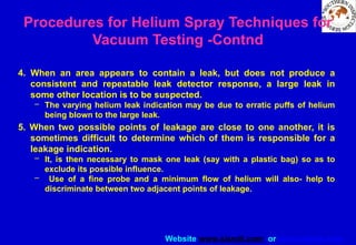
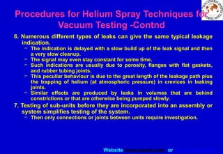

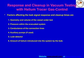
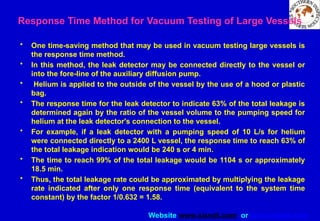
![Website www.sisndt.com or www.ndtsis.com
Measuring Helium Leakage Rates During
Vacuum Testing-Contnd
• The sensitivity of the leak detector, would then be calculated by:
Sensitivity = [(leakage rate)/(output)] x KT
• where sensitivity is helium sensitivity of the leak detector in Pa.m3
/s
per scale division. (% in older units of std cm3
/s, per scale division.
Leakage rate is as specified on standard; helium leak in Pa.m3
/s or in
std cm3
/s. Output is net meter scale divisions, as shown on the output
meter of the instrument for a standard quartz or permeation leak
multiplied by multiplier switch setting. KT is temperature correction,
shown on the standard leak. namely 3% per degree C. Division is
smallest leakage rate meter scale graduation.](https://image.slidesharecdn.com/leaktestingslideshow2-250719065044-edc3c438/85/LEAK-TESTING-SLIDE-SHOW-hbsdfius-osnonsdf-487-320.jpg)