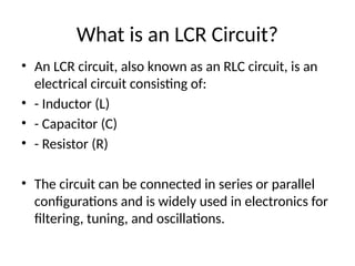
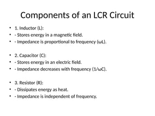
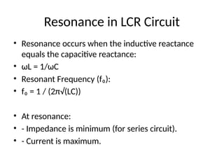
An LCR circuit, also known as an RLC circuit, consists of an inductor, a capacitor, and a resistor, and can be configured in series or parallel. It is widely used in electronics for applications like filtering and tuning, with resonance occurring when inductive reactance equals capacitive reactance. The document outlines the components, resonance conditions, and practical applications of LCR circuits.