Download to read offline

![For accurate measurements of color temperature, use the CL-200A!
Measurement accuracies of CL-200A and photographic color meter
When measuring light sources with non-continuous spectrums such as LEDs, etc., accurate illumination color temperature is
particularly required.The CL-200A can measure color temperature accurately.
CL-200A
The CL-200A has sensors that closely match the color-matching functions defined by the CIE (International Commission on
Illumination), enabling precise color measurement.The measurement results can be displayed in various color notations such
as "Correlated color temperature and uv" according to the application.
Photographic color meter
In order to take more beautiful pictures, it is sometimes necessary to attach filters in front of the camera lens to compensate
for the color of the light illuminating the subject. A photographic color meter is a meter used to select the appropriate filters,
with the sensitivity of its sensors adjusted to match that of the film or digital camera sensor. In addition, because it uses
photographic color temperature, which is calculated based mostly on the blue/red balance of the illumination, large errors
may occur if it is used to measure light sources with non-continuous spectrums.
[Actual measurement data for daylight-color LED bulb]
Color temperature and correlated color temperature
Color temperature
When an ideal blackbody* is heated, it begins to emit light, and as the temperature increases the color of the emitted light
changes from red to yellow to white. Since the color of the emitted light is determined by the temperature of the blackbody,
the color of the light emitted by the blackbody can be expressed as the absolute temperature of the blackbody (in Kelvin).
This color notation scale is called "color temperature". For example, a 7000K color would be the color of the light emitted by
a blackbody heated to 7000K. Figure 1 shows the color of light emitted by a blackbody at various temperatures plotted on an
xy chromaticity diagram. This curve is called the "blackbody locus"; "color temperature" expresses a color on this blackbody
locus.
Correlated color temperature
Since the color of white light emitted by illumination equipment and displays is generally close to the blackbody locus, the
color of such light sources is normally expressed using "color temperature".
However, the color of such light sources is not directly on the blackbody locus. Because of this, a way to enable similar
color expression for colors within a larger region close to the blackbody locus was devised. This is called "correlated color
temperature", and the larger region is shown by the isotherms on the xy chromaticity diagram in Figure 2.
To accurately express the correlated color temperature of a light-source color, it is necessary to state not only the correlated
color temperature but the difference from the blackbody locus, normally in terms of uv.
0.50
0.40
0.45
0.35
0.30
0.25
0.20
0.25 0.30 0.35 0.40 0.45 0.50 0.55
50000
+0.02uv+0.01uv0.00uv0.01uv0.02uv
30000
20000
15000
13000
10000
9000
8000
7000
6000
5000
4500
4000
3500
3000
2500
y
0.90
0.80
0.70
0.60
0.50
0.40
0.30
0.20
0.10
0.00
0.10 0.20 0.30 0.40 0.50 0.60 0.70 x
520
530
540
550
560
570
590
600
610
620
650
680∼780
510
500
490
480
470
460
450 380∼440
200025003000
3500
4000
4500
10000
* *
*
*
**
B
C
A
D55
D65
D75
580
1500
Figure 1: Blackbody locus on xy
chromaticity diagram
Figure 2: Closeup of blackbody locus
on xy chromaticity diagram showing
correlated color temperature region
Measured color temperature
Color-temperature difference from
standard-instrument measured value
Our company's standard instrument 5045 0
CL-200A 5011 -34
Photographic color meter 5600 555
*Blackbody
An ideal radiator. A body which completely
absorbs all incident electromagnetic
radiation. Although a perfect blackbody does
not actually exist, coal is a familiar object
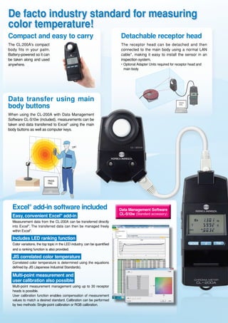
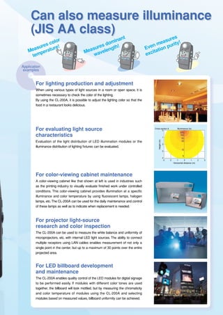
that acts similarly.](https://image.slidesharecdn.com/cl-200a-190613080824/85/Konica-Minolta-Chroma-Meter-CL-200A-4-320.jpg)
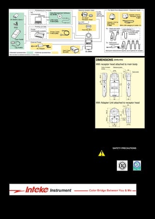

The Chroma Meter CL-200A is a compact, lightweight instrument designed for measuring color temperature, including new light sources like LEDs, with features such as a detachable receptor and easy data management software. It enables multi-point measurements and user calibration, making it suitable for various applications in lighting production, quality control, and color inspection. The device offers precise measurements that align with international color standards, facilitating accurate adjustments in environments like restaurants and color-viewing cabinets.