
Recommended
More Related Content
What's hot
What's hot (20)
Similar to kale amd khandale ic engine (1).pdf
Similar to kale amd khandale ic engine (1).pdf (20)
Recently uploaded
Recently uploaded (20)
kale amd khandale ic engine (1).pdf
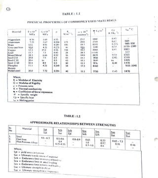
- 1. TABLE: 1.1 PHYSICAL PROPERTIES OF COMMONLY USED MATERIALS CP ImC Kg'm Ex 10 MPa Gx 10 MPa ax 10 nn/mmc Matcrial W/m " K J c 0.45 1800 2710 25.2 ifagncsiun Aluminium Brass Grcy cast Iron Copper Lead Moncl Mctai Steel C15 Steel C 35 Steel C 60 Pbospbet Bronze Nickel steel 4.5 7.25 0.3 35 0.334 0.285 1.69 G60 900-950 1150-1300 1083 327 1325 10 1490 0.27 G.376 0.5.4 0.45 2.67 173 24.0 12.6 4.91 18.7 8210 10.6 16.2 720 10.0 12.3 15.7 0.271 0.26 4.21 46 8 39.0 S 338 13-40 8820 7850 7840 783 0.45 28 26 . 8. 18.3 20.8 6.6 7.9 .32 0.3 0.3 054 G.45 14.0 43 11.1 20.6 to 43 11.1 to 8.9 4.21 1470 910-1040o 20.4 0.3 0.349 40 11.1 0.4 11.1 58 17.3 8160 20.0 7.72 0.291 40 11.1 TIS0 C45 1470 Where, E Modulus of Elasticity G Modulus ofRigidity = Poissons ratio K Thermal conductivity =Coeffficicnt oflinearcxpansion W Specific weight Cp Spccific hcat ImMeltingpoint TABLE: 1.2 APPROXIMATE RELATIONSHIPS BETWEEN STRENGTHS |Sr. No Matcrial S Scb Seb S Syt Sea Scb Ses Sch Sus Sut Sut Sut Suc Stcci Cast iron Non Ferrous Alloys Sut 0.6-0.7 0.5-0.6 0.8-0.9 0.65 0.55 0.9 0.8 0.65 7.5 0.31 0.4 1.0 0.25-0.3S 0.7-1.0 0.16 where, Syt = yicld stress in tension Sut Ullimate tensile stress f matcrial Scb Endurance limit in reversed bend:n Sca Endurancclimitin aual lwading Scs Endurancc limit in torsinal loadi Sus = Ullimalc strength in shear Suc =Ullimate streng1h in cmpressi
- 2. CHAPTER3 VALUES OF PERFORMANCE PARAMETERS TABLE:3. Compression Ratio (R) Diesel Engine TypcofEngine S.No. Petrol Engine R ON R Diesel engine with open chambers Swril Chamber 1 66-72 5.5 -7.0 14-17 2. 72-76 7.7-7.5 16-20 diesel cngines 3. 76-85 7.5-8.5 Pre - combustion 16.5-21 chamber dicsel engine Super chargcd diescl engine 85-100 8.5 10.5 11-17 Where R =Compression ratio ON = Octanenumberof petrol fucl TABLE:3.2 INDICA1ED MEAN EFFECTIVE PRESSURES (Pim) S.No Type Pressure, MPa| 0.60 to1.40o Four stroke petrol engine Four stroke diesel 1. 2 0.70 to 1.1 engine Four stroke super charged dieselchgine 3. up to 2.2 TABLE:3.3 INDICATED THERMAL EFFICIENCY (7thi) Type ofengine Thermal Efficiency (% S.No. 1. Petrol engine Diesel engine 26 38-50 35 2. TABLE:3.4 INDICATED SPECIFIC FUEL CONSUMPTiON (ISFCD S.No. Typc ofengine ISFC, kg/hr-kw Pctrol engine Dicsel cnginc 1. 0.24 0.32 0.17 0.23 2.
- 3. TABLE 3.5 MECHANICAL EFFICIENCY (n m) Mechanical Efficicncy() S.No. Tye of engine 70-90 Two/four strokepetral engine 70-82 2. Four stroke diesel enginc 70-85 . Twostrokedicselengine TABLE 3.6 RORE DIAMETER Standard cylinder bore, D,mm. S.No. Type of engine Borc liam:ter inmn Pclrol engine for car -1000 30, 32, 36, 38, 40,42, 45, Petrol enginefor bucks Tractor diesel cnginc 50, 52, 56,58,60,63,68,70,75 80, 85, 90, 95, 100,105, 110, 1i5, 120,125,130, 140, 145 150, 160, 170, 180,190,200,210 2. 70-114 . 70-150 Automobile dieselengin 80-130 TABLE3.7 STROKE TO BORE RATIO (SD) S.No. Type ofengine SD 1. Pctrol cngine 0.7 1.0 2. Diesel engine 0.9-1.2 3. Tractor diesclengincs 1.1-1.3 TABLE 3.8 MEAN PISTON SPEED (Vpm) S.No. Typc ol engine Mean Piston specd M/sec| Pclrol cngine for car Pctrol engine forbluck Aulomobile dicsel engin¢ Tractor dicsel cnginc 12-15 9-12 2. 3. 6.5 - 12 5.5-105
- 4. TABLE:3.9 ENGINE PERFORMANCE RELATIONS SNo. DESCRIPTION RELATIONS Mcchanical Efñiciency, 7m ,% 7mPx100 1. where P - brake power in KW Pi-IndictedpowerinKW PiPim LANIne XIoS Pim actual meanindicatedelfective pressure, N/m* (Ref. table 3.2 ) L StrokcLength, m A Bore arca,m Ni N/2, four stroke - N, Two strukc N Spced,RPS ncno. olcylin:lers. PimPimtX f 8 where 2. Actual Indicated Mean cffective Pressure, Pim, N/m f diagamfactor = 0.94 to 0.98, for petrol engine = 0.92 to0.95,for dicscl engine Pimt-Thcoreticalindicatcd. mean cffective pressurec,N/m a)forpctrolcngine: P(R)I1-R-]+Ps[1]- Pimt (-1) (R-1) where r adiabalicindex = 14 R Compressionratio (ReferT:3.1) P1=Suctionpressure,N/m P3- Maxaimumgaspressure,N/m =Pmax b) ForDieselengine P2= R'P1 Where, P2 MaxGas pressure=Pmax Pcutoffratio PR(1-R)+ R'(p-1)] T-1 Piont (R-1) Indicated specific fuel ISFC= BSFC m consumption, ISFC, kg/hr-kW where, BSFC Brake specific fvel consumption, kg/hr-kw 7m-Mecbanical cfficiency.
- 5. CHAPTER:4 DESIGN OF ENGINE PARTS TABLE 4.1 RISTON DESIGN Sr. No DESCRIPTION Piston Materials DETAILS | RELTiON 1. Iype Allowable stress,Sd,MPa Cast Iron 35-40 Alloy steel Aluminium 160-100 50-90 Crown thickness, te, in mm Pmax 1/2 a) Max Pressure criteia: where; D Diameter of piston, mm, Pmax Maximum Gas pressure, MPa Sa Allowablestress, MP b) Thermal stress criteria 9D x 10 16 C14T wiere, te crown thickncss, cm Ci Heal conduction factor KJ/cm-hr-°C - 0.56, for CI,steel - 1.986,for Aluminium. AT Temperature difference between the centre and edge of pison head 220° Cfor CI &steelS 75°Cfor Aluminimum 9-HHcar urilowingthrough crown,KJ/hr-c = KxBSFCxCyxPg/A.Dc_ K fraction of heat evolved reaching to crown surface =0.05-0.1 Pa- Brake pqwer,KW(ReferT:3.4,3.9) BSFC BrakeSpecificfucl consumption Kg/hr-KW Cv-Calorific valueoffuel, KJkg -40500-.32000 kJ/kg, Petrolfuel - 42000 4000 kJkg, Diesel fuel A AreaofPiston,cm neno.ofcylinders le 0.032 D+1.5, mm. hX iSFC c)Empitical Relatioa:
- 6. TABLE:4.2 DESIGN OF PISTON RINGS ST.NO. DESCRIPTION RELATIONS Radial thickness of piston ring, tr ,mm D . t a) BearingPressure criteria where, Pw Radial wallpressure, -0.0245-0.042,N/mm Sa-PermissibleStres, - 84-112,N/mm,forCI tr(0.04-0.045) D,for compression ring - (0.038-0.043) D, for oil control ring. b) Empirical Relation n 0.4/D where, 2. Numbers of Piston rings, n D Bore diameter, mm n 34, for automoticengines 5-7, for stationary compression ignition engines. 3. Axial thickncss ofPistonring,tam, mm a) Minimum axial thickness,tam tam D/10.0 b) Empirical relation l-(0.6to1.0)t 4 Stress in piston ring section when 1.6x Exlr Sc D-t+ slipped over piston, Sc, MPa where, Kr- Ring gap when ring is being slipped on thepiston,mm E - Modulus of.Elasticity (Refer T: 1.2) Sc 180MPa. x Io 5. Gap between the free ring ends, G1, mm G1 (3.5-4)!r Gap between the ring ends when the ringis in the cylinder, G2, mm 6. G2 (0.002-0.004)D 7. Thickness between ring grooves i.c. land, tv,mm (0.75-1.0) ta