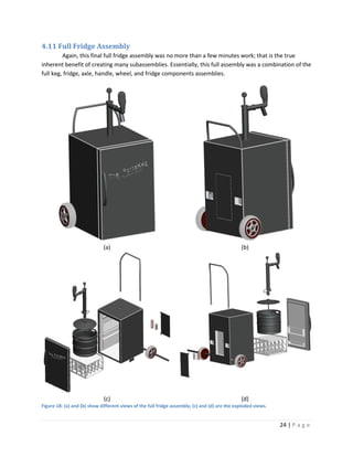
The document appears to be a final design project report for a portable kegerator called the PortaKeg. It includes sections on researching existing products, developing alternative designs, choosing a final design, 3D CAD modeling of the design, manufacturing analysis, and conclusions. The design goals were for the kegerator to be portable, simple to use, durable, and low-cost. Three alternative designs were considered before the author selected Design 1 to model in detail with CAD software. The report provides details on modeling different subassemblies that make up the full kegerator design.
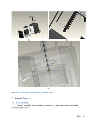
![(a) (b)
(c)
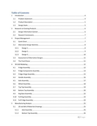
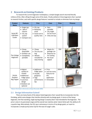
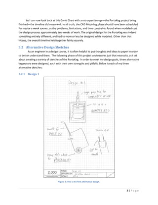
Figure 32: Rendered views of (a) the fridge assembly, (b) the fridge components, and (c) the axle and wheel.
6.2 Animation
The final use of ProE throughout this entire project came in terms of creating a design animation
movie. Utilizing the Animation toolbar within ProE allowed sundry amounts of options to be included in
the film. The movie showcased the various views of the PortaKeg, how each subassembly is attached to
the full assembly, how each subassembly is constructed, how the tap pump works, the pull-out
handle/dolly system works, and [supposedly] how the wheels work. Unfortunately, I could never
understand why my wheels rotate they way they do; it’s as if they decide to rotate about a collection of
five or so imaginary axes. Also, the sheer amount of power required to create a photorealistic movie file
is too much to handle for the computing machines we have available at the University at Buffalo. My
longest “successful” rendered video only created 15 seconds of film (out of two and a half minutes).
Although this depiction sure does look swell, the amount of effort needed to doctor up a halfway decent
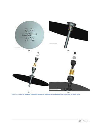
movie. Both movies can be found at my CAD website, sited in the references at the end of this report.
38 | P a g e](https://image.slidesharecdn.com/jonathanjonesmae377finalprojectreport-091214022854-phpapp01/85/Jonathan-Jones-Mae377-Final-Project-Report-38-320.jpg)
![pressure in the keg and forced the beer out through the nozzle. A working Manikin application within
ProE would have been nice too, as I could show how the dolly works in comparison to a human and so
on. Finally, I would love to understand why anything that has to rotate around an axis within the
animation process never, ever works. It is a very low point in my movie, and something I would very
much have like to have corrected. But alas, I am only one man with one brain with only so very little
time.
Moving on to the topic of very large bones I have to pick with this project, I would like to start
with the general overkill in terms of file creation. Finally, after utilizing a .easm file in PowerPoint, do I
see the inherent usefulness of that particular file extension. However, .htm, .pdf copies of the 2D
drawings, the [entire] animation process to be truthful were a bit much. The animation process is a
great idea in concept, and something that should undoubtedly be taught, but for god sakes have
competent hardware and software so us poor students. Pro/ENGINEER is a woefully lacking program in
this respect, their animation program indeed coining the phrase “okay, now what is the exact opposite
thing I want to do? Do it, and the program should work.” Many, many a long day and night was wasted
trying to get the program to respond, work, or simply save my work correctly. In all honestly, if I could
go back and do it all over again, I would, but in an entirely different program. The real world wants
SolidWorks, so for god’s sake teach me SolidWorks.
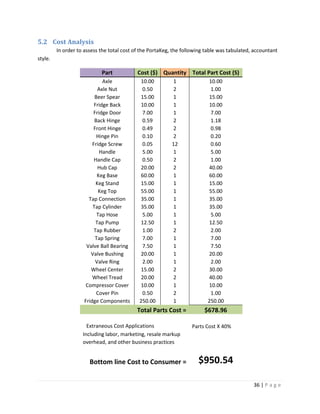
8.2 Conclusion
This final design project of the PortaKeg was a completely different experience than any I have
ever had. Taking a product from its inception, changes, physical manifestation, application,
manufacturing analyses, presentation, until the end of its expected life is a very unique occurrence. I feel
that with the completion of this project, as well as my design course, I have made great strides on my
way to becoming a successful engineer, let’s keep this train rolling.
9 References
1.) "The German Keg King." Wikimedia. Web. 14 Dec. 2009.
<http://upload.wikimedia.org/wikipedia/commons/2/2f/Keg_geschnitten.jpg>.
2.) "Haier Refrigerated Direct Draw Tappers." Keg Man. Web. 14 Dec. 2009. <http://tap-a-
keg.com/haier_kegger.html>.
3.) "Kegerator Reviews." Hops Aficionado. Web. 14 Dec. 2009.
<http://www.hopsaficionado.com/kegerators.html>.
4.) S System - Keg Coupler - Tap w/ Blue Lever Handle. Web. 14 Dec. 2009.
<http://www.micromatic.com/draft-keg-beer/keg-taps-couplers-pid-7486E.html>.
41 | P a g e](https://image.slidesharecdn.com/jonathanjonesmae377finalprojectreport-091214022854-phpapp01/85/Jonathan-Jones-Mae377-Final-Project-Report-41-320.jpg)