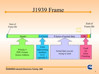
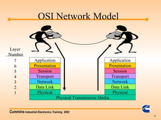
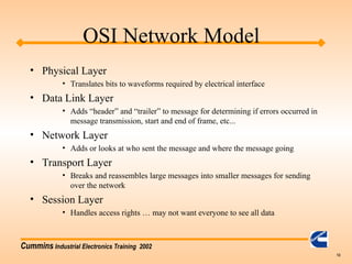
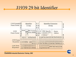
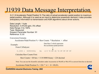
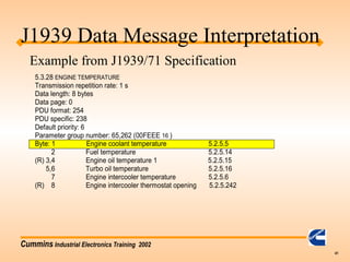
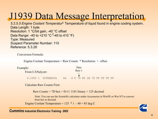
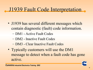
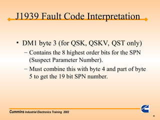
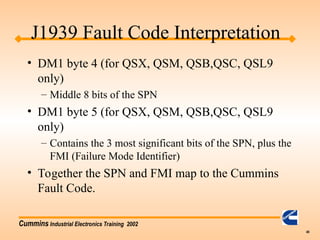
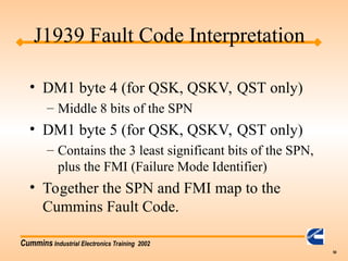
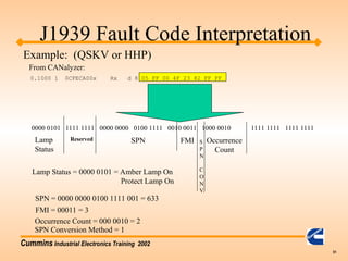
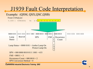
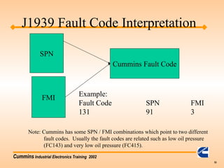
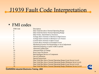
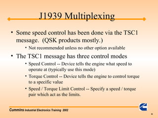
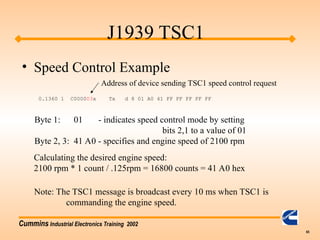
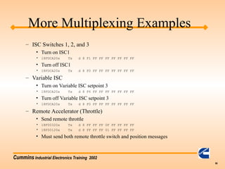
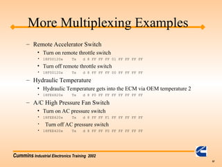
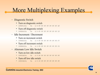
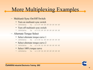
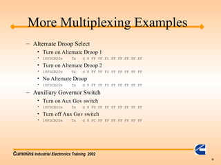
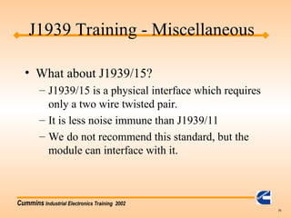
Cummins Industrial Electronics Training 2002
1
• Agenda
– Basic Training: J1939 Vocabulary
– Basic Training: Monitoring
– Basic Training: Control
– Basic Training: Tools / Information
– Advanced: J1939 message breakdown
– Advanced: J1939 diagnostic messages
– Advanced: J1939 multiplexing
J1939 Training
Cummins Industrial Electronics Training 2002
2
• Vocabulary:
– Datalink: Term used to describe how devices
communicate with each other also referred to as a
network.
– Bit: One binary value. A “1” or “0”
– Byte: 8 bits put together. Ex: “00000001”
– Bit Field: Number of bits which are grouped
together
– CAN Data Frame: Series of ordered bit fields
J1939 Training
Cummins Industrial Electronics Training 2002
3
• Vocabulary (cont.)
– Cyclic Redundancy Check (CRC): Error
control mechanism used to detect when a
message was corrupted during transimission.
– Data Field: 0-64 bit field in the CAN data
frame which contains the actual data such as oil
pressure or coolant temperature as defined in
J1939/71 standard.
J1939 Training
Cummins Industrial Electronics Training 2002
4
• Vocabulary (cont.)
– Destination Address: Address of who is suppose
to receive the message. (not included in all J1939
messages)
» Global Address is 255 or FF hex
– Device: Any physical component which listens
to or sends information out on the J1939
datalink.
– Electronic Control Unit: same as a device
J1939 Training
Cummins Industrial Electronics Training 2002
5
• Vocabulary (cont.)
– End of Frame: 7 bit field which marks the end of a
CAN frame
– Extended Frame: A CAN frame which contains a 29
bit identifier as defined in the CAN2.0B standard.
» Note: J1939 allows both 11bit and 29 bit Identifers to
coexist on the same network.
– Frame: A series of data bits making up a complete
message. The frame contains several bit fields
J1939 Training
Cummins Industrial Electronics Training 2002
6
Header # of bytes 8 bytes of actual data CRC
Start of
Frame Bit
ACK
Field
End of
Frame Bit
Priority #
PDU Format
Source Address
4 bits
representing
numbers
0-15
typically 8
Actual data you are
trying to send
Used
for
Error
Checking
J1939 Frame
Cummins Industrial Electronics Training 2002
7
• Vocabulary (cont.)
– Message: One or more CAN data frames which
transfer a complete piece of information to other
devices on the datalink.
– Multipacket Message: Messages which require
multiple CAN data frames. These are handled by
the “transport protocol”.
– Protocol: A protocol is the “language” of how to
communicate between devices.
J1939 Training
Cummins Industrial Electronics Training 2002
8
• Vocabulary (cont.)
– Parameter Group Number (PGN): a 24 bit
identifier used to identify a message which
contains a particular group of parameters.
– Parameter Group: A collection of parameters
that are conveyed in a J1939 message.
– PDU1 Format: Format used when specifying a
destination address
J1939 Training
Cummins Industrial Electronics Training 2002
9
• Vocabulary (cont.)
– PDU2 Format: Format used when broadcasting
information.
– Priority: The highest priority is zero. Lowest
priority is seven.
– Source Address: Address of who is sending the
message on the datalink.
– Start of Frame: Bit used to indicate the start of a
CAN frame.
J1939 Training
Cummins Industrial Electronics Training 2002
10
• Vocabulary (Cont.)
– Suspect Parameter Number (SPN): The
particular element which is having a problem.
This is used in the fault codes to tell us which
part is having a problem. (Sensor, ECM, etc..)
– Failure Mode Identifer (FMI): Used to say how
a particular SPN has failed.
J1939 Training
Cummins Industrial Electronics Training 2002
11
J1939 Training
Cummins Industrial Electronics Training 2002
12
Physical Transmission Media
Physical
Data Link
Network
Transport
Session
Presentation
Application
Physical
Data Link
Network
Transport
Session
Presentation
Application
Layer
Number
7
6
5
4
3
2
1
OSI Network Model
Cummins Industrial Electronics Training 2002
13
• Physical Layer
• Translates bits to waveforms required by electrical interface
• Data Link Layer
• Adds “header” and “trailer” to message for determining if errors occurred in
message transmission, start and end of frame, etc...
• Network Layer
• Adds or looks at who sent the message and where the message going
• Transport Layer
• Breaks and reassembles large messages into smaller messages for sending
over the network
• Session Layer
• Handles access rights … may not want everyone to see all data
OSI Network Model
Cummins Industrial Electronics Training 2002
14
• Presentation Layer
• Data encryption, data compression, etc...
• Application Layer
• Whatever is left over from other layers….
OSI Network Model
Cummins Industrial Electronics Training 2002
15
• Most protocols do not specify each layer of
the OSI model. J1939 does not specify
each layer of the model.
• Currently the following layers are given
specific documents in the J1939 standard
Layer 1 -- J1939/11
Layer 2 -- J1939/21
Layer 3 -- J1939/31
Layer 7 -- J1939/71 & /73
OSI Network Model
Cummins Industrial Electronics Training 2002
16
• What can I monitor?
• What must I monitor to remove the
indicator lights?
• Where do I find out how to interpret the
messages?
• Example of reading oil pressure
J1939 Training
Cummins Industrial Electronics Training 2002
17
All Module Information
Broadcast
Data
Request
Only
Data
J1939 Training
Cummins Industrial Electronics Training 2002
18
• What can I monitor?
– Sensor parameters such as coolant temperature,
oil pressure, etc…
– Engine Fault Codes
J1939 Training
Cummins Industrial Electronics Training 2002
19
• What must I monitor to remove the
indicator lights?
– All fault code SPNs (suspect parameter number
and FMIs (failure mode indicator) must be
displayed.
J1939 Training
Cummins Industrial Electronics Training 2002
20
• Where do I find out how to interpret the
messages?
– Parameter data messages are found in the J1939/71
standard. Find the PGN first then look up the
individual parameter definitions.
– Fault Code (Diagnostic) messages are found in the
J1939/73 standard. You will also need to use the
wiring diagram, or AEB for the specific engine to
understand what Cummins fault code goes with a
SPN / FMI pair.
J1939 Training
Cummins Industrial Electronics Training 2002
21
J1939 Control
• What can the customer control?
– Engine speed can be controlled via the J1939
datalink.
– Fan Clutch
Cummins Industrial Electronics Training 2002
22
• High Speed datalinks
– Reflections & Terminations
– Topology
– Troubleshooting
J1939 Training
Cummins Industrial Electronics Training 2002
23
• Reflections & Terminations
– Terminations are required to minimize reflections
on the datalink (demo)
– J1939/11 requires two 120ohm terminations for
the datalink.
– EA options for QSX/QSM only use one 120ohm
termination due to the short length between the
ECM and the service datalink connection.
• ICAD Database has more detailed information
J1939 Training
Cummins Industrial Electronics Training 2002
24
• Circuit block diagram
– Most of our modules use the Intel 82527 Serial
Communcations Controller ( CM500, CENSE,
CM550, CM570, etc...)
– Example circuits shown in J1939/11
specification
ESD
Protection
Circuit
CAN
Transceiver
Serial
Communications
Controller
Micro
( 68332 )
J1939 Training
Outside
ECM
Inside
ECM
Cummins Industrial Electronics Training 2002
25
120Ώ
Length of Backbone: .1 - 40m
Length of Stub: 0 - 1m
Maximum number of nodes: 30
Terminations : 120Ω
Minimum Spacing: 0.1 m Note: Do not equally
space the node connections
on the backbone
120Ώ
J1939 Topology
Stub
Backbone
Cummins Industrial Electronics Training 2002
26
• Dynamic Addressing
– Each ECM on the network takes on an address
at startup. The specific address may be
different from startup to startup.
• Cummins does not support dynamic
addressing; therefore, make sure each
device on the datalink has a unique address.
J1939 Addressing
Cummins Industrial Electronics Training 2002
27
• Troubleshooting
– First check the termination resistors.
• Measure resistance between CAN_H and CAN_L.
• Resistance should be approximately 60 ohms. If
you have a small backbone like in the EA options,
this may be closer to 120 ohms.
– Check for frame errors
• Using CANalyzer or other tool, monitor the J1939
datalink to see if any frame errors are recorded.
J1939 Troubleshooting
Cummins Industrial Electronics Training 2002
28
• Troubleshooting (cont.)
– Monitor broadcast parameters using CANalyzer
– For multiplexed parameters, verify that the
OEM / DOEM is sending the correct source
address in the message.
– Unplug other devices from the datalink so only
the PC and ECM are on the network.
J1939 Troubleshooting
Cummins Industrial Electronics Training 2002
29
• Tools
– Protocol analyzer
• Must have a protocol analyzer to develop a datalink
interface.
• Must have the J1939 standard unless customer
already has good familiarity with CAN 2.0B
protocol.
J1939 Tools
Cummins Industrial Electronics Training 2002
30
– CANalyzer
» In North America contact: Vector CANtech Inc.
(248) 449-9290
Matt Palmer
» Outside America contact:
49-711-80670-505
Lother Felbinger
» Approximate Cost:
Software: $2,700
Hardware: $1,185
J1939 Tools
Cummins Industrial Electronics Training 2002
31
– Jpro
» Cummins owned distributors: Software available
through engineering tools (see intranet site:
etools.ctg.cummins.com) Hardware available through
Industrial Communication Technologies.
» North America: call (978) 499 - 9271
» Outside North America: 49 89 46 1090
» Appoximate costs: $910
» Non Cummins owned distributors: Software is NOT
available through engineering tools. Recommend
CANalyzer
» Jpro support from manufacturer ends 12/01.
J1939 Tools
Cummins Industrial Electronics Training 2002
32
• Quick Check II available 4th Qtr 2001
– J1939 specification
• Can be ordered online at www.sae.org for $495.00
USD for non-SAE members and $395.00 USD for
SAE members.
J1939 Tools
Cummins Industrial Electronics Training 2002
33
J1939 Message Breakdown
Cummins Industrial Electronics Training 2002
34
Header # of bytes 8 bytes of actual data CRC
Start of
Frame Bit
ACK
Field
End of
Frame Bit
Priority #
PDU Format
Source Address
4 bits
representing
numbers
0-15
typically 8
Actual data you are
trying to send
Used
for
Error
Checking
J1939 Frame
Cummins Industrial Electronics Training 2002
35
CAN Extended
Frame Format
J1939
Frame Format
J1939 Frame
bit position
CAN 29 bit
ID position
1
S
O
F
S
O
F
3 1
2
2 3 4
2
8
2
6
2
7
8 7 6 5 4 3
PDU Format
6 bits (MSB)
S
R
R
I
D
E
P
F
2 18 7 6 5 4 3 2 1 8 7 6 5 4 3 2 1
Priority
RD
P
PDU Specific
Destination Address,
Group Ext, or
Proprietary
Source
Address
Identifier
11 bits
Identifier Extension
18 bits
S
R
R
I
D
E
R
T
R
R
T
R
56
7
8 9 1
0
1
1
1
2
1
3
1
4
1
5
1
6
1
7
1
8
1
9
2
0
2
1
2
2
2
3
2
4
2
5
2
6
2
7
2
8
2
9
3
0
3
1
3
2
3
3
2
5
2
4
2
3
2
2
2
1
2
0
1
9
1
8
1
7
1
6
1
5
1
4
1
3
1
2
1
1
1
0
9 8 6 5 4 3 2 1 0
J1939 29 bit Identifier
Cummins Industrial Electronics Training 2002
36
1 8 F E D F 0 2
1 1000 1111 1110 1101 1111 0000 0010
3 bits
Priority
Number
Reserved
Data
Pag
e
PDU Format (PF)
PDU Specific (PS)
Contains Destination
Address if PF <239
Source Address
Header Breakdown (29 bits)
J1939 29 bit Identifier
Cummins Industrial Electronics Training 2002
37
• Looking at data messages on the
CANalyzer.
0.1360 1 18FEDF02x Rx d 8 7D E0 2E 7D FF FF FF FF
8 bytes of data represented
in hexadecimal
# of
Data
Bytes
29 bit header
CAN
Serial
Input #
time Rx
or
TX
J1939 Data Message Interpretation
Cummins Industrial Electronics Training 2002
38
5.3.6 ELECTRONIC ENGINE CONTROLLER #2: EEC2
Transmission repetition rate: 50 ms
Data length: 8 bytes
Data page: 0
PDU format: 240
PDU specific: 3
Default priority: 3
Parameter group number: 61,443 (00F003 16 )
Byte: 1 Status_EEC2 Bit: 8-7 Not defined
(R) 6,5 Road speed limit status 5.2.6.76
4,3 AP kickdown switch 5.2.2.5
2,1 AP low idle switch 5.2.2.4
2 Accelerator pedal (AP) position 5.2.1.8
3 Percent load at current speed 5.2.1.7
(R) 4 Remote accelerator 5.2.1.59
5-8 Not defined
Example from J1939/71 Specification
Section in specification
which tells you how to
interpret the actual data field
J1939 Data Message Interpretation
Cummins Industrial Electronics Training 2002
39
0 C F 0 0 3 0 0
0 1100 1111 0000 0000 0011 0000 0000
3 bits
Priority
Number
Reserved
Data
Pag
e
PDU Format (PF)
PDU Specific (PS)
Contains Destination
Address if PF <239
Source Address
J1939 Data Message Interpretation
0.1000 1 0CF00300x Rx d 8 7D E0 2E 7D FF FF FF FF
On CANalyzer:
Cummins Industrial Electronics Training 2002
40
5.2.1.8 Accelerator Pedal Position
% The ratio of actual accelerator pedal position to maximum
pedal position. Although it is used as an input to determine powertrain demand, it also provides
anticipatory information to transmission and ASR algorithms about driver actions.
Data Length: 1 byte
Resolution: 0.4%/bit gain, 0% offset
Data Range: 0 to 100%
Type: Measured
Suspect Parameter Number: 91
Reference: 5.3.6
Conversion Formula:
Accelerator Pedal Position % = Raw Counts * Resolution + offset
Example:
0.1000 1 0CF00300x Rx d 8 7D E0 2E 7D FF FF FF FF
From CANalyzer:
Data Byte 2 which represents
the accelerator pedal position
Calculate Raw Counts First:
Raw Counts = E0 hex = 1110 0000 binary = 224 decimal
Accelerator Pedal Position % = 224 * .4 + 0 = 89.6%
Note: You can use the Scientific calculator under Accessories in Win9X or Win NT to convert from hex to decimal.
J1939 Data Message Interpretation
Cummins Industrial Electronics Training 2002
41
5.3.28 ENGINE TEMPERATURE
Transmission repetition rate: 1 s
Data length: 8 bytes
Data page: 0
PDU format: 254
PDU specific: 238
Default priority: 6
Parameter group number: 65,262 (00FEEE 16 )
Byte: 1 Engine coolant temperature 5.2.5.5
2 Fuel temperature 5.2.5.14
(R) 3,4 Engine oil temperature 1 5.2.5.15
5,6 Turbo oil temperature 5.2.5.16
7 Engine intercooler temperature 5.2.5.6
(R) 8 Engine intercooler thermostat opening 5.2.5.242
J1939 Data Message Interpretation
Example from J1939/71 Specification
Cummins Industrial Electronics Training 2002
42
5.2.5.5 Engine Coolant Temperatur Temperature of liquid found in engine cooling system.
Data Length: 1 byte
Resolution: 1 °C/bit gain, -40 °C offset
Data Range: -40 to +210 °C -40 to 410 °F)
Type: Measured
Suspect Parameter Number: 110
Reference: 5.3.28
Conversion Formula:
Engine Coolant Temperature = Raw Counts * Resolution + offset
Example:
0.1000 1 0CFEEE00x Rx d 8 7D E0 2E 7D FF FF FF FF
From CANalyzer:
Data
Byte 1
Calculate Raw Counts First:
Raw Counts = 7D hex = 0111 1101 binary = 125 decimal
Engine Coolant Temperature = 125 * 1 - 40 = 85 deg C
Note: You can use the Scientific calculator under Accessories in Win9X or Win NT to convert
from hex to decimal
J1939 Data Message Interpretation
Cummins Industrial Electronics Training 2002
43
• J1939 has several different messages which
contain diagnostic (fault) code information.
– DM1 - Active Fault Codes
– DM2 - Inactive Fault Codes
– DM3 - Clear Inactive Fault Codes
• Typically customers will use the DM1
message to detect when a fault code has gone
active.
J1939 Fault Code Interpretation
Cummins Industrial Electronics Training 2002
44
• The DM1 message can be interpreted in one of
two ways depending on which Cummins
product you are working on.
– HHP: QSK19 - QSKV60 use version 1
– All others: QSB - QSX use version 4
– Check byte 6 bit 8 to determine which SPN
Conversion Method is to be used
• byte 6 bit 8 = 0 = version 4
• byte 6 bit 8 = 1 = version 1
J1939 Fault Code Interpretation
Cummins Industrial Electronics Training 2002
45
• DM1 message
– 8 bytes of data are arranged as follows:
Byte 1: bits 8-7 Malfunction Indicator Lamp Status
bits 6-5 Red Stop Lamp Status
bits 4-3 Amber Warning Lamp Status
bits 2-1 Protect Lamp Status
Each lamp takes two bits to indicate lamp state
00 - lamp is OFF
01 - lamp is ON
J1939 Fault Code Interpretation
Cummins Industrial Electronics Training 2002
46
J1939
• Wait to Start Lamp is NOT found in the
DM1 message!
– PGN 65252 ( 00FEE4h ) Shutdown message
byte 4 bits 2,1
– Broadcast once per second
– other three lamps are part of the DM1 message
Cummins Industrial Electronics Training 2002
47
• DM1 byte 2
– All 8 bits are reserved for future SAE use.
– OEMs should ignore all 8 bits in this byte.
• DM1 byte 3 (for QSX, QSM, QSB,QSC, QSL9
only)
– Contains the 8 lowest order bits for the SPN (Suspect
Parameter Number).
– Must combine this with byte 4 and part of byte 5 to
get the 19 bit SPN number.
J1939 Fault Code Interpretation
Cummins Industrial Electronics Training 2002
48
• DM1 byte 3 (for QSK, QSKV, QST only)
– Contains the 8 highest order bits for the SPN
(Suspect Parameter Number).
– Must combine this with byte 4 and part of byte
5 to get the 19 bit SPN number.
J1939 Fault Code Interpretation
Cummins Industrial Electronics Training 2002
49
• DM1 byte 4 (for QSX, QSM, QSB,QSC, QSL9
only)
– Middle 8 bits of the SPN
• DM1 byte 5 (for QSX, QSM, QSB,QSC, QSL9
only)
– Contains the 3 most significant bits of the SPN, plus the
FMI (Failure Mode Identifier)
• Together the SPN and FMI map to the Cummins
Fault Code.
J1939 Fault Code Interpretation
Cummins Industrial Electronics Training 2002
50
• DM1 byte 4 (for QSK, QSKV, QST only)
– Middle 8 bits of the SPN
• DM1 byte 5 (for QSK, QSKV, QST only)
– Contains the 3 least significant bits of the SPN,
plus the FMI (Failure Mode Identifier)
• Together the SPN and FMI map to the
Cummins Fault Code.
J1939 Fault Code Interpretation
Cummins Industrial Electronics Training 2002
51
0.1000 1 0CFECA00x Rx d 8 05 FF 00 4F 23 82 FF FF
0000 0101 1111 1111 0000 0000 0100 1111 0010 0011 1000 0010 1111 1111 1111 1111
Reserved S
P
N
C
O
N
V.
SPN FMI Occurrence
Count
Lamp
Status
J1939 Fault Code Interpretation
Example: (QSKV or HHP)
From CANalyzer:
SPN = 0000 0000 0100 1111 001 = 633
FMI = 00011 = 3
Occurrence Count = 000 0010 = 2
Lamp Status = 0000 0101 = Amber Lamp On
Protect Lamp On
SPN Conversion Method = 1
Cummins Industrial Electronics Training 2002
52
0.1000 1 0CFECA00x Rx d 8 05 FF 79 02 03 82 FF FF
0000 0101 1111 1111 0111 1001 0000 0010 0000 0011 0000 0010 1111 1111 1111 1111
Reserved S
P
N
C
O
N
V.
SPN FMI Occurrence
Count
Lamp
Status
J1939 Fault Code Interpretation
Example: (QSM, QSX,QSC,QSB)
From CANalyzer:
SPN = 000 0000 0010 0111 1001 = 633
FMI = 00011 = 3
Occurrence Count = 000 0010 = 2
Lamp Status = 0000 0101 = Amber Lamp On
Protect Lamp On
SPN Conversion Method = 0
Cummins Industrial Electronics Training 2002
53
SPN
FMI
Cummins Fault Code
Example:
Fault Code SPN FMI
131 91 3
Note: Cummins has some SPN / FMI combinations which point to two different
fault codes. Usually the fault codes are related such as low oil pressure
(FC143) and very low oil pressure (FC415).
J1939 Fault Code Interpretation
Cummins Industrial Electronics Training 2002
54
• FMI codes
FMI Code Description
0 Data Valid but above Normal Operating Range
1 Data Valid but below Normal Operating Range
2 Data Erratic, Intermittent or Incorrect
3 Voltage above Normal or Shorted to High Source
4 Voltage below Normal or Shorted to Low Source
5 Current below Normal or Open Circuit
6 Current above Normal or Grounded Circuit
7 Mechanical System Not Responding or out of adjustment
8 Abnormal frequency or pulse width or period
9 Abnormal Update Rate
10 Abnormal Rate of Change
11 Root Cause Not Know
12 Bad Intelligent Device or Component
13 Out of Calibration
14 Special Instructions
15 Data Valid But Above Normal Operating Range (Least Severe Level)
16 Data Valid But Above Normal Operating Range (Moderate Sever Level)
17 Data Valid But Below Normal Operating Range (Least Severe Level)
18 Data Valid But Below Normal Operating Range (Moderate Severe Level)
J1939 Fault Code Interpretation
Cummins Industrial Electronics Training 2002
55
• Transport Messages
– Used when data exceeds the 8 byte limit
– Usually needed during fault code message
transmission.
– Multipacket message
– Currently only the BAM (Broadcast Announce
Message) part of the J1939 transport layer used
by our products.
J1939 Transport Message
Cummins Industrial Electronics Training 2002
56
• Transport Protocol
– TP.BAM
• Used when more than one fault codes are active
• Must be implemented to read fault codes
• First step is to send a TP.CM (Connection Message)
with the connection mode being BAM.
• Next a series of TP.DT (Data Transfer) messages
will be sent. These messages contain the actual data.
• See detailed example hand out
J1939 Transport Message
Cummins Industrial Electronics Training 2002
57
J1939 Multiplexing
• Multiplexing is used to send information
from an external device to the engine control
module via the J1939 datalink.
• The engine control module must know the
address of the device which is sending the
information.
• Typically only the throttle has been
multiplexed on industrial applications.
Cummins Industrial Electronics Training 2002
58
Increased Multiplexing Capability
• Purpose: Control additional features over the
J1939
• New multiplexing capability:
– Diagnostic Switch
– Idle Increment / Decrement
– Alternate Low Idle Switch
– Multiunit Sync On/Off Switch
– Alternate Torque Select
– Alternate Droop Select
– Auxiliary Governor Switch
Cummins Industrial Electronics Training 2002
59
New Multiplex Capability (cont.)
• New Multiplex Capability (cont.)
– ISC Switches 1, 2, and 3
– Variable ISC
– Remote Accelerator (Throttle)
– Remote Accelerator Switch
– Hydraulic Temperature
– A/C High Pressure Fan Switch
• New Broadcast parameters
– Fan Drive State
– Estimated Percent Fan Speed
Cummins Industrial Electronics Training 2002
60
New Multiplex Capability
• Timing
– QSB/QSC/QSL9: Production June 2003
– QSK19/45/60: Unknown
Cummins Industrial Electronics Training 2002
61
J1939 Multiplexing Example
5.3.6 ELECTRONIC ENGINE CONTROLLER #2: EEC2
Transmission repetition rate: 50 ms
Data length: 8 bytes
Data page: 0
PDU format: 240
PDU specific: 3
Default priority: 3
Parameter group number: 61,443 (00F003 16 )
Byte: 1 Status_EEC2 Bit: 8-7 Not defined
(R) 6,5 Road speed limit status 5.2.6.76
4,3 AP kickdown switch 5.2.2.5
2,1 AP low idle switch 5.2.2.4
2 Accelerator pedal (AP) position 5.2.1.8
3 Percent load at current speed 5.2.1.7
(R) 4 Remote accelerator 5.2.1.59
5-8 Not defined
0.1000 1 0CF00303x Tx d 8 7D E0 2E 7D FF FF FF FF
On CANalyzer:
Example from J1939/71 Specification
Section in specification
which tells you how to
interpret the actual data field
Cummins Industrial Electronics Training 2002
62
J1939 Multiplexing Example
• Note the source address is set to 03. This
means device 03 is sending a message on
the J1939 datalink.
• The ECM must be calibrated to recognize the
throttle from this address or the throttle will not
work.
0.1000 1 0CF00303x Tx d 8 7D E0 2E 7D FF FF FF FF
On CANalyzer:
Cummins Industrial Electronics Training 2002
63
J1939 Multiplexing
• Some reasons why the J1939 throttle will
not work:
• Datalink is not functioning.
• Calibration set to incorrect throttle source address .
• Customer’s device sending throttle request under
the wrong address
• Customer’s device not sending throttle request at all
• Throttle request is not fast enough and ECM is
timing out.
Cummins Industrial Electronics Training 2002
64
J1939 Multiplexing
• Some speed control has been done via the TSC1
message. (QSK products mostly.)
• Not recommended unless no other option available
• The TSC1 message has three control modes
• Speed Control -- Device tells the engine what speed to
operate at (typically use this mode)
• Torque Control -- Device tells the engine to control torque
to a specific value
• Speed / Torque Limit Control -- Specify a speed / torque
pair which act as the limits.
Cummins Industrial Electronics Training 2002
65
J1939 TSC1
• Speed Control Example
0.1360 1 C000003x Tx d 8 01 A0 41 FF FF FF FF FF
Byte 1: 01 - indicates speed control mode by setting
bits 2,1 to a value of 01
Byte 2, 3: 41 A0 - specifies and engine speed of 2100 rpm
Calculating the desired engine speed:
2100 rpm * 1 count / .125rpm = 16800 counts = 41 A0 hex
Note: The TSC1 message is broadcast every 10 ms when TSC1 is
commanding the engine speed.
Address of device sending TSC1 speed control request
Cummins Industrial Electronics Training 2002
66
More Multiplexing Examples
– ISC Switches 1, 2, and 3
• Turn on ISC1
• 18FDCA20x Tx d 8 F1 FF FF FF FF FF FF FF
• Turn off ISC1
• 18FDCA20x Tx d 8 F0 FF FF FF FF FF FF FF
– Variable ISC
• Turn on Variable ISC setpoint 3
• 18FDCA20x Tx d 8 F6 FF FF FF FF FF FF FF
• Turn off Variable ISC setpoint 3
• 18FDCA20x Tx d 8 F0 FF FF FF FF FF FF FF
– Remote Accelerator (Throttle)
• Send remote throttle
• 18F00320x Tx d 8 FF FF FF 0F FF FF FF FF
• 18F00120x Tx d 8 FF FF FF 01 FF FF FF FF
• Must send both remote throttle switch and position messages
Cummins Industrial Electronics Training 2002
67
More Multiplexing Examples
– Remote Accelerator Switch
• Turn on remote throttle switch
• 18F00120x Tx d 8 FF FF FF 01 FF FF FF FF
• Turn off remote throttle switch
• 18F00120x Tx d 8 FF FF FF 00 FF FF FF FF
– Hydraulic Temperature
• Hydraulic Temperature gets into the ECM via OEM temperature 2
• 18FE6820x Tx d 8 F0 FF FF FF FF FF FF FF
– A/C High Pressure Fan Switch
• Turn on AC pressure switch
• 18FEE420x Tx d 8 FF FF F1 FF FF FF FF FF
• Turn off AC pressure switch
• 18FEE420x Tx d 8 FF FF F0 FF FF FF FF FF
Cummins Industrial Electronics Training 2002
68
More Multiplexing Examples
– Diagnostic Switch
• Turn on diagnostic switch
• 18FEF120x Tx d 8 FF FF FF FF FF FF FF DF
• Turn off diagnostic switch
• 18FEE420x Tx d 8 FF FF FF FF FF FF FF CF
– Idle Increment / Decrement
• Turn on increment switch
• 18FEE420x Tx d 8 FF FF FF FF FF FF FF F7
• Turn off increment switch
• 18FEE420x Tx d 8 FF FF FF FF FF FF FF F3
– Alternate Low Idle Switch
• Turn on low idle switch
• 18FDCB20x Tx d 8 DF FF FF FF FF FF FF FF
• Turn off low idle switch
• 18FDCB20x Tx d 8 CF FF FF FF FF FF FF FF
Cummins Industrial Electronics Training 2002
69
More Multiplexing Examples
– Multiunit Sync On/Off Switch
• Turn on multiunit sync switch
• 18FDCB20x Tx d 8 F7 FF FF FF FF FF FF FF
• Turn off multiunit sync switch
• 18FDCB20x Tx d 8 F3 FF FF FF FF FF FF FF
– Alternate Torque Select
• Select alternate torque curve 1
• 18FDCB20x Tx d 8 FF 01 FF FF FF FF FF FF
• Select alternate torque curve 2
• 18FDCB20x Tx d 8 FF 02 FF FF FF FF FF FF
• Select 100% torque curve
• 18FDCB20x Tx d 8 FF 00 FF FF FF FF FF FF
Cummins Industrial Electronics Training 2002
70
More Multiplexing Examples
– Alternate Droop Select
• Turn on Alternate Droop 1
• 18FDCB20x Tx d 8 FF FF F1 FF FF FF FF FF
• Turn on Alternate Droop 2
• 18FDCB20x Tx d 8 FF FF F2 FF FF FF FF FF
• No Alternate Droop
• 18FDCB20x Tx d 8 FF FF F0 FF FF FF FF FF
– Auxiliary Governor Switch
• Turn on Aux Gov switch
• 18FDCB20x Tx d 8 FD FF FF FF FF FF FF FF
• Turn off Aux Gov switch
• 18FDCB20x Tx d 8 FC FF FF FF FF FF FF FF
Cummins Industrial Electronics Training 2002
71
• What about J1939/15?
– J1939/15 is a physical interface which requires
only a two wire twisted pair.
– It is less noise immune than J1939/11
– We do not recommend this standard, but the
module can interface with it.
J1939 Training - Miscellaneous
Cummins Industrial Electronics Training 2002
72
J1939 - Requested PGN
• Several PGNs are described in AEB 15.43
as on request.
• On Request PGNs require another device on
the J1939 to ask for the specific PGN.
– Requesting a PGN is done via PGN 59904
– The reply to the request is to send out the
requested PGN per the definition in J1939/71
– 18EA0000x Tx d 8 E5 FE 00 FF FF FF FF FF
– Note: PGN is byte swapped!

J1939 Protocol Training Communication.ppt

  • 1.
    Cummins Industrial ElectronicsTraining 2002 1 • Agenda – Basic Training: J1939 Vocabulary – Basic Training: Monitoring – Basic Training: Control – Basic Training: Tools / Information – Advanced: J1939 message breakdown – Advanced: J1939 diagnostic messages – Advanced: J1939 multiplexing J1939 Training
  • 2.
    Cummins Industrial ElectronicsTraining 2002 2 • Vocabulary: – Datalink: Term used to describe how devices communicate with each other also referred to as a network. – Bit: One binary value. A “1” or “0” – Byte: 8 bits put together. Ex: “00000001” – Bit Field: Number of bits which are grouped together – CAN Data Frame: Series of ordered bit fields J1939 Training
  • 3.
    Cummins Industrial ElectronicsTraining 2002 3 • Vocabulary (cont.) – Cyclic Redundancy Check (CRC): Error control mechanism used to detect when a message was corrupted during transimission. – Data Field: 0-64 bit field in the CAN data frame which contains the actual data such as oil pressure or coolant temperature as defined in J1939/71 standard. J1939 Training
  • 4.
    Cummins Industrial ElectronicsTraining 2002 4 • Vocabulary (cont.) – Destination Address: Address of who is suppose to receive the message. (not included in all J1939 messages) » Global Address is 255 or FF hex – Device: Any physical component which listens to or sends information out on the J1939 datalink. – Electronic Control Unit: same as a device J1939 Training
  • 5.
    Cummins Industrial ElectronicsTraining 2002 5 • Vocabulary (cont.) – End of Frame: 7 bit field which marks the end of a CAN frame – Extended Frame: A CAN frame which contains a 29 bit identifier as defined in the CAN2.0B standard. » Note: J1939 allows both 11bit and 29 bit Identifers to coexist on the same network. – Frame: A series of data bits making up a complete message. The frame contains several bit fields J1939 Training
  • 6.
    Cummins Industrial ElectronicsTraining 2002 6 Header # of bytes 8 bytes of actual data CRC Start of Frame Bit ACK Field End of Frame Bit Priority # PDU Format Source Address 4 bits representing numbers 0-15 typically 8 Actual data you are trying to send Used for Error Checking J1939 Frame
  • 7.
    Cummins Industrial ElectronicsTraining 2002 7 • Vocabulary (cont.) – Message: One or more CAN data frames which transfer a complete piece of information to other devices on the datalink. – Multipacket Message: Messages which require multiple CAN data frames. These are handled by the “transport protocol”. – Protocol: A protocol is the “language” of how to communicate between devices. J1939 Training
  • 8.
    Cummins Industrial ElectronicsTraining 2002 8 • Vocabulary (cont.) – Parameter Group Number (PGN): a 24 bit identifier used to identify a message which contains a particular group of parameters. – Parameter Group: A collection of parameters that are conveyed in a J1939 message. – PDU1 Format: Format used when specifying a destination address J1939 Training
  • 9.
    Cummins Industrial ElectronicsTraining 2002 9 • Vocabulary (cont.) – PDU2 Format: Format used when broadcasting information. – Priority: The highest priority is zero. Lowest priority is seven. – Source Address: Address of who is sending the message on the datalink. – Start of Frame: Bit used to indicate the start of a CAN frame. J1939 Training
  • 10.
    Cummins Industrial ElectronicsTraining 2002 10 • Vocabulary (Cont.) – Suspect Parameter Number (SPN): The particular element which is having a problem. This is used in the fault codes to tell us which part is having a problem. (Sensor, ECM, etc..) – Failure Mode Identifer (FMI): Used to say how a particular SPN has failed. J1939 Training
  • 11.
    Cummins Industrial ElectronicsTraining 2002 11 J1939 Training
  • 12.
    Cummins Industrial ElectronicsTraining 2002 12 Physical Transmission Media Physical Data Link Network Transport Session Presentation Application Physical Data Link Network Transport Session Presentation Application Layer Number 7 6 5 4 3 2 1 OSI Network Model
  • 13.
    Cummins Industrial ElectronicsTraining 2002 13 • Physical Layer • Translates bits to waveforms required by electrical interface • Data Link Layer • Adds “header” and “trailer” to message for determining if errors occurred in message transmission, start and end of frame, etc... • Network Layer • Adds or looks at who sent the message and where the message going • Transport Layer • Breaks and reassembles large messages into smaller messages for sending over the network • Session Layer • Handles access rights … may not want everyone to see all data OSI Network Model
  • 14.
    Cummins Industrial ElectronicsTraining 2002 14 • Presentation Layer • Data encryption, data compression, etc... • Application Layer • Whatever is left over from other layers…. OSI Network Model
  • 15.
    Cummins Industrial ElectronicsTraining 2002 15 • Most protocols do not specify each layer of the OSI model. J1939 does not specify each layer of the model. • Currently the following layers are given specific documents in the J1939 standard Layer 1 -- J1939/11 Layer 2 -- J1939/21 Layer 3 -- J1939/31 Layer 7 -- J1939/71 & /73 OSI Network Model
  • 16.
    Cummins Industrial ElectronicsTraining 2002 16 • What can I monitor? • What must I monitor to remove the indicator lights? • Where do I find out how to interpret the messages? • Example of reading oil pressure J1939 Training
  • 17.
    Cummins Industrial ElectronicsTraining 2002 17 All Module Information Broadcast Data Request Only Data J1939 Training
  • 18.
    Cummins Industrial ElectronicsTraining 2002 18 • What can I monitor? – Sensor parameters such as coolant temperature, oil pressure, etc… – Engine Fault Codes J1939 Training
  • 19.
    Cummins Industrial ElectronicsTraining 2002 19 • What must I monitor to remove the indicator lights? – All fault code SPNs (suspect parameter number and FMIs (failure mode indicator) must be displayed. J1939 Training
  • 20.
    Cummins Industrial ElectronicsTraining 2002 20 • Where do I find out how to interpret the messages? – Parameter data messages are found in the J1939/71 standard. Find the PGN first then look up the individual parameter definitions. – Fault Code (Diagnostic) messages are found in the J1939/73 standard. You will also need to use the wiring diagram, or AEB for the specific engine to understand what Cummins fault code goes with a SPN / FMI pair. J1939 Training
  • 21.
    Cummins Industrial ElectronicsTraining 2002 21 J1939 Control • What can the customer control? – Engine speed can be controlled via the J1939 datalink. – Fan Clutch
  • 22.
    Cummins Industrial ElectronicsTraining 2002 22 • High Speed datalinks – Reflections & Terminations – Topology – Troubleshooting J1939 Training
  • 23.
    Cummins Industrial ElectronicsTraining 2002 23 • Reflections & Terminations – Terminations are required to minimize reflections on the datalink (demo) – J1939/11 requires two 120ohm terminations for the datalink. – EA options for QSX/QSM only use one 120ohm termination due to the short length between the ECM and the service datalink connection. • ICAD Database has more detailed information J1939 Training
  • 24.
    Cummins Industrial ElectronicsTraining 2002 24 • Circuit block diagram – Most of our modules use the Intel 82527 Serial Communcations Controller ( CM500, CENSE, CM550, CM570, etc...) – Example circuits shown in J1939/11 specification ESD Protection Circuit CAN Transceiver Serial Communications Controller Micro ( 68332 ) J1939 Training Outside ECM Inside ECM
  • 25.
    Cummins Industrial ElectronicsTraining 2002 25 120Ώ Length of Backbone: .1 - 40m Length of Stub: 0 - 1m Maximum number of nodes: 30 Terminations : 120Ω Minimum Spacing: 0.1 m Note: Do not equally space the node connections on the backbone 120Ώ J1939 Topology Stub Backbone
  • 26.
    Cummins Industrial ElectronicsTraining 2002 26 • Dynamic Addressing – Each ECM on the network takes on an address at startup. The specific address may be different from startup to startup. • Cummins does not support dynamic addressing; therefore, make sure each device on the datalink has a unique address. J1939 Addressing
  • 27.
    Cummins Industrial ElectronicsTraining 2002 27 • Troubleshooting – First check the termination resistors. • Measure resistance between CAN_H and CAN_L. • Resistance should be approximately 60 ohms. If you have a small backbone like in the EA options, this may be closer to 120 ohms. – Check for frame errors • Using CANalyzer or other tool, monitor the J1939 datalink to see if any frame errors are recorded. J1939 Troubleshooting
  • 28.
    Cummins Industrial ElectronicsTraining 2002 28 • Troubleshooting (cont.) – Monitor broadcast parameters using CANalyzer – For multiplexed parameters, verify that the OEM / DOEM is sending the correct source address in the message. – Unplug other devices from the datalink so only the PC and ECM are on the network. J1939 Troubleshooting
  • 29.
    Cummins Industrial ElectronicsTraining 2002 29 • Tools – Protocol analyzer • Must have a protocol analyzer to develop a datalink interface. • Must have the J1939 standard unless customer already has good familiarity with CAN 2.0B protocol. J1939 Tools
  • 30.
    Cummins Industrial ElectronicsTraining 2002 30 – CANalyzer » In North America contact: Vector CANtech Inc. (248) 449-9290 Matt Palmer » Outside America contact: 49-711-80670-505 Lother Felbinger » Approximate Cost: Software: $2,700 Hardware: $1,185 J1939 Tools
  • 31.
    Cummins Industrial ElectronicsTraining 2002 31 – Jpro » Cummins owned distributors: Software available through engineering tools (see intranet site: etools.ctg.cummins.com) Hardware available through Industrial Communication Technologies. » North America: call (978) 499 - 9271 » Outside North America: 49 89 46 1090 » Appoximate costs: $910 » Non Cummins owned distributors: Software is NOT available through engineering tools. Recommend CANalyzer » Jpro support from manufacturer ends 12/01. J1939 Tools
  • 32.
    Cummins Industrial ElectronicsTraining 2002 32 • Quick Check II available 4th Qtr 2001 – J1939 specification • Can be ordered online at www.sae.org for $495.00 USD for non-SAE members and $395.00 USD for SAE members. J1939 Tools
  • 33.
    Cummins Industrial ElectronicsTraining 2002 33 J1939 Message Breakdown
  • 34.
    Cummins Industrial ElectronicsTraining 2002 34 Header # of bytes 8 bytes of actual data CRC Start of Frame Bit ACK Field End of Frame Bit Priority # PDU Format Source Address 4 bits representing numbers 0-15 typically 8 Actual data you are trying to send Used for Error Checking J1939 Frame
  • 35.
    Cummins Industrial ElectronicsTraining 2002 35 CAN Extended Frame Format J1939 Frame Format J1939 Frame bit position CAN 29 bit ID position 1 S O F S O F 3 1 2 2 3 4 2 8 2 6 2 7 8 7 6 5 4 3 PDU Format 6 bits (MSB) S R R I D E P F 2 18 7 6 5 4 3 2 1 8 7 6 5 4 3 2 1 Priority RD P PDU Specific Destination Address, Group Ext, or Proprietary Source Address Identifier 11 bits Identifier Extension 18 bits S R R I D E R T R R T R 56 7 8 9 1 0 1 1 1 2 1 3 1 4 1 5 1 6 1 7 1 8 1 9 2 0 2 1 2 2 2 3 2 4 2 5 2 6 2 7 2 8 2 9 3 0 3 1 3 2 3 3 2 5 2 4 2 3 2 2 2 1 2 0 1 9 1 8 1 7 1 6 1 5 1 4 1 3 1 2 1 1 1 0 9 8 6 5 4 3 2 1 0 J1939 29 bit Identifier
  • 36.
    Cummins Industrial ElectronicsTraining 2002 36 1 8 F E D F 0 2 1 1000 1111 1110 1101 1111 0000 0010 3 bits Priority Number Reserved Data Pag e PDU Format (PF) PDU Specific (PS) Contains Destination Address if PF <239 Source Address Header Breakdown (29 bits) J1939 29 bit Identifier
  • 37.
    Cummins Industrial ElectronicsTraining 2002 37 • Looking at data messages on the CANalyzer. 0.1360 1 18FEDF02x Rx d 8 7D E0 2E 7D FF FF FF FF 8 bytes of data represented in hexadecimal # of Data Bytes 29 bit header CAN Serial Input # time Rx or TX J1939 Data Message Interpretation
  • 38.
    Cummins Industrial ElectronicsTraining 2002 38 5.3.6 ELECTRONIC ENGINE CONTROLLER #2: EEC2 Transmission repetition rate: 50 ms Data length: 8 bytes Data page: 0 PDU format: 240 PDU specific: 3 Default priority: 3 Parameter group number: 61,443 (00F003 16 ) Byte: 1 Status_EEC2 Bit: 8-7 Not defined (R) 6,5 Road speed limit status 5.2.6.76 4,3 AP kickdown switch 5.2.2.5 2,1 AP low idle switch 5.2.2.4 2 Accelerator pedal (AP) position 5.2.1.8 3 Percent load at current speed 5.2.1.7 (R) 4 Remote accelerator 5.2.1.59 5-8 Not defined Example from J1939/71 Specification Section in specification which tells you how to interpret the actual data field J1939 Data Message Interpretation
  • 39.
    Cummins Industrial ElectronicsTraining 2002 39 0 C F 0 0 3 0 0 0 1100 1111 0000 0000 0011 0000 0000 3 bits Priority Number Reserved Data Pag e PDU Format (PF) PDU Specific (PS) Contains Destination Address if PF <239 Source Address J1939 Data Message Interpretation 0.1000 1 0CF00300x Rx d 8 7D E0 2E 7D FF FF FF FF On CANalyzer:
  • 40.
    Cummins Industrial ElectronicsTraining 2002 40 5.2.1.8 Accelerator Pedal Position % The ratio of actual accelerator pedal position to maximum pedal position. Although it is used as an input to determine powertrain demand, it also provides anticipatory information to transmission and ASR algorithms about driver actions. Data Length: 1 byte Resolution: 0.4%/bit gain, 0% offset Data Range: 0 to 100% Type: Measured Suspect Parameter Number: 91 Reference: 5.3.6 Conversion Formula: Accelerator Pedal Position % = Raw Counts * Resolution + offset Example: 0.1000 1 0CF00300x Rx d 8 7D E0 2E 7D FF FF FF FF From CANalyzer: Data Byte 2 which represents the accelerator pedal position Calculate Raw Counts First: Raw Counts = E0 hex = 1110 0000 binary = 224 decimal Accelerator Pedal Position % = 224 * .4 + 0 = 89.6% Note: You can use the Scientific calculator under Accessories in Win9X or Win NT to convert from hex to decimal. J1939 Data Message Interpretation
  • 41.
    Cummins Industrial ElectronicsTraining 2002 41 5.3.28 ENGINE TEMPERATURE Transmission repetition rate: 1 s Data length: 8 bytes Data page: 0 PDU format: 254 PDU specific: 238 Default priority: 6 Parameter group number: 65,262 (00FEEE 16 ) Byte: 1 Engine coolant temperature 5.2.5.5 2 Fuel temperature 5.2.5.14 (R) 3,4 Engine oil temperature 1 5.2.5.15 5,6 Turbo oil temperature 5.2.5.16 7 Engine intercooler temperature 5.2.5.6 (R) 8 Engine intercooler thermostat opening 5.2.5.242 J1939 Data Message Interpretation Example from J1939/71 Specification
  • 42.
    Cummins Industrial ElectronicsTraining 2002 42 5.2.5.5 Engine Coolant Temperatur Temperature of liquid found in engine cooling system. Data Length: 1 byte Resolution: 1 °C/bit gain, -40 °C offset Data Range: -40 to +210 °C -40 to 410 °F) Type: Measured Suspect Parameter Number: 110 Reference: 5.3.28 Conversion Formula: Engine Coolant Temperature = Raw Counts * Resolution + offset Example: 0.1000 1 0CFEEE00x Rx d 8 7D E0 2E 7D FF FF FF FF From CANalyzer: Data Byte 1 Calculate Raw Counts First: Raw Counts = 7D hex = 0111 1101 binary = 125 decimal Engine Coolant Temperature = 125 * 1 - 40 = 85 deg C Note: You can use the Scientific calculator under Accessories in Win9X or Win NT to convert from hex to decimal J1939 Data Message Interpretation
  • 43.
    Cummins Industrial ElectronicsTraining 2002 43 • J1939 has several different messages which contain diagnostic (fault) code information. – DM1 - Active Fault Codes – DM2 - Inactive Fault Codes – DM3 - Clear Inactive Fault Codes • Typically customers will use the DM1 message to detect when a fault code has gone active. J1939 Fault Code Interpretation
  • 44.
    Cummins Industrial ElectronicsTraining 2002 44 • The DM1 message can be interpreted in one of two ways depending on which Cummins product you are working on. – HHP: QSK19 - QSKV60 use version 1 – All others: QSB - QSX use version 4 – Check byte 6 bit 8 to determine which SPN Conversion Method is to be used • byte 6 bit 8 = 0 = version 4 • byte 6 bit 8 = 1 = version 1 J1939 Fault Code Interpretation
  • 45.
    Cummins Industrial ElectronicsTraining 2002 45 • DM1 message – 8 bytes of data are arranged as follows: Byte 1: bits 8-7 Malfunction Indicator Lamp Status bits 6-5 Red Stop Lamp Status bits 4-3 Amber Warning Lamp Status bits 2-1 Protect Lamp Status Each lamp takes two bits to indicate lamp state 00 - lamp is OFF 01 - lamp is ON J1939 Fault Code Interpretation
  • 46.
    Cummins Industrial ElectronicsTraining 2002 46 J1939 • Wait to Start Lamp is NOT found in the DM1 message! – PGN 65252 ( 00FEE4h ) Shutdown message byte 4 bits 2,1 – Broadcast once per second – other three lamps are part of the DM1 message
  • 47.
    Cummins Industrial ElectronicsTraining 2002 47 • DM1 byte 2 – All 8 bits are reserved for future SAE use. – OEMs should ignore all 8 bits in this byte. • DM1 byte 3 (for QSX, QSM, QSB,QSC, QSL9 only) – Contains the 8 lowest order bits for the SPN (Suspect Parameter Number). – Must combine this with byte 4 and part of byte 5 to get the 19 bit SPN number. J1939 Fault Code Interpretation
  • 48.
    Cummins Industrial ElectronicsTraining 2002 48 • DM1 byte 3 (for QSK, QSKV, QST only) – Contains the 8 highest order bits for the SPN (Suspect Parameter Number). – Must combine this with byte 4 and part of byte 5 to get the 19 bit SPN number. J1939 Fault Code Interpretation
  • 49.
    Cummins Industrial ElectronicsTraining 2002 49 • DM1 byte 4 (for QSX, QSM, QSB,QSC, QSL9 only) – Middle 8 bits of the SPN • DM1 byte 5 (for QSX, QSM, QSB,QSC, QSL9 only) – Contains the 3 most significant bits of the SPN, plus the FMI (Failure Mode Identifier) • Together the SPN and FMI map to the Cummins Fault Code. J1939 Fault Code Interpretation
  • 50.
    Cummins Industrial ElectronicsTraining 2002 50 • DM1 byte 4 (for QSK, QSKV, QST only) – Middle 8 bits of the SPN • DM1 byte 5 (for QSK, QSKV, QST only) – Contains the 3 least significant bits of the SPN, plus the FMI (Failure Mode Identifier) • Together the SPN and FMI map to the Cummins Fault Code. J1939 Fault Code Interpretation
  • 51.
    Cummins Industrial ElectronicsTraining 2002 51 0.1000 1 0CFECA00x Rx d 8 05 FF 00 4F 23 82 FF FF 0000 0101 1111 1111 0000 0000 0100 1111 0010 0011 1000 0010 1111 1111 1111 1111 Reserved S P N C O N V. SPN FMI Occurrence Count Lamp Status J1939 Fault Code Interpretation Example: (QSKV or HHP) From CANalyzer: SPN = 0000 0000 0100 1111 001 = 633 FMI = 00011 = 3 Occurrence Count = 000 0010 = 2 Lamp Status = 0000 0101 = Amber Lamp On Protect Lamp On SPN Conversion Method = 1
  • 52.
    Cummins Industrial ElectronicsTraining 2002 52 0.1000 1 0CFECA00x Rx d 8 05 FF 79 02 03 82 FF FF 0000 0101 1111 1111 0111 1001 0000 0010 0000 0011 0000 0010 1111 1111 1111 1111 Reserved S P N C O N V. SPN FMI Occurrence Count Lamp Status J1939 Fault Code Interpretation Example: (QSM, QSX,QSC,QSB) From CANalyzer: SPN = 000 0000 0010 0111 1001 = 633 FMI = 00011 = 3 Occurrence Count = 000 0010 = 2 Lamp Status = 0000 0101 = Amber Lamp On Protect Lamp On SPN Conversion Method = 0
  • 53.
    Cummins Industrial ElectronicsTraining 2002 53 SPN FMI Cummins Fault Code Example: Fault Code SPN FMI 131 91 3 Note: Cummins has some SPN / FMI combinations which point to two different fault codes. Usually the fault codes are related such as low oil pressure (FC143) and very low oil pressure (FC415). J1939 Fault Code Interpretation
  • 54.
    Cummins Industrial ElectronicsTraining 2002 54 • FMI codes FMI Code Description 0 Data Valid but above Normal Operating Range 1 Data Valid but below Normal Operating Range 2 Data Erratic, Intermittent or Incorrect 3 Voltage above Normal or Shorted to High Source 4 Voltage below Normal or Shorted to Low Source 5 Current below Normal or Open Circuit 6 Current above Normal or Grounded Circuit 7 Mechanical System Not Responding or out of adjustment 8 Abnormal frequency or pulse width or period 9 Abnormal Update Rate 10 Abnormal Rate of Change 11 Root Cause Not Know 12 Bad Intelligent Device or Component 13 Out of Calibration 14 Special Instructions 15 Data Valid But Above Normal Operating Range (Least Severe Level) 16 Data Valid But Above Normal Operating Range (Moderate Sever Level) 17 Data Valid But Below Normal Operating Range (Least Severe Level) 18 Data Valid But Below Normal Operating Range (Moderate Severe Level) J1939 Fault Code Interpretation
  • 55.
    Cummins Industrial ElectronicsTraining 2002 55 • Transport Messages – Used when data exceeds the 8 byte limit – Usually needed during fault code message transmission. – Multipacket message – Currently only the BAM (Broadcast Announce Message) part of the J1939 transport layer used by our products. J1939 Transport Message
  • 56.
    Cummins Industrial ElectronicsTraining 2002 56 • Transport Protocol – TP.BAM • Used when more than one fault codes are active • Must be implemented to read fault codes • First step is to send a TP.CM (Connection Message) with the connection mode being BAM. • Next a series of TP.DT (Data Transfer) messages will be sent. These messages contain the actual data. • See detailed example hand out J1939 Transport Message
  • 57.
    Cummins Industrial ElectronicsTraining 2002 57 J1939 Multiplexing • Multiplexing is used to send information from an external device to the engine control module via the J1939 datalink. • The engine control module must know the address of the device which is sending the information. • Typically only the throttle has been multiplexed on industrial applications.
  • 58.
    Cummins Industrial ElectronicsTraining 2002 58 Increased Multiplexing Capability • Purpose: Control additional features over the J1939 • New multiplexing capability: – Diagnostic Switch – Idle Increment / Decrement – Alternate Low Idle Switch – Multiunit Sync On/Off Switch – Alternate Torque Select – Alternate Droop Select – Auxiliary Governor Switch
  • 59.
    Cummins Industrial ElectronicsTraining 2002 59 New Multiplex Capability (cont.) • New Multiplex Capability (cont.) – ISC Switches 1, 2, and 3 – Variable ISC – Remote Accelerator (Throttle) – Remote Accelerator Switch – Hydraulic Temperature – A/C High Pressure Fan Switch • New Broadcast parameters – Fan Drive State – Estimated Percent Fan Speed
  • 60.
    Cummins Industrial ElectronicsTraining 2002 60 New Multiplex Capability • Timing – QSB/QSC/QSL9: Production June 2003 – QSK19/45/60: Unknown
  • 61.
    Cummins Industrial ElectronicsTraining 2002 61 J1939 Multiplexing Example 5.3.6 ELECTRONIC ENGINE CONTROLLER #2: EEC2 Transmission repetition rate: 50 ms Data length: 8 bytes Data page: 0 PDU format: 240 PDU specific: 3 Default priority: 3 Parameter group number: 61,443 (00F003 16 ) Byte: 1 Status_EEC2 Bit: 8-7 Not defined (R) 6,5 Road speed limit status 5.2.6.76 4,3 AP kickdown switch 5.2.2.5 2,1 AP low idle switch 5.2.2.4 2 Accelerator pedal (AP) position 5.2.1.8 3 Percent load at current speed 5.2.1.7 (R) 4 Remote accelerator 5.2.1.59 5-8 Not defined 0.1000 1 0CF00303x Tx d 8 7D E0 2E 7D FF FF FF FF On CANalyzer: Example from J1939/71 Specification Section in specification which tells you how to interpret the actual data field
  • 62.
    Cummins Industrial ElectronicsTraining 2002 62 J1939 Multiplexing Example • Note the source address is set to 03. This means device 03 is sending a message on the J1939 datalink. • The ECM must be calibrated to recognize the throttle from this address or the throttle will not work. 0.1000 1 0CF00303x Tx d 8 7D E0 2E 7D FF FF FF FF On CANalyzer:
  • 63.
    Cummins Industrial ElectronicsTraining 2002 63 J1939 Multiplexing • Some reasons why the J1939 throttle will not work: • Datalink is not functioning. • Calibration set to incorrect throttle source address . • Customer’s device sending throttle request under the wrong address • Customer’s device not sending throttle request at all • Throttle request is not fast enough and ECM is timing out.
  • 64.
    Cummins Industrial ElectronicsTraining 2002 64 J1939 Multiplexing • Some speed control has been done via the TSC1 message. (QSK products mostly.) • Not recommended unless no other option available • The TSC1 message has three control modes • Speed Control -- Device tells the engine what speed to operate at (typically use this mode) • Torque Control -- Device tells the engine to control torque to a specific value • Speed / Torque Limit Control -- Specify a speed / torque pair which act as the limits.
  • 65.
    Cummins Industrial ElectronicsTraining 2002 65 J1939 TSC1 • Speed Control Example 0.1360 1 C000003x Tx d 8 01 A0 41 FF FF FF FF FF Byte 1: 01 - indicates speed control mode by setting bits 2,1 to a value of 01 Byte 2, 3: 41 A0 - specifies and engine speed of 2100 rpm Calculating the desired engine speed: 2100 rpm * 1 count / .125rpm = 16800 counts = 41 A0 hex Note: The TSC1 message is broadcast every 10 ms when TSC1 is commanding the engine speed. Address of device sending TSC1 speed control request
  • 66.
    Cummins Industrial ElectronicsTraining 2002 66 More Multiplexing Examples – ISC Switches 1, 2, and 3 • Turn on ISC1 • 18FDCA20x Tx d 8 F1 FF FF FF FF FF FF FF • Turn off ISC1 • 18FDCA20x Tx d 8 F0 FF FF FF FF FF FF FF – Variable ISC • Turn on Variable ISC setpoint 3 • 18FDCA20x Tx d 8 F6 FF FF FF FF FF FF FF • Turn off Variable ISC setpoint 3 • 18FDCA20x Tx d 8 F0 FF FF FF FF FF FF FF – Remote Accelerator (Throttle) • Send remote throttle • 18F00320x Tx d 8 FF FF FF 0F FF FF FF FF • 18F00120x Tx d 8 FF FF FF 01 FF FF FF FF • Must send both remote throttle switch and position messages
  • 67.
    Cummins Industrial ElectronicsTraining 2002 67 More Multiplexing Examples – Remote Accelerator Switch • Turn on remote throttle switch • 18F00120x Tx d 8 FF FF FF 01 FF FF FF FF • Turn off remote throttle switch • 18F00120x Tx d 8 FF FF FF 00 FF FF FF FF – Hydraulic Temperature • Hydraulic Temperature gets into the ECM via OEM temperature 2 • 18FE6820x Tx d 8 F0 FF FF FF FF FF FF FF – A/C High Pressure Fan Switch • Turn on AC pressure switch • 18FEE420x Tx d 8 FF FF F1 FF FF FF FF FF • Turn off AC pressure switch • 18FEE420x Tx d 8 FF FF F0 FF FF FF FF FF
  • 68.
    Cummins Industrial ElectronicsTraining 2002 68 More Multiplexing Examples – Diagnostic Switch • Turn on diagnostic switch • 18FEF120x Tx d 8 FF FF FF FF FF FF FF DF • Turn off diagnostic switch • 18FEE420x Tx d 8 FF FF FF FF FF FF FF CF – Idle Increment / Decrement • Turn on increment switch • 18FEE420x Tx d 8 FF FF FF FF FF FF FF F7 • Turn off increment switch • 18FEE420x Tx d 8 FF FF FF FF FF FF FF F3 – Alternate Low Idle Switch • Turn on low idle switch • 18FDCB20x Tx d 8 DF FF FF FF FF FF FF FF • Turn off low idle switch • 18FDCB20x Tx d 8 CF FF FF FF FF FF FF FF
  • 69.
    Cummins Industrial ElectronicsTraining 2002 69 More Multiplexing Examples – Multiunit Sync On/Off Switch • Turn on multiunit sync switch • 18FDCB20x Tx d 8 F7 FF FF FF FF FF FF FF • Turn off multiunit sync switch • 18FDCB20x Tx d 8 F3 FF FF FF FF FF FF FF – Alternate Torque Select • Select alternate torque curve 1 • 18FDCB20x Tx d 8 FF 01 FF FF FF FF FF FF • Select alternate torque curve 2 • 18FDCB20x Tx d 8 FF 02 FF FF FF FF FF FF • Select 100% torque curve • 18FDCB20x Tx d 8 FF 00 FF FF FF FF FF FF
  • 70.
    Cummins Industrial ElectronicsTraining 2002 70 More Multiplexing Examples – Alternate Droop Select • Turn on Alternate Droop 1 • 18FDCB20x Tx d 8 FF FF F1 FF FF FF FF FF • Turn on Alternate Droop 2 • 18FDCB20x Tx d 8 FF FF F2 FF FF FF FF FF • No Alternate Droop • 18FDCB20x Tx d 8 FF FF F0 FF FF FF FF FF – Auxiliary Governor Switch • Turn on Aux Gov switch • 18FDCB20x Tx d 8 FD FF FF FF FF FF FF FF • Turn off Aux Gov switch • 18FDCB20x Tx d 8 FC FF FF FF FF FF FF FF
  • 71.
    Cummins Industrial ElectronicsTraining 2002 71 • What about J1939/15? – J1939/15 is a physical interface which requires only a two wire twisted pair. – It is less noise immune than J1939/11 – We do not recommend this standard, but the module can interface with it. J1939 Training - Miscellaneous
  • 72.
    Cummins Industrial ElectronicsTraining 2002 72 J1939 - Requested PGN • Several PGNs are described in AEB 15.43 as on request. • On Request PGNs require another device on the J1939 to ask for the specific PGN. – Requesting a PGN is done via PGN 59904 – The reply to the request is to send out the requested PGN per the definition in J1939/71 – 18EA0000x Tx d 8 E5 FE 00 FF FF FF FF FF – Note: PGN is byte swapped!

Editor's Notes

  • #9 Source address must be part of every J1939 message.
  • #10 Need copy of wiring diagram back.
  • #15 J1939 / 11 -- first number past the slash indicates the roughly what layer of the OSI model the specification is addressing. The second number tells you which version of the layer you are working with. For example, there are 5 different physical layers for J1939; therefore, we have /11, /12, /13, /14, ./15 standards.
  • #18 Calibrations for AHD on CD-ROMs for March 2002 or beyond have battery voltage problem fixed.
  • #23 QSX EA option 1039 and QSM options 2036 / 2037
  • #24 CAN transciever is 82C51 (Phillips)
  • #26 NO DYNAMIC ADDRESSING
  • #32 QUICK CHECK II DOES NOT HELP WITH FRAME ERROS. ONLY THE PARAMETERS QUICK CHECK HAS DEFINED ARE SELECTABLE.
  • #35 SRR - Substitute Remote Request bit IDE - Identifier Extention bit These are both part of the CAN datalink layer and are not described in the J1939 documents.
  • #36 PDU# = 240
  • #64 If we get too many messages too fast, we would have time out problems (which feels like a cutout) or the service tools will not be able to connect reliably to the ECM.