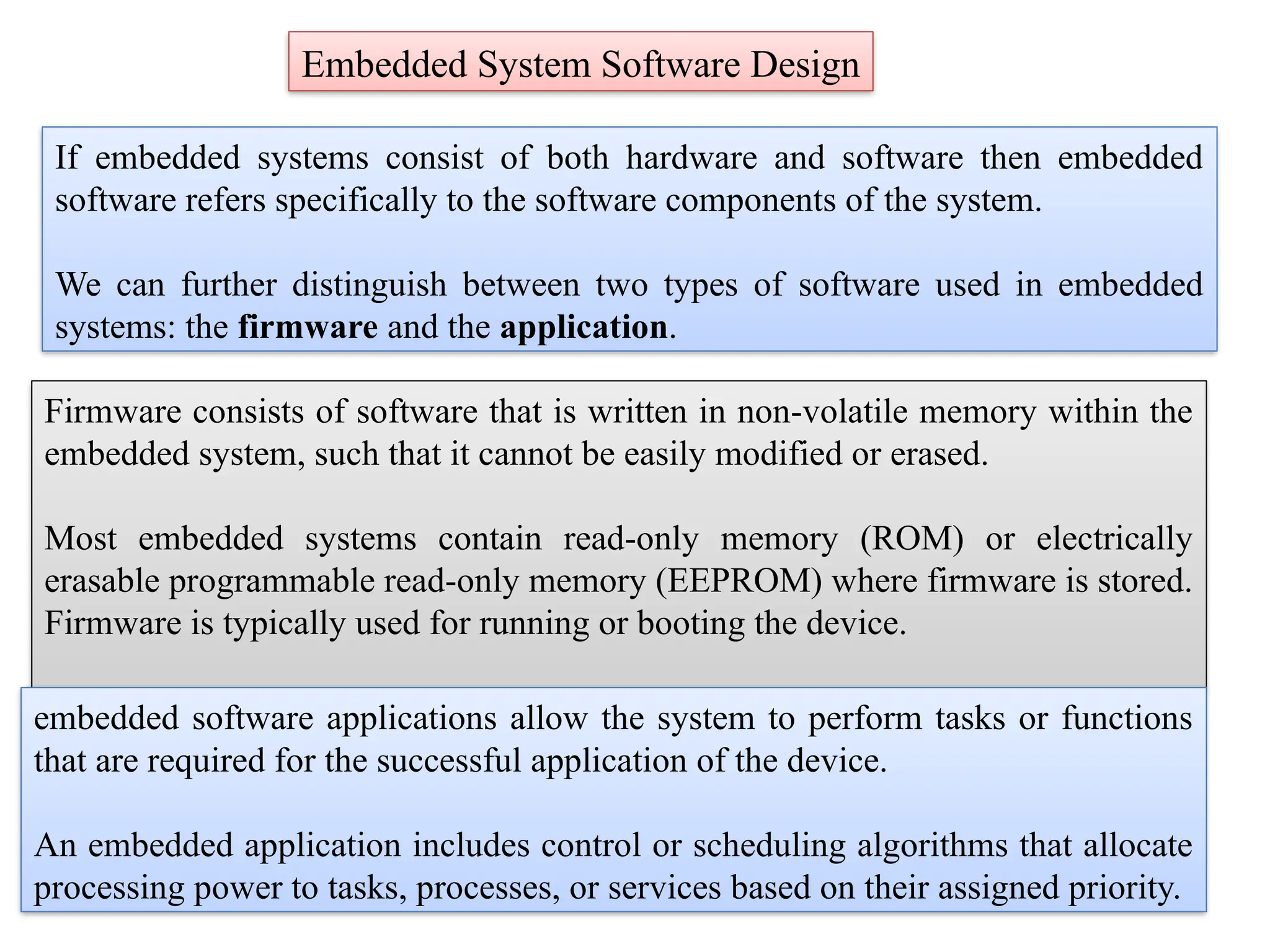
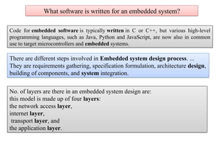
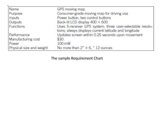
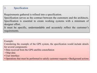
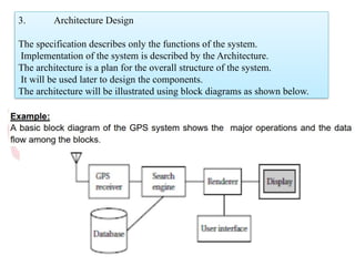
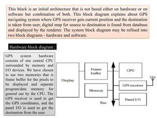
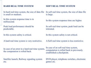
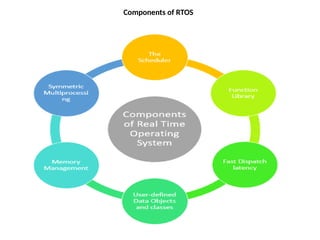
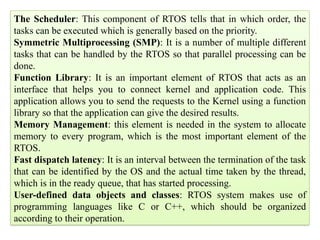
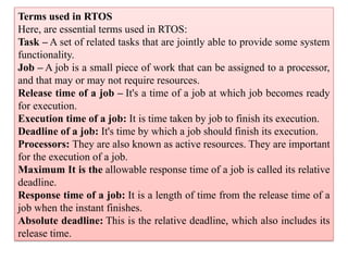
Embedded System Software Design
If embedded systems consist of both hardware and software then embedded
software refers specifically to the software components of the system.
We can further distinguish between two types of software used in embedded
systems: the firmware and the application.
Firmware consists of software that is written in non-volatile memory within the
embedded system, such that it cannot be easily modified or erased.
Most embedded systems contain read-only memory (ROM) or electrically
erasable programmable read-only memory (EEPROM) where firmware is stored.
Firmware is typically used for running or booting the device.
embedded software applications allow the system to perform tasks or functions
that are required for the successful application of the device.
An embedded application includes control or scheduling algorithms that allocate
processing power to tasks, processes, or services based on their assigned priority.
The Embedded System Software Stack
The software stack for an embedded system can vary in
complexity depending on the intended application for the
product.
The most complex systems consist of five or six layers while
simpler systems might include just two or three.
A six-layer software stack for an embedded system might
include the following components:
Embedded software application: The main application is typically coded by engineers to
meet the unique requirements of the project while accounting for power consumption, timing,
and other constraints imposed by the hardware configuration and additional planned software
elements.
Application framework: embedded engineers are enjoying increased access to application
framework modules that provide prepackaged software for embedded systems. An application
framework can include security features, machine-to-machine communication features,
connectivity and location functionality, and other useful features. The presence of available
application frameworks reduces the labor associated with programming embedded software
functions.
Operating environment: includes libraries, runtime, and other services needed to deliver the
core application
Embedded virtualizations: more complex embedded systems may use virtualization to
divide processing power between several different tasks or functions.
Firmware: consists of the software components necessary to run the device, such as boot-
loaders, secure storage, and threading
Hardware: includes the microcontroller or microprocessor and other on-chip peripherals on a
single or multi-layered board
What software is written for an embedded system?
Code for embedded software is typically written in C or C++, but various high-level
programming languages, such as Java, Python and JavaScript, are now also in common
use to target microcontrollers and embedded systems.
There are different steps involved in Embedded system design process. ...
They are requirements gathering, specification formulation, architecture design,
building of components, and system integration.
No. of layers are there in an embedded system design are:
this model is made up of four layers:
the network access layer,
internet layer,
transport layer, and
the application layer.
Design process steps:
There are different steps involved in Embedded system design process.
These steps depend on the design methodology.
Design methodology is important for optimizing performance, and developing
computer aided design tools.
It also makes communication between team members easier.
Figure shows the steps in the design process.
The steps in the design process can be viewed as top down view and bottom up
view.
Top–down view begins with the most abstract description of the system and
concludes with concrete details.
Bottom–up view starts with components to build a system.
Bottom–up design steps are shown in the figure as dashed-line arrows.
We need bottom–up design because we do not have perfect insight into how later
stages of the design process will turn out.
The major goals of the design to be considered are :
● Manufacturing cost;
● Performance (both overall speed and deadlines) and
● Power consumption.
The tasks which need to be performed at each step are the following.
● We must analyze the design at each step to determine how we can meet the
specifications.
● We must then refine the design to add details.
● We must verify the design to ensure that it still meets all system goals, such
as cost, speed, and so on.
1. Requirements
Informal descriptions gathered from the customer are known as requirements.
The requirements are refined into a specification to begin the designing of the
system architecture.
Requirements can be functional or non-functional requirements.
Functional requirements need output as a function of input.
Non-functional requirements includes performance, cost, physical size, weight,
and power consumption.
Performance may be a combination of soft performance metrics such as
approximate time to perform a user-level function and hard deadlines by which
a particular operation must be completed.
Cost includes the manufacturing, nonrecurring engineering(NRE) and other
costs of designing the system.
Physical size and weight are the physical aspects of the final system. These can
vary greatly depending upon the application.
Power consumption can be specified in the requirements stage in terms of
battery life.
The sample Requirement Chart
Example:
Considering the example of the GPS system, the specification would include details
for several components:
• Data received from the GPS satellite constellation
• Map data
• User interface
• Operations that must be performed to satisfy customer requests • Background actions
2. Specification
Requirements gathered is refined into a specification.
Specification serves as the contract between the customers and the architects.
Specification is essential to create working systems with a minimum of
designer effort.
It must be specific, understandable and accurately reflect the customer’s
requirements.
3. Architecture Design
The specification describes only the functions of the system.
Implementation of the system is described by the Architecture.
The architecture is a plan for the overall structure of the system.
It will be used later to design the components.
The architecture will be illustrated using block diagrams as shown below.
This block is an initial architecture that is not based either on hardware or on
software but combination of both. This block diagram explains about GPS
navigating system where GPS receiver gets current position and the destination
is taken from user, digital map for source to destination is found from database
and displayed by the renderer. The system block diagram may be refined into
two block diagrams - hardware and software.
Hardware block diagram :
GPS system hardware
consists of one central CPU
surrounded by memory and
I/O devices. We have chosen
to use two memories that is
frame buffer for the pixels to
be displayed and separate
program/data memory for
general use by the CPU. The
GPS receiver is used to get
the GPS coordinates, and the
panel I/O is used to get the
destination from the user.
Software block diagram :
The software block diagram
closely follows the system
block diagram.
We have added a timer to
control when we read the
buttons on the user interface
and render data onto the
screen.
To have a truly complete
architectural description, we
require more details, such as
where units in the software
block diagram will be
executed in the hardware
block diagram and when the
operations will be performed
in time
To know that our hardware and software architectures in fact meet
constraints on speed, cost, and so on
Estimate the properties of the components in the block diagrams (Example: search
and rendering functions in the moving map system)
• Accurate estimation derives in part from experience, both general design and
particular experience.
• All the non- functional constraints are estimated. If the decisions are based on
bad data, those results will show up only during the final phases of design.
4. Hardware and Software components
The architectural description tells us what components we need.
The component design effort builds those components in conformance to the
architecture and specification.
The components in general includes both hardware and software modules.
Some of the components will be ready-made (example :CPU, memory chips).
5. System integration
After the components are built, they are integrated.
Bugs are typically found during the system integration.
Good planning can help us to find the bugs quickly.
By debugging a few modules at a time, simple bugs can be uncovered.
By fixing the simple bugs early, more complex or obscure bugs can be
uncovered.
System integration is difficult because it usually uncovers problems.
The debugging facilities for embedded systems are usually much more limited
than the desktop systems.
Careful attention is needed to insert appropriate debugging facilities during
design which can help to ease system integration problems.
RTOS are Operating Systems (OS) which act in Real Time (RT). This means that RTOS
have other purposes than general OS or embedded operating systems (EOS).
Embedded Control Systems Design
Real-time tasks have to be completed before a certain deterministic deadline. This requires
that responses to stimulus must always execute within a constant amount of time.
Non real-time systems are considered correct if certain inputs map to certain outputs: the
system (code and hardware) must always do the proper thing given some current state and
input. Real-time systems must achieve the same logical correctness, but must achieve this
logical correctness using constant time algorithms.
An example of a different algorithm to achieve the same logical behavior but within
constant time: Imagine the system must respond to 25 different inputs, and for each of
these inputs, a specific output is generated. A perfectly acceptable non-real-time
implementation is to have a loop that iterates through the list of possible inputs to
determine the proper output. However, such a loop varies in execution time: the input that
happens to be first in the list can be identified much faster than the input that happens to
be 25th in the list. A constant time approach is to use a hash, such that the input itself can
be immediately mapped to the proper output. So a real-time solution would use a hash
instead of a loop to select between many inputs and outputs. In fact, the existence of loops
with non-constant executions certainly indicates that the algorithm is not a real-time
algorithm.
Design of RTOS
Because determinism is often compromised in “high-level” programming language
and OS constructs, real-time designers are confronted more directly than “normal”
application developers with concepts, timing, memory and efficiency at the level
of the OS.
Interrupt servicing
Most modern OS are interrupt-driven. This means that if there are no processes
waiting to be executed, no I/O-devices requesting a service and no users waiting
for an answer, the OS waits till something happens.
The OS is, in principle, not involved in the execution of the code triggered by
the hardware interrupt: this is taken care by the CPU without software
interference.
The OS does have influence on:
connecting a memory address to every interrupt line and
what has to be done immediately after the interrupt has been serviced.
Interrupt Hardware
•Interrupt vector vs non-vectored Interrupt proc.
An Interrupt vector is used in systems with more than one hardware interrupt line
and all these interrupt lines are assembled in an interrupt vector. The interrupt
vector is an array of pointers to the interrupt service routines. In non-vectored
systems when an interrupt occurs, control is transferred to a single routine
that decides what to do with the interrupt. For RT-systems an interrupt vector
is feasible because it lowers the processing time of an interrupt.
•Edge-triggered and level-triggered interrupts
Peripheral devices can transmit their interrupt signals in two different ways. Edge-
triggered interrupts hold risks for a hardware or software loss of the interrupt
and are generally not an efficient solution. For RTOS and EOS where
determinism is an important factor level-triggered interrupts are favourable.
•Interrupt controller
This is a piece of hardware that shields the OS from the electronic details of the
interrupt lines. Some are able to queue interrupts so that none get lost
(determinism!) and some allow assigning priorities to different interrupts.
Examples are a PIC or an APIC. Working with an APIC is beneficial in a
RTOS and EOS.
Interrupt Software
Interrupt Service Routine
This software routine is called when an interrupt occurs on the interrupt line for which
the ISR has been registered in the interrupt vector. The OS does not intervene in the
launching of an ISR, everything is done by the CPU. The context of the current task is
saved on the stack of that task, so each task must get enough stack space to cope with
ISR overhead. An ISR should be as short as possible, because it runs with interrupts
disabled, which prevents other interrupts from being served and tasks from proceeding
(RTOS!). Further processing is a goal of the DSR. Getting data from the ISR to the
DSR should be done in a non-blocking way.
Trap handler/service request
The software interrupts are called by the processor itself, such as in the case of a
register overflow, errors,... They are similar to hardware interrupts, but they run with
hardware interrupts enabled.
Interrupt latency
This is the time between the arrival of the hardware interrupt and the execution of the
corresponding ISR. It is a statistical quantity and it is important to try and get this
number as low as possible and as deterministic as possible in an RTOS. Modern
processors with many levels cache and pipelines are prone to indeterminism
Interrupt priorities
Adds complexity and problems/opportunities known in task scheduling to the
interrupt handling. Not wanted in a RTOS/EOS.
Interrupt nesting
Adds complexity to the code. In a deterministic environment is this not wanted.
Interrupt sharing
Many systems allow different peripheral devices to be linked to the same
hardware interrupt. The ISR servicing this interrupt must then be able to find out
which device generated the interrupt. RTOS do not support this feature; they
only allow one single ISR per IRQ, in order to be as deterministic as possible. So
a RT system designer should be careful when putting interface cards in your
computer because all the ones for which you want to install real-time drivers
must be connected to different interrupt lines !
Issues in Real Time System Design
A Real Time system’s goal is to behave deterministically. Determinism implies
two aspects.
First, if the process asks for CPU, RAM or communication, it should receive it
from the coordination.
Second, if a failure occurs, the system should know what to do.
For a system designer, the most important features of a Real Time application are
scheduling tasks, coping with failure and using available resources.
Scheduling tasks
The system designer has to make sure that (at least a clearly identified, small)
part of the systems processes are scheduled in a predictable way because, even
more than timing, the sequence of processes is an important part of the
application. Scheduling of the processes can for example be done by the
scheduler. It’s essential that the sequence is determined in a deterministic way,
but the scheduler might not suffice here. For example, if two processes have the
same priority, it might be unclear what process will come first. A system
designer should not expect to know the duration of a process, even if this
process gets the full capacity of the processor. Therefore the designer has to
make sure that the scheduling works, even in case of the worst scenario.
Failure
The system should behave reliably during internal or external failure. Possible
failures should be known by the real time system. If the process can’t recover from
a failure, the system should go into a “fail safe/gracefully mode”. If the system
can’t satisfy the task’s timing constraints and therefore also the quality demands, it
should take action by triggering an error. In such a case, it is important to check if
it is possible to remove certain constraints. Internal failure can be a hard- or a
software failure in the system. To cope with software failure, tasks should be
designed to safeguard error conditions. Hardware failure can be processor, board
or link failure. To detect failure the system designer should implement watchdog
systems. If the main program neglects to regularly service the watchdog, it can
trigger a system reset.
Resources and services
In the context of resources and services the term Quality of Service (QoS) is
important. It means that the task must get a fixed amount of “service” per time unit.
This service includes hardware, processing time and communication and is
deterministically known by the system. In contrast to general OS, the hardware
needs to be specifically assigned for every process. In assigning service to tasks, the
programmer should take into account “worst case scenarios”: if various tasks could
be needing a service, then sooner or later they will want it at the same time. Then
the sequence has to maximize the quality of service.
Complexity
There are three classes of system complexity. The first, C1, has centralized
hardware and a centralized state. Everything is determined and external factors
have no influence on the process. Such a system can be designed by one
person. The simplest robots belong to this category. The last, C3, has
decentralized hardware and a decentralized state. The system adapts the
process due to external factors when necessary. Such a system requires more
(approximately 100) designers. An example is the RoboCup team. C2 is an
intermediate level and it has decentralized hardware and a centralized state,
like for example industrial robots do. Such systems require about 10 designers.
The higher the complexity of the interactions (synchronization and
communication) in the system, the harder to make it deterministic because
much more aspects should be taken into account.
Hard real time and Soft real time system
Real time system is defined as a system in which job has deadline, job has to
finished by the deadline (strictly finished). If a result is delayed, huge loss may
happen.
1. Hard Real Time System :
Hard real time is a system whose operation is incorrect whose result is not
produce according to time constraint.
For example,
1. Air Traffic Control 2. Medical System
2. Soft Real Time System
Soft real time system is a system whose operation is degrade if results are not
produce according to the specified timing requirement.
For example
1. Multimedia Transmission and Reception 2. Computer Games
HARD REAL TIME SYSTEM SOFT REAL TIME SYSTEM
In hard real time system, the size of data file
is small or medium.
In soft real time system, the size of data file
is large.
In this system response time is in
millisecond.
In this system response time are higher.
Peak load performance should be
predictable.
In soft real time system, peak load can be
tolerated.
In this system safety is critical. In this system safety is not critical.
A hard real time system is very restrictive. A Soft real time system is less restrictive.
In case of an error in a hard real time system,
the computation is rolled back.
In case of an soft real time system,
computation is rolled back to previously
established a checkpoint.
Satellite launch, Railway signaling system
etc.
DVD player, telephone switches, electronic
games etc.
Components of RTOS
The Scheduler: This component of RTOS tells that in which order, the
tasks can be executed which is generally based on the priority.
Symmetric Multiprocessing (SMP): It is a number of multiple different
tasks that can be handled by the RTOS so that parallel processing can be
done.
Function Library: It is an important element of RTOS that acts as an
interface that helps you to connect kernel and application code. This
application allows you to send the requests to the Kernel using a function
library so that the application can give the desired results.
Memory Management: this element is needed in the system to allocate
memory to every program, which is the most important element of the
RTOS.
Fast dispatch latency: It is an interval between the termination of the task
that can be identified by the OS and the actual time taken by the thread,
which is in the ready queue, that has started processing.
User-defined data objects and classes: RTOS system makes use of
programming languages like C or C++, which should be organized
according to their operation.
Terms used in RTOS
Here, are essential terms used in RTOS:
Task – A set of related tasks that are jointly able to provide some system
functionality.
Job – A job is a small piece of work that can be assigned to a processor,
and that may or may not require resources.
Release time of a job – It's a time of a job at which job becomes ready
for execution.
Execution time of a job: It is time taken by job to finish its execution.
Deadline of a job: It's time by which a job should finish its execution.
Processors: They are also known as active resources. They are important
for the execution of a job.
Maximum It is the allowable response time of a job is called its relative
deadline.
Response time of a job: It is a length of time from the release time of a
job when the instant finishes.
Absolute deadline: This is the relative deadline, which also includes its
release time.
Factors for selecting an RTOS
Here, are essential factors that you need to consider for selecting RTOS:
Performance: Performance is the most important factor required to be
considered while selecting for a RTOS.
Middleware: if there is no middleware support in Real time operating
system, then the issue of time-taken integration of processes occurs.
Error-free: RTOS systems are error-free. Therefore, there is no chance of
getting an error while performing the task.
Embedded system usage: Programs of RTOS are of small size. So we
widely use RTOS for embedded systems.
Maximum Consumption: we can achieve maximum Consumption with
the help of RTOS.
Task shifting: Shifting time of the tasks is very less.
Unique features: A good RTS should be capable, and it has some extra
features like how it operates to execute a command, efficient protection of
the memory of the system, etc.
24/7 performance: RTOS is ideal for those applications which require to
run 24/7.
Disadvantages of RTOS
RTOS system can run minimal tasks together, and it concentrates only on
those applications which contain an error so that it can avoid them.
RTOS is the system that concentrates on a few tasks. Therefore, it is
really hard for these systems to do multi-tasking.
Specific drivers are required for the RTOS so that it can offer fast
response time to interrupt signals, which helps to maintain its speed.
Plenty of resources are used by RTOS, which makes this system
expensive.
The tasks which have a low priority need to wait for a long time as the
RTOS maintains the accuracy of the program, which are under
execution.
Minimum switching of tasks is done in Real time operating systems.
It uses complex algorithms which is difficult to understand.
RTOS uses lot of resources, which sometimes not suitable for the
system.
Task division
Task division and coordination Task division is the splitting up of activities into
separate tasks that are then either assigned.
Task States
♦ Running: This is the task which has control of the CPU. It will normally be the task
which has the highest current priority of the tasks which are ready to run.
♦ Ready: There may be several tasks in this state. The attributes of the task and the
resources required to run it must be available for it to be placed in the 'ready' state.
♦ Waiting: The execution of tasks placed in this state has been suspended because the task
requires some resources which is not available or because the task is waiting for some
signal from the plant, e.g., input from the analog-to-digital converter, or the task is waiting
for the elapse of time.
♦ New: The operating system is aware of the existence of this task, but the task has not
been allocated a priority and a context and has not been included into the list of
schedulable tasks.
Terminated: The operating system has not as yet been made aware of the existence of
this task, although it may be resident in the memory of the computer.
Need of interrupt routines
An interrupt service routine (ISR) is a software routine that hardware invokes
in response to an interrupt.
ISR examines an interrupt and determines how to handle it executes the
handling, and then returns a logical interrupt value.
If no further handling is required the ISR notifies the kernel with a return value.
Interrupts are important because they give the user better control over the
computer.
Without interrupts, a user may have to wait for a given application to have a
higher priority over the CPU to be ran.
This ensures that the CPU will deal with the process immediately.
Interrupt routines in RTOS must follow two rules that do not apply to task
code:
An interrupt routine must not call any RTOS functions that might block,
causing a higher priority task to run may cause the interrupt routine to take a
very long time to complete.
An interrupt controller multiplexes a number of possible interrupt sources on the
platform for presentation to the processor. The interrupt controller in embedded
systems must be configured to prioritize and route interrupts from devices within
the SOC and externally attached devices.
We need to disable interrupts to ensure atomic access. You don't want any other
process to access and potentially modify that variable while you're reading it.
The interrupt management function is controlled by a number of
programmable registers in the NVIC. ... Interrupt masking.
Flexible Interrupt Management. In the Cortex-M0 processor, each
external interrupt can be enabled or disabled and can have its pending status set
or clear by software.
An interrupt is a signal to the processor emitted by hardware or software
indicating an event that needs immediate attention. Whenever
an interrupt occurs, the controller completes the execution of the current
instruction and starts the execution of an Interrupt Service Routine (ISR)
or Interrupt Handler.
Normally, an interrupt service routine proceeds until it is complete without
being interrupted itself in most of the systems.
However, If we have a larger system, where several devices may interrupt the
microprocessor, a priority problem may arise. ...
This "interrupt of an interrupt" is called a nested interrupt.

IV UNITdssssssssssssssssssssssssssssssssdssd.pptx

  • 1.
    Embedded System SoftwareDesign If embedded systems consist of both hardware and software then embedded software refers specifically to the software components of the system. We can further distinguish between two types of software used in embedded systems: the firmware and the application. Firmware consists of software that is written in non-volatile memory within the embedded system, such that it cannot be easily modified or erased. Most embedded systems contain read-only memory (ROM) or electrically erasable programmable read-only memory (EEPROM) where firmware is stored. Firmware is typically used for running or booting the device. embedded software applications allow the system to perform tasks or functions that are required for the successful application of the device. An embedded application includes control or scheduling algorithms that allocate processing power to tasks, processes, or services based on their assigned priority.
  • 2.
    The Embedded SystemSoftware Stack The software stack for an embedded system can vary in complexity depending on the intended application for the product. The most complex systems consist of five or six layers while simpler systems might include just two or three. A six-layer software stack for an embedded system might include the following components:
  • 3.
    Embedded software application:The main application is typically coded by engineers to meet the unique requirements of the project while accounting for power consumption, timing, and other constraints imposed by the hardware configuration and additional planned software elements. Application framework: embedded engineers are enjoying increased access to application framework modules that provide prepackaged software for embedded systems. An application framework can include security features, machine-to-machine communication features, connectivity and location functionality, and other useful features. The presence of available application frameworks reduces the labor associated with programming embedded software functions. Operating environment: includes libraries, runtime, and other services needed to deliver the core application Embedded virtualizations: more complex embedded systems may use virtualization to divide processing power between several different tasks or functions. Firmware: consists of the software components necessary to run the device, such as boot- loaders, secure storage, and threading Hardware: includes the microcontroller or microprocessor and other on-chip peripherals on a single or multi-layered board
  • 4.
    What software iswritten for an embedded system? Code for embedded software is typically written in C or C++, but various high-level programming languages, such as Java, Python and JavaScript, are now also in common use to target microcontrollers and embedded systems. There are different steps involved in Embedded system design process. ... They are requirements gathering, specification formulation, architecture design, building of components, and system integration. No. of layers are there in an embedded system design are: this model is made up of four layers: the network access layer, internet layer, transport layer, and the application layer.
  • 5.
    Design process steps: Thereare different steps involved in Embedded system design process. These steps depend on the design methodology. Design methodology is important for optimizing performance, and developing computer aided design tools. It also makes communication between team members easier. Figure shows the steps in the design process. The steps in the design process can be viewed as top down view and bottom up view. Top–down view begins with the most abstract description of the system and concludes with concrete details. Bottom–up view starts with components to build a system. Bottom–up design steps are shown in the figure as dashed-line arrows. We need bottom–up design because we do not have perfect insight into how later stages of the design process will turn out.
  • 7.
    The major goalsof the design to be considered are : ● Manufacturing cost; ● Performance (both overall speed and deadlines) and ● Power consumption. The tasks which need to be performed at each step are the following. ● We must analyze the design at each step to determine how we can meet the specifications. ● We must then refine the design to add details. ● We must verify the design to ensure that it still meets all system goals, such as cost, speed, and so on.
  • 8.
    1. Requirements Informal descriptionsgathered from the customer are known as requirements. The requirements are refined into a specification to begin the designing of the system architecture. Requirements can be functional or non-functional requirements. Functional requirements need output as a function of input. Non-functional requirements includes performance, cost, physical size, weight, and power consumption. Performance may be a combination of soft performance metrics such as approximate time to perform a user-level function and hard deadlines by which a particular operation must be completed. Cost includes the manufacturing, nonrecurring engineering(NRE) and other costs of designing the system. Physical size and weight are the physical aspects of the final system. These can vary greatly depending upon the application. Power consumption can be specified in the requirements stage in terms of battery life.
  • 9.
  • 10.
    Example: Considering the exampleof the GPS system, the specification would include details for several components: • Data received from the GPS satellite constellation • Map data • User interface • Operations that must be performed to satisfy customer requests • Background actions 2. Specification Requirements gathered is refined into a specification. Specification serves as the contract between the customers and the architects. Specification is essential to create working systems with a minimum of designer effort. It must be specific, understandable and accurately reflect the customer’s requirements.
  • 11.
    3. Architecture Design Thespecification describes only the functions of the system. Implementation of the system is described by the Architecture. The architecture is a plan for the overall structure of the system. It will be used later to design the components. The architecture will be illustrated using block diagrams as shown below.
  • 12.
    This block isan initial architecture that is not based either on hardware or on software but combination of both. This block diagram explains about GPS navigating system where GPS receiver gets current position and the destination is taken from user, digital map for source to destination is found from database and displayed by the renderer. The system block diagram may be refined into two block diagrams - hardware and software. Hardware block diagram : GPS system hardware consists of one central CPU surrounded by memory and I/O devices. We have chosen to use two memories that is frame buffer for the pixels to be displayed and separate program/data memory for general use by the CPU. The GPS receiver is used to get the GPS coordinates, and the panel I/O is used to get the destination from the user.
  • 13.
    Software block diagram: The software block diagram closely follows the system block diagram. We have added a timer to control when we read the buttons on the user interface and render data onto the screen. To have a truly complete architectural description, we require more details, such as where units in the software block diagram will be executed in the hardware block diagram and when the operations will be performed in time
  • 14.
    To know thatour hardware and software architectures in fact meet constraints on speed, cost, and so on Estimate the properties of the components in the block diagrams (Example: search and rendering functions in the moving map system) • Accurate estimation derives in part from experience, both general design and particular experience. • All the non- functional constraints are estimated. If the decisions are based on bad data, those results will show up only during the final phases of design. 4. Hardware and Software components The architectural description tells us what components we need. The component design effort builds those components in conformance to the architecture and specification. The components in general includes both hardware and software modules. Some of the components will be ready-made (example :CPU, memory chips).
  • 15.
    5. System integration Afterthe components are built, they are integrated. Bugs are typically found during the system integration. Good planning can help us to find the bugs quickly. By debugging a few modules at a time, simple bugs can be uncovered. By fixing the simple bugs early, more complex or obscure bugs can be uncovered. System integration is difficult because it usually uncovers problems. The debugging facilities for embedded systems are usually much more limited than the desktop systems. Careful attention is needed to insert appropriate debugging facilities during design which can help to ease system integration problems.
  • 16.
    RTOS are OperatingSystems (OS) which act in Real Time (RT). This means that RTOS have other purposes than general OS or embedded operating systems (EOS). Embedded Control Systems Design Real-time tasks have to be completed before a certain deterministic deadline. This requires that responses to stimulus must always execute within a constant amount of time. Non real-time systems are considered correct if certain inputs map to certain outputs: the system (code and hardware) must always do the proper thing given some current state and input. Real-time systems must achieve the same logical correctness, but must achieve this logical correctness using constant time algorithms. An example of a different algorithm to achieve the same logical behavior but within constant time: Imagine the system must respond to 25 different inputs, and for each of these inputs, a specific output is generated. A perfectly acceptable non-real-time implementation is to have a loop that iterates through the list of possible inputs to determine the proper output. However, such a loop varies in execution time: the input that happens to be first in the list can be identified much faster than the input that happens to be 25th in the list. A constant time approach is to use a hash, such that the input itself can be immediately mapped to the proper output. So a real-time solution would use a hash instead of a loop to select between many inputs and outputs. In fact, the existence of loops with non-constant executions certainly indicates that the algorithm is not a real-time algorithm.
  • 17.
    Design of RTOS Becausedeterminism is often compromised in “high-level” programming language and OS constructs, real-time designers are confronted more directly than “normal” application developers with concepts, timing, memory and efficiency at the level of the OS. Interrupt servicing Most modern OS are interrupt-driven. This means that if there are no processes waiting to be executed, no I/O-devices requesting a service and no users waiting for an answer, the OS waits till something happens. The OS is, in principle, not involved in the execution of the code triggered by the hardware interrupt: this is taken care by the CPU without software interference. The OS does have influence on: connecting a memory address to every interrupt line and what has to be done immediately after the interrupt has been serviced.
  • 18.
    Interrupt Hardware •Interrupt vectorvs non-vectored Interrupt proc. An Interrupt vector is used in systems with more than one hardware interrupt line and all these interrupt lines are assembled in an interrupt vector. The interrupt vector is an array of pointers to the interrupt service routines. In non-vectored systems when an interrupt occurs, control is transferred to a single routine that decides what to do with the interrupt. For RT-systems an interrupt vector is feasible because it lowers the processing time of an interrupt. •Edge-triggered and level-triggered interrupts Peripheral devices can transmit their interrupt signals in two different ways. Edge- triggered interrupts hold risks for a hardware or software loss of the interrupt and are generally not an efficient solution. For RTOS and EOS where determinism is an important factor level-triggered interrupts are favourable. •Interrupt controller This is a piece of hardware that shields the OS from the electronic details of the interrupt lines. Some are able to queue interrupts so that none get lost (determinism!) and some allow assigning priorities to different interrupts. Examples are a PIC or an APIC. Working with an APIC is beneficial in a RTOS and EOS.
  • 19.
    Interrupt Software Interrupt ServiceRoutine This software routine is called when an interrupt occurs on the interrupt line for which the ISR has been registered in the interrupt vector. The OS does not intervene in the launching of an ISR, everything is done by the CPU. The context of the current task is saved on the stack of that task, so each task must get enough stack space to cope with ISR overhead. An ISR should be as short as possible, because it runs with interrupts disabled, which prevents other interrupts from being served and tasks from proceeding (RTOS!). Further processing is a goal of the DSR. Getting data from the ISR to the DSR should be done in a non-blocking way. Trap handler/service request The software interrupts are called by the processor itself, such as in the case of a register overflow, errors,... They are similar to hardware interrupts, but they run with hardware interrupts enabled. Interrupt latency This is the time between the arrival of the hardware interrupt and the execution of the corresponding ISR. It is a statistical quantity and it is important to try and get this number as low as possible and as deterministic as possible in an RTOS. Modern processors with many levels cache and pipelines are prone to indeterminism
  • 20.
    Interrupt priorities Adds complexityand problems/opportunities known in task scheduling to the interrupt handling. Not wanted in a RTOS/EOS. Interrupt nesting Adds complexity to the code. In a deterministic environment is this not wanted. Interrupt sharing Many systems allow different peripheral devices to be linked to the same hardware interrupt. The ISR servicing this interrupt must then be able to find out which device generated the interrupt. RTOS do not support this feature; they only allow one single ISR per IRQ, in order to be as deterministic as possible. So a RT system designer should be careful when putting interface cards in your computer because all the ones for which you want to install real-time drivers must be connected to different interrupt lines !
  • 21.
    Issues in RealTime System Design A Real Time system’s goal is to behave deterministically. Determinism implies two aspects. First, if the process asks for CPU, RAM or communication, it should receive it from the coordination. Second, if a failure occurs, the system should know what to do. For a system designer, the most important features of a Real Time application are scheduling tasks, coping with failure and using available resources. Scheduling tasks The system designer has to make sure that (at least a clearly identified, small) part of the systems processes are scheduled in a predictable way because, even more than timing, the sequence of processes is an important part of the application. Scheduling of the processes can for example be done by the scheduler. It’s essential that the sequence is determined in a deterministic way, but the scheduler might not suffice here. For example, if two processes have the same priority, it might be unclear what process will come first. A system designer should not expect to know the duration of a process, even if this process gets the full capacity of the processor. Therefore the designer has to make sure that the scheduling works, even in case of the worst scenario.
  • 22.
    Failure The system shouldbehave reliably during internal or external failure. Possible failures should be known by the real time system. If the process can’t recover from a failure, the system should go into a “fail safe/gracefully mode”. If the system can’t satisfy the task’s timing constraints and therefore also the quality demands, it should take action by triggering an error. In such a case, it is important to check if it is possible to remove certain constraints. Internal failure can be a hard- or a software failure in the system. To cope with software failure, tasks should be designed to safeguard error conditions. Hardware failure can be processor, board or link failure. To detect failure the system designer should implement watchdog systems. If the main program neglects to regularly service the watchdog, it can trigger a system reset. Resources and services In the context of resources and services the term Quality of Service (QoS) is important. It means that the task must get a fixed amount of “service” per time unit. This service includes hardware, processing time and communication and is deterministically known by the system. In contrast to general OS, the hardware needs to be specifically assigned for every process. In assigning service to tasks, the programmer should take into account “worst case scenarios”: if various tasks could be needing a service, then sooner or later they will want it at the same time. Then the sequence has to maximize the quality of service.
  • 23.
    Complexity There are threeclasses of system complexity. The first, C1, has centralized hardware and a centralized state. Everything is determined and external factors have no influence on the process. Such a system can be designed by one person. The simplest robots belong to this category. The last, C3, has decentralized hardware and a decentralized state. The system adapts the process due to external factors when necessary. Such a system requires more (approximately 100) designers. An example is the RoboCup team. C2 is an intermediate level and it has decentralized hardware and a centralized state, like for example industrial robots do. Such systems require about 10 designers. The higher the complexity of the interactions (synchronization and communication) in the system, the harder to make it deterministic because much more aspects should be taken into account.
  • 24.
    Hard real timeand Soft real time system Real time system is defined as a system in which job has deadline, job has to finished by the deadline (strictly finished). If a result is delayed, huge loss may happen. 1. Hard Real Time System : Hard real time is a system whose operation is incorrect whose result is not produce according to time constraint. For example, 1. Air Traffic Control 2. Medical System 2. Soft Real Time System Soft real time system is a system whose operation is degrade if results are not produce according to the specified timing requirement. For example 1. Multimedia Transmission and Reception 2. Computer Games
  • 25.
    HARD REAL TIMESYSTEM SOFT REAL TIME SYSTEM In hard real time system, the size of data file is small or medium. In soft real time system, the size of data file is large. In this system response time is in millisecond. In this system response time are higher. Peak load performance should be predictable. In soft real time system, peak load can be tolerated. In this system safety is critical. In this system safety is not critical. A hard real time system is very restrictive. A Soft real time system is less restrictive. In case of an error in a hard real time system, the computation is rolled back. In case of an soft real time system, computation is rolled back to previously established a checkpoint. Satellite launch, Railway signaling system etc. DVD player, telephone switches, electronic games etc.
  • 26.
  • 27.
    The Scheduler: Thiscomponent of RTOS tells that in which order, the tasks can be executed which is generally based on the priority. Symmetric Multiprocessing (SMP): It is a number of multiple different tasks that can be handled by the RTOS so that parallel processing can be done. Function Library: It is an important element of RTOS that acts as an interface that helps you to connect kernel and application code. This application allows you to send the requests to the Kernel using a function library so that the application can give the desired results. Memory Management: this element is needed in the system to allocate memory to every program, which is the most important element of the RTOS. Fast dispatch latency: It is an interval between the termination of the task that can be identified by the OS and the actual time taken by the thread, which is in the ready queue, that has started processing. User-defined data objects and classes: RTOS system makes use of programming languages like C or C++, which should be organized according to their operation.
  • 28.
    Terms used inRTOS Here, are essential terms used in RTOS: Task – A set of related tasks that are jointly able to provide some system functionality. Job – A job is a small piece of work that can be assigned to a processor, and that may or may not require resources. Release time of a job – It's a time of a job at which job becomes ready for execution. Execution time of a job: It is time taken by job to finish its execution. Deadline of a job: It's time by which a job should finish its execution. Processors: They are also known as active resources. They are important for the execution of a job. Maximum It is the allowable response time of a job is called its relative deadline. Response time of a job: It is a length of time from the release time of a job when the instant finishes. Absolute deadline: This is the relative deadline, which also includes its release time.
  • 29.
    Factors for selectingan RTOS Here, are essential factors that you need to consider for selecting RTOS: Performance: Performance is the most important factor required to be considered while selecting for a RTOS. Middleware: if there is no middleware support in Real time operating system, then the issue of time-taken integration of processes occurs. Error-free: RTOS systems are error-free. Therefore, there is no chance of getting an error while performing the task. Embedded system usage: Programs of RTOS are of small size. So we widely use RTOS for embedded systems. Maximum Consumption: we can achieve maximum Consumption with the help of RTOS. Task shifting: Shifting time of the tasks is very less. Unique features: A good RTS should be capable, and it has some extra features like how it operates to execute a command, efficient protection of the memory of the system, etc. 24/7 performance: RTOS is ideal for those applications which require to run 24/7.
  • 30.
    Disadvantages of RTOS RTOSsystem can run minimal tasks together, and it concentrates only on those applications which contain an error so that it can avoid them. RTOS is the system that concentrates on a few tasks. Therefore, it is really hard for these systems to do multi-tasking. Specific drivers are required for the RTOS so that it can offer fast response time to interrupt signals, which helps to maintain its speed. Plenty of resources are used by RTOS, which makes this system expensive. The tasks which have a low priority need to wait for a long time as the RTOS maintains the accuracy of the program, which are under execution. Minimum switching of tasks is done in Real time operating systems. It uses complex algorithms which is difficult to understand. RTOS uses lot of resources, which sometimes not suitable for the system.
  • 31.
    Task division Task divisionand coordination Task division is the splitting up of activities into separate tasks that are then either assigned. Task States ♦ Running: This is the task which has control of the CPU. It will normally be the task which has the highest current priority of the tasks which are ready to run. ♦ Ready: There may be several tasks in this state. The attributes of the task and the resources required to run it must be available for it to be placed in the 'ready' state. ♦ Waiting: The execution of tasks placed in this state has been suspended because the task requires some resources which is not available or because the task is waiting for some signal from the plant, e.g., input from the analog-to-digital converter, or the task is waiting for the elapse of time. ♦ New: The operating system is aware of the existence of this task, but the task has not been allocated a priority and a context and has not been included into the list of schedulable tasks. Terminated: The operating system has not as yet been made aware of the existence of this task, although it may be resident in the memory of the computer.
  • 33.
    Need of interruptroutines An interrupt service routine (ISR) is a software routine that hardware invokes in response to an interrupt. ISR examines an interrupt and determines how to handle it executes the handling, and then returns a logical interrupt value. If no further handling is required the ISR notifies the kernel with a return value. Interrupts are important because they give the user better control over the computer. Without interrupts, a user may have to wait for a given application to have a higher priority over the CPU to be ran. This ensures that the CPU will deal with the process immediately. Interrupt routines in RTOS must follow two rules that do not apply to task code: An interrupt routine must not call any RTOS functions that might block, causing a higher priority task to run may cause the interrupt routine to take a very long time to complete.
  • 34.
    An interrupt controllermultiplexes a number of possible interrupt sources on the platform for presentation to the processor. The interrupt controller in embedded systems must be configured to prioritize and route interrupts from devices within the SOC and externally attached devices. We need to disable interrupts to ensure atomic access. You don't want any other process to access and potentially modify that variable while you're reading it. The interrupt management function is controlled by a number of programmable registers in the NVIC. ... Interrupt masking. Flexible Interrupt Management. In the Cortex-M0 processor, each external interrupt can be enabled or disabled and can have its pending status set or clear by software. An interrupt is a signal to the processor emitted by hardware or software indicating an event that needs immediate attention. Whenever an interrupt occurs, the controller completes the execution of the current instruction and starts the execution of an Interrupt Service Routine (ISR) or Interrupt Handler.
  • 35.
    Normally, an interruptservice routine proceeds until it is complete without being interrupted itself in most of the systems. However, If we have a larger system, where several devices may interrupt the microprocessor, a priority problem may arise. ... This "interrupt of an interrupt" is called a nested interrupt.