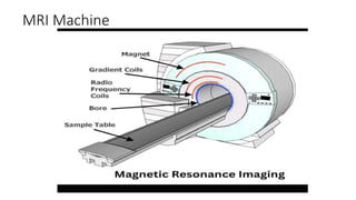
MRI (Magnetic Resonance Imaging) is a non-invasive medical imaging technique that uses strong magnetic fields and radio waves to create detailed images of the body's internal structures
Course Outline:
Definition ofMRI
History of MRI
Safety and patient management in MRI
MRI equipment
The RF cage
MRI parameters
3.
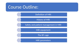
Definition of MRI
MagneticResonance Imaging (MRI)
Introduction:
• Magnetic Resonance Imaging is a phenomenon that involves the use of magnetic
fields, radiofrequency(RF) electromagnetic waves and high speed computers to
produce multiplanar images.
• The Oxford concise medical dictionary defines MRI as a diagnostic technique based on
analysis of the absorption and transmission of high frequency radio waves by the
hydrogen in water molecules and other components of tissues placed in a strong
magnetic field. Using modern high speed computers, this analysis can be used to
‘map out’ the variation in tissue signals in any plane and this produce images of the
tissues in most parts of the body.
4.
Advantages of MRI
•It does not produce or use potentially harmful ionizing radiation i.e
it uses a non ionizing radiation
• No known biological hazards
• It is a non invasive diagnostic technique
• It produces multiplanar imaging i.e images are produced in every
plane.
• It has high soft tissue resolution i.e it produces excellent contrast
between tissues
• It has superior soft tissue characterization. When compared to
other imaging modalities thereby improving diagnostic
information.
• It can used for treatment planning of planning of a wide range of
diseases e.g cancer in Radiotherapy department through
Teleradiology (PACS)
• It demonstrates blood flow imaging better
• It is used to guide interventional radiological procedures
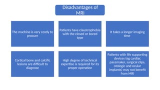
5.
Disadvantages of
MRI
The machineis very costly to
procure
Patients have claustrophobia
with the closed or bored
type
It takes a longer imaging
time
Cortical bone and calcific
lesions are difficult to
diagnose
High degree of technical
expertise is required for its
proper operation
Patients with life supporting
devices (eg cardiac
pacemaker, surgical clips,
otologic and ocular
implants) may not benefit
from MRI
6.
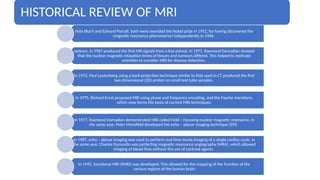
HISTORICAL REVIEW OFMRI
Felix Bloch and Edward Purcell, both were awarded the Nobel prize in 1952, for having discovered the
magnetic resonance phenomenon independently in 1946.
Jackson, in 1967 produced the first MR signals from a live animal. In 1971, Raymond Damadian showed
that the nuclear magnetic relaxation times of tissues and tumours differed. This helped to motivate
scientists to consider MRI for disease detection.
In 1972, Paul Lautenberg using a back projection technique similar to that used in CT produced the first
two dimensional (2D) proton on small test tube samples.
In 1975, Richard Ernst proposed MRI using phase and frequency encoding, and the Fourier transform,
which now forms the basis of current MRI techniques.
In 1977, Raymond Damadian demonstrated MRI called Field – Focusing nuclear magnetic resonance. In
the same year, Peter Mansfield developed the echo – planar imaging technique (EPI).
In 1987, echo – planar imaging was used to perform real time movie imaging of a single cardiac cycle. In
the same year, Charles Dumoulin was perfecting magnetic resonance angiography (MRA), which allowed
imaging of blood flow without the use of contrast agents.
In 1992, functional MRI (fMRI) was developed. This allowed for the mapping of the function of the
various regions of the human brain
7.
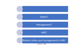
Safety and PatientManagement in MRI
Patient?
Patient’s Bill of Rights
i. medication
ii. emergency service
iii. privacy/confidentiality
iv. medical record
v. involvement in Rx
MRI Request Card
MRI Information leaflet
enwokorie e. 2008
PatientHandling and preparation
Before Examination-
consent form/safety
form and explain
the procedure to
the Patient.
• All metals removed and confirm the answers given on the safety form.
• A line in place on the right hand.(contrast).
• Weight taken if possible.
• Wheelchairs/crutches should not exceed the designated line
• Register the patient and prepare the room for examination.
• Show confidence and be in control of the examination.
Examination Day-
Introduce Yourself,
confirm the
Patient’s ID ( Names,
Address and DOB).
10.
enwokorie e. 2008
PatientHandling
MRI table covered with disposable paper
Reassure the Patient
Give Earplugs
Sedate Paediatric patients/ Psychiatric patients
Have oxygen cylinder in place
Resuscitation Drugs
Suction Machine
Plastic Urine Bowl
Wooden Drip stand
11.
enwokorie e. 2008
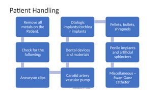
PatientHandling
Remove all
metals on the
Patient.
Check for the
following;
Aneurysm clips
Carotid artery
vascular pump
Dental devices
and materials
Otologic
implants/cochlea
r implants
Pellets, bullets,
shrapnels
Penile implants
and artificial
sphincters
Miscellaneous –
Swan-Ganz
catheter
12.
enwokorie e. 2008
PatientHandling
Psychiatric Patients- doctors must accompany the Pt
Creatinine level checked for patient requiring contrast medium.
For claustrophobic, anxiety and phobic disorders- do the following;
i. Brief the Patient
ii. Allow a company
iii. Calming Music ( headphones)
13.
enwokorie e. 2008
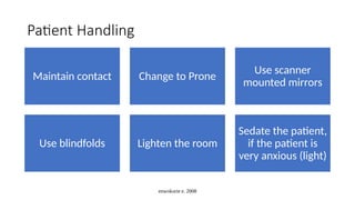
PatientHandling
Maintain contact Change to Prone
Use scanner
mounted mirrors
Use blindfolds Lighten the room
Sedate the patient,
if the patient is
very anxious (light)
14.
enwokorie e. 2008
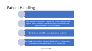
PatientHandling
After the MRI examination, take off the couch roll paper and
replace with a new one; clean the table with a disinfectant.
Then prepare for the next patient.
Drink plenty of fluid for patients that had contrast.
Feedback from patient, give MRI phone number for problem,
reactions and complains within three months, etc.
enwokorie e. 2008
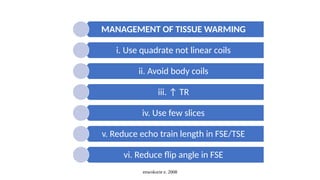
MANAGEMENTOF TISSUE WARMING
i. Use quadrate not linear coils
ii. Avoid body coils
iii. ↑ TR
iv. Use few slices
v. Reduce echo train length in FSE/TSE
vi. Reduce flip angle in FSE
17.
enwokorie e. 2008
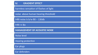
b)GRADIENT EFFECT
harmless sensation of flashes of light
noise above human hearing threshold
MRI noise is b/w 80 – 130db
MRI ∞ Bo
MANAGEMENT OF ACOUSTIC NOISE
Noise level
Hearing protection
Ear plugs
Ear defenders
18.
enwokorie e. 2008
c)STATIC FIELD EFFECTS
Heat
Burns
Death
MANAGEMENT
Remove all ferromagnetic
materials
19.
enwokorie e. 2008
2.USE OF PATIENT CONSENT FORM AND SAFETY QUESTIONNAIRE
Patients’ past medical history
Past surgeries
Cosmetics
Drugs in use
Life saving devices
Allergies
Implants
etc
20.
enwokorie e. 2008
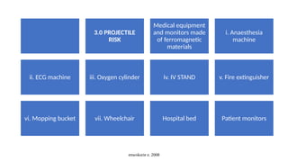
3.0PROJECTILE
RISK
Medical equipment
and monitors made
of ferromagnetic
materials
i. Anaesthesia
machine
ii. ECG machine iii. Oxygen cylinder iv. IV STAND v. Fire extinguisher
vi. Mopping bucket vii. Wheelchair Hospital bed Patient monitors
21.
MRI COMPATIBLE
MEDICAL
EQUIPMENT
Must haveMR
Safe symbol on
them;
i. Patient
transport-Trolleys
& Wheelchairs
ii. Patient
Monitor- ECG,Etc.
iii. Incubator,
iv. IV Stand, v. Stethoscope
enwokorie e. 2008
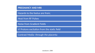
PREGNANCYAND MRI
Hazards to the foetus are from;
Heat from RF Pulses
Noise from Gradient Fields
H+
Protons excitation from the static field
Contrast Media- through the placenta
25.
enwokorie e. 2008
MANAGEMENTOF PREGNANCY AND MRI
↓High Noise sequences – PD
Not for 3T and above
Use SE sequence
↓Flip angle
↓ No. of slices
↓TR
In the first trimester
Use gadodiamide [ Ominiscan]
26.
enwokorie e. 2008
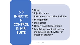
•Drugs
• Injection sites
• Instruments and other facilities
• Management
• Sterilization
• Observe aseptic technique
• Label drugs, contrast, savlon,
methylated spirit, water for
injection properly.
6.0
INFECTIO
N
CONTROL
IN MRI
SUITE
27.
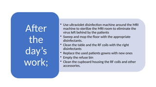
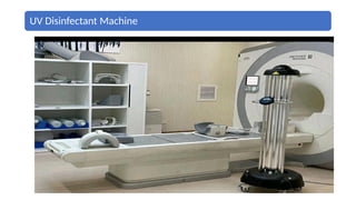
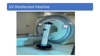
• Use ultravioletdisinfection machine around the MRI
machine to sterilize the MRI room to eliminate the
virus left behind by the patients
• Sweep and mop the floor with the appropriate
disinfectants.
• Clean the table and the RF coils with the right
disinfectants
• Replace the used patients gowns with new ones
• Empty the refuse bin
• Clean the cupboard housing the RF coils and other
accessories.
After
the
day’s
work;
enwokorie e. 2008
7.0CONTRAST
MEDIA USED IN
MRI
Magnevist
[ dimeglumine
gadopntetate]
Dotarem
[ meglumine
gadoterate ]
Ominiscan
[ gadodiamide ]
Optimark
[ gadoversetamid
e ]
Gadovist
[ gadobutrol ]
Chelated Iron
Oxide
ProHance
Hance
Chelated barium
sulphate[ 60-
70w/w]
31.
enwokorie e. 2008
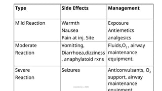
TypeSide Effects Management
Mild Reaction Warmth
Nausea
Pain at inj. Site
Exposure
Antiemetics
analgesics
Moderate
Reaction
Vomitting,
Diarrhoea,dizziness
, anaphylatoid rxns
Fluids,O2 , airway
maintenance
equipment.
Severe
Reaction
Seizures Anticonvulsants, O2
support, airway
maintenance
32.
8.0 CONCLUSION /
RECOMMENDATION
Properinformation on
MRI risks and hazards.
Develop and implement
local policies and rules.
Constant education of
MRI staff and others
from other departments.
enwokorie e. 2008
33.
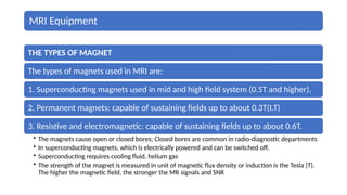
MRI Equipment
THE TYPESOF MAGNET
The types of magnets used in MRI are:
1. Superconducting magnets used in mid and high field system (0.5T and higher).
2. Permanent magnets: capable of sustaining fields up to about 0.3T(I.T)
3. Resistive and electromagnetic: capable of sustaining fields up to about 0.6T.
• The magnets cause open or closed bores; Closed bores are common in radio-diagnostic departments
• In superconducting magnets, which is electrically powered and can be switched off.
• Superconducting requires cooling fluid, helium gas
• The strength of the magnet is measured in unit of magnetic flux density or induction is the Tesla (T).
The higher the magnetic field, the stronger the MR signals and SNR
34.
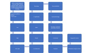
MRI is aRadio-diagnostic
Scan that utilizes strong
magnetic fields, radiowaves
and high speed computers to
produce detailed images of
the body.
It can be classified as
follows;
•Field strength
Low
High
Ultra-high 2. Architecture
Closed
Open
3. Application
Neurology Musculoskeletal
Gastroenterology
Oncology- treatment
planning of tumours
4. End User
Hospitals Ambulatory Surgical centers
Diagnostic Centers
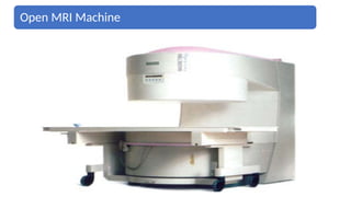
Open MRI systemsare diagnostic systems that
incorporate magnets to take images inside of the
body in an open setting in contrast to the closed
ones.
It has magnetic top and bottom, opens on all four
sides.
It is designed to reduce the risk of claustrophobia
and panic attacks among patients.
This thereby increases the accuracy of the diagnosis.
• Low
• Medium
• High
It can also be classified by field strength;
• Brain, spine
• Breast and cardiac
By Application;
39.
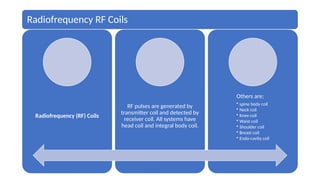
Radiofrequency RF Coils
Radiofrequency(RF) Coils
RF pulses are generated by
transmitter coil and detected by
receiver coil. All systems have
head coil and integral body coil.
Others are;
• spine body coil
• Neck coil
• Knee coil
• Waist coil
• Shoulder coil
• Breast coil
• Endo-cavity coil
40.
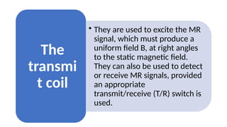
• They areused to excite the MR
signal, which must produce a
uniform field B, at right angles
to the static magnetic field.
They can also be used to detect
or receive MR signals, provided
an appropriate
transmit/receive (T/R) switch is
used.
The
transmi
t coil
41.
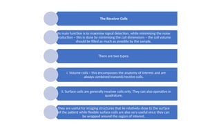
The Receiver Coils
Itsmain function is to maximise signal detection, while minimising the noise
production – this is done by minimising the coil dimensions – the coil volume
should be filled as much as possible by the sample.
There are two types:
i. Volume coils – this encompasses the anatomy of interest and are
always combined transmit/receive coils.
ii. Surface coils are generally receiver coils only. They can also operative in
quadrature.
They are useful for imaging structures that lie relatively close to the surface
of the patient while flexible surface coils are also very useful since they can
be wrapped around the region of interest.
42.
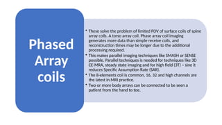
• These solvethe problem of limited FOV of surface coils of spine
array coils. A torso array coil. Phase array coil imaging
generates more data than simple receive coils, and
reconstruction times may be longer due to the additional
processing required.
• This makes parallel imaging techniques like SMASH or SENSE
possible. Parallel techniques is needed for techniques like 3D
CE-MRA, steady state imaging and for high field (3T) – sine it
reduces Specific Assumption Rate (SAR).
• The 8-elements coil is common, 16, 32 and high channels are
the latest in MRI practice.
• Two or more body arrays can be connected to be seen a
patient from the hand to toe.
Phased
Array
coils
43.
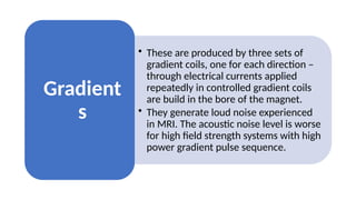
• These areproduced by three sets of
gradient coils, one for each direction –
through electrical currents applied
repeatedly in controlled gradient coils
are build in the bore of the magnet.
• They generate loud noise experienced
in MRI. The acoustic noise level is worse
for high field strength systems with high
power gradient pulse sequence.
Gradient
s
44.
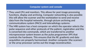
Computer system andconsole
• They used CPU and monitors. This allows for post image-processing
functions, display and archiving. Computer networking is also possible
this will allow the scanner and the workstation to send and receive
data from the hospital networks, through picture archiving and
communications system (PACS) and teleradiology systems:
• The MRI system has a host computer on which the operator selects the
pulse sequence and other protocols of the patient, registration and this
is converted into commands, which are transferred to another
microprocessor system known as the pulse programmer (PP) that
controls the hardware. This ensures that the RF, gradients and data
acquisition are properly harmonised. Another computer (the scanner)
or the array processor carries out the image reconstruction.
45.
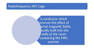
Radiofrequency (RF) Cage
Aconductor which
removes the effect of
external magnetic fields.
Usually built into the
walls of the room
containing the MR1
scanner.
47.
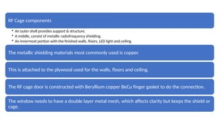
RF Cage components
•An outer shell provides support & structure.
• A middle, consist of metallic radiofrequency shielding.
• An innermost portion with the finished walls, floors, LED light and ceiling.
The metallic shielding materials most commonly used is copper.
This is attached to the plywood used for the walls, floors and ceiling.
The RF cage door is constructed with Beryllium copper BeCu finger gasket to do the connection.
The window needs to have a double layer metal mesh, which affects clarity but keeps the shield or
cage.
SPIN:
Protons (eghydrogen): consist of charged particles
with spin.
Spin is a quantum mechanical, intrinsic property
classified analogue : rotation about an axis.
Charge + non-zero spin= magnetic moment.
Source of (most) MRI signal : protons in water
because of H2+
H
52.
RESONANCE:
Compass needle oscillatesabout
magnetic field before stopping
This oscillations has a well-
defined frequency (resonance
frequency).
MAGNETIZATION:
Excitation and relaxation.
•Excitation: An addition magnetic field
(B1) can defect the compass needle. This
deflection can be maximized by choosing
the new field to be the same as the
resonance frequency.
•Relaxation: After B1 field is removed the
magnetic oscillations decay with a well-
defined time constant.
53.
POLARIZATION:
In theabsence of magnetic field, compass needle
is randomly oriented.
In the presence of magnetic field (e.g. Earth)
needle has a slight tendency to align with the
magnetic field= polarization.
SPIN:
Magnetification = spin
Gravity tilts a spinning object
Because of spin, the axis precesses instead of
tilting.
Spin + gravity =
precession
54.
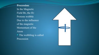
Precession:
In the Magnetic
FieldB0, the H2
Protons wobble
Due to the influence
of the magnetic
Momentum of the
Atom
The wobbling is called
Precession
55.
PROTONS:
Water =80% of Body mass.
H2+ in water molecule.
Magnetic
Field
B0= O Tesla
With no magnetic field, the spin associated with
H2 nuclei are randomly oriented.
H
H
H H
H
H
56.
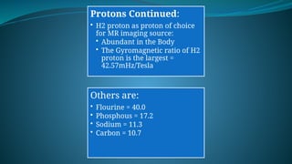
Protons Continued:
• H2proton as proton of choice
for MR imaging source:
• Abundant in the Body
• The Gyromagnetic ratio of H2
proton is the largest =
42.57mHz/Tesla
Others are:
• Flourine = 40.0
• Phosphous = 17.2
• Sodium = 11.3
• Carbon = 10.7
57.
Protons in magneticfield.
Magnetic field
( B0>O Tesla =
M.
With magnetic field, spins along (slightly) with
the field, creating a net magnetic moment. (M)
H
H
H
H H
H
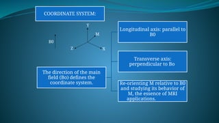
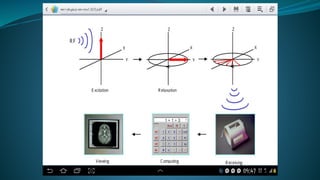
COORDINATE SYSTEM:
The directionof the main
field (Bo) defines the
coordinate system.
Longitudinal axis: parallel to
B0
Transverse axis:
perpendicular to Bo
Re-orienting M relative to B0
and studying its behavior of
M, the essence of MRI
applications.
B0
Z X
Y
M
60.
MAGNETIC RESONANCE:
i. Magnetificationhas characteristics to resonance
frequency
ii. Larmor frequency (w)
iii. For water protons in just above or is in RF range: 64-
128 mHz.
Relaxation: turn off B1 head
i. Relaxation: Excited Magnetification reverts back to
orientation before B1 introduced.
ii. Described by time constant T1 (longitudinal plane).
iii. Described by time constant T2 ( Transverse plane).
Y Y
B0 Z M M
X z x
61.
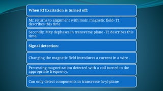
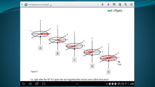
When Rf Excitationis turned off:
Mz returns to alignment with main magnetic field- T1
describes this time.
Secondly, Mxy dephases in transverse plane -T2 describes this
time.
Signal detection:
Changing the magnetic field introduces a current in a wire .
Precessing magnetization detected with a coil turned to the
appropriate frequency.
Can only detect components in transverse (x-y) plane
63.
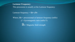
Larmour Frequency:
This precessionis usually at the Larmour frequency.
Larmour frequency = Ɯ0= B
ƴ 0
Where; Ɯ0 = precessional or larmour frequency (mHz)
= Gyromagnetic ratio (mHz/T)
ƴ
B0= Magnetic field strength
64.
Net Magnetization:
Thesum of all tiny magnetic fields of each proton.
The summation of all
The magnetic moments
of the individual hydrogen
Nuclei.
65.
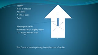
Vector:
It has adirection
And force Z
A sets of axes;
X,y,z
Net magnetization X
(there are always slightly more
H2 nuclei parallel to B0
Y
B0
The Z-axis is always pointing in the direction of the B0
66.
Relaxation Times:
Relaxation isthe process in which spins release the energy
received from a radiofrequency pulse.
Exposure of individual nuclei to RF radiation (B1 field) at
the larmour frequency causes nuclei in question in the lower
energy state to jump into higher energy state.
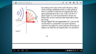
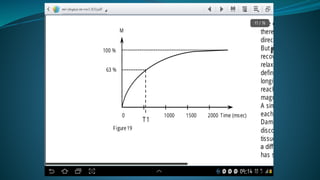
T1 relaxation Time:
Known as spin – lattice relaxation time. It is a measure of
how quickly the NMV recovers to its ground state in the
direction of Bo.
This return is associated with the loss of energy to the
surrounding nuclei(tissue or lattice).
70.
At atime = one T1, the signal will recover to 63%
of its initial value after the RF pulse. Completely
relaxed after 3-5 T1 times.
Higher magnetic fields are associated with
longer T1 times.
T1 weighted images can be obtained using an
inversion recovery sequence or by setting short
TR <750mS (Hundreds) and TE <40mS (tens)
values in conventional spin echo sequences.
While in gradient echo sequences, T1 weighted
images can be obtained by using flip angle >50ᴼ
and setting the TE < 15mS.
71.
T2 Relaxation Time:
This refers to the progressive dephasing of
spining dipoles following the 90ᴼ Pulse as seen in
a spin echo sequence due to tissue particular
characteristics.
It is known as spin – spin relaxation
It affects the rate of movement of protons
especially in H2O.
In phase
Out of phase
75.
The transferof energy between the poles
increases as the frequency of the variation of the
local magnetic field approaches the larmour
frequency.
This is related to the rate of rotation and
translation of water molecule or adjacent
dipoles. The strength of the local field is
increased by the dipole- dipole interaction.
Which is dependent on the proximity of the
adjacent dipoles.
76.
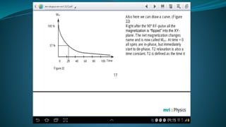
T2 Weighted Images:
Water ; T2 is long ; 3-4seconds
Macromolecules and tissues; the relaxation rate is
faster; T2 is shorter; due to slow motion of protons
in macromolecules.
The slow motion is closer to the larmour frequency.
CSF; T1 = 1.9sec
T2 = 0.25 sec
Brain White matter; T1 = 0.5sec
T2 = 0.07 sec
The shorter T2 causes bones, calculi and teeth to
appear dark. This is as a result of little water in
them (low proton density)
77.
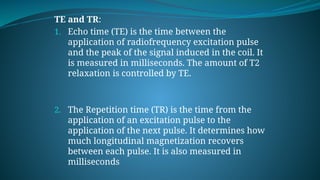
TE and TR:
1.Echo time (TE) is the time between the
application of radiofrequency excitation pulse
and the peak of the signal induced in the coil. It
is measured in milliseconds. The amount of T2
relaxation is controlled by TE.
2. The Repetition time (TR) is the time from the
application of an excitation pulse to the
application of the next pulse. It determines how
much longitudinal magnetization recovers
between each pulse. It is also measured in
milliseconds
78.
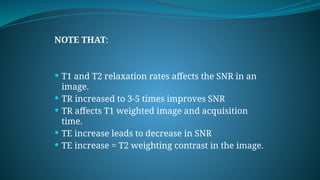
NOTE THAT:
T1and T2 relaxation rates affects the SNR in an
image.
TR increased to 3-5 times improves SNR
TR affects T1 weighted image and acquisition
time.
TE increase leads to decrease in SNR
TE increase = T2 weighting contrast in the image.
79.
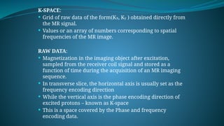
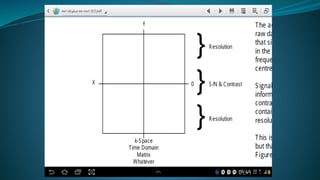
K-SPACE:
MR hascontrol over how the Data are acquired
and how they can be manipulated to influence
the reconstructed image,
Modifying parameters affecting spatial and
temporal resolution, the field of view, the
contrast, the speed of the acquisition and the
influence of various types of artefacts.
This is possible due to k-space; the data matrix
obtained directly from magnetic resonance
scanner.
80.
K-SPACE:
Grid ofraw data of the form(Kx, Ky ) obtained directly from
the MR signal.
Values or an array of numbers corresponding to spatial
frequencies of the MR image.
RAW DATA:
Magnetization in the imaging object after excitation,
sampled from the receiver coil signal and stored as a
function of time during the acquisition of an MR imaging
sequence.
In transverse slice, the horizontal axis is usually set as the
frequency encoding direction
While the vertical axis is the phase encoding direction of
excited protons – known as K-space
This is a space covered by the Phase and frequency
encoding data.
81.
K-Space:
Abstract concept
Data matrix
Contains raw MRI data
The data is subjected to mathematical function
or formula called a Transform to generate the
final image.
A discrete fourier or fast fourier transform is
generally used.
A slice is a K-space acquired in real time.
84.
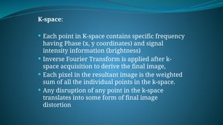
K-space:
Each pointin K-space contains specific frequency
having Phase (x, y coordinates) and signal
intensity information (brightness)
Inverse Fourier Transform is applied after k-
space acquisition to derive the final image,
Each pixel in the resultant image is the weighted
sum of all the individual points in the k-space.
Any disruption of any point in the k-space
translates into some form of final image
distortion
85.
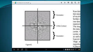
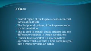
K-Space:
Central regionof the k-space encodes contrast
information (SNR).
The Peripheral regions of the k-space encode
spatial resolution.
This is used to explain image artifacts and the
different techniques in image acquisitions
Fourier Transform(FT) is a mathematical
operation which converts a time domain signal
into a frequency domain signal
86.
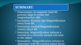
SUMMARY:
• Polarization: inmagnetic field B0
protons align to create net
magnetization. (M)
• Excitation: Rf pulse tips Magnetification
away from B0.
• Precession excited Magnetification
rotates about B0.
• Detection: Magnetification induces a
current in a correctly turned coil close
to the object
• Relaxation : Magnetification returns to
alignment with B0 causing signal decay


![enwokorie e. 2008
MANAGEMENT OF PREGNANCY AND MRI
↓High Noise sequences – PD
Not for 3T and above
Use SE sequence
↓Flip angle
↓ No. of slices
↓TR
In the first trimester
Use gadodiamide [ Ominiscan]](https://image.slidesharecdn.com/mrirad422-250725005514-cbc873d4/85/Introduction-to-Magnetic-Resonance-Imaging-25-320.jpg)
![enwokorie e. 2008
7.0 CONTRAST
MEDIA USED IN
MRI
Magnevist
[ dimeglumine
gadopntetate]
Dotarem
[ meglumine
gadoterate ]
Ominiscan
[ gadodiamide ]
Optimark
[ gadoversetamid
e ]
Gadovist
[ gadobutrol ]
Chelated Iron
Oxide
ProHance
Hance
Chelated barium
sulphate[ 60-
70w/w]](https://image.slidesharecdn.com/mrirad422-250725005514-cbc873d4/85/Introduction-to-Magnetic-Resonance-Imaging-30-320.jpg)


![MAGNETIC_RESONANCE.._IMAGING[MRI][1].pptx](https://cdn.slidesharecdn.com/ss_thumbnails/magneticresonanceimagingmri1-240903182728-4f857936-thumbnail.jpg?width=640&height=640&fit=bounds)


![CTEV [ clubfoot] DR ARUN LAL ,DR MOHAMED ASHRAF travancore medical college k...](https://cdn.slidesharecdn.com/ss_thumbnails/ctevclubfootdrarunlaldrmohamedashraftravancoremedicalcollegekollamkeralaindia-260208063247-18fc466c-thumbnail.jpg?width=640&height=640&fit=bounds)


