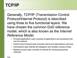
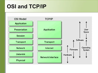
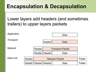
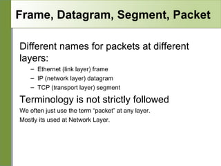
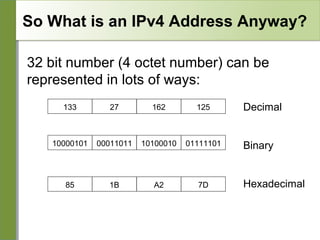
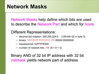
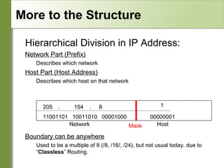
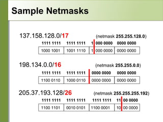
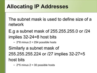
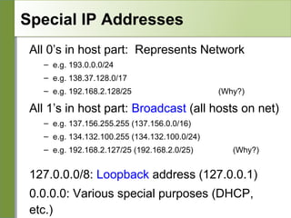
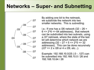
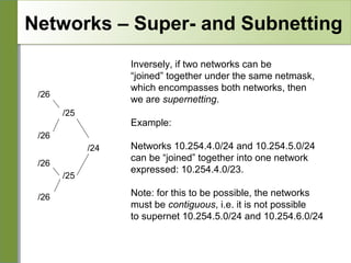
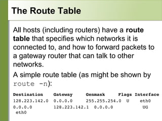
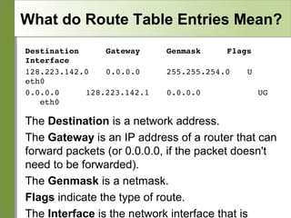
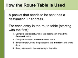
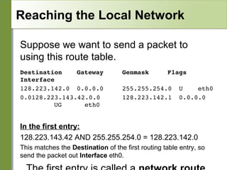
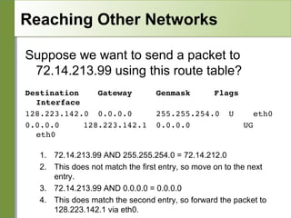
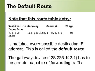
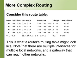
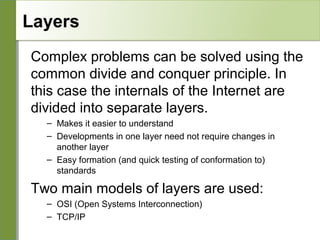
Networking is divided into layers for modularity and standardization. The OSI model has 7 layers, while TCP/IP typically uses a 4 layer model. Each layer encapsulates the packet from the previous layer, adding a header. Packets are called frames, datagrams or segments depending on the layer. IP addresses are 32-bit numbers that specify networks and hosts. Subnet masks define the network and host portions. Routers use route tables to determine the next hop for packets based on the destination address.
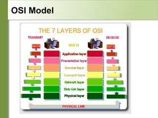
![OSI
Conceptual model composed of seven layers,
developed by the International Organization
for Standardization (ISO) in 1984.
Layer 7 – Application (servers and clients etc web browsers, httpd)
Layer 6 – Presentation (file formats e.g pdf, ASCII, jpeg etc)
Layer 5 – Session (conversation initialisation, termination, )
Layer 4 – Transport (inter host comm – error correction, QOS)
Layer 3 – Network (routing – path determination, IP[x] addresses etc)
Layer 2 – Data link (switching – media acces, MAC addresses etc)
Layer 1 – Physical (signalling – representation of binary digits)
Acronym: All People Seem To Need Data
Processing](https://image.slidesharecdn.com/intro-tcp-ip-140129170225-phpapp01/85/Intro-tcp-ip-4-320.jpg)