Download to read offline


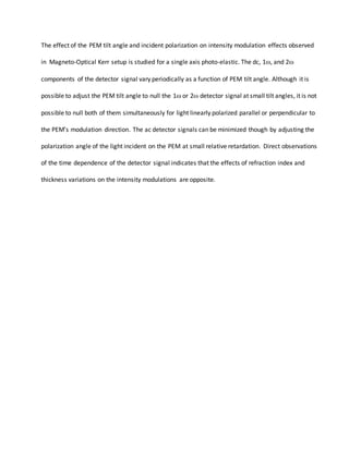
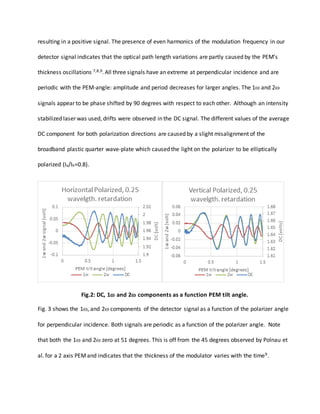
![Fig. 3: DC, 1, and 2 components of the detector signal as a function of the polarizer angle (-90
and 90 degrees are vertically polarized).
IV. DATA ANALYSIS
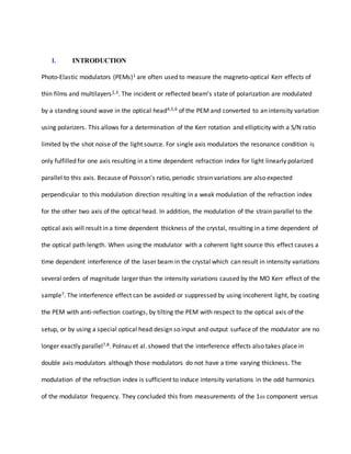
We used the approach of Hecht10 to derive an expression for the transmission of the PEM that
includes the interference effect.
)(2
2
2
)(2
0
)(2
)12(
2
1
1
tnd
i
ga
tnd
i
agga
k
tnd
ki
k
gagaagi
ii
t
er
e
tterttE
EE
E
T
[1]
Where tag (tga) is the amplitude transmission coefficient for the air-glass (glass-air) interface, rga is
the amplitude reflection coefficients for the glass-air interrface, is the laser wavelength, t is the
time, and nd(t) the optical path length upon one pass of the laser beam through the optical head.
Since both the refraction index and the thickness of the optical head are modulated, the optical
path length is described by the product of two periodic functions:](https://image.slidesharecdn.com/eb9bd067-e9fe-44db-9c77-54497cb92ed3-161025204506/85/InterferenceEffectInPEMV13-7-320.jpg)
![
tbatnddndntdn
tnddndndntddtnntnd
oooo
oooooo
sin)sin()(2cos
2
1
)sin()(
2
1
sinsin)(
[2]
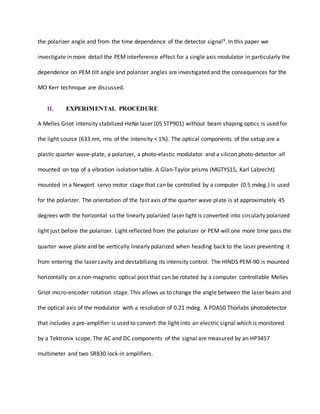
Where no is the refraction index of the optical head, i.e. fused silica (1.4569 at 633 nm), is the
modulation frequency of the PEM, do is the thickness of the optical head (6.35 mm), n the
amplitude of the refraction index variations induced by the periodic strain, and d the modulation
of the thickness of the optical head. For a single axis modulator 1
2
1
dn and can the 2nd dc
term and the 2wt term in equation (2) can be neglected. The transmitted intensity can be found
from squaring equation (1) followed by a Taylor approximation, substituting equation (2), and then
rewriting the cos(sin) and sin(sin) terms as Fourier series of Bessel functions Jn:
2
212
4
)2cos()cos(2sin)()sin(2)cos(
2
1
io EHHtbJatbJabJa
r
r
I
[3]
Where HH indicate the higher harmonics terms beyond 2t. Note that although we do not see a
cos(2t) term in equation [2], the intensity shows a 2t component originating from the sin(sin)
term of the denominator of equation (1). Strictly speaking equation (3) is only valid for
perpendicular incident as equation (2) only provides the optical path length at perpendicular
incident. For non zero tilt angles, nd(t) can be approximated by replacing a and b in equations (2)
and (3) by a/cos(no) and b/cos(no), where is the polarizer tilt angle. This approximation
ignores the effect of the tilt angle on the effective refraction index. As a>>1, all three terms will
oscillate as a function of the tilt angle. Ignoring the effect of the tilt on b and using a small angle](https://image.slidesharecdn.com/eb9bd067-e9fe-44db-9c77-54497cb92ed3-161025204506/85/InterferenceEffectInPEMV13-8-320.jpg)
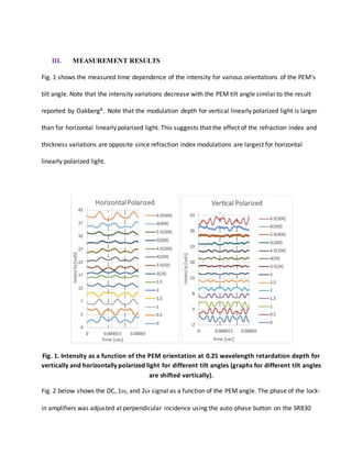
![approximation for cos(/no) we find for the tilt angle dependence of the intensity ( up to the 2nd
harmonic):
2
12
2
22
2
2
4
sin)(
2
sin2)2cos(2
2
cos
2
1
i
o
o
o
EtbJ
n
atbJbJ
n
a
r
r
I
[4]
The DC and 2t term will oscillate in phase as they both have a cosine dependence on f, and the 1
term will oscillate 90 degrees out of phase in agreement with our observations reported in Fig. 2.
V. CONCLUSIONS
Intensity variation caused by the PEM interference effect can be minimized at small PEM tilt angles
by adjusting the PEM tilt angle although not simultaneously for the 1 and 2 components. For a
0.25 wave retardation depth, the 1 and 2 signal can be minimized simultaneously by adjusting
the polarizer angle. By applying both adjustment one can avoid the large fluctuations caused by the
PEM interference effect at small PEM angles.
ACKNOWLEDGEMENT
This work was supported by a DOD grant (HBCU/MI grant W911NF-15-1-0394). MT
acknowledges financial support from the Graduate College of Texas State University.](https://image.slidesharecdn.com/eb9bd067-e9fe-44db-9c77-54497cb92ed3-161025204506/85/InterferenceEffectInPEMV13-9-320.jpg)


The document studies how the tilt angle and incident polarization of light affects intensity modulation in a photo-elastic modulator (PEM) setup. It finds that the dc, 1ω, and 2ω detector signal components vary periodically with PEM tilt angle. While adjusting the tilt angle can null the 1ω or 2ω signals individually at small angles, it is not possible to null both simultaneously for light polarized parallel or perpendicular to the PEM's modulation direction. Minimizing the ac signals requires adjusting both the tilt angle and incident polarization. Analysis shows the intensity variations arise from interference of light reflecting within the PEM due to variations in its refractive index and thickness during modulation.


