Detailed informative notes on "Interference" including Path difference, phase difference, coherent sources, methods to obtain coherent sources, sustained interference, interference due to thin films, interference due to wedge shaped films, Newton's rings, Applications
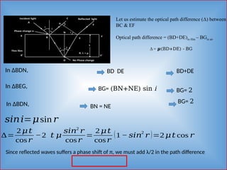
![II. Determination of Refractive Index () of a Liquid
Diameter of nth
order dark fringe in air film is
(3)
Diameter of nth
order dark fringe in liquid film is
(4)
Taking the ration of equation (3) and (4), we have
𝝁=
[ 𝐷𝑛
2
]𝑎𝑖𝑟
[𝐷𝑛
2
]𝑙𝑖𝑞𝑢𝑖𝑑](https://image.slidesharecdn.com/interference-dr-250415042633-9b3b87b2/85/Interference-By-Dr-Priyanka-Nayak-pptx-28-320.jpg)