Chapter 9 focuses on maintaining and troubleshooting network security implementations, outlining key components such as management, control, and data planes. It emphasizes the importance of understanding security features that can impact troubleshooting processes, including AAA protocols for secure management access. The chapter also discusses common issues with TACACS+ and RADIUS authentication and how to troubleshoot them effectively.


![Chapter 9
31
© 2007 – 2010, Cisco Systems, Inc. All rights reserved. Cisco Public
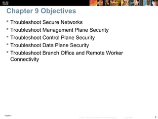
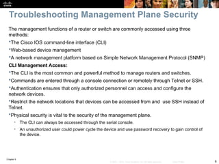
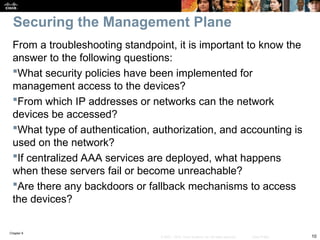
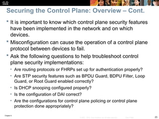
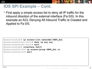
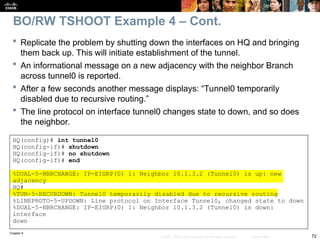
Router(config)# ip inspect audit-trail
Router(config)#
%FW-6-SESS_AUDIT_TRAIL_START: Start http session: initiator
(192.168.0.2:10032) –– responder (10.0.0.10:80)
Router# debug ip inspect
Object-creation INSPECT Object Creations debugging is on
Router#
CBAC* OBJ_CREATE: Pak 6621F7A0 sis 66E4E154 initiator_addr
(192.168.0.2:10032) responder_addr (10.0.0.10:80) initiator_alt_addr
(192.168.0.2:10032) responder_alt_addr (10.0.0.2:80)
CBAC OBJ-CREATE: sid 66E684B0 acl DENY_ALL Prot: tcp
Src 10.0.0.10 Port [80:80]
Dst 192.168.0.2 Port [10032:10032]
CBAC OBJ_CREATE: create host entry 66E568DC addr 10.0.0.10 bucket 8
(vrf 0:0) insp_cb 0x66B61C0C
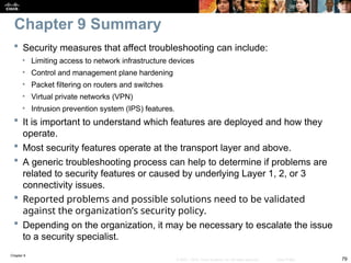
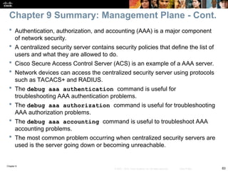
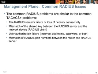
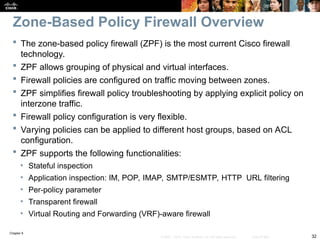
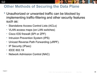
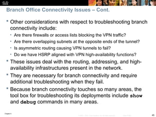
An audit trail can be enabled to generate syslog messages for each SPI session
creation and deletion using the ip inspect audit-trail command. The output of
the debug ip inspect command provides greater detail.
IOS SPI Example – Cont.](https://image.slidesharecdn.com/ch09-241208162805-dd81bc04/85/Installation-et-configuration-de-systeme-31-320.jpg)

![Chapter 9
49
© 2007 – 2010, Cisco Systems, Inc. All rights reserved. Cisco Public
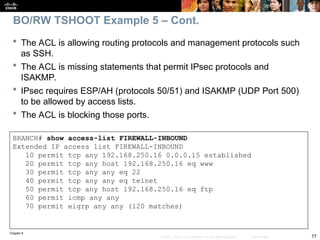
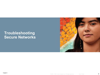
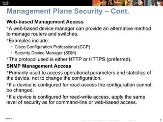
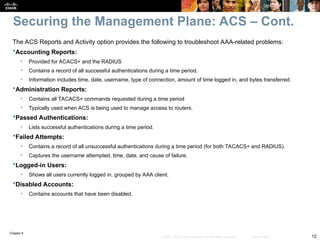
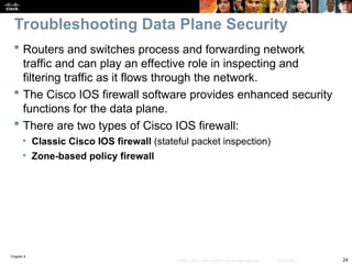
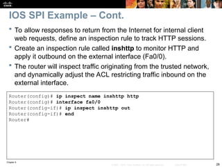
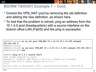
BRANCH# sh ip nat statistics
Total active translations: 1 (1 static, 0 dynamic, 0 extended)
Outside interfaces:
Serial0/0/0
Inside interfaces:
FastEthernet0/0
Hits: 0 Misses: 0
CEF Translated packets: 0, CEF Punted packets: 0
Expired translations: 0
Dynamic mappings:
–– Inside Source
[Id: 1] access-list 150 pool PUBLIC refcount 0
pool PUBLIC: netmask 255.255.255.0
start 172.16.1.100 end 172.16.1.200
type generic, total addresses 101, allocated 0 (0%), misses 0
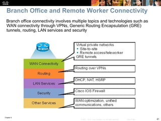
[Id: 2] access-list VPN pool VPN_NAT refcount 0
start 10.1.10.10 end 10.1.10.200
type generic, total addresses 191, allocated 0 (0%), misses 0
Queued Packets: 0
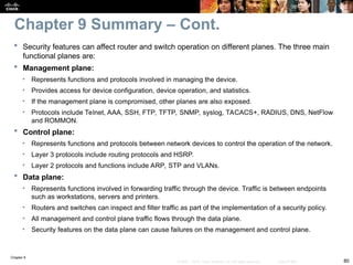
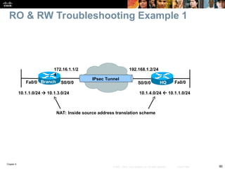
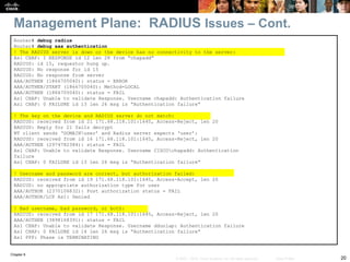
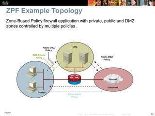
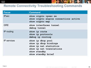
On the Branch router, use the show ip nat statistics command to
display NAT information.
BO/RW TSHOOT Example 1 – Cont.](https://image.slidesharecdn.com/ch09-241208162805-dd81bc04/85/Installation-et-configuration-de-systeme-49-320.jpg)
![Chapter 9
57
© 2007 – 2010, Cisco Systems, Inc. All rights reserved. Cisco Public
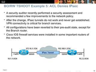
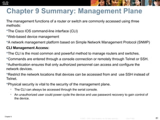
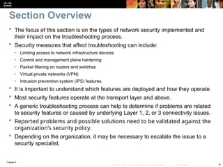
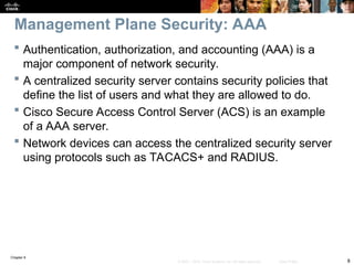
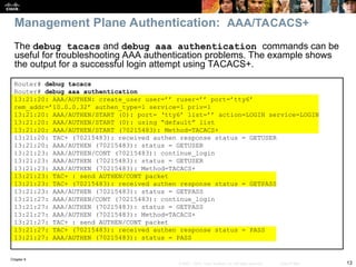
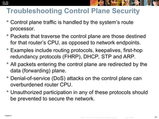
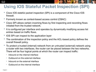
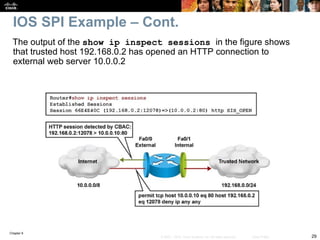
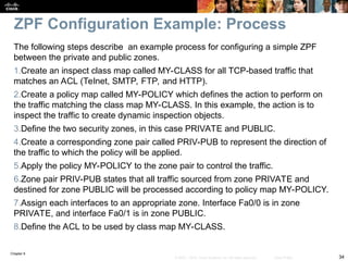
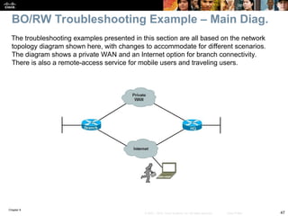
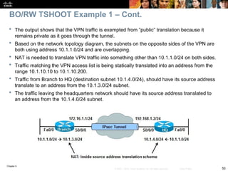
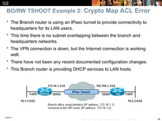
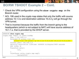
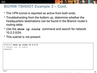
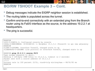
Check to see if there is a routing problem using the show
ip route command.
The output show what is expected for a small branch office:
a static default pointing to a next hop on the WAN interface.
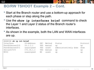
BRANCH# show ip route
<output omitted>
Gateway of last resort is 172.16.1.2 to network 0.0.0.0
172.16.0.0 255.255.255.0 is subnetted, 1 subnets
C 172.16.1.0 is directly connected, Serial0/0/0
10.0.0.0 255.255.255.0 is subnetted, 3 subnets
C 10.1.3.0 is directly connected, Loopback0
C 10.1.1.0 is directly connected, FastEthernet0/0
C 10.251.1.0 is directly connected, Loopback1
S* 0.0.0.0 0.0.0.0 [1/0] via 172.16.1.2
BO/RW TSHOOT Example 2 – Cont.](https://image.slidesharecdn.com/ch09-241208162805-dd81bc04/85/Installation-et-configuration-de-systeme-57-320.jpg)
![Chapter 9
58
© 2007 – 2010, Cisco Systems, Inc. All rights reserved. Cisco Public
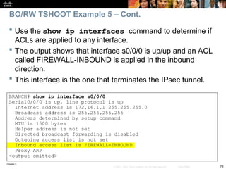
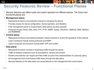
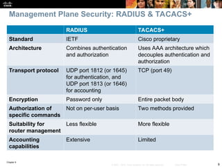
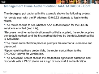
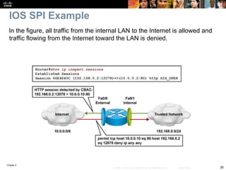
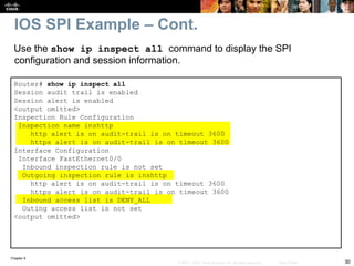
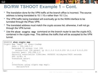
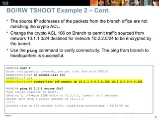
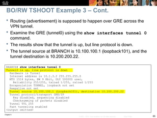
BRANCH# show ip nat statistics
Total active translations: 1 (1 static, 0 dynamic, 0 extended)
Outside interfaces:
Serial0/0/0
Inside interfaces:
FastEthernet0/0
Hits: 60 Misses: 0
CEF Translated packets: 10, CEF Punted packets: 30
Expired translations: 7
Dynamic mappings:
–– Inside Source
[Id: 3] access-list 107 pool PUBLIC refcount 0
pool PUBLIC: netmask 255.255.255.0
start 172.16.1.100 end 172.16.1.200
type generic, total addresses 101, allocated 0 (0%), misses 0
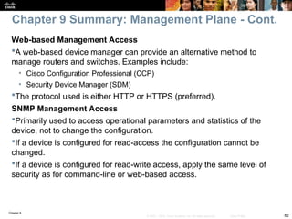
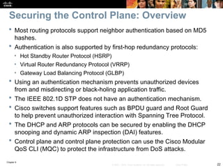
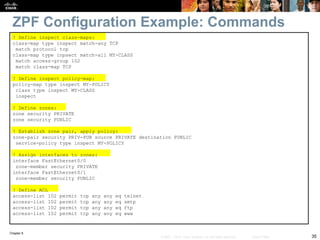
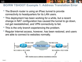
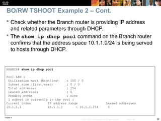
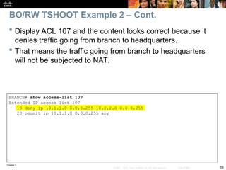
Next, check NAT with the show ip nat statistics command.
The output reveals that traffic matching ACL 107 will be translated.
BO/RW TSHOOT Example 2 – Cont.](https://image.slidesharecdn.com/ch09-241208162805-dd81bc04/85/Installation-et-configuration-de-systeme-58-320.jpg)
![Chapter 9
74
© 2007 – 2010, Cisco Systems, Inc. All rights reserved. Cisco Public
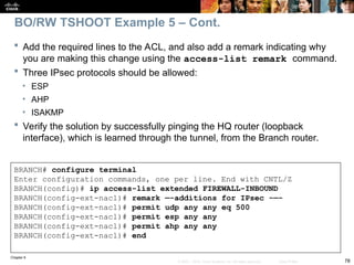
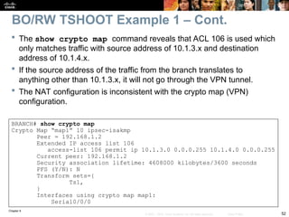
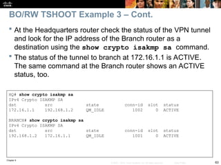
HQ# show ip route
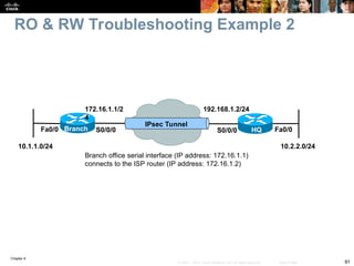
<output omitted>
Gateway of last resort is 192.168.1.1 to network 0.0.0.0
10.0.0.0 255.0.0.0 is variably subnetted, 8 subnets, 2 masks
C 10.1.3.0 255.255.255.0 is directly connected, Tunnel0
C 10.200.200.0 255.255.255.0 is directly connected, Loopback101
D 10.100.100.0 255.255.255.0
[90/297372416] via 10.1.3.2, 00:00:07, Tunnel0
C 10.2.2.0 255.255.255.0 is directly connected, FastEthernet0/0
D 10.1.1.0 255.255.255.0 [90/297372416] via 10.1.3.2, 00:00:07, Tunnel0
S 10.100.100.1 255.255.255.255 [1/0] via 172.16.1.1
C 192.168.1.0 255.255.255.0 is directly connected, serial0/0/0
S* 0.0.0.0 0.0.0.0 [1/0] via 192.168.1.1
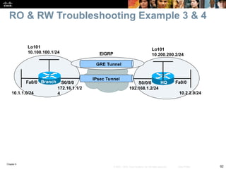
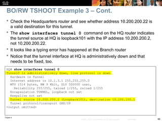
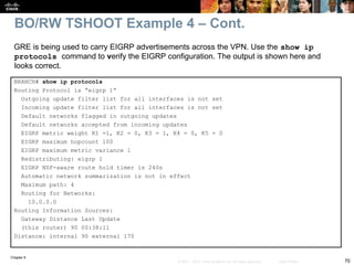
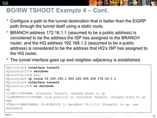
A display of the HQ routing table using the show ip route command
includes three paths to the tunnel0 destination (10.100.100.1):
The gateway of last resort (0.0.0.0/0) through 192.168.1.1 (the ISP’s IP address
at HQ – not shown in the topology).
The one is using the EIGRP route 10.100.100.0/24 through the tunnel0
interface.
The one is using the static route entered to 10.100.100.1/32 through 172.16.1.1.
This is the most specific one and will be used to reach the tunnel end.
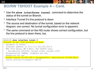
BO/RW TSHOOT Example 4 – Cont.](https://image.slidesharecdn.com/ch09-241208162805-dd81bc04/85/Installation-et-configuration-de-systeme-74-320.jpg)