Download to read offline


![7
(11.2015)
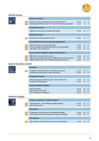
Inductive sensors
Position sensors
Dimensions
Example IFS290
Example IFS285
Example IGS280
Example IFS277
Example IIS269
Example IIS268
Sensing range
[mm]
Current rating
[mA]
Switching
frequency
[Hz]
Order
number
M12 connector · 3 wire DC PNP · Output function normally open
45 4 1002000 IFS289M12
M12
M12
M12
M18
M18
45 10 1002000 IFS290
60 4 1002000 IFS285
60 10
Installation
flush
non-flush
flush
non-flush 1002000 IFS286
45 8 1002000 IGS279
45 15 1002000 IGS280
flush
non-flush
M18
M18
60 8 1002000 IGS277
60 15 1002000 IGS278
flush
non-flush
M30
M30
45 15 1002000 IIS269
60 15 1002000 IIS267
flush
flush
M30 60 30 1002000 IIS268non-flush
Type Total length
[mm]
Operating voltage [V DC] 10...30
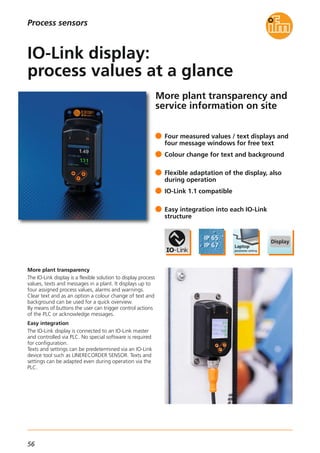
Reverse polarity protection •
Short-circuit protection •
Overload protection •
Protection rating
IP 65 / IP 66 / IP 67 /
IP 68 / IP 69K
Protection class III
Ambient temperature [°C] -40...85
Output status indication [LED] yellow (4 x 90°)
Further technical data
Connection technology
Type Version Order
number
Socket, M12,
2 m black, PUR cable
EVC001
Socket, M12,
5 m black, PUR cable
EVC002
Socket, M12,
2 m black, PUR cable
EVC004
Socket, M12,
5 m black, PUR cable
EVC005
For further technical details please visit: www.ifm.com
Housing materials
brass
plated with white bronze,
sensing face
LCP
34
25
M12x1
17
4
M12x1
45
LED 4 x 90°
5
49
45
M12x1
M12x1
60
LED 4 x 90° 17
4
LED 4 x 90°
45
34
30
1015
M12x1
4
M18x1
24
M18x1
M12x1
45
49
60
LED 4 x 90° 24
4
45
M30x1,5
49
60
M12x1
LED 4 x 90° 5
36
45
49
60
22,5
M30x1,5
M12x1
LED 4 x 90°
5
36](https://image.slidesharecdn.com/ifm-innovations-topproducts-2015-2016-gb-160202102146/85/Innovations-2015-2016-8-320.jpg)

![9
(11.2015)
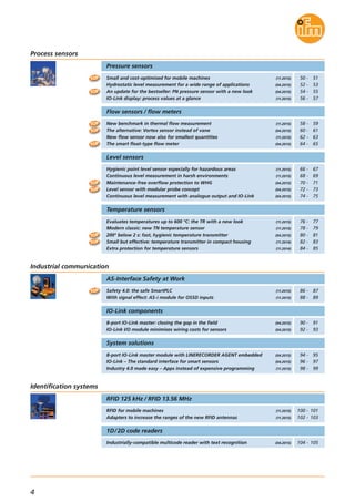
Inductive sensors
Position sensors
Dimensions
IFW204
IGW202
IIW202
Sensing range
[mm]
Current
load
[mA]
Switching
frequency
[Hz]
Order
number
M12 connector · 3 wire DC PNP · Output function normally open
65 4 1002000 IFW204M12
M18
M30
65 8 1002000 IGW202
65 15 1002000 IIW202
Installation
flush
flush
flush
Type Total length
[mm]
Operating voltage [V DC] 10...30
Current consumption [mA] < 20
Reverse polarity protection •
Short-circuit protection •
Overload protection •
Protection
IP 65 / IP 66 / IP 67 /
IP 68 / IP 69K
Protection class II
Ambient temperature [°C] -40...85
Housing materials
brass
anti-spatter,
sensing face LCP
Switching status indication [LED] yellow (4 x 90°)
Further technical data
Connection technology
Type Version Order
number
Socket, M12,
2 m grey, PUR cable
EVW001
Socket, M12,
5 m grey, PUR cable
EVW002
Socket, M12,
10 m grey, PUR cable
EVW003
Socket, M12,
2 m grey, PUR cable
EVW004
Socket, M12,
5 m grey, PUR cable
EVW005
Socket, M12,
10 m grey, PUR cable
EVW006
For further technical details please visit: www.ifm.com
Accessories
Type Version Order
number
M12 mounting sleeve with end stop,
anti-spatter
E12452
M18 mounting sleeve with end stop,
anti-spatter
E12453
M30 mounting sleeve with end stop,
anti-spatter
E12454
M12 washers,
anti-spatter
E12412
M18 washers,
anti-spatter
E12413
M30 washers,
anti-spatter
E12414
65
54
50
M12x1
M12x1
17
4
LED 4 x 90°
65
50
24
4
54
LED 4 x 90°
M18x1
M12x1
65
50
54
M12x1
36
M30x1,5
5
LED 4 x 90°](https://image.slidesharecdn.com/ifm-innovations-topproducts-2015-2016-gb-160202102146/85/Innovations-2015-2016-10-320.jpg)
![11
(04.2015)
Operating voltage [V DC] 24 (12...30)
Current consumption [mA] 30
Ambient temperature [°C] -40...85
Common technical data
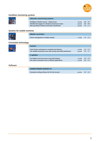
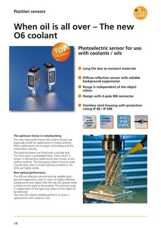
Capacitive sensors
Mounting options
The sensor can be installed in all housings with
a Ø 22.5 mm hole. The supplied lock nut is used
for fixing.
Thanks to the M22 thread the sensor can be used
for screw mounting without lock nut. Installation
alignment of the sensor is not necessary since the clip
showing the symbol for the sensing face is snapped
in as the last step.
Wiring is done via the tried-and-tested 3- or 4-wire
technology.
Position sensors
Connection Current rating
[mA]
Protection Order
no.
Output function NO · DC PNP
Housing material
dynamic
0.3 m PUR cable
with M12 plug
200IP 65, IP 67, IP 69K KT5102M22 PA
static
0.3 m PUR cable
with M12 plug
200IP 65, IP 67, IP 69K KT5106M22 PA
latching 2 m PUR cable 200IP 65, IP 67, IP 69K KT5150M22 PA
latching
0.3 m PUR cable
with M12 plug
200IP 65, IP 67, IP 69K KT5151M22 PA
latching 2 m PUR cable 200IP 65, IP 67, IP 69K KT5350M22 Stainless steel
latching
0.3 m PUR cable
with M12 plug
200IP 65, IP 67, IP 69K KT5351M22 Stainless steel
Type Evaluation principle
Accessories
Socket, M12,
2 m black, PUR cable
EVC001
Socket, M12,
5 m black, PUR cable
EVC002
Socket, M12,
2 m black, PUR cable
EVC004
Socket, M12,
5 m black, PUR cable
EVC005
Symbol disc must be ordered separately
For further technical data please go to: www.ifm.com
Connection technology
Type Description Order
no.
Symbol disc,
lettering: START
E12377
Symbol disc,
lettering: STOP
E12378
Symbol disc,
symbol: on
E12379
Symbol disc,
symbol: off
E12380
Symbol disc,
transparent
E12386
Type Description Order
no.
Plastic housing,
24 V DC, 2.5 A
DN1031
Power supplies
Output function NO · DC PNP · LED can be controlled separately
Type Description Order
no.
static 2 m PUR cable 200IP 65, IP 67, IP 69K KT5110M22 PA
dynamic 2 m PUR cable 200IP 65, IP 67, IP 69K KT5111M22 PA
dynamic
0.3 m PUR cable
with M12 plug
200IP 65, IP 67, IP 69K KT5112M22 PA
dynamic 2 m PUR cable 200IP 65, IP 67, IP 69K KT5309M22 Stainless steel
static 2 m PUR cable 200IP 65, IP 67, IP 69K KT5310M22 Stainless steel](https://image.slidesharecdn.com/ifm-innovations-topproducts-2015-2016-gb-160202102146/85/Innovations-2015-2016-12-320.jpg)
![13
(04.2015)
M12x1
10
1527,8
4
17
M12x1
9,7
7,8
60
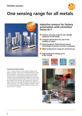
Magnetic sensors
Position sensors
For further technical details please visit: www.ifm.com
Connection technology
Type Description Order
no.
Socket, M12,
2 m black, PUR cable
EVC001
Socket, M12,
5 m black, PUR cable, LED
EVC008
Cable socket, M12, shielded, 120 °C
5 m black, PUR cable
E12339
Cable socket, M12, shielded, 120 °C
10 m black, PUR cable
E12340
Type Sensing
range
[mm]
Total length
[mm]
f
[Hz]
OutputAmbient
temperature
[°C]
Order
no.
Operating principle: magnetically biased
M12 1.8 f93 1000 PNP, normally open-25...120
M12 1.8 f93 1000 NPN, normally open-25...120
M12 1.8 f60 1000 PNP, normally open-25...120
M12 1.8 f60 1000 NPN, normally open-25...120
M12 1.8 f60 1000 PNP, normally closed-25...120
M14 1.8 f53 1000 PNP, normally open-25...85
Operating voltage [V] 10...36 DC
Current rating [mA] 200
Short-circuit protection,
pulsed
•
Reverse polarity /
overload protection
• / •
Protection rating,
protection class
IP 65 / IP 68 / IP 69K,
III
Connection M12 connector
Housing material
stainless steel
316L / 1.4404
Common technical data
Power supplies
Type Description Order
no.
Plastic housing,
24 V DC, 2.5 A
DN1031
Metal housing,
24 V DC, 3.3 A
DN4011
Dimensions
Example MFH202
L+
L
1
4
3
Wiring diagram
L+
L
1
2
3
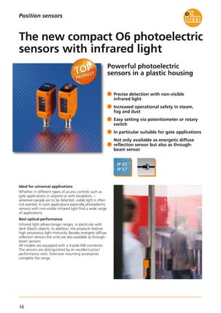
Two designs for many different requirements
The MFH with its standard M12 housing can be installed
and adjusted on many different hydraulic cylinders.
That is why most cylinder types are covered by only one
sensor.
Due to its end stop the M9H allows quick mounting.
The processing / installation time is reduced if always
the same cylinder type is used.
MFH200
MFH201
MFH202
MFH203
MFH204
M9H200](https://image.slidesharecdn.com/ifm-innovations-topproducts-2015-2016-gb-160202102146/85/Innovations-2015-2016-14-320.jpg)
![15
(11.2015)
Infrared sensors / red light sensors
Position sensors
For further technical details please visit: www.ifm.com
Diffuse reflection sensor with background suppression · 3-wire DC
Spot
diameter
[mm]
Connection
M8 connector
8*
Range
[mm]
2...200 4-pole
Current
consumption
[mA]
22
Diffuse reflection sensor · 3-wire DC
15*5...500 4-pole 16
Retro-reflective sensor with polarisation filter · 3-wire DC
150**50...5000 4-pole 12
Through-beam sensor – transmitter · 2-wire DC
300*0...10000 4-pole 11
Through-beam sensor – receiver · 3-wire DC
–0...10000 4-pole 7
Type of light,
wave length
[nm]
Red light, 633
Red light, 633
Red light, 645
Red light, 645
Red light, 645
* at maximum range, ** referred to prismatic reflector Ø 80 mm
Accessories
Type Description Order
no.
Common technical data
Operating voltage [V DC] 10...30
Switching status indication LED Yellow
Operation LED Green
Short-circuit protection, pulsed •
Reverse polarity protection /
overload protection
• / •
Ambient temperature [°C] -25...60
Voltage drop [V] < 2.5
Current rating [mA] 100
Materials Housing
Lens
Seal
High-grade stainless steel
(316L/1.4404), PPSU
PMMA
FKM
Switching frequency [Hz] 1000
Protection rating,
protection class
IP 65, IP 67, IP 68, IP 69 K,
III
O6H400O6H401
Order
no.
Order
no.
PNPNPN
O6T400O6T401
PNPNPN
O6P400O6P401
PNPNPN
O6S400
O6E400O6E401
PNPNPN
Angle bracket for free-standing
mounting, stainless steel
E21271
Protective bracket,
stainless steel
E21273
Mounting accessories
Plastic housing,
24 V DC, 2.5 A
DN1031
Metal housing,
24 V DC, 3.3 A
DN4011
Power supplies
Connection technology
Type Description Order
no.
Socket, M8, 4-pole
2 m black, PUR cable
EVC150
Socket, M8, 4-pole
5 m black, PUR cable
EVC151
Socket, M8, 4-pole
2 m black, PUR cable
EVC153
Socket, M8, 4-pole
5 m black, PUR cable
EVC154
Ø 50 mm, plastic E20956
Ø 80 mm, plastic E20005
48 x 48 mm, PMMA, ABS E20744
95 x 95 mm, plastic E20454
Prismatic reflectors
Mounting set for clamp mounting,
stainless steel, Ø 10 mm
E21272
Mounting set for clamp mounting,
stainless steel, Ø 12 mm
E21275
Rod, 120 mm, Ø 10 mm,
M8 thread, stainless steel
E21081
Rod, 100 mm, Ø 12 mm,
M10 thread, stainless steel
E20938](https://image.slidesharecdn.com/ifm-innovations-topproducts-2015-2016-gb-160202102146/85/Innovations-2015-2016-16-320.jpg)
![17
(04.2015)
Infrared sensors / red light sensors
Diffuse reflection sensor · 3-wire DC
Light spot diameter
[mm]
Connection Order
no.
15* O6T215
Range
[mm]
5...600 mm
M8 connector,
4-pole
Order
no.
O6T216
Position sensors
PNPNPN
Through-beam sensor - transmitter · 2-wire DC
300*0...15 m
M8 connector,
4-pole
O6S215
Through-beam sensor – receiver · 3-wire DC
– O6E2150...15 m
M8 connector,
4-pole
O6E216
PNPNPN
* at maximum range
Light-on / dark-on mode
• / •
adjustable
– / –
• / •
adjustable
For further technical details please visit: www.ifm.com
Accessories
Type Description Order
no.
Mounting set for clamp mounting,
stainless steel, Ø 10 mm
E21272
Mounting set for clamp mounting,
stainless steel, Ø 12 mm
E21275
Angle bracket for free-standing
mounting, stainless steel
E21271
Protective bracket,
stainless steel
E21273
Rod, 120 mm, Ø 10 mm,
M8 thread, stainless steel
E21081
Rod, 100 mm, Ø 12 mm,
M10 thread, stainless steel
E20938
Cube for mounting on an aluminium
profile, M8 thread, diecast zinc
E20950
Cube for mounting on an aluminium
profile, M10 thread, diecast zinc
E20951
Mounting accessories
Common technical data
Operating voltage [V DC] 10...30
Type of light Infrared light 850 nm
Switching status indication LED Yellow
Switching frequency [Hz] 1000
Protection rating,
protection class
IP 65 / IP 67,
III
Indication stable operation LED Green
Short-circuit protection, pulsed •
Reverse polarity protection /
Overload protection
• / •
Ambient temperature [°C] -25...60
Voltage drop [V] < 2.5
Current rating [mA] 100
Materials Housing
Lens
ABS
PMMA
Connection technology
Type Description Order
no.
Socket, M8, 4-pole
2 m black, PUR cable
EVC150
Socket, M8, 4-pole
5 m black, PUR cable
EVC151
Socket, M8, 4-pole
2 m black, PUR cable
EVC153
Socket, M8, 4-pole
5 m black, PUR cable
EVC154
Plastic housing,
24 V DC, 2.5 A
DN1031
Metal housing,
24 V DC, 3.3 A
DN4011
Power supplies](https://image.slidesharecdn.com/ifm-innovations-topproducts-2015-2016-gb-160202102146/85/Innovations-2015-2016-18-320.jpg)
![19
(11.2014)
Infrared sensors / red light sensors
Position sensors
For further technical details please visit: www.ifm.com
Diffuse reflection sensor with background suppression · 3-wire DC · PNP
Light spot diameter
[mm]
Connection
M8 connector
Order
no.
8* O6H309
Range
[mm]
2...200 4-pole
Current
consumption
[mA]
22
Diffuse reflection sensor · 3-wire DC · PNP
15* O6T3095...500 4-pole 16
Retro-reflective sensor with polarisation filter · 3-wire DC · PNP
150** O6P30950...5000 4-pole 12
Through-beam sensor - transmitter · 2-wire DC
300*0...10000 4-pole 11 O6S305
Through-beam sensor – receiver · 3-wire DC · PNP
– O6E3090...10000 4-pole 7
Communication
interface
IO-Link 1.1
IO-Link 1.1
IO-Link 1.1
IO-Link 1.1
IO-Link 1.1
* at maximum range
** referred to prismatic reflector Ø 80 mm
Accessories
Type Description Order
no.
Mounting set for clamp mounting,
stainless steel, Ø 10 mm
E21272
Angle bracket for free-standing
mounting, stainless steel
E21271
Rod, 120 mm, Ø 10 mm,
M8 thread, stainless steel
E21081
Memory plug, parameter memory
for IO-Link sensors
E30398
IO-Link interface, current consumption
from USB port
E30396
LINERECORDER SENSOR,
software for parameter setting and
set-up of IO-Link sensors
QA0001
Common technical data
Operating voltage [V DC] 10...30
Type of light red light 633 nm
Switching status indication LED yellow
Operation LED green
Short-circuit protection, pulsed •
Reverse polarity protection /
overload protection
• / •
Ambient temperature [°C] -25...80
Voltage drop [V] < 2.5
Current rating [mA] 100
Materials housing
lens
high-grade stainless steel
(316L/1.4404), PPSU
PMMA
Connection technology
Type Description Order
no.
M8 socket, 4-pole,
2 m orange, PVC cable
M8 socket, 4-pole,
5 m orange, PVC cable
M8 socket, 4-pole,
2 m orange, PVC cable
M8 socket, 4-pole,
5 m orange, PVC cable
Adapter cable
M12 plug to M8 socket 4-pole,
0.3 m orange, PVC cable
EVT248
Switching frequency [Hz] 1000
Protection rating,
protection class
IP 65, IP 67, IP 68, IP 69K,
III
Light-on / dark-on mode adjustable
18 x 18 mm, Solidchem plastic E21267
56 x 38 mm, Solidchem plastic E21268
48 x 48 mm, Solidchem plastic E21269
96 x 96 mm, Solidchem plastic E21270
EVT134
EVT135
EVT138
EVT139](https://image.slidesharecdn.com/ifm-innovations-topproducts-2015-2016-gb-160202102146/85/Innovations-2015-2016-20-320.jpg)

![21
(11.2014)
For further technical data please go to: www.ifm.com
Laser sensors / distance measurement sensors
Common technical data
Operating voltage [V DC] 10...30
Dimensions [mm] 56 x 18,2 x 46,5
Type of light
visible laser light
650 nm
Extraneous light on the object [klx] max. 8
Switching status indication LED yellow
Operation LED green
Distance value
3-digit
alphanumeric
display
Protection rating,
protection class
IP 65,IP 67
III
Short-circuit protection, pulsed •
Reverse polarity protection /
overload protection
• / •
Ambient temperature [°C] -25...60
Current rating [mA] 2 x 100
Output function
OUT1: NO
OUT2: NC
Position sensors
Connection technology
Type Description Order
no.
Socket, M12,
2 m black, PUR cable
EVC001
Socket, M12,
5 m black, PUR cable
EVC002
Socket, M12,
2 m black, PUR cable
EVC004
Socket, M12,
5 m black, PUR cable
EVC005
Photoelectric distance sensor, laser protection class 1 · M12 connector, complementary
Material housing / plug adapter
front pane / LED window
bezel
operator interface
PA
PMMA
stainless steel
TPU
Accessories
Type Description Order
no.
Mounting bracket for rod,
complete set incl. clamp
E21083
Protective bracket for rod,
complete set incl. clamp
E21084
Bracket for free-standing mounting E21087
Dovetail clamp E21088
Rod, 100 mm, Ø 12 mm,
M10 thread, stainless steel
E20938
Cube for mounting on an aluminium
profile, M10 thread, diecast zinc
E20951
Measuring
range
[mm]
Background
suppression
[m]
Switching
frequency
[Hz]
Spot Ø at
max. range
[mm]
Current
consumption
[mA]
Order
no.
Unit of
measurement
Hysteresis
[%]
Memory plug,
parameter memory for IO-Link sensors
E30398
IO-Link interface,
current consumption from USB port
E30396
LINERECORDER SENSOR,
software for parameter setting
and set-up of IO-Link sensors
QA0001
* in case of max. range
Metal housing,
24 V DC, 3.3 A
DN4011
Power supplies
Type Description Order
no.
30...2000 ...20 11 < 5 < 75 O5D151
30...2000 ...20 O5D15011 < 5 < 75 cm
inch< 7.5*
< 7.5*
PNP](https://image.slidesharecdn.com/ifm-innovations-topproducts-2015-2016-gb-160202102146/85/Innovations-2015-2016-22-320.jpg)

![23
(11.2014)
For further technical data please go to: www.ifm.com
Laser sensors / distance measurement sensors
Common technical data
Operating voltage [V DC] 10...30
Dimensions M30 x 90 mm
Type of light
visible laser light
650 nm
Extraneous light on the object [klx] max. 8
Switching status indication LED yellow
Operation LED green
Switch point (setting) radial setting ring
Protection rating,
protection class
IP 65,IP 67
III
Short-circuit protection, pulsed •
Reverse polarity protection /
overload protection
• / •
Ambient temperature [°C] -25...60
Current rating [mA] 2 x 100
Output function
OUT1: NO
OUT2: NC
Position sensors
Connection technology
Type Description Order
no.
Socket, M12,
2 m black, PUR cable
EVC001
Socket, M12,
5 m black, PUR cable
EVC002
Socket, M12,
2 m black, PUR cable
EVC004
Socket, M12,
5 m black, PUR cable
EVC005
Photoelectric distance sensor, laser protection class 1 · M12 connector, complementary
Measuring
range
[mm]
Background
suppression
[m]
Switching
frequency
[Hz]
Spot Ø at
max. range
[mm]
Current
consumption
[mA]
Order
no.
Unit of
measurement
Hysteresis
[%]
Material housing
front pane
stainless steel,
PBT, PC, FPM
PMMA
Rod, 100 mm, Ø 12 mm,
M10 thread, stainless steel
E20938
Cube for mounting on an aluminium
profile, M10 thread, diecast zinc
E20951
Type Description Order
no.
Accessories
Angle bracket for type M30,
stainless steel
E10737
Mounting clamp for types M30, PTB E10077
Mounting set Ø 30.2 mm,
clamp mounting, aluminium profile
E20875
Mounting set Ø 30.2 mm,
clamp mounting
E20873
Mounting set Ø 30.2 mm, clamp
mounting, high-grade stainless steel
E20874
Mounting clamp,
with end stop for types M30, PC
E11049
Memory plug,
parameter memory for IO-Link sensors
E30398
IO-Link interface,
current consumption from USB port
E30396
LINERECORDER SENSOR,
software for parameter setting
and set-up of IO-Link sensors
QA0001
* in case of max. range
Metal housing,
24 V DC, 3.3 A
DN4011
Power supplies
Type Description Order
no.
30...2000 ...20 11 < 5 < 75 OID251
30...2000 ...20 OID25011
< 5*
< 5* < 5 < 75 cm / inch
cm
PNP](https://image.slidesharecdn.com/ifm-innovations-topproducts-2015-2016-gb-160202102146/85/Innovations-2015-2016-24-320.jpg)

![25
(04.2015)
Laser sensors / distance measurement sensors
Common technical data
Operating voltage [V DC] 10...30
Dimensions M30 x 70 mm
Type of light
Visible laser light
650 Nm,
can be switched off via
pin 5 or IO-Link
Extraneous light on the object [klx] Max. 8
Switching status indication LED Yellow
Switch point
(set)
via IO-Link 1.1
Protection rating,
protection class
IP 65, IP 67, IP 68, IP 69K
III
Short-circuit protection, pulsed •
Reverse polarity protection /
overload protection
• / •
Ambient temperature [°C] -25...60
Current rating [mA] 2 x 100
Output function
OUT1: NO
OUT2: NC
For further technical details please visit: www.ifm.com
Position sensors
Connection technology
Type Description Order
no.
Socket, M12, 5-pole,
2 m black, PUR cable
EVC073
Socket, M12, 5-pole,
5 m black, PUR cable
EVC074
Socket, M12, 5-pole,
5 m black, PVC cable
EVT013
Photoelectric distance sensor · M12 connector, complementary
Measuring
range
[mm]
Background
suppression
[m]
Switching
frequency
[Hz]
Spot Ø at
max. range
[mm]
Current
consumption
[mA]
Order
no.
30...2000 ...20 11 < 5 < 75 OID254
Laser
protection
class
30...2000 ...20 OID20411
Hysteresis
[%]
< 2.5...5*
< 1.5...3* < 5 < 75 2
1
Material Housing
Front pane
Stainless steel
PMMA
Cube for mounting on an aluminium
profile, M10 thread, diecast zinc
E20951
Type Description Order
no.
Accessories
Angle bracket for type M30,
stainless steel
E10737
Mounting clamp for types M30, PTB E10077
Mounting clamp, with end stop
for types M30, PC
E11049
Memory plug, parameter memory
for IO-Link sensors
E30398
IO-Link interface,
current consumption from USB port
E30396
LINERECORDER SENSOR,
software for parameter setting and
setting up IO-Link sensors
QA0001
* at max. range
PNP
Hysteresis
500 1000 1500 20000
0
25
50
75
100
125
150
175
200
y
x
2 b
1 b
2 a
1 a
x: Distance in [mm], y: Hysteresis in [mm]
1. Background black (6 % remission)
2. Background white (90 % remission)
Laser protection class 1
Laser protection class 2](https://image.slidesharecdn.com/ifm-innovations-topproducts-2015-2016-gb-160202102146/85/Innovations-2015-2016-26-320.jpg)

![27
(04.2015)
Encoders
For further technical details please visit: www.ifm.com
Sensors for motion control
Flange IO-LinkResolution
[pulse/revolution]
Order
no.
Hollow shaft with integrated stator coupling· 4-digit display · Integrated pulse evaluation
direct •max. 10,000 (adjustable) ROP52012
Operating voltage
[V DC]
4.5...30
Shaft Ø
[mm]
Solid shaft · 4-digit display · Integrated pulse evaluation
servo •max. 10,000 (adjustable) RUP5006 4.5...30
clamp flange •max. 10,000 (adjustable) RVP51010 4.5...30
Protection IP 65, IP 67
Connection
M12 connector
(rotatable)
Further technical data
58
58
58
Housing Ø
[mm]
Switching frequency [kHz] 300
Accessories
Type Description Order
no.
Spring disc coupling,
Ø 6 mm / 10 mm, die-cast zinc; PA
E60117
Spring disc coupling,
Ø 10 mm / 10 mm, die-cast zinc; PA
E60118
Flexible coupling with clamp connection,
Ø 6 mm / 10 mm, aluminium
E60066
Flexible coupling with clamp connection,
Ø 10 mm / 10 mm, aluminium
E60067
Flexible coupling with adjusting screws,
Ø 10 mm / 10 mm, aluminium
E60022
Flexible coupling with adjusting screws,
Ø 6 mm / 10 mm, aluminium
E60028
Measuring wheel,
Ø 159.15 mm / 10 mm, Hytrel TPE-E
E60110
Measuring wheel,
Ø 159.16 mm / 10 mm, aluminium, PU
E60076
Measuring wheel,
Ø 63.66 ± 0.1 mm / 10 mm, Hytrel TPE-E
E60138
Measuring wheel,
Ø 63.6 mm, 10 mm, aluminium
E60095
Measuring wheel,
Ø 63.66 ± 0.1 mm / 6 mm, aluminium
E60137
Measuring wheel,
Ø 63.6 mm, 6 mm, aluminium
E60006
Angle bracket for RUP design,
aluminium, black anodised
E60033
Angle bracket for RUP design,
aluminium, black anodised
E60035
Fastening clamp for
synchro flange, steel
E60041
Memory plug, parameter memory
for IO-Link sensors
E30398
LINERECORDER SENSOR,
Software for parameter setting and
set-up of IO-Link sensors
QA0001
Accessories
Type Description Order
no.
Connection technology
Type Description Order
no.
M12 socket, shielded,
5 m black , PUR cable, 8 poles
E12403
M12 socket, shielded,
10 m black , PUR cable, 8 poles
E12404
M12 socket, shielded,
2 m black , PUR cable, 8 poles
E12402
USB IO-Link master for parameter setting
and analysis of units
Supported communication protocols:
IO-Link (4.8, 38.4 and 230 Kbits/s)
E30390
Adapter cable for the connection
between USB IO-Link master E30390
and 4-pole / 8-pole encoder
E12432](https://image.slidesharecdn.com/ifm-innovations-topproducts-2015-2016-gb-160202102146/85/Innovations-2015-2016-28-320.jpg)
![29
(04.2015)
Encoders
For further technical details please visit: www.ifm.com
Accessories
Type Description Order
no.
Spring disc coupling,
Ø 6 mm / 10 mm, die-cast zinc; PA
E60117
Spring disc coupling,
Ø 10 mm / 10 mm, die-cast zinc; PA
E60118
Flexible coupling with clamp connection,
Ø 6 mm / 10 mm, aluminium
E60066
Flexible coupling with clamp connection,
Ø 10 mm / 10 mm, aluminium
E60067
Flexible coupling with adjusting screws,
Ø 10 mm / 10 mm, aluminium
E60022
Flexible coupling with adjusting screws,
Ø 6 mm / 10 mm, aluminium
E60028
Measuring wheel,
Ø 159.15 mm / 10 mm, Hytrel TPE-E
E60110
Measuring wheel,
Ø 159.16 mm / 10 mm, aluminium, PU
E60076
Measuring wheel,
Ø 63.66 ± 0.1 mm / 10 mm, Hytrel TPE-E
E60138
Measuring wheel,
Ø 63.6 mm, 10 mm, aluminium
E60095
Measuring wheel,
Ø 63.66 ± 0.1 mm / 6 mm, aluminium
E60137
Measuring wheel,
Ø 63.6 mm, 6 mm, aluminium
E60006
Sensors for motion control
Flange IO-LinkResolution
[pulse/revolution]
Order
no.
Hollow shaft with integrated stator coupling
direct •max. 10,000 (adjustable) RA31006
Connection
M12
direct •max. 10,000 (adjustable) RA35006 cable, 2 m
direct •max. 10,000 (adjustable) RO310012 M12
direct •max. 10,000 (adjustable) RO350012 cable, 2 m
Shaft Ø
[mm]
Solid shaft
universal •max. 10,000 (adjustable) RB31006 M12
universal •max. 10,000 (adjustable) RB35006 cable, 2 m
servo •max. 10,000 (adjustable) RU31006 M12
servo •max. 10,000 (adjustable) RU35006 cable, 2 m
clamp flange •max. 10,000 (adjustable) RV310010 M12
clamp flange •max. 10,000 (adjustable) RV350010
36.5
36.5
58
58
Housing Ø
[mm]
36.5
36.5
58
58
58
58 cable, 2 m
Angle bracket for RB and RU design,
aluminium, black anodised
E60033
Angle bracket for RV design,
aluminium, black anodised
E60035
Switching frequency [kHz] 300
Operating voltage [V DC] 4.5...30
Protection IP 65, IP 67
Further technical data
Memory plug, parameter memory
for IO-Link sensors
E30398
LINERECORDER SENSOR,
software for parameter setting and
set-up of IO-Link sensors
QA0001
Accessories
Type Description Order
no.Fastening clamp for
synchro flange, steel
E60041
USB IO-Link master for parameter setting
and analysis of units
Supported communication protocols:
IO-Link (4.8, 38.4 and 230 Kbits/s)
E30390
Connection technology
Type Description Order
no.
M12 socket, shielded,
5 m black, PUR cable, 5 poles
EVC545
M12 socket, shielded,
10 m black, PUR cable, 5 poles
EVC546
M12 socket, shielded,
2 m black, PUR cable, 5 poles
EVC544](https://image.slidesharecdn.com/ifm-innovations-topproducts-2015-2016-gb-160202102146/85/Innovations-2015-2016-30-320.jpg)
![31
(11.2015)
90
75
22
45
62
5,3
36
4,5
Operating voltage [V DC]
with:
Switching and current outputs
Voltage output
IO-Link connection
9.2...30
12...30
18...30
Reverse polarity protection •
Angular range
Absolute accuracy
Repeatability
Resolution
JN2200
±180°/± 90°
≤ ± 0.5°
≤ ± 0.1°
≤ ± 0.05°
JN2201
± 45°
≤ ± 0.1°
≤ ± 0.05°
≤ ± 0.01°
Ambient temperature [°C] -40...85
Temperature coefficient [°/K] ≤ ± 0.002
Protection rating
IP 65 / IP 67 / IP 68 /
IP 69K
Number of measurement axes
with inclination
2
Frequency range [Hz] 0.1...400
Measuring range [g] ± 2, ± 4, ± 8
2
0.5...50
± 2
Number of measurement axes
with vibration
3 –
Housing material
diecast zinc
nickel-plated
Connection
2 x
M12 connector
(4 poles; A-coded)
Technical data
JN2200, JN2201
Inclination sensors
Connection technology
Type Description Order
no.
Socket, M12,
2 m black, PUR cable
EVM039
Socket, M12,
10 m black, PUR cable
EVM041
Socket, M12,
2 m black, PUR cable
EVM036
Socket, M12,
10 m black, PUR cable
EVM038
Jumper, M12,
5 m black, PUR cable
EVC069
Jumper, M12,
5 m black, PUR cable
EVC059
Accessories
Description Order
no.
Dimensions
Type
For further technical details please visit: www.ifm.com
Sensors for motion control
The products
Description Order
no.
Angular range ± 180° / ± 90°,
IO-Link
JN2200
Angular range ± 45°,
IO-Link
JN2201
Type
Communication interface
IO-Link 1.1,
COM 2,
38.4 kbaud
LINERECORDER SENSOR
Software for parameter setting and
set-up of IO-Link sensors
QA0001
USB IO-Link master for parameter setting
and analysis of units
Supported communication protocols:
IO-Link (4.8, 38.4 and 230 kBit/s)
E30390
Memory plug, parameter memory
for IO-Link sensors
E30398](https://image.slidesharecdn.com/ifm-innovations-topproducts-2015-2016-gb-160202102146/85/Innovations-2015-2016-32-320.jpg)

![33
(11.2014)
Operating voltage [V DC] 9.2...30
Reverse polarity protection •
Angular range
Resolution
Repeatability
JN2100
JN2300
± 180°
0.05°
≤ ± 0.1°
JN2101
JN2301
± 45°
0.01°
≤ ± 0.05°
Ambient temperature [°C]
Temperature coefficient [°/K] ≤ ± 0.002°
Protection
IP 65 / IP 67 / IP 68 /
IP 69K
Data interface
CANopen
Device profile
CiA DSP-410 /
SAE J1939
Limit frequency inclination [Hz]
adjustable:
10, 5, 1, 0.5
Filter for [Hz]
vibration monitoring
0.1...1, 0.1...10, 1...10,
2...400, 10...400
Housing material
Diecast zinc
nickel-plated
Connection
2 x
M12 connector
Technical data
JN2100, JN2101,JN2300, JN2301
Inclination sensors
Connection technology
Type Description Order
no.
Socket, M12,
2 m black, PUR cable
EVM039
Socket, M12,
10 m black, PUR cable
EVM041
Socket, M12,
2 m black, PUR cable
EVM036
Socket, M12,
10 m black, PUR cable
EVM038
Accessories
Description Order
no.
Adapter cable for CAN devices with
M12 connector (5 pole)
EC2062
Dimensions
36
4,5
90
75
22
45
60
5,3
Flexible, precise, reliable
Since zero point, direction of counting and limit
frequency can be set for a stable output signal, the
sensors can be adapted precisely to your application.
Very low temperature drift across the whole tempera-
ture range provides unrivalled reliability.
Ideal for different applications
The sensors allow complete CAN integration
according to the CANopen communication profiles,
CiA DSP-410 and CiA DS-301 profiles.
They are connected via an M12 connector. The
terminating resistor can be enabled.
The sensors provide the signals either as perpendicular
angle, Euler angle or Gimbal angle.
Type
Sensors for motion control
For further technical details please visit: www.ifm.com
Jumper, M12,
5 m, black, PUR cable
EVC069
Jumper, M12,
5 m, black, PUR cable
EVC059
-40...85
Number of measurement axes
for inclination
2
Number of measurement axes
for vibration
3 –
The products
Description Order
no.
Angular range ± 180°,
CANopen
JN2100
Angular range ± 45°,
CANopen
JN2101
Angular range ± 180°,
SAE J1939
JN2300
Angular range ± 45°,
SAE J1939
JN2301
Type](https://image.slidesharecdn.com/ifm-innovations-topproducts-2015-2016-gb-160202102146/85/Innovations-2015-2016-34-320.jpg)
![35
(04.2015)
Further technical dataOperating principle DL0201
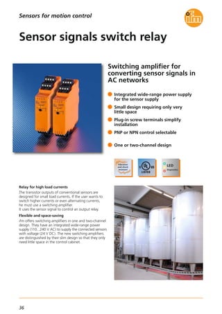
The DL0201 evaluation unit is actually a timer. When it
receives a signal from the connected sensor, it switches
the relay change-over contact for a certain period of
time. By means of two scaled potentiometers the user
can set the time between 0 and 60 seconds or 0 and
60 minutes. Adjustable switch-on and switch-off delays
act as damping. This suppresses brief fluctuations
around the sensor switch.
In addition the evaluation unit has an enable function
by means of which control can be bridged manually. A
leakage sensor can also be integrated into the control
function by means of the enable input.
Application example
The upper level in a tank is monitored via a capacitive
sensor. When the level has been reached, the sensor
provides a signal to the evaluation unit. It closes the
supply valve for the time set to prevent overfilling. The
damping function prevents, for example, one single
wave generating a switching signal.
Operating principle DL0203
It is a typical two-point control. When a sensor provides
a signal, the relay change-over contact switches until
the second sensor provides a signal for switch-off.
A switch-on delay is available that acts as damping and
suppresses short-term fluctuations around the sensor
switch point.
Application example
To protect a pump against running dry two capacitive
sensors are installed on the storage tank. When the
lower minimum level has been reached, the sensor
provides a signal to the evaluation unit. With the relay
output it switches off the pump that is normally used
to empty the tank.
When the upper level has been reached, the second
sensor installed there switches, the relay in the evaluation
unit switches on again and the pump is started.
Systems for pulse evaluation
Sensors for motion control
Nominal voltage
[V]
Outputs
Relays / transistors
Auxiliary energy
for sensors
Order
no.
Limit level monitoring (overflow, running dry, leakage)
110...240 AC
(50...60 Hz) / 27 DC
(typ. 24 DC)
1 / 1
typ. 18.5...30 V DC /
≤ 100 mA
short circuit /
overload protected
DL0201
Relay outputs
1 x changeover contact
4 A
(240 V AC, 24 V DC);
resistive load
Transistor outputs
1 x PNP /
externally supplied
10...30 V DC SELV /
≤ 100 mA
Ambient temperature [°C] -25...60
Storage temperature [°C] -25...70
Protection
housing / terminals
IP 20 / IP 20
Connection
4-pole connector
with screw connection,
5.0 mm pitch
For further technical details please visit: www.ifm.com
Type Inputs
Signal / enable
Input
frequency
[Hz]
1 x PNP / 1 x PNP
(type 2
acc. to IEC 61131-2)
≤ 5
Two-point control of levels
110...240 AC
(50...60 Hz) / 27 DC
(typ. 24 DC)
1 / 1
typ. 18.5...30 V DC /
≤ 100 mA
short circuit /
overload protected
DL0203
2 x PNP / –
(type 2
acc. to IEC 61131-2)
≤ 5
Display DL0201 LED
Power supply
Input
Output
Enable
Green
Yellow
Green (lights if
relay energised
and transistor
switched)
Green (lights if
enable signal is present)
Display DL0203 LED
Power supply
Input
Output
Green
2 x yellow
Green (lights if
relay energised
and transistor
switched)
Accessories
Type Description Order
no.
Connector,
4 poles with screw terminals,
pack of 5
(supplied)
E40173
Connector,
4 poles with cage clamps,
pack of 5
E40171](https://image.slidesharecdn.com/ifm-innovations-topproducts-2015-2016-gb-160202102146/85/Innovations-2015-2016-36-320.jpg)
![37
(04.2015)
25,4 109,1
93
LEDs
3
2
4
35,5
112,6
1
Sensors for motion control
For further technical details please visit: www.ifm.com
Systems for pulse evaluation
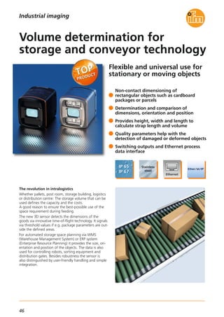
Dimensions
DN0220
1) plug-in screw terminals
2) panel for labelling
3) potentiometer
4) DIN rail mounting
Type Ub
[V]
Pulse
input
Inputs Auxiliary energy
for sensors
Input
frequency
[Hz]
Order
no.
Application: power supply and signal evaluation (e.g. for sensors)
110...240 AC
50...60 Hz
PNP / NPN1
24 V DC,
300 mA
≤ 10 DN0210
110...240 AC
50...60 Hz
PNP / NPN2
24 V DC,
2 x 150 mA
≤ 10
Outputs
Relay
1
2 DN0220
Relay output
Contact rating [A]
4 (240 V AC, 24 V DC);
resistive load
Auxiliary energy for sensors [V]
24 DC SELV, ± 10 %,
300 mA,
short-circuit and
overload protected
Protection
housing / terminals
IP 20 / IP 20
Ambient temperature [°C] -20...60
Display DN0210 LED
Power supply
Output
Fault
1 x green
1 x yellow (lights,
if output relay
is energised)
1 x red
Display DN0220 LED
Power supply
Output
Fault
1 x green
2 x yellow (light,
if output relay
is energised)
1 x red
Potentiometer
Selection
PNP / NPN
Housing material
Plastic:
PC GF20
Mounting
Rail TH35
(according to EN 60715)
Connection
Unit:
4-pole terminal blocks
with 5.0 mm pitch;
Connector:
4 poles with
screw connection
Further technical data
Setting range:
selectable for PNP and NPN switching sensors
Wiring diagram
Accessories
Type Description Order
no.
Connector,
4 poles with screw terminals,
pack of 5
(supplied)
E40173
Connector,
4 poles with cage clamps,
pack of 5
E40171
Power
21 22 23 24
AC
L L N N
In
12
9 Sensor
supply
10 pnp/npn
Out7
6
5
8
Power
21 22 23 24
AC
L L N N
In
2
16
13 Sensor
supply
14 pnp/npn
In
1
12
9 Sensor
supply
10 pnp/npn
Out
2
19
18
17
20
Out
1
7
6
5
8
DN0210 (1-channel) DN0220 (2-channel)](https://image.slidesharecdn.com/ifm-innovations-topproducts-2015-2016-gb-160202102146/85/Innovations-2015-2016-38-320.jpg)

![39
(04.2015)
Easy setting of the limit speed
The speed is determined via the interval measurement
on the inputs where for example two inductive sensors
are used as pulse pick-ups.
The user can set the limit speed easily and effectively
via three rotary switches (x 1, x 10, multiplier) – either
in rpm or Hz. It was decided not to use any complicated
setting menus.
An easy and intuitive setting algorithm prevents
unintentional change or manipulation of the set values.
More functions
Automatic or manual reset of underspeed is possible.
This function is set via wire links.
The monitoring function can be enabled and disabled
via a switching input.
Besides the 2-pole safety relay, transistor outputs can
also be used as output for the status and error indication.
For further technical details please visit: www.ifm.com
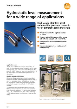
Dimensions
22,5
99
108
1
LED
2
114,5
3
35,5
Systems for pulse evaluation
Sensors for motion control
1) Screw terminals
2) Rotary switch
3) DIN rail mounting
Wiring diagram
L- L+ S33 S34 S35 S44 S43 S45 13 23
(GND) (GND)
Y3 Y4 Y2 Y1 Y5 Y6 Y7 Y8 14 24
VCC = 24 V DC
24 V DC
Sensor 2Sensor 1
K1
K2K1
K2
Enable 1
Enable 2
Fault Overspeed
24 VRestart
Accessories
Type Description Order
no.
Plastic housing,
24 V DC, 2.5 A
DN1031
Metal housing,
24 V DC, 3.3 A
DN4011
Power supplies
Safety speed monitor
DU110S
Evaluation system for safe speed monitoring
Operating voltage [V DC]
19.2...28.8;
incl. 5 %
residual ripple
Nominal voltage [V DC] 24
Current consumption [mA] ≤ 125
Sensor supply 24 V DC / ≤ 70 mA
Protection IP 20 / II
Input characteristics
Pulse inputs
S34, S43:
“1”: 6 mA / 24 V DC
Adjustable speed range [rpm] 10...49500
Adjustable frequency range [Hz] 0.1...990
Input frequency [Hz] ≤ 5000
Output function
2 safety-related switching
outputs (floating contacts)
1 fault output “Fault”
(positive switching)
1 diagnostic output
“Overspeed”
(positive switching)
Output characteristics
Fault output “Fault” Y7
and diagnostic output
“Overspeed” Y8
≤ 20 mA, 24 V DC,
voltage drop ≤ 2 V DC,
short-circuit proof,
non safe
Contact rating
6 A,
250 V AC / 24 V DC
(≥ 6 mA);
resistive load
Ambient temperature [°C] -40...55
Storage temperature [°C] -40...75
Max. permissible relative [%]
humidity
95,
non condensing
Housing materials
PA
(polyamide)
Mounting
Rail TH35
(according to EN 60715)
Connection
Screw terminals;
0.5...2.5 mm²
(AWG 12...30)
Technical data](https://image.slidesharecdn.com/ifm-innovations-topproducts-2015-2016-gb-160202102146/85/Innovations-2015-2016-40-320.jpg)

![41
(11.2014)
Camera systems for
mobile machines
Description Order
no.
IR system illumination unit (850 nm) for mobile
3D sensors
O3M950
Further technical data
Smart sensor O3M151
Accessories
Housing material diecast aluminium
Device connection M12 connector
Protection rating,
protection class
IP 67 / IP 69K,
III
Operating voltage [V DC] 9...32
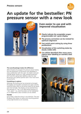
Functions and advantages
Powerful 3D time-of-flight measurement (ToF)
The principle of this 3D sensor is based on ifm’s patented
and award-winning pmd technology. It was specifically
designed for outdoor use and difficult ambient light
situations. Even interference such as sunlight or materials
with different reflective characteristics do not influence
the repeatability of the measured data.
Powerful electronics
The integrated 2 x 32-bit processor architecture ensures
a rapid and reliable calculation of the 3D data and
functions directly integrated in the system with up to
50 fps. The complete electronics of the mobile 3D smart
sensor is optimised and adapted to the demands and
requirements of mobile machines.
Besides shock and vibration resistance self-diagnostic
functions from the sensor to the IR system illumination
unit are of course also available.
Smart functions
The mobile 3D smart sensor integrates some functions
which enable to solve a multitude of applications.
A highly developed algorithm from the automotive
industry is used ensuring, for example, reliable automatic
object recognition of up to 20 objects. This function
can, for example, be used as collision warning.
For simple distance tasks typical functions such as
minimum / maximum / average distance are available.
System parameter setting and monitoring
The parameter setting of the system and live monitoring
of the 3D data are carried out via the easy-to-use ifm
vision wizard for Windows. As an alternative, parameter
setting can also be carried out via function blocks using
the software CODESYS.
Communication interfaces
The preprocessed function data is output via the CAN
bus using CANopen or SAE J 1939. If needed, the
complete 3D information can be processed at the same
time via Ethernet UDP and an external process unit.
Current consumption sensor [mA] < 400
Current consumption [A]
system illumination unit
< 5
Ambient temperature [°C] -40...85
Interfaces
1x CAN,
1 x fast Ethernet
Supported CAN protocols
CANopen,
SAE J 1939
Standards and tests
(extract)
CE,
E1 (UN-ECE R10)
For further technical details please visit: www.ifm.com
Industrial imaging
CAN/RS232 USB interface CANfox EC2112
Adapter cable set for CANfox EC2114
Operating software for vision sensors E3D300
U-shaped holder,
suitable for sensor or illumination unit
E3M100
Mounting set for clamp mounting,
Ø 14mm, stainless steel
E3M103
Connection technology
MCI cable, connection
sensor / system illumination unit, 1 m
E3M121
MCI cable, connection
sensor / system illumination unit, 2 m
E3M122
Type Description Order
no.
M12 socket, voltage supply system
illumination unit, 2 m,
PUR cable, 4 poles
E3M131
M12 socket, voltage supply system
illumination unit, 10 m,
PUR cable, 4 poles
E3M133
Ethernet, cross-over patch cable,
2 m, PVC cable, M12 / RJ45
E11898
Ethernet, cross-over patch cable,
10 m, PVC cable, M12 / RJ45
E12204
Type of sensor Resolution
pixels
[pixel]
IlluminationAngle of aperture
horizontal x vertical
[°]
Order
no.
PMD 3D sensor · Type O3M · M12 connector
PMD 3D chip 64 x 16
ext. illumination
required
70 x 23 O3M151
Max.
sampling rate
[Hz]
25/33/50](https://image.slidesharecdn.com/ifm-innovations-topproducts-2015-2016-gb-160202102146/85/Innovations-2015-2016-42-320.jpg)

![43
(11.2014)
Camera systems for
mobile machines
Further technical data
O3M150
Housing material diecast aluminium
Device connection M12 connector
Protection rating,
protection class
IP 67 / IP 69K,
III
Operating voltage [V DC] 9...32
Functions and advantages
Powerful 3D time-of-flight measurement (ToF)
The principle of this 3D sensor is based on ifm’s patented
and award-winning pmd technology. It was specifically
designed for outdoor use and difficult ambient light
situations. Interference such as sunlight or materials
with different reflective characteristics which occurs in
the area of mobile machines does not influence the
repeatability of the measured data.
Powerful electronics
The integrated 2 x 32-bit processor architecture ensures
a rapid and reliable calculation of the distance image to
be output with up to 50 fps. The complete electronics
of the mobile 3D sensor is optimised and adapted to the
demands and requirements of mobile machines.
Besides shock and vibration resistance self-diagnostic
functions from the sensor to the IR system illumination
unit are of course also available.
High system uptime
The system has various features to ensure uninterrupted
operation. They include, among others, a temperature-
controlled front lens heating, soiling indication as well
as different status information which can be fetched
from CAN.
System parameter setting and monitoring
The parameter setting of the system and live monitoring
of the 3D data are carried out via the easy-to-use ifm
vision wizard for Windows. As an alternative, parameter
setting can also be carried out via function blocks using
the software CODESYS.
Communication interfaces
The mobile 3D sensor features a fast Ethernet interface
(100 Mbit) as well as a CAN interface. The data output
of the complete 3D information is carried out via
Ethernet UDP and can be processed using a process
unit at the customer’s end. For this version the CAN in-
terface is only intended for parameter setting and
status output.
Current consumption sensor [mA] < 400
Current consumption [A]
system illumination unit
< 5
Ambient temperature [°C] -40...85
Interfaces
1x CAN,
1 x fast Ethernet
Supported CAN protocols
CANopen,
SAE J 1939
Standards and tests
(extract)
CE,
E1 (UN-ECE R10)
For further technical details please visit: www.ifm.com
Industrial imaging
Description Order
no.
IR system illumination unit (850 nm) for mobile
3D sensors
O3M950
Accessories
CAN/RS232 USB interface CANfox EC2112
Adapter cable set for CANfox EC2114
Operating software for vision sensors E3D300
U-shaped bracket,
suitable for sensor or illumination unit
E3M100
Mounting set for clamp mounting,
Ø 14mm, stainless steel
E3M103
Connection technology
MCI cable, connection
sensor / system illumination unit, 1 m
E3M121
MCI cable, connection
sensor / system illumination unit, 2 m
E3M122
Type Description Order
no.
M12 socket, voltage supply system
illumination unit, 2 m,
PUR cable, 4 poles
E3M131
M12 socket, voltage supply system
illumination unit, 10 m,
PUR cable, 4 poles
E3M133
Ethernet, cross-over patch cable,
2 m, PVC cable, M12 / RJ45
E11898
Ethernet, cross-over patch cable,
10 m, PVC cable, M12 / RJ45
E12204
Type of sensor Resolution
pixels
[pixel]
IlluminationAngle of aperture
horizontal x vertical
[°]
Order
no.
PMD 3D sensor · Type O3M · M12 connector
PMD 3D chip 64 x 16
ext. illumination
required
70 x 23 O3M150
Max.
sampling rate
[Hz]
25/33/50](https://image.slidesharecdn.com/ifm-innovations-topproducts-2015-2016-gb-160202102146/85/Innovations-2015-2016-44-320.jpg)

![45
(11.2015)
3D sensors
Mounting set for O3D E3D301
Further technical data
Accessories
Operating voltage [V DC] 20.4...28.8
Current consumption [mA]
< 2400 peak current
pulsed;
typ. mean value
420
Current rating [mA]
(per switching output)
100
Real chip resolution
25,000 /
100,000
Resulting resolution
176 x 132
pixels
Function display LED
2 x yellow,
2 x green
Illumination
850 nm,
infrared
Ambient light [lux]
Max. 10,000
(indoor)
Trigger
External;
24 V PNP/NPN
according to
IEC 61131-2 type 3
Switching inputs
2
(configurable),
24 V PNP/NPN
according to
IEC 61131-2 type 3
Switching outputs
3
(configurable),
24 V PNP/NPN,
according to
IEC 61131-2
Ambient temperature [°C] -10...50
For further technical details please visit: www.ifm.com
Industrial imaging
Connection technology
Type Description Order
no.
Ethernet, cross-over patch cable,
2 m, PVC cable, M12 / RJ45
E11898
Ethernet jumper,
2 m, PVC cable, M12 / M12
E21138
Type of sensor Material
front pane /
LED window
Angle of aperture
[°]
Protection rating,
protection class
Order
no.
PMD 3D sensors · Type O3D · M12 connector
PMD 3D ToF chip
Gorilla glass /
polyamide
Material
housing
Aluminium 40 x 30
IP 65 / IP 67,
III
O3D300
Max.
field of view size
[m]
2.61 x 3.47
PMD 3D ToF chip
Gorilla glass /
polyamide
Aluminium 60 x 45
IP 65 / IP 67,
III
O3D3023.75 x 5.00
PMD 3D ToF chip
Polycarbonate /
polyamide
Stainless steel 40 x 30
IP 66 / IP 67,
III
O3D3102.61 x 3.47
PMD 3D ToF chip
Polycarbonate /
polyamide
Stainless steel 60 x 45
IP 66 / IP 67,
III
O3D3123.75 x 5.00
Socket, M12,
2 m black, PUR cable, 8 poles
E11950
Type Description Order
no.
Short-circuit protection, pulsed •
Overload protection •
Parameter setting interface
Ethernet
10 Base-T /100 Base-TX
Possible parameter settings
Via PC /
notebook
Dimensions (H, W, D) [mm] 72 x 65 x 85
Technical data
Completeness monitoring
Operating distance [m] 0.3...5
Max. handling unit size 64 objects
Sampling rate / [Hz]
switching frequency
The image repetition frequency is
reduced by using the position tracking
function
10
Minimum size of objects [mm]
Object speed: 0...0.2 m/s
Object speed: > 0.2 m/s
25
45](https://image.slidesharecdn.com/ifm-innovations-topproducts-2015-2016-gb-160202102146/85/Innovations-2015-2016-46-320.jpg)
![47
(11.2015)
3D sensors
Mounting set for O3D E3D301
Further technical data
Accessories
For further technical details please visit: www.ifm.com
Industrial imaging
Connection technology
Type Description Order
no.
Ethernet, cross-over patch cable,
2 m, PVC cable, M12 / RJ45
E11898
Ethernet jumper,
2 m, PVC cable, M12 / M12
E21138
Type of sensor Material
front pane /
LED window
Angle of aperture
[°]
Protection rating,
protection class
Order
no.
PMD 3D sensors · Type O3D · M12 connector
PMD 3D ToF chip
Gorilla glass /
polyamide
Material
housing
Aluminium 40 x 30
IP 65 / IP 67,
III
O3D300
Max.
field of view size
[m]
2.61 x 3.47
PMD 3D ToF chip
Gorilla glass /
polyamide
Aluminium 60 x 45
IP 65 / IP 67,
III
O3D3023.75 x 5.00
PMD 3D ToF chip
Polycarbonate /
polyamide
Stainless steel 40 x 30
IP 66 / IP 67,
III
O3D3102.61 x 3.47
PMD 3D ToF chip
Polycarbonate /
polyamide
Stainless steel 60 x 45
IP 66 / IP 67,
III
O3D3123.75 x 5.00
Socket, M12,
2 m black, PUR cable, 8 poles
E11950
Type Description Order
no.
Technical data
Dimensioning of the object
Operating distance [m] 0.3...5
Object type Rectangular
Min. object size [mm] 100 x 100 x 100
Typical accuracy [°]
for angle of rotation
± 1
Sampling rate / switching frequency [Hz] 1
Typical accuracy [mm]
for object position
± 5
Object speed [m/s] < 0.2
Typical accuracy [mm]
for object size
± 10
Operating voltage [V DC] 20.4...28.8
Current consumption [mA]
< 2400 peak current
pulsed;
typ. mean value
420
Current rating [mA]
(per switching output)
100
Real chip resolution
25,000 /
100,000
Resulting resolution
176 x 132
pixels
Function display LED
2 x yellow,
2 x green
Illumination
850 nm,
infrared
Ambient light [lux]
Max. 10,000
(indoor)
Trigger
External;
24 V PNP/NPN
according to
IEC 61131-2 type 3
Switching inputs
2
(configurable),
24 V PNP/NPN
according to
IEC 61131-2 type 3
Switching outputs
3
(configurable),
24 V PNP/NPN,
according to
IEC 61131-2
Ambient temperature [°C] -10...50
Short-circuit protection, pulsed •
Overload protection •
Parameter setting interface
Ethernet
10 Base-T /100 Base-TX
Possible parameter settings
Via PC /
notebook
Dimensions (H, W, D) [mm] 72 x 65 x 85](https://image.slidesharecdn.com/ifm-innovations-topproducts-2015-2016-gb-160202102146/85/Innovations-2015-2016-48-320.jpg)

![49
(11.2015)
3D cameras
Mounting set for O3D E3D301
Further technical dataAccessories
Operating voltage [V DC] 24
Current consumption [mA] < 1000 (max. 2500)
Current rating [mA]
(per switching output)
100
Range [m] Typically 5
Unambiguous range [m] 0...30
Sampling rate / [Hz]
switching frequency
Max. 20,
adjustable
Resolution
176 x 132
pixels
Function display LED
2 x yellow,
2 x green
Illumination
850 nm,
infrared
Ambient light [lux]
Max. 10,000
(indoor)
Trigger
Internal or external:
24 V PNP / NPN selectable,
according to
IEC 61131-2 type 2
Switching inputs
Max: 2 (configurable),
24 V PNP / NPN selectable,
according to
IEC 61131-2 type 2
Switching outputs
Max: 2 (configurable),
24 V PNP / NPN selectable
or 1 analogue output (con-
figurable) scalable, 4...20
mA according to
IEC 61131-2,
max. load 300 Ω,
0...10 V according to
IEC 61131-2,
min. load 10 kΩ
Ambient temperature [°C] -10...50
For further technical details please visit: www.ifm.com
Industrial imaging
Connection technology
Type Description Order
no.
Ethernet, cross-over patch cable,
2 m, PVC cable, M12 / RJ45
E11898
Ethernet jumper,
2 m, PVC cable, M12 / M12
E21138
PMD 3D camera · Type O3D · M12 connector
Socket, M12,
2 m black, PUR cable, 5 poles
EVC070
socket, M12,
5 m black, PUR cable, 5 poles
EVC071
Type Description Order
no.
Short-circuit protection •
Overload protection •
Parameter setting interface
Ethernet
10 Base-T /100 Base-TX
Possible parameter settings
Via PC /
notebook
Type of sensor Material
front pane /
LED window
Angle of
aperture
[°]
Protection rating,
protection class
Order
no.
Infineon® 3D
Image Sensor
Gorilla glass /
polyamide
Material
housing
Aluminium 40 x 30
IP65 / IP67,
III
O3D301
Max.
field of view size
[mm]
2.61 x 3.47
Infineon® 3D
Image Sensor
Gorilla glass /
polyamide
Aluminium 60 x 45
IP65 / IP67,
III
O3D3033.75 x 5.00
Infineon® 3D
Image Sensor
Polycarbonate /
polyamide
Stainless steel 40 x 30
IP66 / IP67,
III
O3D3112.61 x 3.47
Infineon® 3D
Image Sensor
Polycarbonate /
polyamide
Stainless steel 60 x 45
IP66 / IP67,
III
O3D3133.75 x 5.00](https://image.slidesharecdn.com/ifm-innovations-topproducts-2015-2016-gb-160202102146/85/Innovations-2015-2016-50-320.jpg)

![51
(11.2015)
Pressure sensors
Accessories
Type Description Order
no.
Operating voltage PT [V DC]
PU [V DC]
8...32
16...32
Common technical data
Medium temperature [°C] -40...125
Materials wetted parts 1.4542 (17-4 PH / 630)*
Protection IP 67 / IP 69K
Step response time [ms] 2
Restrictor •
EMC
Compliant with UN-ECE10
Rev. 4
ISO 11452: 100 V/m
EN61326
Reverse polarity protection •
Adapters; G 1/4 - G 1/2,
high-grade stainless steel (316Ti/1.4571)
E30135
For further technical details please visit: www.ifm.com
Process sensors
Measuring range
relative pressure
[bar]
Poverload
max.
[bar]
Pburst
min.
[bar]
Order
no.
Output function 0...10 V, DEUTSCH connector
0...10 25 300 PU5704
0...25 65 600 PU5703
0...100 250 1000 PU5702
0...250 625 1200 PU5701
0...400 1000 1700 PU5700
0...600 1500 2400 PU5760
Output function 0...10 V, AMP connector
0...10 300 PU5604
0...25 600 PU5603
0...100 1000 PU5602
0...250 1200 PU5601
0...400 1700 PU5600
0...600 2400 PU5660
Accuracy / deviation
(in % of the span)
Linearity error
Linearity
Hysteresis
Repeatability
Long-term stability
Temperature coefficients (TEMPCO)
in the temperature range 0 ... 80 °C
(in % of the span per 10 K)
TEMPCO of zero
TEMPCO of the span
Temperature coefficients (TEMPCO)
in the temperature ranges
-40...0 °C and 80...125 °C
(in % of the span per 10 K)
TEMPCO of zero
TEMPCO of the span
< ± 0.8
< ± 0.25 BFSL / < ± 0.5 LS
< ± 0.2
< ± 0.05
< ± 0.1
< ± 0.1
< ± 0.1
< ± 0.2
< ± 0.2
25
65
250
625
1000
1500
A
B
OUT
+L
Wiring diagram
1
3
L +
OUT
Dimensions
71,5
51,4
12
G 41
19
1
19
21,825,4
51,9
72
25,8
12
G 41
19
1
21,8
19
14,35
Type PT57/PU57
Type PT56/PU56
1) FKM seal / DIN 3869
Type PT56Type PT57
A
C
B
OUT
L -
L +L +
1
2
3
OUT
L +
L -
Type PU56Type PU57
Measuring range
relative pressure
[bar]
Poverload
max.
[bar]
Pburst
min.
[bar]
Order
no.
Output function 4…20 mA, DEUTSCH connector
0...10 25 300
0...25 65 600
0...100 250 1000
0...250 625 1200
0...400 1000 1700
0...600 1500 2400
Output function 4…20 mA, AMP connector
0...10 300
0...25 600
0...100 1000
0...250 1200
0...400 1700
0...600 2400
25
65
250
625
1000
1500
PT5704
PT5703
PT5702
PT5701
PT5700
PT5760
PT5604
PT5603
PT5602
PT5601
PT5600
PT5660
* Characteristics similar to stainless steel (e.g. 304/1.4301)
but higher strength](https://image.slidesharecdn.com/ifm-innovations-topproducts-2015-2016-gb-160202102146/85/Innovations-2015-2016-52-320.jpg)
![53
(04.2015)
Process sensors
For further technical details please visit: www.ifm.com
Pressure sensors
Splitter box *
with vent and terminal block
E30401
Additional weight, approx. 500 g E30402
Filter element * E30400
Cable fixing clamps * E30399
Submersible pressure transmitters with PUR cable for standard applications
0.6
0.6
0.6
4
4
4
1000 N
1000 N
1000 N
Measuring range
Relative pressure
[bar]
Approvals
CE / EX / GL
Overload pressure
[bar]
Pull force cable
1
1
5
5
1000 N
1000 N
Cable length
[m]
PS3407
PS3427
PS3607
Order
no.
PS3417
PS3617
0.25 2 1000 N
10
15
30
15
30
5
• / – / –
• / – / –
• / – / –
• / – / –
• / – / –
• / – / – PS3208
Operating voltage [V DC] 18...30
Analogue output [mA] 4...20
Accuracy / deviation
(in % of the span)
Accuracy (BFSL)
Accuracy incl. non-linearity
Non-linearity (BFSL)
Long-term stability per year
≤ 0.25 (PS3: 0.5)
≤ 0.5 (PS3: 1)
≤ 0.2
≤ 0.2
Design PS3
Ambient temperature / [°C]
Medium temperature
-10...50
Design PS4
Ambient temperature / [°C]
Medium temperature
-10...85
Design PS3
ATEX approval
Ambient temperature / [°C]
Medium temperature
1G, 1/2G, 2G:
T6 -10...60, T5: -10...80,
T4: -10...85
1D, 1/2D, 2D:
-10...40 (750 mW) / -
10...70 (650 mW) / -
10...85 (550 mW)
Housing material
High-grade stainless steel
(316Ti / 1.4571)
Further technical data
Accessories
Type Description Order
no.
* use only outside the hazardous area
Submersible pressure transmitters with FEP cable for high resistance to media
0.6
1
3
5
500 N
500 N
PS4407
PS4417
0.25 2 500 N
10
15
5
• / – / –
• / – / –
• / – / – PS4208
Submersible pressure transmitters with FEP cable for hazardous areas
0.6
1
4
5
500 N
500 N
PS307A
PS317A
0.25 2 500 N
10
15
5
• / • / •
• / • / •
• / • / • PS308A
Temperature coefficients (TEMPCO)
(in % of the span per 10 K)
Greatest TEMPCO of zero
Greatest TEMPCO of the span
≤ 0.2
≤ 0.2
100
27
Example PS3208
Dimensions](https://image.slidesharecdn.com/ifm-innovations-topproducts-2015-2016-gb-160202102146/85/Innovations-2015-2016-54-320.jpg)
![55
(04.2015)
Process sensors
For further technical details please visit: www.ifm.com
Pressure sensors
Accessories
Type Description Order
no.
Memory plug,
parameter memory for IO-Link sensors
E30398
IO-Link interface, current consumption
from USB port
E30396
Operating voltage [V DC] 18...30
Current rating [mA]
200
(up to 60 °C environment)
Accuracy / deviation
(in % of the span) turn down 1:1
Deviation of the switch point
Linearity error
Repeatability
Temperature coefficients (TEMPCO)
in the temperature range 0 ... 80 °C
(in % of the span per 10 K)
Greatest TEMPCO of zero
Greatest TEMPCO of the span
< ± 0.5 / (0.4 PN2)
< ± 0.25 (BFSL)
< ± 0.5 (LS)
< ± 0.1
< ± 0.2
< ± 0.2
Communication interface
IO-Link 1.1
COM2 slave;
38.4 kbaud
Medium temperature [°C] -25...80
Switching frequency [Hz] ≤ 170
Protection IP 67
Shock resistance [g] 50
Vibration resistance [g] 20
Type of pressure: relative pressure
Liquids and gases
Common technical data
Connection technology
Type Description Order
no.
Socket, M12,
2 m black, PUR cable
EVC004
Socket, M12,
5 m black, PUR cable
EVC005
Tag clip E30422
Damping screw, G 1/4 female E30419
Damping screw, G 1/4 male E30057
Protective cover, new generation E30420
Angle bracket, PA66 E30421
Siphon, G 1/4,
steel (1.0345)
E30140
LINERECORDER SENSOR,
software for parameter setting
and set-up of IO-Link sensors
QA0001
M12 connector
output function programmable
NO/NC
+ analogue:
4...20 mA/0...10 V
2 x NO/NC or
1 x NO/NC + 1 x analogue
(4...20 mA/0...10 V;
scalable)
0...400 bar
0...250 bar
0...100 bar
Ceramic-
capacitive
Measuring range
relative pressure
Order no.
G 1/4
male
Measuring cell
0...25 bar
-1...10 bar
0...2,5 bar
0...1000 mbar
-12,5...250 mbar
-1000...1000 mbar
Order no.
G 1/4
female
PN2570
PN2571
PN2592
Order no.
G 1/4
male
PN2593
PN2594
PN2596
PN2070
0...600 bar
Metal
(thin film)
PN2560PN2160
PN2071
PN2092
PN2093
PN2094
PN2096
PN2597
PN2598
PN2097
PN2098
PN2599PN2099
Order no.
G 1/4
female
PN7570
PN7571
PN7592
Order no.
G 1/4
male
PN7593
PN7594
PN7596
PN7070
PN7071
PN7092
PN7093
PN7094
PN7096
PN7597
–
PN7097
–
PN7599PN7099
-1000...0 mbar
-500...500 mbar
––
PN2569PN2169
––
––
Order no.
G 1/4
female
PN7560PN7160
PN3570
PN3571
PN3592
PN3593
PN3594
PN3596
PN3070
PN3560PN3160
PN3071
PN3092
PN3093
PN3094
PN3096
PN3597
–
PN3097
–
––
PN3529PN3129
––
2 x NO/NC](https://image.slidesharecdn.com/ifm-innovations-topproducts-2015-2016-gb-160202102146/85/Innovations-2015-2016-56-320.jpg)
![57
(11.2015)
IO-Link display
For further technical details please visit: www.ifm.com
Process sensors
Resolution
pixels
Display type Display
illumination
Order
no.
1.44“ colour display
128 x 128 TFT LED E30391
Wiring
Dimensions
Technical data
IO-Link display
E30391
Operating voltage [V DC] 18...30
Current consumption [mA] < 47
Protection rating /
protection class
IP 65, IP 67 /
III
Reverse polarity protection •
Ambient temperature [°C] 0...60
EMC
EN 61000-6-2
EN 61000-6-4
Shock resistance [g] 20 (11 ms)
Vibration resistance [g] 20 (10...50 Hz)
Housing materials
Stainless steel
(303/1.4305);
PC; PBT-GF 30;
PPS; PA 6.6; FKM
Connection M12 connector
Communication interface
IO-Link device
Type of transmission
IO-Link revision
SDCI standard
COM2 (38.4 kbaud)
1.1
IEC 61131-9
Connection technology
Type Description Order
no.
M12 jumper
1 m black, PUR cable
EVC042
M12 jumper
2 m black, PUR cable
EVC043
M12 jumper,
3 m black, PUR cable
EVC102
M12 jumper,
5 m black, PUR cable
EVC044
M12 jumper,
10 m black, PUR cable
EVC493
BN1
BK4
BU3
L+
L
OUT
45
34
86
101
39,5
11
M12x1](https://image.slidesharecdn.com/ifm-innovations-topproducts-2015-2016-gb-160202102146/85/Innovations-2015-2016-58-320.jpg)

![59
(11.2015)
Flow sensors / flow meters
For further technical details please visit: www.ifm.com
Common technical data
Operating voltage [V] 18...30 DC
Current consumption [mA] < 100
Current rating [mA] 250
Housing materials
High grade stainless steel
(1.4404/316L);
PBT-GF 20;
PBT-GF 30
Connection M12 connector
Accuracy temperature measurement ± 1 K
Type
SA
Protection rating, protection class IP 65 / IP 67, III
BN
WH
BK
BU
4
1
3
2
OUT2
L+
L
OUT1
Wiring
Measuring range
liquid / gaseous
[cm/s]
Medium
temperature
[°C]
Response
time
[s]
Order
no.
M12 connector · electrical design DC PNP
5...300 / 200...10000 -20...90 0.5 SA5000
Probe length
[mm]
45
5...300 / 200...10000 -20...100 0.5 SA4100100
5...300 / 200...10000 -20...100 0.5 SA4300200
Pressure
resistance
[bar]
100
50
50
Process sensors
Accessories
Type Description Order
no.
Adapter M18x1.5 – G 1/2
Progressive ring fitting G 1/2,
flat seal
E40258
Type
M18
Progressive ring
Progressive ring
Connection technology
Type Description Order
no.
M12 socket,
2 m black, PUR cable
EVC001
M12 socket,
5 m black, PUR cable
EVC002
M12 socket,
2 m black, PUR cable
EVC004
M12 socket,
5 m black, PUR cable
EVC005
M12 socket,
2 m orange, PVC cable
EVT064
M12 socket,
5 m orange, PVC cable
EVT001
USB IO-Link master for parameter setting
and analysis of units
Supported communication protocols:
IO-Link (4.8, 38.4 and 230 Kbits/s)
E30390
Dimensions
Accuracy flow measurement
± (5 % MW
+ 2 % VMR)
at reference
conditions
E40096
Adapter M18x1.5 – G 1/4 E40099
40
48
M12x1
34
3
2
1
4
814515
8
22
Example SA5000
1) LEDs (display unit / switching status)
2) 4-digit alphanumeric display / alternating indication of red and green
3) Programming buttons
4) Upper part of the housing can be rotated by 345°](https://image.slidesharecdn.com/ifm-innovations-topproducts-2015-2016-gb-160202102146/85/Innovations-2015-2016-60-320.jpg)

![61
(04.2015)
Flow sensors / flow meters
For further technical details please visit: www.ifm.com
Common technical data
Operating voltage [V] 18...30 DC
Current consumption [mA] typ. 25 (at 24 V)
Accuracy flow measurement
± (2 % MV
+ 2 % VMR)
Output 1
(for DC PNP / NPN version)
IO-Link,
switching output
or
frequency output flow
Output 2
(for DC PNP / NPN version)
Switching output
flow / temperature
or
frequency output flow /
temperature
Accuracy temperature monitoring ± 1 K
Type
SV4, SV5, SV7
Protection rating, protection class IP 65 / IP 67, III
BN
WH
BK
BU
4
1
3
2
OUT2
L+
L
OUT1
Wiring diagram
Measuring range
[l/min]
Response time
T90
[s]
Medium
temperature
[°C]
Max. operating
pressure
[bar]
Order
no.
M12 connector · electrical design DC PNP / NPN · frequency · IO-Link
1.0...20 -10...90 12 SV4200
Process
connection
G 1/2
1.0...20 -10...90 12 SV4500Rc 1/2
2.0...40 -10...90 12 SV5200G 1/2
2.0...40 -10...90 12 SV5500Rc 1/2
5.0...100 -10...90 12 SV7200G 3/4
5.0...100
Nominal
diameter
[Ø]
-10...90 12 SV7500Rc 3/4
Connection technology
Type Description Order
no.
Socket, M12,
2 m black, PUR cable
EVC001
Socket, M12,
5 m black, PUR cable
EVC002
Socket, M12,
2 m orange, PVC cable
EVT064
Socket, M12,
5 m orange, PVC cable
EVT001
Process sensors
Accessories
Type Description Order
no.
Mounting plate E40249
Adjustment valve, G 1/2 E40250
Adjustment valve, G 3/4 E40251
< 1
< 1
< 1
< 1
< 1
< 1
DN8
DN8
DN10
DN10
DN20
DN20
M12 connector · electrical design DC 2 x analogue 4...20 mA
1.0...20 < 1-10...90 12 SV4204G 1/2
1.0...20 < 1-10...90 12 SV4504Rc 1/2
2.0...40 < 1-10...90 12 SV5204G 1/2
2.0...40 < 1-10...90 12 SV5504Rc 1/2
5.0...100 < 1-10...90 12 SV7204G 3/4
5.0...100 < 1
DN8
DN8
DN10
DN10
DN20
DN20-10...90 12 SV7504Rc 3/4
IO-Link interface, current consumption
from USB port
E30396](https://image.slidesharecdn.com/ifm-innovations-topproducts-2015-2016-gb-160202102146/85/Innovations-2015-2016-62-320.jpg)
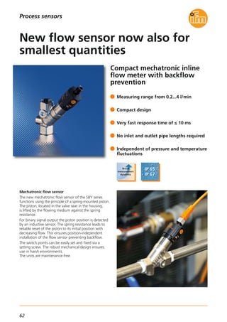
![63
(11.2015)
Flow sensors / flow meters
For further technical details please visit: www.ifm.com
Current consumption [mA] < 15
Ambient temperature [°C] 0...60
Protection rating, protection class IP 65 / IP 67, III
Housing materials
Brass
chemically nickel-plated;
anodised aluminium;
PA
Materials in contact
with the medium
High-grade stainless steel
(301/1.4310);
high-grade stainless steel
(316/1.4401);
PBT; brass chemically
nickel-plated; PPS;
O-ring: FKM Polyolefin
Short-circuit protection •
Further technical data
Overload protection •
L+
L
BN1
4 BK
3 BU
Wiring
Process
connection
Pressure
resistance
[bar]
Measuring range
[l/min]
Response time
[ms]
Order
no.
M12 connector · electrical design DC PNP
Rp 1/2 800.2...4 ≤ 10 SBY321
Operating voltage
[V]
24 DC
Type
Connection technology
Type Description Order
no.
M12 socket,
2 m black, PUR cable
EVC001
M12 socket,
5 m black, PUR cable
EVC002
M12 socket,
2 m black, PUR cable
EVC004
M12 socket,
5 m black, PUR cable
EVC005
M12 socket,
2 m orange, PVC cable
EVT064
M12 socket,
5 m orange, PVC cable
EVT001
Process sensors
Connection M12 connector
M12
94...99
27
Rp½
Rp½
66,5
18
107...113
13 13
Dimensions](https://image.slidesharecdn.com/ifm-innovations-topproducts-2015-2016-gb-160202102146/85/Innovations-2015-2016-64-320.jpg)
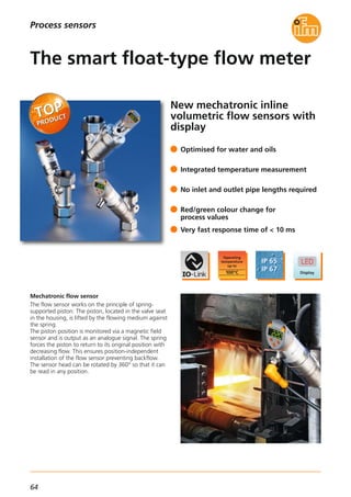
![65
(04.2015)
Flow sensors / flow meters
For further technical details please visit: www.ifm.com
Common technical data
Operating voltage [V DC] 18...30
Current consumption [mA] < 50
Accuracy flow measurement
± (4 % MV
+ 1 % VMR)
Output 1
IO-Link,
switching output,
frequency output
flow / temperature
Output 2
Switching output flow,
analogue output
4...20 mA flow
or temperature
Accuracy temperature monitoring ± 3 K
Type
SBY, SBG
Protection rating, protection class IP 65 / IP 67, III
BN
WH
BK
BU
4
1
3
2
OUT2
L+
L
OUT1
Wiring diagram
Measuring range
[l/min]
Response time
[ms]
Medium temperature
[°C]
Max.
operating pressure
[bar]
Order
no.
M12 connector · electrical design DC PNP / NPN
< 10-10...100 40 SBY232
Process connection
Rp 3/4
< 10-10...100 40 SBY233Rp 3/4
< 10-10...100 40 SBY234Rp 3/4
< 10-10...100 25 SBY246Rp 1
Type
< 10-10...100 25 SBY257Rp 1 1/2
< 10-10...100 40 SBG232G 1/2
< 10-10...100 40 SBG233G 1/2
< 10-10...100 40 SBG234G 1/2
< 10-10...100 25 SBG246G 3/4
< 10-10...100 25 SBG257G 1 1/4
Connection technology
Type Description Order
no.
Socket, M12,
2 m black, PUR cable
EVC001
Socket, M12,
5 m black, PUR cable
EVC002
Socket, M12,
2 m orange, PVC cable
EVT064
Socket, M12,
5 m orange, PVC cable
EVT001
Process sensors
Socket, M12,
2 m black, PUR cable
EVC004
Socket, M12,
5 m black, PUR cable
EVC005
0.3...15
0.5...25
1.0...50
2.0...100
4.0...200
0.3...15
0.5...25
1.0...50
2.0...100
4.0...200
IO-Link interface, current consumption
from USB port
E30396
Accessories
Type Description Order
no.](https://image.slidesharecdn.com/ifm-innovations-topproducts-2015-2016-gb-160202102146/85/Innovations-2015-2016-66-320.jpg)

![67
(11.2015)
Level sensors
Process
connection
Installation
length
[mm]
Approval Protection
[hazardous areas]*
Order
no.
Application: liquids, viscous media and powders
M12 connection · output function 2 x NO/NC programmable · 4-wire DC PNP · IO-Link 1.1
Medium temperature
oils, oil-based media,
powder
G 1/2 12 EHEDG, FDA -20...85 °C IP 67 / III LMT01A
G 1/2 153 EHEDG, FDA -20...85 °C IP 67 / III LMT03A
G 1/2 253 EHEDG, FDA -20...85 °C IP 67 / III LMT04A
Accessories
Type Description
High-grade stainless steel
Order
no.
Current rating [mA] 100
Housing materials
high-grade stainless steel
(1.4404 / 316L),
(1.4571 / 316Ti),
PEEK; PEI; FKM
Materials in contact
with the medium
high-grade stainless steel
(1.4404 / 316L),
(1.4571 / 316Ti),
PEEK; FKM
Shock resistance [g] 50
Vibration resistance [g]
(LMT03A, LMT04A)
8
Vibration resistance [g]
(LMT01A)
20
Ambient temperature [°C] -20...60
EMC (LMT03A, LMT04A)
Closed tanks
EN 61000-6-2
EN 61000-6-4
EMC (LMT01A)
Open tanks
Closed tanks
EN 61000-6-2
EN 61000-6-4
EN 61000-6-3
Operating voltage [V] 18...30 DC
Current consumption [mA] < 50
Further technical data
Clamp adapter
G 1/2 female – Clamp 1“–1.5“
E33401
Clamp adapter
G 1/2 female – Clamp 2“
E33402
Welding adapter ball, G 1/2 E30055
Welding adapter collar, G 1/2 E30056
Welding adapter,
cylindrical, for tanks, G 1/2
E43300
Welding adapter,
cylindrical, for pipes, G 1/2
E43301
Screw-in adapter
G1/2 female – G 3/4 male
E43302
Screw-in adapter
G1/2 female – G 1 male
E43303
Screw-in adapter
G1/2 female – 3/4 NPT
E43313
Clamp adapter,
G 1/2 female – Varivent D50
E43306
Clamp adapter,
G 1/2 female – Varivent D68
E43307
Accessories
Type Description Order
no.
IO-Link interface for parameter setting
and analysis of units with
DTM specification, current consumption
from USB port: max. 500 mA
E30396
Memory plug, parameter memory
for IO-Link sensors
E30398
T-piece, DN 25 E43316
T-piece, DN 40 E43317
T-piece, DN 50 E43318
For further technical details please visit: www.ifm.com
Welding adapter, long design
for deeper installation, G 1/2
E43319
Process sensors
ATEX approval
group II,
category 3D / 3G
Communication interface IO-Link 1.1
Connection M12 connector
LINERECORDER SENSOR,
Software for parameter setting and
setting up IO-Link sensors
QA0001
USB IO-Link master for parameter setting
and analysis of units
Supported communication protocols:
IO-Link (4.8, 38.4 and 230 Kbits/s)
E30390
*IP 68, IP 69K outside the hazardous area
Connection technology
Type Description Order
no.
Socket, M12,
2 m black, PUR cable
EVC04A
Socket, M12,
5 m black, PUR cable
EVC05A
Socket, M12,
10 m black, PUR cable
EVC06A](https://image.slidesharecdn.com/ifm-innovations-topproducts-2015-2016-gb-160202102146/85/Innovations-2015-2016-68-320.jpg)

![69
(11.2015)
Level sensors
Protection rating/
protection class
Max.
tank pressure
[bar]
-1...4 IP 68, IP 69K / III
Accessories (to be ordered separately)
Type Description Order
no.
For further technical details please visit: www.ifm.com
Process sensors
Process connection Medium temperature
[°C]
Order
no.
M12 connector · IO-Link 1.1
G 3/4 -20...100 LR2050
Current consumption [mA]
Dielectric constant medium
Ambient temperature [°C]
Metals in contact
with the medium
Housing materials
Power-on delay time [s]
Operating voltage [V] 18...30 DC
Current rating [mA] 200
Further technical data
IO-Link device type of transmission
Rods stainless steel (303 / 1.4305)
Coaxial pipes stainless steel (303 / 1.4305)
Flange plates stainless steel (303 / 1.4305)
Application: aqueous media, coolants, cleaning agents, oils. *
Flange plate, LR 73-90 E43201
Flange plate, LR 73 - 90 / NPT E43206
Flange plate, LR 65-80 E43202
E43203240 mm
E43204450 mm
E43226300 mm
E43205700 mm
E43227500 mm
E432071000 mm
E432081200 mm
E432091400 mm
E432101600 mm * A coaxial pipe is required for the unit to function correctly in low
dielectric media.
E43211240 mm
E43212450 mm
E43213700 mm
E432141000 mm
E432151200 mm
E432161400 mm
E432171600 mm
E43228300 mm
E43229500 mm
G 3/4
Connection technology
Type Description Order
no.
Socket, M12, 4-pole
2 m black, PUR cable
EVC004
Socket, M12, 4-pole
5 m black, PUR cable
EVC005
Socket, M12, 4-pole
2 m black, PUR cable, LED
EVC007
Socket, M12, 4-pole
5 m black, PUR cable, LED
EVC008
IO-Link interface for parameter setting
and analysis of units with
DTM specification, current consumption
from USB port: max. 500 mA
E30396
Memory plug, parameter memory
for IO-Link sensors
E30398
LINERECORDER SENSOR,
software for parameter setting and
setting up IO-Link sensors
QA0001
IO-Link accessories
Type Description Order
no.
< 50
1.8...5*
> 5
-40...80
high-grade stainless steel
(316L / 1.4404,
316S12 / 14435),
PTFE, FKM
high-grade stainless steel
(316L / 1.4404),
PEI, PBT, PTFE, FKM
≤ 3
1.1
E43351210 mm
E43352265 mm
E433532000 mm
Coaxial pipes, slotted stainless steel (304S15 / 1.4301)
700 mm E43333
1200 mm E43334
E43354210 mm
E43355265 mm
E433562000 mm
E43218450 mm
E43219700 mm
E432201000 mm
E432211600 mm
3/4" NPT](https://image.slidesharecdn.com/ifm-innovations-topproducts-2015-2016-gb-160202102146/85/Innovations-2015-2016-70-320.jpg)

![71
(04.2015)
Level sensors
Process connection Installation length
[mm]
Medium temperature
oils, fats, bulk materials
[°C]*
Order
no.
Medium: Aqueous media · Can be set to other media using IO-Link 1.1
M12 connector · 4-wire DC PNP
Medium temperature
water-based media
[°C]
G 1/2 12 0...85 0...100 LMT191
G 1/2 153 0...85 0...100 LMT194
G 1 38 0...85 0...100 LMT392
G 3/4 28 0...85 0...100 LMT292
G 1/2 38 0...85 0...100 LMT192
G 1/2 253 0...85 0...100 LMT195
Accessories
Type Description
High-grade stainless steel
Order
no.
Max. medium temperature [°C]
(WHG)
100
Housing materials
PEEK;
high-grade stainless steel
(316L/1.4404),
PA12, FPM
Protection IP 68 / IP 69K, III
Materials in contact
with the medium
PEEK;
high-grade stainless steel
(316L/1.4404), FPM
Shock resistance [g] 50
Vibration resistance [g] 20
Max. ambient temperature [°C]
(WHG)
0...85
EMC
Closed tanks:
Open tanks:
EN 6100-6-2:2005
EN 6100-6-3:2006
EN 6100-6-4:2006
Operating voltage [V] 18...30 DC
Current rating [mA] 100
Further technical data
Clamp adapter,
G 1/2 female – Clamp 1"–1.5"
E33401
Clamp adapter,
G 1/2 female – Clamp 2"
E33402
Welding adapter ball, G 1/2 E30055
Welding adapter collar, G 1/2 E30056
Welding adapter,
cylindrical, for tanks, G 1/2
E43300
Welding adapter,
cylindrical, for pipes, G 1/2
E43301
Screw-in adapter,
G 1/2 female – G 3/4 male
E43302
Screw-in adapter,
G 1/2 female – G 1 male
E43303
Screw-in adapter,
G 1/2 female – 3/4 NPT
E43313
Accessories
Type Description Order
no.
IO-Link interface for parameter setting
and analysis of units with
DTM specification, current consumption
from USB port: max. 500 mA
E30396
For further technical details please visit: www.ifm.com
Welding mandrel, G 1/2 E43314
Sealing plug, G 1/2 E43308
Welding adapter, long design
for deeper installation, G 1/2
E43319
Process sensors
LINERECORDER SENSOR,
software for parameter setting and
setting up IO-Link sensors
QA0001
* For operation to WHG](https://image.slidesharecdn.com/ifm-innovations-topproducts-2015-2016-gb-160202102146/85/Innovations-2015-2016-72-320.jpg)
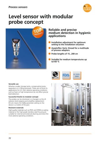
![73
(04.2015)
Level sensors
Protection rating/
protection class
Max.
tank pressure
[bar]
-1...40 IP 69K, III
Accessories
Type Description Order
no.
0.15 m,
high-grade stainless steel (316L/1.4404)
E43345
0.3 m,
high-grade stainless steel (316L/1.4404)
E43346
0.5 m,
high-grade stainless steel (316L/1.4404)
E43340
0.7 m,
high-grade stainless steel (316L/1.4404)
E43347
1.0 m,
high-grade stainless steel (316L/1.4404)
E43341
1.5 m,
high-grade stainless steel (316L/1.4404)
E43348
2.0 m,
high-grade stainless steel (316L/1.4404)
E43342
IO-Link interface for parameter setting
and analysis of units with
DTM specification, current consumption
from USB port: max. 500 mA
E30396
Memory plug, parameter memory
for IO-Link sensors
E30398
For further technical details please visit: www.ifm.com
Process sensors
LINERECORDER SENSOR,
software for parameter setting and
setting up IO-Link sensors
QA0001
Process connection Medium temperature
[°C]
Order
no.
M12 connector · IO-Link 1.1
Aseptoflex Vario -40...150 LR2750
Current consumption [mA] < 80
Dielectric constant medium > 5
Ambient temperature [°C] -40...80
Metals in contact
with the medium
high-grade stainless steel
(316L/1.4404),
PEEK, EPDM
Housing materials
high-grade stainless steel
(316L/1.4404),
PEI, PFA, PBT, FKM
Power-on delay time [s] ≤ 3
Operating voltage [V] 18...30 DC
Current rating [mA] 200
Further technical data
IO-Link device type of transmission 1.1
Probes for hygienic LR processes
Pipe fitting,
DN40 (1.5")
E33212
Clamp adapter,
Clamp 2"
E33202
Pipe fitting,
DN50 (2")
E33213
Clamp adapter,
Clamp 1-1.5"
E33201
Aseptoflex Vario adapter
IO-Link
Connection technology
Type Description Order
no.
Socket, M12, 4-pole,
5 m orange, PVC cable
EVT001
Socket, M12, 4-pole,
2 m orange, PVC cable
EVT064
Socket, M12, 4-pole,
5 m orange, PVC cable
EVT004
Socket, M12, 4-pole,
2 m orange, PVC cable
EVT067
Welding adapter,
Ø 50 mm
E30122](https://image.slidesharecdn.com/ifm-innovations-topproducts-2015-2016-gb-160202102146/85/Innovations-2015-2016-74-320.jpg)
![75
(04.2015)
Level sensors
Accessories (to be ordered separately)
Type Description
Stainless steel (303/1.4305)
Order
no.
For further technical details please visit: www.ifm.com
Process sensors
Rods stainless steel (303 / 1.4305)
Coaxial pipes stainless steel (303 / 1.4305)
Flange plates
Connection technology
Applications: aqueous media, coolants, cleaning agents, oils. *
Type Description Order
no.
Socket, M12, 4-pole
2 m black, PUR cable
EVC004
Socket, M12, 4-pole
5 m black, PUR cable
EVC005
Socket, M12, 4-pole
2 m black, PUR cable, LED
EVC007
Socket, M12, 4-pole
5 m black, PUR cable, LED
EVC008
Socket, M12, 8-pole
2 m black, PUR cable
E11231
Socket, M12, 8-pole
5 m black, PUR cable
E11232Flange plate, LR 73-90 E43201
Flange plate, LR 73 - 90 / NPT E43206
Flange plate, LR 65-80 E43202
E43203240 mm
E43204450 mm
E43226300 mm
E43205700 mm
E43227500 mm
E432071000 mm
E432081200 mm
E432091400 mm
E432101600 mm
E43211240 mm
E43212450 mm
E43213700 mm
E432141000 mm
E432151200 mm
E432161400 mm
E432171600 mm
E43218450 mm
E43228300 mm
E43219700 mm
E43229500 mm
E432201000 mm
E432211600 mm
* A coaxial pipe is required for the unit to function correctly in low
dielectric media.
Process connection Set point
accuracy
[cm]
Repeatability
[cm]
Max.
tank pressure
[bar]
Protection rating/
protection class
Order
no.
M12-connector
Output function 1 x IO-Link / 1 x analogue 4...20 mA / 0...10 V · 4-wire DC PNP
G 3/4 ± 1.5 ± 0.5 -1...4 IP 69K, III LR9020
Current consumption [mA] < 80
Dielectric constant medium
2...20*
> 20
Ambient temperature [°C] 0...60
Medium temperature [°C] 0...80 / (90 peak)
Metals in contact
with the medium
stainless steel
(303/1.4305), PTFE, NBR
Housing materials
FKM, NBR, PBT, PC, TPE-V,
stainless steel
(1.4301/304), PTFE, PEI
Power-on delay time [s] 3
Operating voltage [V] 18...30 DC
Current rating [mA] 200
Further technical data
IO-Link device type of transmission COM2 (38.4 kbaud)
G 3/4
3/4" NPT](https://image.slidesharecdn.com/ifm-innovations-topproducts-2015-2016-gb-160202102146/85/Innovations-2015-2016-76-320.jpg)

![77
(11.2015)
Temperature sensors
For further technical details please visit: www.ifm.com
Process sensors
Dimensions
64
48
M12x1
34
104
3
16,5
2
1
30
Connection technology
Type Description Order
no.
Socket, M12,
2 m black, PUR cable
EVC001
Socket, M12,
5 m black, PUR cable
EVC002
Socket, M12,
2 m black, PUR cable
EVC004
Socket, M12,
5 m black, PUR cable
EVC005
Mounting clamp, Ø 34 mm,
PBT
E10017
Mounting clamp, Ø 34 mm,
PA
E10193
Protective cover for fluid sensors with
M12 connector,
polypropylene homopolymer
E30420
Accessories
Type Description Order
no.
Response dynamics
T05 / T09
[s]
Pressure resistance
[bar]
depends on the connected sensor
Measuring range
[°C]
Factory setting
[°C]
Order
no.
Output function 1 x NO / NC programmable · 1 x analogue output 4…20 mA or 0…10 V programmable
-100...600 -40...300
Process connection
G 1/2 A TR2439
depends on the connected sensor
Output function 2 x NO / NC programmable
-100...600 -40...300 G 1/2 A TR7439
Accuracy [K] ± 0,3 + (± 0,1 % MS)
Electrical design PNP / NPN
Protection IP 67
Communication interface IO-Link
Resolution display [K] 0,1
Operating voltage [V] 18...32 DC
Current rating [mA] 250
Further technical data
IO-Link accessories
Type Description Order
no.
Temperature sensors for connection
to the TR type
Version
High-temperature cable sensor
Order
no.
2 m,
PFA / PTFE cables
TS2451
2 m,
PFA / PTFE cables
TS2452
2 m,
PFA / PTFE cables
TS2453
2 m,
PFA / PTFE cables
TS2454
IO-Link interface for parameter setting
and analysis of units with
DTM specification, current consumption
from USB port: max. 500 mA
E30396
Memory plug, parameter memory
for IO-Link sensors
E30398
LINERECORDER SENSOR,
software for parameter setting and
setting up IO-Link sensors
QA0001
USB IO-Link master for parameter setting
and analysis of units
Supported communication protocols:
IO-Link (4.8, 38.4 and 230 Kbits/s)
E30390
Installation
length
[mm]
100
150
200
250
1) LEDs (display unit / switching status)
2) 4-digit alphanumeric display / alternating indication of red and green
3) Programming buttons](https://image.slidesharecdn.com/ifm-innovations-topproducts-2015-2016-gb-160202102146/85/Innovations-2015-2016-78-320.jpg)
![79
(11.2015)
Temperature sensors
Dimensions
34
140
4
3
1445
2
1 10048
M12x1
30
6
22
For further technical details please visit: www.ifm.com
Process sensors
Connection technology
Type Description Order
no.
Socket, M12,
2 m black, PUR cable
EVC001
Socket, M12,
5 m black, PUR cable
EVC002
Socket, M12,
2 m black, PUR cable
EVC004
Socket, M12,
5 m black, PUR cable
EVC005
Mounting clamp Ø 34 mm,
PBT
E10017
Mounting clamp Ø 34 mm,
PA
E10193
Progressive ring T-piece
Stainless steel (320S17)
E40102
Adapter, M18 x 1.5 - L18, high-grade
stainless steel (316L/1.4404), FKM
E40104
Adapter, M18 x 1.5 - G 1/2
High-grade stainless steel (316L/1.4404)
E40096
Adapter, M18 x 1.5 - G 1/4
High-grade stainless steel (316L/1.4404)
E40099
Protective cover for fluid sensors with
M12 connector,
polypropylene homopolymer
E30420
Accessories
Type Description Order
no.
Response dynamics
T05 / T09
[s]
Pressure resistance
[bar]
300 1 / 3
Measuring range
[°C]
Factory setting
[°C]
Order
no.
Output function 1 x NO / NC programmable · 1 x analogue output 4…20 mA or 0…10 V programmable
-50...150 -40...150
Process connection
M18 x 1.5 I TN2511
300 1 / 3
Output function 2 x NO / NC programmable
-50...150 -40...150 M18 x 1.5 I TN7511
Accuracy [K] ± 0.3 + (± 0.1 % MS)
Electrical design PNP / NPN
Protection IP 67
Communication interface IO-Link
Resolution display [K] 0.1
Operating voltage [V] 18...32 DC
Current rating [mA] 250
Further technical data
IO-Link interface for parameter setting
and analysis of units with
DTM specification, current consumption
from USB port: max. 500 mA
E30396
Memory plug, parameter memory
for IO-Link sensors
E30398
LINERECORDER SENSOR,
software for parameter setting and
setting up IO-Link sensors
QA0001
IO-Link accessories
Type Description Order
no.
USB IO-Link master for parameter setting
and analysis of units
Supported communication protocols:
IO-Link (4.8, 38.4 and 230 Kbits/s)
E30390
1) LEDs (display unit / switching status), 2) 4-digit alphanumeric
display / alternating indication of red and green, 3) Programming
buttons, 4) Upper part of the housing can be rotated by 345°](https://image.slidesharecdn.com/ifm-innovations-topproducts-2015-2016-gb-160202102146/85/Innovations-2015-2016-80-320.jpg)

![81
(04.2015)
Process sensors
For further technical details please visit: www.ifm.com
Temperature sensors
Installation length
[mm]
Order
no.
Process connection Clamp 3/4“
Temperature range (scaled 4...20 mA) -50...200 °C
Process connection Clamp 1.5“
Temperature range (scaled 4...20 mA) -50...200 °C
Operating voltage [V DC] 18...32
Protection IP 67, IP 68, IP 69K / lll
Materials in contact
with the medium
High-grade stainless steel
(316L/1.4404)
Further technical data
Reverse polarity / overload protection • / •
Measuring element Pt1000, class A
Response dynamics T05 / T09 < 0.5 s / < 2 s
Accuracy [K] ± 0.3 + (± 0.1 % MS)
Measuring range [°C] -50...200
Ambient temperature [°C] -25...80
IO-Link revision 1.1
IO-Link interface for parameter setting
and analysis of units with
DTM specification, current consumption
from USB port: max. 500 mA
E30396
Memory plug, parameter memory
for IO-Link sensors
E30398
LINERECORDER SENSOR,
software for parameter setting and
setting up IO-Link sensors
QA0001
Accessories
Type Description Order
no.
Dimensions
6
M12x1
18,7
15,9 50,4 EL
LED 2 x 180° 1
L+
L
3
1
4
2
IO-Link
L+
L
1
2
Wiring diagram
Example TA2002
Connection technology
Type Description Order
no.
TA2002
TA2012
TA2802
TA2812
TA2832
TA2842
G 1/2 process connection with sealing cone
Temperature range (scaled 4...20 mA) -50...200 °C
TA2502
TA2512
TA2532
TA2542
Process connection ø 6 mm
Temperature range (scaled 4...20 mA) -50...200 °C
TA2212
TA2232
TA2242
1) 3/4" Clamp
Socket, M12, 4-pole,
5 m orange, PVC cable
EVT001
Socket, M12, 4-pole,
10 m orange, PVC cable
EVT002
Socket, M12, 4-pole,
5 m orange, PVC cable
EVT004
Socket, M12, 4-pole,
10 m orange, PVC cable
EVT005
25
60
30
50
100
150
30
50
100
150
50
100
150](https://image.slidesharecdn.com/ifm-innovations-topproducts-2015-2016-gb-160202102146/85/Innovations-2015-2016-82-320.jpg)
![83
(11.2014)
Process sensors
For further technical details please visit: www.ifm.com
Temperature sensors
Operating voltage [V DC] 18...32
Protection IP 67, IP 68, IP 69K / lll
Materials (wetted parts)
high-grade stainless steel
(316L/1.4404)
Further technical data
Reverse polarity / overload protection • / •
Measuring element Pt1000, class A
Response dynamics T05 / T09 1 s / 3 s
Accuracy [K] ± 0.3 + (± 0.1 % MS)
Measuring range [°C] -50...150
Ambient temperature [°C] -25...80
IO-Link revision 1.1
IO-Link interface for parameter setting
and analysis of units with DTM
specification, current consumption
via USB port: max. 500 mA
E30396
Memory plug, parameter memory for
IO-Link sensors
E30398
LINERECORDER SENSOR,
software for parameter setting and
set-up of IO-Link sensors
QA0001
Accessories
Type Description Order
no.
Dimensions
Wiring diagram
Connection technology
Type Description Order
no.
Socket, M12,
2 m black, PUR cable
EVC001
Socket, M12,
5 m black, PUR cable
EVC002
Socket, M12,
2 m black, PUR cable
EVC004
Socket, M12,
5 m black, PUR cable
EVC005
6
M12x1
18,7
15,9 48 14
26LED G ½
EL
L+
L
3
1
4
2
IO-Link
L+
L
1
2
TA24
6
M12x1
18,7
15,9 48
19
13
G ¼LED
EL
TA21
Nominal length
[mm]
Order no.
Factory setting
Pressure resistance
[bar]
Process connection G 1/2
Analogue output scalable 4...20 mA
30 300
50 300
100 160
150 160
Process connection G 1/4
Analogue output scalable 4...20 mA
25 400
50 400
100 160
150 160
TA2405
TA2415
TA2435
TA2445
TA2105
TA2115
TA2135
TA2145
Thermowells
G 1/2 E37600
G 1/2 E37610
G 1/2 E37620
G 1/2 E37640
27
74
124
224
50
100
150
250
Screw-in thermowell, process connection G 1/2
-50...150 °C
-50...150 °C
Process connection G 1/2
Analogue output scalable 4...20 mA
50 300
100 160
150 160
TA2417
TA2437
TA2447
0...100 °C
27
G ½
G ½
28 EL
BL
1
9
7
Dimensions
Device
connection
Installation depth EL [mm]
Sensor Thermowell
Order
no.](https://image.slidesharecdn.com/ifm-innovations-topproducts-2015-2016-gb-160202102146/85/Innovations-2015-2016-84-320.jpg)

![85
(11.2014)
Process sensors
For further technical details please visit: www.ifm.com
Temperature sensors
Device
connection
Installation depth EL [mm]
Sensor Thermowell
G 1/2 E37810100
G 1/2 E37820150
G 1/2 E37830250
G 1/2 E37850350
Order
no.
G 1/2 E37910
G 1/2 E37920
G 1/2 E37930
G 1/2 E37950
G 1/2 E37430250
G 1/2 E37450350
Ø 6 mm E37603
Ø 6 mm E37613
Ø 6 mm E37623
Ø 6 mm E37643
Ø 6 mm E37663
G 1/2 conical E37511
G 1/2 conical E37521
G 1/2 conical E37411
G 1/2 conical E37421
G 1/2 conical E37431
G 1/2 E37600
G 1/2 E37610
G 1/2 E37620
G 1/2 E37640
64
115
191
267
191
267
33
83
128
233
333
68
118
49
99
149
27
74
124
224
50
100
150
250
350
100
150
50
100
150
50
100
150
250
Process connection Tri-Clamp 1.5" for type: TA24, TT12, TT32, TM44, TD22
Process connection Tri-Clamp 2" for type: TA24, TT12, TT32, TM44, TD22
Welding thermowell, weld-in process connection for type: TT32, TD22
Clamp fitting, process connection G 1/2 for type: TT92, TT02, TT12, TT22, TT32, TD22
Hygienic thermowell, process connection G 1/2 conical for type: TM45, TD25
Welding clamp adapter, ball process connection 34 mm Ø for type: TM45, TD25
Screw-in thermowell, process connection G 1/2 for type: TA24, TT02, TT12, TT22, TT32, TM44, TD22
63
EL
BL
6,4
44,5
12,7
6,6
19
38,1 1
26,7
½" NPS
63
EL
BL
6,4
44,5
12,7
6,6
19
38,1
1
26,7
½" NPS
38,1
44,5 EL
BL
6,4
6,6
16
½" NPS
7
9
27 G ½
EL
BL
13
1M4
27
G ½
G ½
9
7
18
72 EL
BL
2,5
37
2,5
41 EL
BL
G ½
7
9
30
34
16,6
27
G ½
G ½
28 EL
BL
1
9
7
1) 1.5" Clamp (ISO 2852)
1) 2" Tri-Clamp (ISO 2852)
100
150
250
350
64
115
191
267](https://image.slidesharecdn.com/ifm-innovations-topproducts-2015-2016-gb-160202102146/85/Innovations-2015-2016-86-320.jpg)


![89
(11.2015)
The products
Order
no.
Advantages and customer’s benefits
Fail-safe sensors with a current consumption below
200 mA can be operated on AC507S without auxiliary
voltage. Connection is only made via the yellow AS-i
flat cable.
AS-i quick connection
The quick-connection technology provides a high degree
of installation reliability and flexibility. The AS-i flat cable
can be connected from three different directions.
Diagnosis on site
The LEDs indicate the status of the inputs and outputs
and the communication.
Safety
The module meets the requirements up to SIL3 according
to EN 62061 and PL e to EN 13849-1. In the event of a
fault, the integrated communication monitoring switches
the signal outputs off.
Applications
The module is designed for the connection of electro-
sensitive protective equipment (ESPE) with electronic
outputs to EN 61496-1. It is particularly suited for the
connection of safe inductive sensors such as GM705S.
Pulse pick-ups for the display of muting functions can
be connected via M12 sockets.
Operating voltage (AS-i) [V DC] 26.5...31.6
Short-circuit protection •
Overload protection •
AS-i profile S-7.B.E
AS-i specification 2.11 + 3.0
Extended addressing mode –
Ambient temperature [°C] -25...55
Protection IP 67
Safe AS-i input modules
AC507S, AC508S
Technical data
Type Description Order
no.
Safe AS-i input module
Sensor supply
Inputs / outputs: via AS-i
Current rating inputs / outputs:
200 mA in total
Total current consumption: ≤ 280 mA
AC507S
Sensor supply
Inputs / outputs: 24 V external, PELV
Current rating inputs / outputs:
inputs 200 mA, outputs 500 mA
Total current consumption: < 80 mA
AC508S
AS-Interface Safety at Work
For further technical details please visit: www.ifm.com
Dimensions
45
103
40,2
44,7
25,8
Industrial communication
Adapter cable,
from 8 poles to 5 poles,
M12 plug / M12 socket,
configured for automatic operation
EY3090
Adapter cable,
5 poles,
M12 plug / M12 socket,
configured for "short range"
EY3092
Adapter cable](https://image.slidesharecdn.com/ifm-innovations-topproducts-2015-2016-gb-160202102146/85/Innovations-2015-2016-90-320.jpg)

![91
(04.2015)
The products
Fieldbus,
PROFINET
AL1000
Fieldbus,
PROFIBUS
AL1010
Fieldbus,
EtherNet/IP
AL1020
Fieldbus,
EtherCAT
AL1030
Total current consumption [A] 12
Operating voltage [V DC] 18...31.2
IO-Link version 1.1
Number of IO-Link ports 8
Number of binary inputs
4 + 8
(IO-Link in SIO mode)
Ambient temperature [°C] -25...60
Housing material
PA;
Socket:
Nickel-plated brass
Protection IP 65, IP 67
Parameter memory •
Port A /port B 4 / 4
IO-Link master field modules
IO-Link components
Industrial communication
Technical data
Unit versions
For further technical details please visit: www.ifm.com
Advantages and customer benefits
• 12 amperes on an M12 connector
The module supply and the auxiliary power are supplied
via the T-coded M12 connector. The energy can be
looped through the module (daisy chain).
• Easy sensor connection
The sensors and actuators are connected via standard
M12 connection cables without screening.
The cable may be up to 20 m long.
• Reliable digital data
The sensor data is transferred digitally. Contact
resistance and EMC interference cannot falsify the
signals.
Dimensions
Order
no.
Type Description
20
30,5
1,5
M12x1
LEDs
60
30
198,5
185
212
8,5
6
AL1000](https://image.slidesharecdn.com/ifm-innovations-topproducts-2015-2016-gb-160202102146/85/Innovations-2015-2016-92-320.jpg)
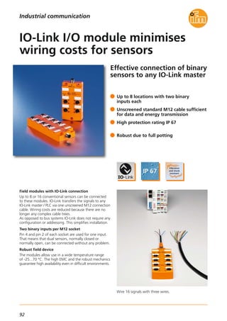
![93
(04.2015)
Dimensions
IO-Link version 1.1 and 1.0
Operating voltage [V DC] 18...30
Type of transmission COM2 (38 kBaud)
Ambient temperature [°C] -25...70
Short-circuit protection •
Overload protection •
Protection IP 67
Min. cycle time process data [ms] 2.3
IO-Link input modules
IO-Link components
Industrial communication
Technical data
For further technical details please visit: www.ifm.com
Advantages and customer benefits
• IO-Link replaces multi-pole cable
Multi-wire cables and connectors are a matter of
the past. Standard M12 connections between the
input module and an IO-Link master transfer up to
16 binary input signals.
• Support of interchangeable tools
The tree-wire connection minimises complex cabling
for interchangeable tools.
The input modules can store a tool number so that
the PLC can easily identify and differentiate tools.
M12 sockets 4
Number of binary inputs 4 x 2
Total current consumption [mA] ≤ 450
8
8 x 2
≤ 850
Current rating [mA]
for all inputs, total
400 800
Unit versions
Order no. AL2400 AL2401
23
27
54,5
M12x1
M12x1
X1.0
4,7107
118,2
28,5
39
7,5
60
X1.1
X1.2 X1.3
AL2400
23
27
4,7107
152
28,5
39
7,5
60
54,5
M12x1
M12x1
X1.0 X1.1
X1.2 X1.3
X1.4 X1.5
X1.6 X1.7
AL2401](https://image.slidesharecdn.com/ifm-innovations-topproducts-2015-2016-gb-160202102146/85/Innovations-2015-2016-94-320.jpg)

![95
(04.2015)
System solutions
Industrial communication
For further technical details please visit: www.ifm.com
Special features
Ethernet interface for PLC connection
This IO-Link master operates as an input/output card
with a total of 20 I/Os, of which 8 are for IO-Link devices
and the rest for binary signals.
All signals can be easily transmitted to compatible
controllers via the standard fieldbuses EtherNet/IP or
Profinet.
Two ways simultaneously = PLC and server in
parallel
So far, all sensor signals had to be sent by the PLC
to higher-level systems. This is now done via a parallel
communication path (Y path). The PLC program
remains unchanged.
Integrated web server for configuration and
diagnostics
No special software is required for configuration.
All IO-Link settings can be made via the integrated
web interface. To do so, a standard PC with Ethernet
connection and web browser is required.
Convenient IODD integration
Via the web interface, up to 8 different IODDs (IO-Link
device descriptions) can be loaded into the master. After
connection of the IO-Link devices, the corresponding
IODDs are automatically assigned to the connected
IO-Link devices and the corresponding ports.
Parallel sensor communication
IO-Link master IO-Link master
PLC
industrial fieldbus
LR agent communication (option)
LINERECORDER
web-based
user interface
IO-Link
sensors
···1 2 7 8
server
IO-Link
IO-Link
sensors
···1 2 7 8
Technical data
“Y“ path for PLC data exchange and a parallel
connection to the server via LINERECORDER AGENT
IO-Link master module for connection to fieldbuses
Fieldbus connection EtherNet/IP Profinet
Further protocols Modbus / TCP (slave)
Order no. AY1020 AY1000
Supply voltage [V] 18...30 DC
Current consumption [A] 2 (24 V)
IO-Link version 1.1
Number of IO-Link ports 8
Parameter memory •
IO-Link port A / port B up to 8, configurable
Inputs/outputs IO-Link / SIO configurable
IO-Link baud rates COM 1...3 4.8k, 38.4k, 230.4kBaud
Digital inputs max. DI 8 (16) +2
Digital outputs max. DO 8 + 2
IO-Link / DI / DO status LEDs 20
Ethernet connections 2x (10/100 BASE-Tx)
Module / Ethernet status LEDs 7
Ethernet sockets RJ45
Electrical connections screw terminals
Protection IP 20
Housing material polyamide plastics
Ambient temperature [°C] 0...70
Installation DIN rail](https://image.slidesharecdn.com/ifm-innovations-topproducts-2015-2016-gb-160202102146/85/Innovations-2015-2016-96-320.jpg)
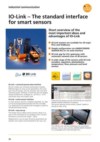
![97
(04.2015)
System solutions
Industrial communication
For further technical details please visit: www.ifm.com/gb/io-link
10 good reasons to use IO-Link
Fast and easy set-up and service:
1. Offline parameter setting of the sensors prior to
installation.
2. Automatic sensor detection online when using the
IO-Link app on the AS-i/fieldbus gateway.
3. Easy sensor replacement with automatic parameter
setting by the master.
Sensor identification included.
High machine uptime:
4. Avoidance of incorrect handling during operation
by deactivating the operating keys on the sensor.
5. Easy transmission of the measured values without
conversion losses; values on the sensor display
correspond to the values on the machine display.
6. Highly interference immune - because digital -
analogue value transmission in comparison with
conventional analogue technology. And this using
an unscreened cable without special grounding.
7. Machine diagnostics up to the sensor level
functions without disrupting the operation.
Less wiring saves installation costs:
8. Several analogue signals and switch points can be
transmitted using only one standard 3-wire cable.
This reduces the number of terminals and makes
space in the cable duct.
9. Sensors and actuators, analogue or binary, can be
connected via IO-Link ports. This replaces different
input/output modules.
Investment security:
10. IO-Link has been internationally standardised to
IEC 61131-9 and is therefore future-proof. The
acceptance of all leading automation suppliers
ensures investment security for OEMs and users.
IO-Link is the interface to Industry 4.0.
Typical plant configuration
IO-Link master
IP20
IO-Link master
IP67
sensor parameter settingPLC
industrial fieldbus
LINERECORDER
sensor 4.0
MODBUS-TCP
IO-Link
sensors
···1 2 7 8
IO-Link
sensor
with
IO-Link
IO-Link
IO-Link
sensors
···1 2 7 8
USB
adapter
Order data
Technical data
IO-Link service & maintenance tools
Characteristic IO-Link data
IO-Link USB master low power E30396
IO-Link USB master ext. power E30390
LR Sensor 4.0 parameter setting software
with IODD import
QA0001
Analogue converter -50...300 °C
Pt100/Pt1000 to IO-Link
TP3232
Analogue converter 0...100 °C
Pt100/Pt1000 to IO-Link
TP3237
IO-Link app for AS-i gateways AC14xx AP3001
Analogue converter -50...150 °C
Pt100/Pt1000 to IO-Link
TP3231
Memory plug - sensor-parameter memory E30398
Cable length [m] 20
Line physics type A
3-wire cable,
unscreened
Connection M12, M8, M5, terminals
Process data (PD) per device 1 bit ... 32 bytes
Cycle time for 2 bytes [ms] 2.3
Parameters, diagnostics and events acyclic transmission
Power supply type A
Power supply type B
sensors 200 mA
sensors + actuators
separated
M12 pin connection type A
pin 1: 24 V DC
pin 3: 0 V DC
pin 4: IO-Link /
binary input / output
Description Order
no.](https://image.slidesharecdn.com/ifm-innovations-topproducts-2015-2016-gb-160202102146/85/Innovations-2015-2016-98-320.jpg)

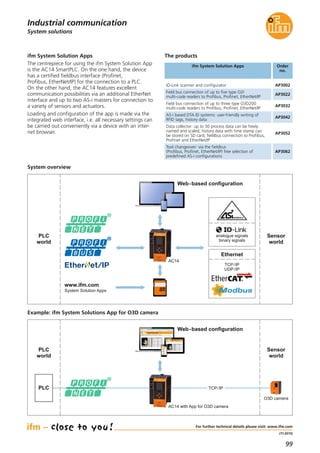
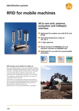
![101
(11.2015)
RFID 125 kHz / RFID 13.56 MHz
When competences complement each other
ifm develops and produces RFID evaluation units and
antennas for industrial applications.
These RFID systems are available for all common
frequency ranges.
Even the integration of different fieldbuses into the
RFID components has been successfully implemented.
Furthermore, ifm as an automation specialist has know-
how of many years in the area of mobile machines,
where control systems and sensors from ifm have been
established in the market.
The competences and experience of these both different
areas have now been combined in the RFID solution for
mobile machines.
For further technical details please visit: www.ifm.com
Identification systems
Description Order
no.
E80370
ID tag/30X2.8/03 – 13.56 MHz,
16 Kbits – FRAM
E80371ID tag/30X2.5/06 – 13.56 MHz, 896 bits
E80377
ID tag/R20X2.5/06 – 13.56 MHz,
896 bits
RFID evaluation unit / RFID antenna
The products
E80380ID tag/30X2.8/03 – 13.56 MHz, 64 Kbits
E80381
ID tag/4.35X3.6/03 – 13.56 MHz,
896 bits, 10 pcs
E80382
ID tag/label 65X30/03 – 13.56 MHz,
896 bits, 500 pcs
E80379
ID tag/label 80X50/03 – 13.56 MHz,
896 bits, 500 pcs
Further technical data
Operating voltage [V DC] 9...32
Current consumption sensor [mA]
< 50 at 24 V,
< 85 at 12 V
Ambient temperature [°C] -40...85
Protection rating,
protection class
IP 67 / IP 69K,
III
Housing material stainless steel
Interfaces 1 x CAN
Supported CAN protocols CANopen
Standards and tests
(extract)
CE,
radio approval
Connection M12 connectorJumper, M12,
5 m, black, PUR cable, LED
EVC039
Jumper, M12,
5 m, black, PUR cable
EVC069
Socket, M12,
2 m black, PUR cable
EVM036
Socket, M12,
10 m black, PUR cable
EVM038
Socket, M12,
5 m black, PUR cable
EVC492
RFID transponders
Accessories
BasicDisplay XL, 4,3",
CAN Interface
CR0452
Display
Connection technology
Type Description Order
no.
Type Description Order
no.
DTM424
M18 flush, 13.56 MHz,
CANopen interface
DTM425
M18 non flush, 13.56 MHz,
CANopen interface
DTM434
M30 flush, 13.56 MHz,
CANopen interface
DTM435
M30 non flush, 13.56 MHz,
CANopen interface
Process and dialogue unit PDM360 NG,
7" colour display
CR1081](https://image.slidesharecdn.com/ifm-innovations-topproducts-2015-2016-gb-160202102146/85/Innovations-2015-2016-102-320.jpg)
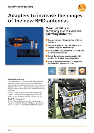
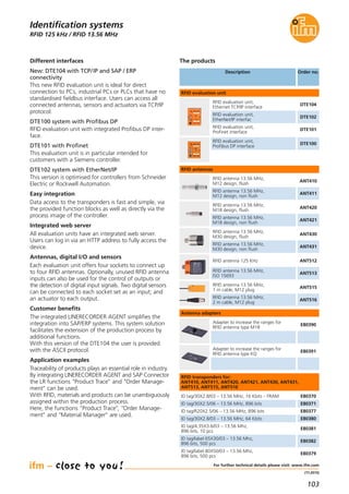

![105
(04.2015)
1D/2D code readers
Type of sensor:
CMOS image sensor, black/white,
VGA resolution 640 x 480
Readable 2D codes
ECC200, PDF-417, QR, Micro QR, Aztec
Readable 1D codes
Interleaved 2-of-5, Industrial 2-of-5, Code 39
Code 128, Pharmacode, Code 93, Codabar
EAN13, EAN13-Add-On 2, EAN13-Add-On 5
EAN8, EAN8-Add-On 2, EAN8-Add-On 5
UPC-A, UPC-A Add-On 2, UPC-A Add-On 5
UPC-E, UPC-E Add-On 2, UPC-E Add-On 5
GS1 DataBar Omnidirectional, GS1 DataBar Truncated
GS1 DataBar Stacked, GS1 DataBar Stacked Omni
GS1 DataBar Limited, GS1 DataBar Expanded
GS1 DataBar Expanded Stacked
Wide range of applications
The ifm multicode reader is used in a wide range of
industrial applications. It provides product tracking,
production control or product identification in the most
varied areas: automotive, electronic and food industries,
conveyor technology or in machine tools and printing
machines.
The standardised process interfaces RS-232, Ethernet
TCP/IP and EtherNet/IP ensure fast and easy integration
in industrial control technology.
Type Description Order
no.
Accessories
For further technical details please visit: www.ifm.com
Identification systems
Operating software for multicode reader E2I200
OPC server for multicode reader E2I210
High-grade stainless steel mounting set
for rod mounting, Ø 12 mm
E2D110
High-grade stainless steel mounting set
for rod mounting, Ø 14 mm
E2D112
Clamp,
high-grade stainless steel, Ø 12 mm
E21110
Clamp,
high-grade stainless steel, Ø 14 mm
E21109
Clamp linking ring,
high-grade stainless steel
E21076
Protective cover/diffuser E21165
Protective plastic cover E21166
Protective glass cover E21168
Laser protection pane E21169
Connection technology
Type Description Order
no.
Socket, M12,
2 m PUR cable, 8 poles
E11950
Socket, M12,
5 m, PUR cable, 8 poles
E11807
Ethernet, cross-over patch cable,
2 m, PUR cable, M12 / RJ45
E11898
Ethernet, screened patch cable,
2 m, PUR cable, M12 / RJ45
E12090
Ethernet, cross-over patch cable,
10 m, PUR cable, M12 / RJ45
E12204
Ethernet, cross-over patch cable,
20 m, PUR cable, M12 / RJ45
E12205
Common technical data
Operating voltage [V] 24 DC ± 10 %
Current rating [mA] 100 (per switching output)
Current consumption [mA] < 300
Ambient temperature [°C] -10...50
Protection rating, protection class IP 67, III
Cover
Material Front lens
LED window
diecast zinc
glass
polycarbonate
Trigger
external,
24 V PNP internal,
RS-232 / TCP/IP,
EtherNet/IP
Switching outputs (configurable)
max. 2 (configurable),
100 mA
Connection external illumination 24 V DC PNP
Parameter /
process data interface
Ethernet 10Base-T /
100Base-TX, RS-232,
EtherNet/IP
Dimensions [mm] 80 x 42 x 53.5
Motion speed [m/s] ≤ 7
Field of view size [mm] red light
50 75 100
Operating distance [mm] Order
no.
20 x 14
46 x 32
28 x 20
61 x 44
36 x 26
77 x 56
200
68 x 50
140 x 100
Field of view size [mm] infrared
20 x 14
46 x 32
28 x 20
61 x 44
36 x 26
77 x 56
68 x 50
140 x 100
Field of view size [mm] red light
200 400 1000
Operating distance [mm] Order
no.
40 x 30 80 x 60 200 x 150
2000
400 x 300
Field of view size [mm] infrared
40 x 30 80 x 60 200 x 150 400 x 300
O2I350
O2I352
O2I351
O2I353
O2I354
O2I355](https://image.slidesharecdn.com/ifm-innovations-topproducts-2015-2016-gb-160202102146/85/Innovations-2015-2016-106-320.jpg)

![107
(11.2015)
Vibration monitoring systems
Dimensions
M12x1
51
62,4
14
6
5,3
36
20
M5
37,6
5
10
4
5,3
M8x1
Accessories
Type Description Order
no.
USB / M8 cable E30136
Adapter UNF / M5
(pack quantity 10 pieces)
E30137
Power supply E30080
Wiring diagram
4
3
2
1
4
2 1
3
5
Pin 1: 5 V via USB interface
Pin 2: USB_D-
Pin 3: L-
Pin 4: USB_D+
Pin 1: L+ (9.6...30 V DC)
Pin 2: Out 1 switching output or
current output 0/4...20/22 mA (configurable)
Pin 3: L-
Pin 4: Out 2 switching output
Pin 5: In 0/4...20 mA
For further technical data please go to: www.ifm.com
Condition monitoring systems
Vibration sensor VN
• Process connection via M12 x 1 and
M8 x 1 connectors
• Parameter setting via PC software VES004
• Configuration via sensor pushbuttons
Connection technology
Type Description Order
no.
Socket, M12,
2 m black, PUR cable, screened
EVC535
Socket, M12,
2 m black, PUR cable, screened
EVC532
Technical data
Operating voltage [V]
9.6...30 DC
or using USB
(switching outputs not active)
Protection IP 67
Ambient temperature [°C] -30...60
Selftest •
Vibration sensor
VNB211
Data interface USB; 2.0
History memory
Ring memory,
686774 data records,
with real-time clock
Outputs
2 switching outputs or
1 switching output and
1 analogue output 4...20 mA
(can be set using the
sensor pushbuttons)
Input [mA] 1 analogue input 0/4...20
Display
4-digit
alphanumeric display
Measuring range [g] 0...25
Measurementmethod
Vibration acceleration /
vibration velocity
Y connection cable,
M12 plug / 2 x M12 socket
E12405
Parameter software VES004](https://image.slidesharecdn.com/ifm-innovations-topproducts-2015-2016-gb-160202102146/85/Innovations-2015-2016-108-320.jpg)
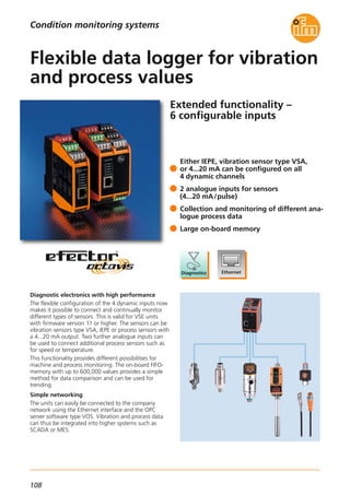
![109
(04.2015)
Technical data
Operating voltage [V]
24 DC ± 20 %
IEPE input 24 DC + 20 %
Protection IP 20, III
Ambient temperature [°C] 0...70
Housing VSE002
VSE100
DIN rail 1"
DIN rail 2"
Diagnostic electronics
VSE002, VSE100
Dimensions
50 114
LEDs
2
1
105
35,5
Wiring diagram
18
17
20
19
14
13
16
15
22
21
24
23
6
5
8
7
2
1
4
3
10
9
12
11
Supply L- (GND)
OU 1: switch/analog
OU 2: switch
IN 1 (0/4...20 mA / pulse)
GND 1
IN 2 (0/4...20 mA / pulse)
GND 2
1
2
3
4
BN
WH
BU
BK
4
3
2
1
BK
BU
WH
BN
I/O 7
30
29
32
31
34
33
36
35
26
25
28
27
43
44
41
42
47
48
45
46
39
40
37
38
GND
I/O 8
GND
I/O 5
GND
I/O 6
GND
I/O 1
GND
I/O 2
GND
I/O 3
GND
I/O 4
GND
U-OUT (0...10 V)
GND
U-IN 1 (0...10 V)
GND 1
U-IN 2 (0...10 V)
GND 2
1
2
3
4
BN
WH
BU
BK
1
2
3
4
BN
WH
BU
BK
Supply L+ (24 V DC ±20 %)
Data interface
Ethernet TCP/IP,
(10 / 100 MBits)
History function integrated
1) Ethernet interface
2) Combicon connector with screw connectors (optional)
Inputs / Outputs
VSE002
4 dynamic inputs,
sensor type VSA/IEPE/4...20mA
in any combination
2 analogue inputs
(0/4...20 mA or pulse 24 V)
1x digital alarm output
(PNP 100 mA)
1x selectable digital
(PNP 100 mA) or
analogue (0/4...20 mA / 0...10 V)
alarm output
Inputs / Outputs
VSE100
4 dynamic inputs,
sensor type VSA/IEPE/4...20mA
in any combination
2 analogue inputs (0/4...20 mA
or 0...10 V or pulse 24 V)
1x digital alarm output
(PNP 100 mA)
1 x selectable digital
(PNP 100 mA) or
analogue (0/4...20 mA / 0...10 V)
alarm output
8 x digital outputs / inputs
(freely configurable)
(PNP 100 mA)
Parameter software VES004
octavis OPC server software
German / English
VOS001
Connection cable
Ethernet cross-over patch cable
2 m, PVC cable,
RJ45 plug / RJ45 plug
EC2080
Connection cable
Ethernet cross-over patch cable
5 m, PVC cable,
RJ45 plug / RJ45 plug
E30112
Example VSE100
Vibration monitoring systems
Condition monitoring systems
For further technical data please go to: www.ifm.com
Accessories
Type Description Order
no.](https://image.slidesharecdn.com/ifm-innovations-topproducts-2015-2016-gb-160202102146/85/Innovations-2015-2016-110-320.jpg)
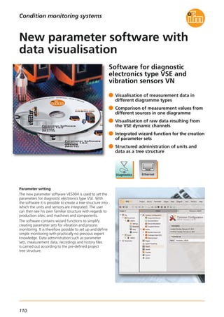
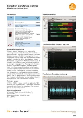

![113
(11.2015)
Mobile controllers
Functions and advantages
The compact, flexible and inexpensive mini controller
replaces the conventional relay logic and also demanding
and complex process controllers.
• Mechanical design
The control electronics integrated in a compact
plastic housing provides all the necessary connections
for the inputs and outputs, communication and pro-
gramming. The coded connectors for mobile use are
easy to handle and available all over the world. The
connection of sensors and actuators is carried out
without further external wiring. Due to an increase of
the protection rating through a cover and a pluggable
cable seal the BasicController can also be used in areas
that are exposed to splashing water.
• Powerful electronics
The integrated 32-bit processor and the electronics
are optimally tailored to the application. Inputs and
outputs can be configured to the application via the
user program. The powerful plug-in relay outputs
ensure the connection of high-current consumers.
All relay outputs are with diagnostic capability and
individually protected. Each output has a freely pro-
grammable status LED. Thanks to the additional
multi-functional inputs a flexible control module for
mobile machines is available.
• Programmable to IEC 61131-3
The CODESYS software enables a clear and easy
creation of the application software for the user.
The control module BasicController supports all
common CODESYS programming languages. Simple
and clearly structured function libraries are available
for communication and special device functions.
• Communication interfaces
The BasicController is equipped with two CAN inter-
faces to ISO 11898. These interfaces are used to
exchange data with the connected BasicDisplay,
further BasicController modules or the engine
controller. Among others, the interfaces support the
CANopen protocol and the J1939 protocol. The CAN
interfaces are also used for programming.
To do so, the unit electronics is directly and con-
veniently activated via the powerful PC-CAN interface
CANfox. In this way, operating system and application
program can be loaded or parameters changed.
Applications:
compact construction machines, attachments,
mini vehicles, special functions
Inputs (total):
Digital, analogue, frequency
Digital, resistance measurement
8
4
4
Outputs (total):
Micro relay ISO 7588-3,
15 A (total current max. 60 A)
Diagnostics via NO and NC contact of
the relay. Protected via mini controller
to DIN ISO 8820-3
6
Data memory SRAM [kB] 592
Data memory Flash [kB] 1536
Data memory (retain), FRAM [kB] 1
For further technical details please visit: www.ifm.com
Systems for mobile machines
Description Order
no.
BasicController relay 8 I / 6 O relay CR0431
Technical data
BasicController relay
The products
Housing
Plastic,
potted
Device connection
AMP blade male terminals
6.3 mm
Protection rating,
with cover EC0401, EC0402
IP 20
IP 54
Operating voltage [V DC] 8...32
Current consumption [mA] ≤ 45
Temperature range
Operation [°C]
Storage [°C]
-40...75
-40...85
Indicators LED Red / green
Processor PowerPC, 50 MHz
Supported CAN protocols
CANopen
(DS 301 V 4.1)
SAE J 1939
free CAN protocol
Standards and tests
(extract)
CE,
E1 (UN-ECE R10)
Starter set consisting of BasicController 12 I / 8 O,
BasicRelay, BasicDisplay incl. software, power supply,
cable and accessories
EC0400
Module cover IP 54
without display recess, with cable seal
EC0401
Plug set for BasicController relay EC0464
Mounting and contact set for
BasicController relay EC0465
Relay and fuse set for
12 V applications
EC0466
Relay and fuse set for
24 V applications
EC0467
CAN programming interface CANfox EC2112
Adapter set CAN/RS232 for CANfox EC2113
CODESYS programming software, German CP9006
CODESYS programming software, English CP9008
Programming software CODESYS V 2.3](https://image.slidesharecdn.com/ifm-innovations-topproducts-2015-2016-gb-160202102146/85/Innovations-2015-2016-114-320.jpg)

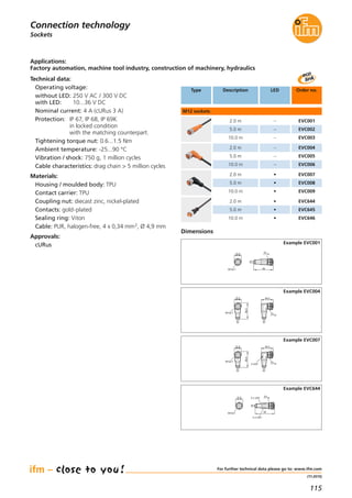
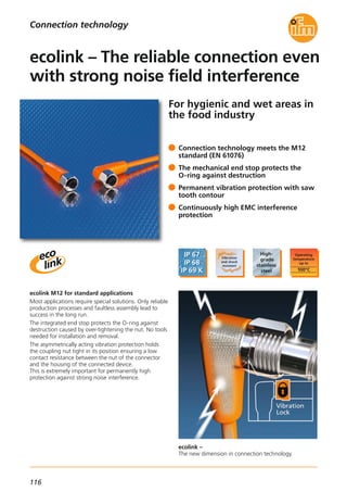
![117
(04.2015)
Sockets
For further technical details please visit: www.ifm.com
Connection technology
Technical data:
Operating voltage:
4-pole: 50 V AC / 60 V DC
5-pole: 30 V AC / 36 V DC
Nominal current: 4 A
Protection: IP 65, IP 67, IP 68, IP 69K / III
In locked condition with the matching counterpart.
Tightening torque nut: 0.6...1.5 Nm
Note the maximum value of the counterpart.
Ambient temperature:
-25...100 °C, cable firmly laid
5...100 °C, cable moved
Cable characteristics:
drag chain, 1 million cycles
Materials:
Housing / moulded body: PVC
Coupling nut: high-grade stainless steel
(316L / (1.4404)
Contacts: gold-plated
Sealing ring: EPDM
Cable: PVC, shielded,
4 x 0.34 mm2, Ø 5.2 mm
5 x 0.25 mm2, Ø 5.2 mm
Approvals:
cULus in preparation
Dimensions
15,5
M12x1 45
14
Example EVT381
15,5
M12x1
36,5
26,5
14
Example EVT385
Type Connection /
cable
Order
no.
Number of
poles
Screen not connected
Shielding characteristics
Screen connected
x: Frequency in [MHz]
y: Shielding characteristics in [dB]
2.0 m EVT381
5.0 m EVT382
10.0 m EVT383
4
4
4
25.0 m
2.0 m
5.0 m
10.0 m
25.0 m
2.0 m
5.0 m
10.0 m
25.0 m
2.0 m
5.0 m
10.0 m
25.0 m
EVT3844
EVT385
EVT386
EVT387
4
4
4
EVT3884
EVT389
EVT390
EVT391
5
5
5
EVT3925
EVT393
EVT394
EVT395
5
5
5
EVT3965
2.0 m EVT397
5.0 m EVT398
10.0 m EVT399
4
4
4
25.0 m
2.0 m
5.0 m
10.0 m
25.0 m
2.0 m
5.0 m
10.0 m
25.0 m
2.0 m
5.0 m
10.0 m
25.0 m
EVT4004
EVT401
EVT402
EVT403
4
4
4
EVT4044
EVT405
EVT406
EVT407
5
5
5
EVT4085
EVT409
EVT410
EVT411
5
5
5
EVT4125](https://image.slidesharecdn.com/ifm-innovations-topproducts-2015-2016-gb-160202102146/85/Innovations-2015-2016-118-320.jpg)

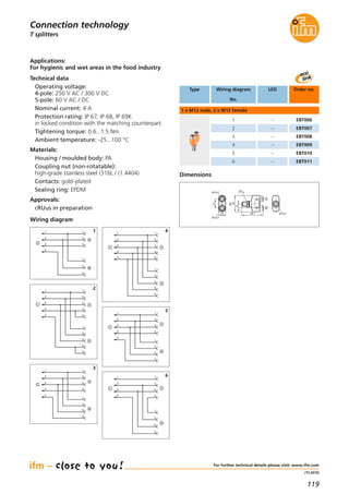

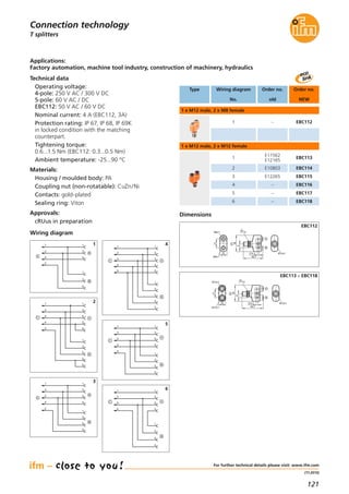
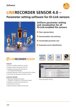
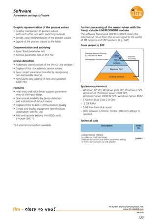
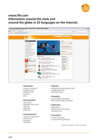


The document describes ifm's product catalog for 2015/2016, including innovations in various sensor technologies. It provides details on 3D smart sensors, industrial imaging sensors, photoelectric sensors, position sensors, magnetic sensors, laser sensors, encoders, flow sensors, level sensors, pressure sensors, temperature sensors, process sensors, identification systems, vibration monitoring systems, connection technology, and software. The catalog highlights new products, technologies, and features across ifm's range of sensors and systems.


