SlideShare a Scribd company logo
1 of 3
Download to read offline
International Journal of Engineering and Technical Research (IJETR)
ISSN: 2321-0869, Volume-1, Issue-10, December 2013
49 www.erpublication.org

Abstract— If water is put on different level then from upper
level to lower level it flows automatically for it’s same height
principle. If we submerge a bucket in a water tank and pull it up
holding it’s open faces vertically down then water enters into the
bucket and the level goes up as far as the bucket pulled up
because air give pressure on open water and water enters into
the bucket to fill up the void area. Because the void area has no
pressure. Now if we can attach a pipe from the upper part of the
bucket and keep it’s open end down than the bucket’s pulled up
height from the water then water will automatically come out
from the bucket. Now if we fix a generator output terminal shaft
with a fan fixed on it in the water flow then the shaft will rotate
and eventually the generator will output electricity. This is how
electricity is generated without fuel or any raw material or not
from flowing water rather from stagnant water.
Another method (Method 2) is on the same principle of water
(Same height principle) is discussed later.
Index Terms— This is how electricity is generated
without fuel.
I. INTRODUCTION
Here is a manuscript for generating electricity on stagnant
water without fuel or other raw material.
Process Design and materials needed :
Manuscript received December 09, 2013.
Shubhankar Paul, Passed BE in Electrical Engineering from Jadavpur
University in 2007. Worked at IBM as Manual Tester with designation
Application Consultant for 3 years 4 months.
the bucket will be hold by a holder. This is not shown in the
figure.
So, materials needed are stagnant water pool, generator, big
bucket. Pipe, pipe holder and bucket lifter.
II. PHYSICS BEHIND :
When the bucket is pulled up the water level decreases and the
volume of water that decreases is the volume that is inside the
bucket. So, if we make the bucket narrow and of more height
then water level will be up more and from pipe water will
emerge at more speed.
Say, the tank level is decreased by height h and the area of the
base of the tank is a. The area of the base of the bucket is A
and height of the bucket is H.
Then, ah = AH
 H = ah/A
 Less the area of the bucket and more the area of the
water tank the height (H) is more and hence the sped
of the water from pipe outlet is more. Hence
generator will find enough energy to start.
III. RISK :
When the pipe is fixed on the bucket it is to be cared that no
air is going into the bucket. Otherwise water level will fall
down due to the pressure of the air that has entered bucket
through pipe. So, we need to take a water filled pipe closed at
both end and after fixing it to the bucket the close end should
be made open so that air cannot enter anywhere.
IV. ADVANTAGE :
Advantages are as follows :
1) There is no cost of generating electricity.
2) No dam or big thing needs to be installed so that initial
cost is also low.
3) Once in action then maintenance cost is minimum as
such no maintenance cost.
4) No big risk of the employees working over there.
5) It is pollution free.
V. LOSSES :
Eddy current loss will be there in the generator. We will
discuss this. Mutual Inductance will be there in the generator.
We will discuss this as well.
VI. EDDY CURRENT :
Consider a solid plate of metal which enters a region having a
magnetic field. Consider a loop drawn on the plate, a par of
which is in the field. As the plate moves, the magnetic flux
Generate Electricity on stagnant water without fuel or
any other raw material (Pollution free)
Shubhankar Paul
Generate Electricity on stagnant water without fuel or any other raw material (Pollution free)
50 www.erpublication.org
through the area bounded by the loop changes and hence a
current is induced, There may be a number of such loops on
the plate and hence currents are induced on the surface along a
variety of paths. Such currents are called EDDY
CURRENTS. The basic idea is that we do not have a definite
conducting loop to guide the induced current. The system
itself looks for the loops on the surface along which eddy
currents are induced. Because of the eddy currents in the
metal plate, thermal energy is produced in it. This energy
comes at the cost of the kinetic energy of the plae and the plate
slows down. This is known as electromagnetic damping.
Mutual Inductance :
Suppose two closed circuits are placed close to each other and
a current i is passed in one. It produces a magnetic field and
this field has a flux Φ through the area bounded by the other
circuit. As the magnetic field at a point is proportional to the
current producing it, we can write,
Φ = Mi
where M is a constant depending on the geometrical shapes of
the two circuits and their placing. This constant is called
mutual inductance of the given pair of circuits. If the same
flux is calculated through the area bounded by the first circuit,
the same proportionality constant M appears. If there are
more than one turns in a circuit, one has to add the flux
through each turn before applying equation Φ = Mi.
If the current i in one circuit changes with time, the flux
through the area bounded by the second circuit. This
phenomenon is called mutual inductance. From the above
equation the induced emf is
E = -dΦ/dt
= -Mdi/dt
A. Generator Principle :
An electrical generator is a machine which converts
mechanical energy (or power) into electrical energy (or
power).
The energy conversion is based on the principle of
dynamically (or motionally) induced e.m.f. Whenever a
conductor cuts magnetic flux, dynamically induced e.m.f. is
produced in it according to Faraday’s laws of electromagnetic
induction. This e.m.f. causes a current to flow if the conductor
circuit is closed.
Hence, two basic part of an electrical generator are i) a
magnetic field ad ii) a conductor or conductors which can so
move as to cut the flux.
B. Faraday’s law :
Whenever the flux of magnetic field through the area bounded
by a closed conducting loop changes, an emf is produced in a
loop. The emf is given by E = -dΦ/dt where Φ = ∫B.dS is the
flux of the magnetic field through the area.
Direction of Induced Current (Lenz’s Law) : The direction of
the induced current is such that it opposes the change that has
induced it.
The Origin of Induced EMF : The flux ∫B.dS can be changed
by
(a) Keeping the magnetic field constant as time
passes and moving whole or part of the loop.
(b) Keeping the loop at rest and changing the
magnetic field.
(c) Combination of (a) and (b), that is, by moving the
loop(partly or wholely) as well as by changing the
field.
C. Motional Emf :
Below shows a rod of length PQ l moving in a magnetic field
B with a constant velocity v. The length of the rod is
perpendicular to the magnetic field and the velocity is
perpendicular to both the magnetic field and the rod. The free
electrons of the wire also move with the velocity v together
with the random velocity they have in the rod. The magnetic
force due to the
random velocity is zero on the average. Thus, the magnetic
field exerts an average force Fb = qv×B on each free electron
where q = 1.6*10^(-19) C is the charge on the electron. This
force is towards QP and hence the free electrons will move
towards P. Negative charge is accumulated at P and positive
charge appears at Q. An electrostatic field E is developed
within the wire from Q to P. This field exerts a force Fe = qE
on each free electron. The charge keeps on accumulating until
a situation comes when Fb = Fe.
Or, |qv×B| = |qE| or vB =E.
After this, there is no resultant force on the fee electrons of the
wire PQ. The potential difference between the ends Q and P
is V = El = vBl.
Thus, it is magnetic force on the moving free electrons that
maintains the potential difference V = vBl and hence
produces an emf E = vBl.
As this emf is produced due to motion of a conductor it is
called motional emf.
VII. METHOD 2 :
A tank, filled with water, with moveable floor is required. A
moveable partition inside the tank which can be moved as
required as shown below in Figure 1:
Figure 1 :
International Journal of Engineering and Technical Research (IJETR)
ISSN: 2321-0869, Volume-1, Issue-10, December 2013
51 www.erpublication.org
Now, the floor of the tank is moved in right side keeping the
partition fixed as shown below :
Figure 2 :
Now, the partition is lowered and water flows to the lower
level side due to it’s same height principle and the fan rotates
due to water flow and electricity is generated as shown in the
figure below :
Figure 3 :
Now, when water in the left part and right part of the partition
becomes of same height, then the floor of the tank moved left
and the partition is raised to get the initial position again as
shown in Figure 1 above. Then again the same procedure is
followed to generate electricity.
OR
It can be done by moving the partition only as shown in below
figures :
Figure 4 :
Figure 5 :
Figure 6 :
Force required to Pull the Partition :
Let, the length, breadth, height of the tank are l, b, H
respectively and upto height h water is filled at equilibrium
position. Now if the partition is moved x distance in left and
then height of water level h₁ will be,
h*(l/2)*(b/2) = h₁*{(l/2) – x}*(b/2)
 h₁ = {h*(l/2)}/{(l/2) – x}
Change in potential energy = mg(h₁ - h). Where m = mass of
water in the left portion (or right portion of the partition) and g
is Gravitational constant.
This is the work needs to be done to put the partition from
equilibrium position to the position as shown in figure 5 (i.e.
to pull it x distance)
Now, work done = Force*displacement
 mg(h₁ - h) = F*x
 F = mg(h₁ - h)/x
 F = mgh{(l/2) – 1}/[x{(l/2) – x}]
VIII. ADVANTAGES :
1. The generation can be done anywhere in stagnant
water.
2. This method can be used in car to generate electricity.
3. It is pollution free.
4. All we need a moveable tank, a partition, water, a
generator and instrument to move the floor and
partition of the tank.
REFERENCES
[1] Concepts of Physics 2 by H. C. Verma
[2] A textbook of Electrical Technology IN S.I. UNITS volume II AC & DC
Machines by B.L. Theraja, A.K. Theraja.
Shubhankar Paul, Passed BE in Electrical Engineering from Jadavpur
University in 2007. Worked at IBM as Manual Tester with designation
Application Consultant for 3 years 4 months. Worked at IIT Bombay for 3
months as JRF. Published 2 papers at International Journal of Engineering
and Technology Research Vol1 Issue 7. There title is 1. Title : Generate
Electricity While Cycling ; 2. Title : Generate Electricity Without fuel or any
raw material. Here is the link of my papers

More Related Content

What's hot

faradays law and its applications ppt
faradays law and its applications pptfaradays law and its applications ppt
faradays law and its applications ppt
Indira Kundu
 
Wave energy converter
Wave energy converterWave energy converter
Wave energy converter
Ngk34
 
Electromagnetic theory
Electromagnetic theoryElectromagnetic theory
Electromagnetic theory
Kumar
 
ELECTROSTATIC INDUCTION AND GAUSS LAW
ELECTROSTATIC INDUCTION AND GAUSS LAWELECTROSTATIC INDUCTION AND GAUSS LAW
ELECTROSTATIC INDUCTION AND GAUSS LAW
Deep Chaudhari
 

What's hot (19)

5.Hall Effect
5.Hall Effect5.Hall Effect
5.Hall Effect
 
Ocean wave!!
Ocean wave!!Ocean wave!!
Ocean wave!!
 
Lecture 26 emf. induced fields. displacement currents.
Lecture 26   emf. induced fields. displacement currents.Lecture 26   emf. induced fields. displacement currents.
Lecture 26 emf. induced fields. displacement currents.
 
MAGNETOSTATICS
MAGNETOSTATICSMAGNETOSTATICS
MAGNETOSTATICS
 
faradays law and its applications ppt
faradays law and its applications pptfaradays law and its applications ppt
faradays law and its applications ppt
 
Ap unit 1
Ap unit 1Ap unit 1
Ap unit 1
 
Wave energy converter
Wave energy converterWave energy converter
Wave energy converter
 
Magnetic boundary conditions 3rd 4
Magnetic boundary conditions 3rd 4Magnetic boundary conditions 3rd 4
Magnetic boundary conditions 3rd 4
 
NCES Wave Plant
NCES Wave PlantNCES Wave Plant
NCES Wave Plant
 
UNIT IV - WAVE EQUATIONS AND THEIR SOLUTION
UNIT IV - WAVE EQUATIONS AND THEIR SOLUTION UNIT IV - WAVE EQUATIONS AND THEIR SOLUTION
UNIT IV - WAVE EQUATIONS AND THEIR SOLUTION
 
Bh curve patro-26.12.18
Bh curve  patro-26.12.18Bh curve  patro-26.12.18
Bh curve patro-26.12.18
 
Emft
EmftEmft
Emft
 
Electrical ciircuit&mechine
Electrical ciircuit&mechineElectrical ciircuit&mechine
Electrical ciircuit&mechine
 
Electricity Alternating Current
Electricity Alternating CurrentElectricity Alternating Current
Electricity Alternating Current
 
(P206)sheet electromagnetic induction_e
(P206)sheet electromagnetic induction_e(P206)sheet electromagnetic induction_e
(P206)sheet electromagnetic induction_e
 
Electromagnetic theory
Electromagnetic theoryElectromagnetic theory
Electromagnetic theory
 
Lecture 21 applications of moving charge in magnetic field
Lecture 21   applications of moving charge in magnetic fieldLecture 21   applications of moving charge in magnetic field
Lecture 21 applications of moving charge in magnetic field
 
ELECTROSTATIC INDUCTION AND GAUSS LAW
ELECTROSTATIC INDUCTION AND GAUSS LAWELECTROSTATIC INDUCTION AND GAUSS LAW
ELECTROSTATIC INDUCTION AND GAUSS LAW
 
Electromagnetic Theory
Electromagnetic Theory Electromagnetic Theory
Electromagnetic Theory
 

Similar to Ijetr012025

PHYSICS II - Supplemental Guide
PHYSICS II - Supplemental GuidePHYSICS II - Supplemental Guide
PHYSICS II - Supplemental Guide
Pritam Karmokar
 
Electricity and Magnetism
Electricity and MagnetismElectricity and Magnetism
Electricity and Magnetism
maliraza215
 
MU PHYSICS.docx
MU PHYSICS.docxMU PHYSICS.docx
MU PHYSICS.docx
MONISH93591
 

Similar to Ijetr012025 (20)

Motional electromotive force
Motional electromotive forceMotional electromotive force
Motional electromotive force
 
Electromagnetic induction
Electromagnetic inductionElectromagnetic induction
Electromagnetic induction
 
VandE GRAFF generator
VandE GRAFF generatorVandE GRAFF generator
VandE GRAFF generator
 
PHYSICS II - Supplemental Guide
PHYSICS II - Supplemental GuidePHYSICS II - Supplemental Guide
PHYSICS II - Supplemental Guide
 
2 1
2 12 1
2 1
 
2 1
2 12 1
2 1
 
24 pius augustine em induction & ac
24 pius augustine em induction & ac24 pius augustine em induction & ac
24 pius augustine em induction & ac
 
Wave energy_MR YORN THORT-EEE-ITC-Cambodia
Wave energy_MR YORN THORT-EEE-ITC-CambodiaWave energy_MR YORN THORT-EEE-ITC-Cambodia
Wave energy_MR YORN THORT-EEE-ITC-Cambodia
 
Physics Investigatory Project - Transformer
Physics Investigatory Project - TransformerPhysics Investigatory Project - Transformer
Physics Investigatory Project - Transformer
 
Chapter 1bbj.pptx
Chapter 1bbj.pptxChapter 1bbj.pptx
Chapter 1bbj.pptx
 
Chap29_PHY2049.pdf
Chap29_PHY2049.pdfChap29_PHY2049.pdf
Chap29_PHY2049.pdf
 
DC machine.ppt
DC machine.pptDC machine.ppt
DC machine.ppt
 
Faraday’s Law.pdf
Faraday’s Law.pdfFaraday’s Law.pdf
Faraday’s Law.pdf
 
Physics project abhishek
Physics project abhishekPhysics project abhishek
Physics project abhishek
 
Electricity and Magnetism
Electricity and MagnetismElectricity and Magnetism
Electricity and Magnetism
 
MU PHYSICS.docx
MU PHYSICS.docxMU PHYSICS.docx
MU PHYSICS.docx
 
MU PHYSICS.docx
MU PHYSICS.docxMU PHYSICS.docx
MU PHYSICS.docx
 
Faradays law of EMI.pptx
Faradays law of EMI.pptxFaradays law of EMI.pptx
Faradays law of EMI.pptx
 
Gauss LAW
Gauss LAWGauss LAW
Gauss LAW
 
Faraday’s Law of Induction.pdf
Faraday’s Law of Induction.pdfFaraday’s Law of Induction.pdf
Faraday’s Law of Induction.pdf
 

More from ER Publication.org

More from ER Publication.org (20)

Ijetr011101
Ijetr011101Ijetr011101
Ijetr011101
 
Ijetr021232
Ijetr021232Ijetr021232
Ijetr021232
 
Ijetr021229
Ijetr021229Ijetr021229
Ijetr021229
 
Ijetr021228
Ijetr021228Ijetr021228
Ijetr021228
 
Ijetr021226
Ijetr021226Ijetr021226
Ijetr021226
 
Ijetr021224
Ijetr021224Ijetr021224
Ijetr021224
 
Ijetr021221
Ijetr021221Ijetr021221
Ijetr021221
 
Ijetr021220
Ijetr021220Ijetr021220
Ijetr021220
 
Ijetr021215
Ijetr021215Ijetr021215
Ijetr021215
 
Ijetr021211
Ijetr021211Ijetr021211
Ijetr021211
 
Ijetr021210
Ijetr021210Ijetr021210
Ijetr021210
 
Ijetr021207
Ijetr021207Ijetr021207
Ijetr021207
 
Ijetr021146
Ijetr021146Ijetr021146
Ijetr021146
 
Ijetr021145
Ijetr021145Ijetr021145
Ijetr021145
 
Ijetr021144
Ijetr021144Ijetr021144
Ijetr021144
 
Ijetr021143
Ijetr021143Ijetr021143
Ijetr021143
 
Ijetr021140
Ijetr021140Ijetr021140
Ijetr021140
 
Ijetr021139
Ijetr021139Ijetr021139
Ijetr021139
 
Ijetr021138
Ijetr021138Ijetr021138
Ijetr021138
 
Ijetr021135
Ijetr021135Ijetr021135
Ijetr021135
 

Recently uploaded

Salient Features of India constitution especially power and functions
Salient Features of India constitution especially power and functionsSalient Features of India constitution especially power and functions
Salient Features of India constitution especially power and functions
KarakKing
 

Recently uploaded (20)

Fostering Friendships - Enhancing Social Bonds in the Classroom
Fostering Friendships - Enhancing Social Bonds  in the ClassroomFostering Friendships - Enhancing Social Bonds  in the Classroom
Fostering Friendships - Enhancing Social Bonds in the Classroom
 
Salient Features of India constitution especially power and functions
Salient Features of India constitution especially power and functionsSalient Features of India constitution especially power and functions
Salient Features of India constitution especially power and functions
 
General Principles of Intellectual Property: Concepts of Intellectual Proper...
General Principles of Intellectual Property: Concepts of Intellectual  Proper...General Principles of Intellectual Property: Concepts of Intellectual  Proper...
General Principles of Intellectual Property: Concepts of Intellectual Proper...
 
OSCM Unit 2_Operations Processes & Systems
OSCM Unit 2_Operations Processes & SystemsOSCM Unit 2_Operations Processes & Systems
OSCM Unit 2_Operations Processes & Systems
 
ICT role in 21st century education and it's challenges.
ICT role in 21st century education and it's challenges.ICT role in 21st century education and it's challenges.
ICT role in 21st century education and it's challenges.
 
Towards a code of practice for AI in AT.pptx
Towards a code of practice for AI in AT.pptxTowards a code of practice for AI in AT.pptx
Towards a code of practice for AI in AT.pptx
 
Unit 3 Emotional Intelligence and Spiritual Intelligence.pdf
Unit 3 Emotional Intelligence and Spiritual Intelligence.pdfUnit 3 Emotional Intelligence and Spiritual Intelligence.pdf
Unit 3 Emotional Intelligence and Spiritual Intelligence.pdf
 
ICT Role in 21st Century Education & its Challenges.pptx
ICT Role in 21st Century Education & its Challenges.pptxICT Role in 21st Century Education & its Challenges.pptx
ICT Role in 21st Century Education & its Challenges.pptx
 
Single or Multiple melodic lines structure
Single or Multiple melodic lines structureSingle or Multiple melodic lines structure
Single or Multiple melodic lines structure
 
Accessible Digital Futures project (20/03/2024)
Accessible Digital Futures project (20/03/2024)Accessible Digital Futures project (20/03/2024)
Accessible Digital Futures project (20/03/2024)
 
NO1 Top Black Magic Specialist In Lahore Black magic In Pakistan Kala Ilam Ex...
NO1 Top Black Magic Specialist In Lahore Black magic In Pakistan Kala Ilam Ex...NO1 Top Black Magic Specialist In Lahore Black magic In Pakistan Kala Ilam Ex...
NO1 Top Black Magic Specialist In Lahore Black magic In Pakistan Kala Ilam Ex...
 
Philosophy of china and it's charactistics
Philosophy of china and it's charactisticsPhilosophy of china and it's charactistics
Philosophy of china and it's charactistics
 
Food safety_Challenges food safety laboratories_.pdf
Food safety_Challenges food safety laboratories_.pdfFood safety_Challenges food safety laboratories_.pdf
Food safety_Challenges food safety laboratories_.pdf
 
HMCS Max Bernays Pre-Deployment Brief (May 2024).pptx
HMCS Max Bernays Pre-Deployment Brief (May 2024).pptxHMCS Max Bernays Pre-Deployment Brief (May 2024).pptx
HMCS Max Bernays Pre-Deployment Brief (May 2024).pptx
 
Graduate Outcomes Presentation Slides - English
Graduate Outcomes Presentation Slides - EnglishGraduate Outcomes Presentation Slides - English
Graduate Outcomes Presentation Slides - English
 
How to Create and Manage Wizard in Odoo 17
How to Create and Manage Wizard in Odoo 17How to Create and Manage Wizard in Odoo 17
How to Create and Manage Wizard in Odoo 17
 
21st_Century_Skills_Framework_Final_Presentation_2.pptx
21st_Century_Skills_Framework_Final_Presentation_2.pptx21st_Century_Skills_Framework_Final_Presentation_2.pptx
21st_Century_Skills_Framework_Final_Presentation_2.pptx
 
Tatlong Kwento ni Lola basyang-1.pdf arts
Tatlong Kwento ni Lola basyang-1.pdf artsTatlong Kwento ni Lola basyang-1.pdf arts
Tatlong Kwento ni Lola basyang-1.pdf arts
 
SOC 101 Demonstration of Learning Presentation
SOC 101 Demonstration of Learning PresentationSOC 101 Demonstration of Learning Presentation
SOC 101 Demonstration of Learning Presentation
 
Sociology 101 Demonstration of Learning Exhibit
Sociology 101 Demonstration of Learning ExhibitSociology 101 Demonstration of Learning Exhibit
Sociology 101 Demonstration of Learning Exhibit
 

Ijetr012025

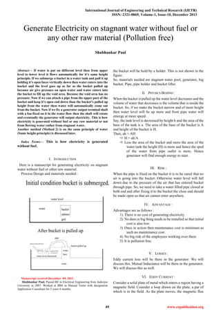
  • 1. International Journal of Engineering and Technical Research (IJETR) ISSN: 2321-0869, Volume-1, Issue-10, December 2013 49 www.erpublication.org  Abstract— If water is put on different level then from upper level to lower level it flows automatically for it’s same height principle. If we submerge a bucket in a water tank and pull it up holding it’s open faces vertically down then water enters into the bucket and the level goes up as far as the bucket pulled up because air give pressure on open water and water enters into the bucket to fill up the void area. Because the void area has no pressure. Now if we can attach a pipe from the upper part of the bucket and keep it’s open end down than the bucket’s pulled up height from the water then water will automatically come out from the bucket. Now if we fix a generator output terminal shaft with a fan fixed on it in the water flow then the shaft will rotate and eventually the generator will output electricity. This is how electricity is generated without fuel or any raw material or not from flowing water rather from stagnant water. Another method (Method 2) is on the same principle of water (Same height principle) is discussed later. Index Terms— This is how electricity is generated without fuel. I. INTRODUCTION Here is a manuscript for generating electricity on stagnant water without fuel or other raw material. Process Design and materials needed : Manuscript received December 09, 2013. Shubhankar Paul, Passed BE in Electrical Engineering from Jadavpur University in 2007. Worked at IBM as Manual Tester with designation Application Consultant for 3 years 4 months. the bucket will be hold by a holder. This is not shown in the figure. So, materials needed are stagnant water pool, generator, big bucket. Pipe, pipe holder and bucket lifter. II. PHYSICS BEHIND : When the bucket is pulled up the water level decreases and the volume of water that decreases is the volume that is inside the bucket. So, if we make the bucket narrow and of more height then water level will be up more and from pipe water will emerge at more speed. Say, the tank level is decreased by height h and the area of the base of the tank is a. The area of the base of the bucket is A and height of the bucket is H. Then, ah = AH  H = ah/A  Less the area of the bucket and more the area of the water tank the height (H) is more and hence the sped of the water from pipe outlet is more. Hence generator will find enough energy to start. III. RISK : When the pipe is fixed on the bucket it is to be cared that no air is going into the bucket. Otherwise water level will fall down due to the pressure of the air that has entered bucket through pipe. So, we need to take a water filled pipe closed at both end and after fixing it to the bucket the close end should be made open so that air cannot enter anywhere. IV. ADVANTAGE : Advantages are as follows : 1) There is no cost of generating electricity. 2) No dam or big thing needs to be installed so that initial cost is also low. 3) Once in action then maintenance cost is minimum as such no maintenance cost. 4) No big risk of the employees working over there. 5) It is pollution free. V. LOSSES : Eddy current loss will be there in the generator. We will discuss this. Mutual Inductance will be there in the generator. We will discuss this as well. VI. EDDY CURRENT : Consider a solid plate of metal which enters a region having a magnetic field. Consider a loop drawn on the plate, a par of which is in the field. As the plate moves, the magnetic flux Generate Electricity on stagnant water without fuel or any other raw material (Pollution free) Shubhankar Paul
  • 2. Generate Electricity on stagnant water without fuel or any other raw material (Pollution free) 50 www.erpublication.org through the area bounded by the loop changes and hence a current is induced, There may be a number of such loops on the plate and hence currents are induced on the surface along a variety of paths. Such currents are called EDDY CURRENTS. The basic idea is that we do not have a definite conducting loop to guide the induced current. The system itself looks for the loops on the surface along which eddy currents are induced. Because of the eddy currents in the metal plate, thermal energy is produced in it. This energy comes at the cost of the kinetic energy of the plae and the plate slows down. This is known as electromagnetic damping. Mutual Inductance : Suppose two closed circuits are placed close to each other and a current i is passed in one. It produces a magnetic field and this field has a flux Φ through the area bounded by the other circuit. As the magnetic field at a point is proportional to the current producing it, we can write, Φ = Mi where M is a constant depending on the geometrical shapes of the two circuits and their placing. This constant is called mutual inductance of the given pair of circuits. If the same flux is calculated through the area bounded by the first circuit, the same proportionality constant M appears. If there are more than one turns in a circuit, one has to add the flux through each turn before applying equation Φ = Mi. If the current i in one circuit changes with time, the flux through the area bounded by the second circuit. This phenomenon is called mutual inductance. From the above equation the induced emf is E = -dΦ/dt = -Mdi/dt A. Generator Principle : An electrical generator is a machine which converts mechanical energy (or power) into electrical energy (or power). The energy conversion is based on the principle of dynamically (or motionally) induced e.m.f. Whenever a conductor cuts magnetic flux, dynamically induced e.m.f. is produced in it according to Faraday’s laws of electromagnetic induction. This e.m.f. causes a current to flow if the conductor circuit is closed. Hence, two basic part of an electrical generator are i) a magnetic field ad ii) a conductor or conductors which can so move as to cut the flux. B. Faraday’s law : Whenever the flux of magnetic field through the area bounded by a closed conducting loop changes, an emf is produced in a loop. The emf is given by E = -dΦ/dt where Φ = ∫B.dS is the flux of the magnetic field through the area. Direction of Induced Current (Lenz’s Law) : The direction of the induced current is such that it opposes the change that has induced it. The Origin of Induced EMF : The flux ∫B.dS can be changed by (a) Keeping the magnetic field constant as time passes and moving whole or part of the loop. (b) Keeping the loop at rest and changing the magnetic field. (c) Combination of (a) and (b), that is, by moving the loop(partly or wholely) as well as by changing the field. C. Motional Emf : Below shows a rod of length PQ l moving in a magnetic field B with a constant velocity v. The length of the rod is perpendicular to the magnetic field and the velocity is perpendicular to both the magnetic field and the rod. The free electrons of the wire also move with the velocity v together with the random velocity they have in the rod. The magnetic force due to the random velocity is zero on the average. Thus, the magnetic field exerts an average force Fb = qv×B on each free electron where q = 1.6*10^(-19) C is the charge on the electron. This force is towards QP and hence the free electrons will move towards P. Negative charge is accumulated at P and positive charge appears at Q. An electrostatic field E is developed within the wire from Q to P. This field exerts a force Fe = qE on each free electron. The charge keeps on accumulating until a situation comes when Fb = Fe. Or, |qv×B| = |qE| or vB =E. After this, there is no resultant force on the fee electrons of the wire PQ. The potential difference between the ends Q and P is V = El = vBl. Thus, it is magnetic force on the moving free electrons that maintains the potential difference V = vBl and hence produces an emf E = vBl. As this emf is produced due to motion of a conductor it is called motional emf. VII. METHOD 2 : A tank, filled with water, with moveable floor is required. A moveable partition inside the tank which can be moved as required as shown below in Figure 1: Figure 1 :
  • 3. International Journal of Engineering and Technical Research (IJETR) ISSN: 2321-0869, Volume-1, Issue-10, December 2013 51 www.erpublication.org Now, the floor of the tank is moved in right side keeping the partition fixed as shown below : Figure 2 : Now, the partition is lowered and water flows to the lower level side due to it’s same height principle and the fan rotates due to water flow and electricity is generated as shown in the figure below : Figure 3 : Now, when water in the left part and right part of the partition becomes of same height, then the floor of the tank moved left and the partition is raised to get the initial position again as shown in Figure 1 above. Then again the same procedure is followed to generate electricity. OR It can be done by moving the partition only as shown in below figures : Figure 4 : Figure 5 : Figure 6 : Force required to Pull the Partition : Let, the length, breadth, height of the tank are l, b, H respectively and upto height h water is filled at equilibrium position. Now if the partition is moved x distance in left and then height of water level h₁ will be, h*(l/2)*(b/2) = h₁*{(l/2) – x}*(b/2)  h₁ = {h*(l/2)}/{(l/2) – x} Change in potential energy = mg(h₁ - h). Where m = mass of water in the left portion (or right portion of the partition) and g is Gravitational constant. This is the work needs to be done to put the partition from equilibrium position to the position as shown in figure 5 (i.e. to pull it x distance) Now, work done = Force*displacement  mg(h₁ - h) = F*x  F = mg(h₁ - h)/x  F = mgh{(l/2) – 1}/[x{(l/2) – x}] VIII. ADVANTAGES : 1. The generation can be done anywhere in stagnant water. 2. This method can be used in car to generate electricity. 3. It is pollution free. 4. All we need a moveable tank, a partition, water, a generator and instrument to move the floor and partition of the tank. REFERENCES [1] Concepts of Physics 2 by H. C. Verma [2] A textbook of Electrical Technology IN S.I. UNITS volume II AC & DC Machines by B.L. Theraja, A.K. Theraja. Shubhankar Paul, Passed BE in Electrical Engineering from Jadavpur University in 2007. Worked at IBM as Manual Tester with designation Application Consultant for 3 years 4 months. Worked at IIT Bombay for 3 months as JRF. Published 2 papers at International Journal of Engineering and Technology Research Vol1 Issue 7. There title is 1. Title : Generate Electricity While Cycling ; 2. Title : Generate Electricity Without fuel or any raw material. Here is the link of my papers